EP2088309A1 - High-pressure fuel feed pump - Google Patents
High-pressure fuel feed pump Download PDFInfo
- Publication number
- EP2088309A1 EP2088309A1 EP07792693A EP07792693A EP2088309A1 EP 2088309 A1 EP2088309 A1 EP 2088309A1 EP 07792693 A EP07792693 A EP 07792693A EP 07792693 A EP07792693 A EP 07792693A EP 2088309 A1 EP2088309 A1 EP 2088309A1
- Authority
- EP
- European Patent Office
- Prior art keywords
- fuel
- leak
- pressure
- portions
- pressure pump
- Prior art date
- Legal status (The legal status is an assumption and is not a legal conclusion. Google has not performed a legal analysis and makes no representation as to the accuracy of the status listed.)
- Withdrawn
Links
Images




Classifications
-
- F—MECHANICAL ENGINEERING; LIGHTING; HEATING; WEAPONS; BLASTING
- F02—COMBUSTION ENGINES; HOT-GAS OR COMBUSTION-PRODUCT ENGINE PLANTS
- F02M—SUPPLYING COMBUSTION ENGINES IN GENERAL WITH COMBUSTIBLE MIXTURES OR CONSTITUENTS THEREOF
- F02M59/00—Pumps specially adapted for fuel-injection and not provided for in groups F02M39/00 -F02M57/00, e.g. rotary cylinder-block type of pumps
- F02M59/02—Pumps specially adapted for fuel-injection and not provided for in groups F02M39/00 -F02M57/00, e.g. rotary cylinder-block type of pumps of reciprocating-piston or reciprocating-cylinder type
- F02M59/04—Pumps specially adapted for fuel-injection and not provided for in groups F02M39/00 -F02M57/00, e.g. rotary cylinder-block type of pumps of reciprocating-piston or reciprocating-cylinder type characterised by special arrangement of cylinders with respect to piston-driving shaft, e.g. arranged parallel to that shaft or swash-plate type pumps
-
- F—MECHANICAL ENGINEERING; LIGHTING; HEATING; WEAPONS; BLASTING
- F02—COMBUSTION ENGINES; HOT-GAS OR COMBUSTION-PRODUCT ENGINE PLANTS
- F02M—SUPPLYING COMBUSTION ENGINES IN GENERAL WITH COMBUSTIBLE MIXTURES OR CONSTITUENTS THEREOF
- F02M55/00—Fuel-injection apparatus characterised by their fuel conduits or their venting means; Arrangements of conduits between fuel tank and pump F02M37/00
-
- F—MECHANICAL ENGINEERING; LIGHTING; HEATING; WEAPONS; BLASTING
- F02—COMBUSTION ENGINES; HOT-GAS OR COMBUSTION-PRODUCT ENGINE PLANTS
- F02M—SUPPLYING COMBUSTION ENGINES IN GENERAL WITH COMBUSTIBLE MIXTURES OR CONSTITUENTS THEREOF
- F02M59/00—Pumps specially adapted for fuel-injection and not provided for in groups F02M39/00 -F02M57/00, e.g. rotary cylinder-block type of pumps
- F02M59/02—Pumps specially adapted for fuel-injection and not provided for in groups F02M39/00 -F02M57/00, e.g. rotary cylinder-block type of pumps of reciprocating-piston or reciprocating-cylinder type
- F02M59/10—Pumps specially adapted for fuel-injection and not provided for in groups F02M39/00 -F02M57/00, e.g. rotary cylinder-block type of pumps of reciprocating-piston or reciprocating-cylinder type characterised by the piston-drive
- F02M59/102—Mechanical drive, e.g. tappets or cams
-
- F—MECHANICAL ENGINEERING; LIGHTING; HEATING; WEAPONS; BLASTING
- F02—COMBUSTION ENGINES; HOT-GAS OR COMBUSTION-PRODUCT ENGINE PLANTS
- F02M—SUPPLYING COMBUSTION ENGINES IN GENERAL WITH COMBUSTIBLE MIXTURES OR CONSTITUENTS THEREOF
- F02M59/00—Pumps specially adapted for fuel-injection and not provided for in groups F02M39/00 -F02M57/00, e.g. rotary cylinder-block type of pumps
- F02M59/44—Details, components parts, or accessories not provided for in, or of interest apart from, the apparatus of groups F02M59/02 - F02M59/42; Pumps having transducers, e.g. to measure displacement of pump rack or piston
- F02M59/442—Details, components parts, or accessories not provided for in, or of interest apart from, the apparatus of groups F02M59/02 - F02M59/42; Pumps having transducers, e.g. to measure displacement of pump rack or piston means preventing fuel leakage around pump plunger, e.g. fluid barriers
Definitions
- the present invention relates to a high-pressure fuel supply pump.
- a high-pressure fuel supply pump that has conventionally come to be used for the purpose of supplying high-pressure fuel to a common rail system, for example, has a configuration where, as shown in FIG. 6 , a plunger 102 housed so as to be capable of reciprocal motion inside a barrel 101 reciprocally moves in accordance with the rotation of a cam shaft 103 to pressurize fuel supplied to the inside of the barrel 101 via an inlet/outlet valve 104 and where the thus obtained high-pressure fuel is sent to the outside by the inlet/outlet valve 104.
- JP-A-8-68370 there is disclosed a configuration of a high-pressure fuel supply pump that includes two return passages, with one of the two return passages being connected to a fuel tank.
- the conventional high-pressure fuel pump shown in FIG. 6 is configured such that leak fuel, which is some of the high-pressure fuel pressurized inside the barrel 101 used for fuel lubrication of the barrel 101, is supplied back to the barrel 101 through a passage 105, so particularly in an operating state where the discharge fuel amount becomes small, the temperatures of the barrel 101 and the plunger 102 rise because of the above-described circulation of that fuel, and this has been a large factor causing fuel injection efficiency to be lowered.
- the configuration disclosed in JP-A-8-68370 has the problem that, in the case of a configuration that includes plural high-pressure pump portions, the configuration of the return passages for handling the leak fuel becomes complicated and causes costs to rise.
- a high-pressure fuel supply pump that includes plural high-pressure pump portions configured to pressurize, with plungers, fuel that has been sucked into the insides of barrels and to discharge high-pressure fuel, and with fuel lubrication between the plungers and the barrels being performed by at least some of the high-pressure fuel in each of the plural high-pressure pump portions, wherein each of the high-pressure pump portions includes a leak fuel takeout portion for taking out leak fuel generated for the fuel lubrication from the insides of the barrels to the outside, and the leak fuel that has been taken out from each of the leak fuel takeout portions is guided to a fuel low-pressure side by a leak separate feed path.
- the leak fuel which is some of the fuel used for the fuel lubrication between the plungers and the barrels, is not circulated and supplied to the barrels, a rise in the temperature of the plungers is controlled, and fuel injection efficiency can be improved with a simple configuration.
- FIG. 1 is a diagram generally showing the exterior of an embodiment of a high-pressure fuel supply pump to which the present invention has been applied.
- a high-pressure fuel supply pump 1 is used as a supply pump of a common rail system (not shown) that is used as a fuel injection system for a diesel engine, and in a body 2, there are disposed four high-pressure pump portions comprising a first high-pressure pump portion 1A to a fourth high-pressure pump portion 1D that are driven with a predetermined phase difference by a cam shaft (see FIG. 2 ) that is driven by rotational driving force from the unillustrated diesel engine.
- FIG. 2 is a pump cross-sectional diagram for describing the first high-pressure pump portion 1A.
- the first high-pressure pump portion 1A will be described in detail with reference to FIG. 2 , but the configurations of the second high-pressure pump portion 1B to the fourth high-pressure pump portion 1D are also the same as the configuration of the first high-pressure pump portion 1A.
- a pump housing a common base end portion 3Y of the pump housing 3 is formed in a substantial circular cylinder shape that has an axial line in a direction perpendicular to the page surface, and a cam shaft 4 is disposed on the same axis inside the common base end portion 3Y. Additionally, a first circular cylinder portion 3A is formed integrally on the common base end portion 3Y of the pump housing 3, and a main structure portion of the first high-pressure pump portion 1A is incorporated inside the first circular cylinder portion 3A.
- second to fourth circular cylinder portions 3B, 3C and 3D are formed integrally on the common base end portion 3Y in the same manner as the first circular cylinder portion 3A for the second high-pressure pump portion 1B, the third high-pressure pump portion 1C and the fourth high-pressure pump portion 1D (see FIG. 1 ), and the first high-pressure pump portion 1A to the fourth high-pressure pump portion 1D are configured to be driven with a phase difference by the cam shaft 4.
- 11 is a barrel that is disposed coaxially inside the first circular cylinder portion 3A
- 12 is a plunger that is disposed so as to be capable of reciprocal motion along the axial line thereof inside a plunger chamber 11A of the barrel 11, and the plunger 12 is configured to be guided on an inner wall surface 3Aa of the barrel 11 and movable in the axial line direction of the first circular cylinder portion 3A.
- a base end portion 12A of the plunger 12 is pushed against a movement guidance member 13 by a resilient spring 14 via a spring seat 14a.
- a rotating roller 13B that is rotatably fitted together by a support rod 13A is disposed in the movement guidance member 13.
- the movement guidance member 13 is resiliently energized toward the cam shaft 4 by the resilient spring 14 interposed between the barrel 11 and the movement guidance member 13 such that the rotating roller 13B disposed as mentioned above in the movement guidance member 13 always pressure-contacts the cam shaft 4.
- Fuel inside an external fuel tank (not shown) is sucked into the plunger chamber 11A via fuel inlet paths 17, 15C and 15B when the plunger 12 moves back toward the cam shaft 4. This fuel that has been sucked in is pressurized when the plunger 12 rises, and high-pressure fuel is obtained.
- FIG. 15 What is represented by reference numeral 15 is an inlet/outlet valve assembly that is fixedly disposed on the distal end portion of the barrel 11 in order to take out the high-pressure fuel from the plunger chamber 11A.
- a leak fuel takeout portion 16 for taking out, to the outside, leak fuel generated as a result of the high-pressure fuel being supplied to the inside of the plunger chamber 11A in order to lubricate the area between the barrel 11 and the plunger 12 with fuel is disposed in the barrel 11.
- the leak fuel takeout portion 16 is configured by a fuel leak hole 16A, an annular port 16B that is disposed in an end portion on the plunger 12 side of the fuel leak hole 16A and is for accumulating the leak fuel inside the barrel, and an annual leak separate feed oil chamber 16C that is formed by an annular groove formed in an outer peripheral wall of the barrel 11 at the other end portion of the fuel leak hole 16A.
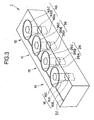
- FIG. 3 is a cross-sectional diagram along line A-A of FIG. 1 .
- the leak fuel takeout portion 26 is configured by a fuel leak hole 26A, an annular port 26B and a leak separate feed oil chamber 26C.
- the leak fuel takeout portion 36 is configured by a fuel leak hole 36A, an annular port 36B and a leak separate feed oil chamber 36C.
- the leak fuel takeout portion 46 is configured by a fuel leak hole 46A, an annular port 46B and a leak separate feed oil chamber 46C.
- the connecting transport path 50 is a leak separate feed path for collecting and guiding, toward a fuel low-pressure side, the leak fuel that has been taken out by each of the leak fuel takeout portions 16, 26, 36 and 46. Consequently, each of the quantities of the leak fuel that has been taken out by the leak fuel takeout portions 16, 26, 36 and 46 of the high-pressure pump portions is fed to the connecting transport path 50 from the corresponding leak separate feed oil chambers 16C, 26C, 36C and 46C and is separately fed to a fuel low-pressure side such as, for example, a fuel tank.
- a fuel low-pressure side such as, for example, a fuel tank.
- the high-pressure fuel pump 1 is configured as described above, so the leak fuel generated by the high-pressure fuel for the lubrication between the barrels and the plungers is fed to a fuel low-pressure portion such as a fuel tank via the leak fuel takeout portions 16, 26, 36 and 46 disposed in the high-pressure pump portions, respectively.
- a fuel low-pressure portion such as a fuel tank via the leak fuel takeout portions 16, 26, 36 and 46 disposed in the high-pressure pump portions, respectively.
- FIG. 3 there is shown a case where the leak fuel of each of the high-pressure pump portions is fed to a fuel tank via the connecting transport path 50 from the four leak separate feed oil chambers 16C, 26C, 36C and 46C.
- FIG. 4 is a diagram schematically showing this. However, the way that the leak fuel is allowed to escape is not limited to this configuration.
- FIG. 5 is a diagram showing another example of the way that the leak fuel is allowed to escape.
- the leak fuel is allowed to escape by disposing a dedicated escape passage 70 that interconnects the leak separate feed oil chambers 16C, 26C, 36C and 46C and connects the leak separate feed oil chambers 16C, 26C, 36C and 46C to another return passage inside a high-pressure pump.
- a dedicated escape passage 70 that interconnects the leak separate feed oil chambers 16C, 26C, 36C and 46C and connects the leak separate feed oil chambers 16C, 26C, 36C and 46C to another return passage inside a high-pressure pump.
- the leak fuel used for the fuel lubrication between the plungers and the barrels is not circulated and supplied to the barrels, so the high-pressure fuel supply pump according to the present invention controls a rise in the temperature of the plungers, can thus improve fuel injection efficiency, and is useful for the improvement of a high-pressure fuel supply pump.
Landscapes
- Engineering & Computer Science (AREA)
- Chemical & Material Sciences (AREA)
- Combustion & Propulsion (AREA)
- Mechanical Engineering (AREA)
- General Engineering & Computer Science (AREA)
- Fuel-Injection Apparatus (AREA)
- Details Of Reciprocating Pumps (AREA)
Abstract
A high-pressure fuel supply pump 1 where, in each of plural high-pressure pump portions (1A to 1D) configured to pressurize fuel that has been sucked into the insides of the barrels (11) and to output high-pressure fuel, fuel lubrication between plungers (12) and the barrels (11) is performed by at least some of the high-pressure fuel, wherein each of the high-pressure pump portions (1A to 1D) includes a leak fuel takeout portion (16, 26, 36, 46) for taking out leak fuel generated by the high-pressure fuel for the fuel lubrication from the insides of the barrels (11) to the outside, there is disposed a connecting oil path (50) for collecting and guiding, to a fuel low-pressure side, the leak fuel that has been taken out by the leak fuel takeout portions (16, 26, 36, 46), and the leak fuel is allowed to escape to a fuel tank via the connecting oil path (50).
Description
- The present invention relates to a high-pressure fuel supply pump.
- A high-pressure fuel supply pump that has conventionally come to be used for the purpose of supplying high-pressure fuel to a common rail system, for example, has a configuration where, as shown in
FIG. 6 , aplunger 102 housed so as to be capable of reciprocal motion inside abarrel 101 reciprocally moves in accordance with the rotation of acam shaft 103 to pressurize fuel supplied to the inside of thebarrel 101 via an inlet/outlet valve 104 and where the thus obtained high-pressure fuel is sent to the outside by the inlet/outlet valve 104. Further, inJP-A-8-68370 - The conventional high-pressure fuel pump shown in
FIG. 6 is configured such that leak fuel, which is some of the high-pressure fuel pressurized inside thebarrel 101 used for fuel lubrication of thebarrel 101, is supplied back to thebarrel 101 through apassage 105, so particularly in an operating state where the discharge fuel amount becomes small, the temperatures of thebarrel 101 and theplunger 102 rise because of the above-described circulation of that fuel, and this has been a large factor causing fuel injection efficiency to be lowered. Meanwhile, the configuration disclosed inJP-A-8-68370 - It is an object of the present invention to provide a high-pressure fuel supply pump that can solve the above-described problems in the prior art.
- In order to solve the above-described issues, according to the present invention, there is provided a high-pressure fuel supply pump that includes plural high-pressure pump portions configured to pressurize, with plungers, fuel that has been sucked into the insides of barrels and to discharge high-pressure fuel, and with fuel lubrication between the plungers and the barrels being performed by at least some of the high-pressure fuel in each of the plural high-pressure pump portions, wherein each of the high-pressure pump portions includes a leak fuel takeout portion for taking out leak fuel generated for the fuel lubrication from the insides of the barrels to the outside, and the leak fuel that has been taken out from each of the leak fuel takeout portions is guided to a fuel low-pressure side by a leak separate feed path.
- According to the present invention, the leak fuel, which is some of the fuel used for the fuel lubrication between the plungers and the barrels, is not circulated and supplied to the barrels, a rise in the temperature of the plungers is controlled, and fuel injection efficiency can be improved with a simple configuration.
-
-
FIG. 1 is a general external diagram of an embodiment of the present invention. -
FIG. 2 is a cross-sectional diagram of a first high-pressure pump portion shown inFIG. 1 . -
FIG. 3 is a diagram for describing leak fuel takeout portions shown cross-sectioned by line A-A shown inFIG. 1 . -
FIG. 4 is a diagram for describing a modification of the embodiment of the present invention. -
FIG. 5 is a diagram for describing a modification of the embodiment of the present invention. -
FIG. 6 is a diagram for describing a conventional high-pressure fuel supply pump. - In order to describe the present invention in greater detail, this will be described in accordance with the attached drawings.
-
FIG. 1 is a diagram generally showing the exterior of an embodiment of a high-pressure fuel supply pump to which the present invention has been applied. In the present embodiment, a high-pressurefuel supply pump 1 is used as a supply pump of a common rail system (not shown) that is used as a fuel injection system for a diesel engine, and in abody 2, there are disposed four high-pressure pump portions comprising a first high-pressure pump portion 1A to a fourth high-pressure pump portion 1D that are driven with a predetermined phase difference by a cam shaft (seeFIG. 2 ) that is driven by rotational driving force from the unillustrated diesel engine. -
FIG. 2 is a pump cross-sectional diagram for describing the first high-pressure pump portion 1A. Below, the first high-pressure pump portion 1A will be described in detail with reference toFIG. 2 , but the configurations of the second high-pressure pump portion 1B to the fourth high-pressure pump portion 1D are also the same as the configuration of the first high-pressure pump portion 1A. - What is represented by
reference numeral 3 is a pump housing, a commonbase end portion 3Y of thepump housing 3 is formed in a substantial circular cylinder shape that has an axial line in a direction perpendicular to the page surface, and acam shaft 4 is disposed on the same axis inside the commonbase end portion 3Y. Additionally, a firstcircular cylinder portion 3A is formed integrally on the commonbase end portion 3Y of thepump housing 3, and a main structure portion of the first high-pressure pump portion 1A is incorporated inside the firstcircular cylinder portion 3A. - Although they are not shown in
FIG. 2 , second to fourthcircular cylinder portions base end portion 3Y in the same manner as the firstcircular cylinder portion 3A for the second high-pressure pump portion 1B, the third high-pressure pump portion 1C and the fourth high-pressure pump portion 1D (seeFIG. 1 ), and the first high-pressure pump portion 1A to the fourth high-pressure pump portion 1D are configured to be driven with a phase difference by thecam shaft 4. - Next, the configuration of the first high-
pressure pump portion 1A will be described. 11 is a barrel that is disposed coaxially inside the firstcircular cylinder portion plunger chamber 11A of thebarrel 11, and theplunger 12 is configured to be guided on an inner wall surface 3Aa of thebarrel 11 and movable in the axial line direction of the firstcircular cylinder portion 3A. Abase end portion 12A of theplunger 12 is pushed against amovement guidance member 13 by aresilient spring 14 via aspring seat 14a. A rotatingroller 13B that is rotatably fitted together by asupport rod 13A is disposed in themovement guidance member 13. Themovement guidance member 13 is resiliently energized toward thecam shaft 4 by theresilient spring 14 interposed between thebarrel 11 and themovement guidance member 13 such that the rotatingroller 13B disposed as mentioned above in themovement guidance member 13 always pressure-contacts thecam shaft 4. - As a result, when the
cam shaft 4 is caused to rotate by the rotational force of the unillustrated diesel engine, themovement guidance member 13 reciprocally moves synchronously with the rotation of thecam shaft 4 such that theplunger 12 can be caused to reciprocally move inside thebarrel 11. - Fuel inside an external fuel tank (not shown) is sucked into the
plunger chamber 11A viafuel inlet paths plunger 12 moves back toward thecam shaft 4. This fuel that has been sucked in is pressurized when theplunger 12 rises, and high-pressure fuel is obtained. - What is represented by
reference numeral 15 is an inlet/outlet valve assembly that is fixedly disposed on the distal end portion of thebarrel 11 in order to take out the high-pressure fuel from theplunger chamber 11A. Inside acasing 15A of the inlet/outlet valve assembly 15, there are disposed thepassage 15B and thepassage 15C, and the high-pressure fuel that has been obtained by fuel pressurization inside theplunger chamber 11A is discharged to the outside from avalve body 15D through thepassage 15B. - A leak
fuel takeout portion 16 for taking out, to the outside, leak fuel generated as a result of the high-pressure fuel being supplied to the inside of theplunger chamber 11A in order to lubricate the area between thebarrel 11 and theplunger 12 with fuel is disposed in thebarrel 11. In the present embodiment, the leakfuel takeout portion 16 is configured by afuel leak hole 16A, anannular port 16B that is disposed in an end portion on theplunger 12 side of thefuel leak hole 16A and is for accumulating the leak fuel inside the barrel, and an annual leak separatefeed oil chamber 16C that is formed by an annular groove formed in an outer peripheral wall of thebarrel 11 at the other end portion of thefuel leak hole 16A. -
FIG. 3 is a cross-sectional diagram along line A-A ofFIG. 1 . As shown inFIG. 3 , in the second high-pressure pump portion 1B to the fourth high-pressure pump portion 1D, there are disposed leakfuel takeout portions fuel takeout portion 16. That is, the leakfuel takeout portion 26 is configured by afuel leak hole 26A, anannular port 26B and a leak separatefeed oil chamber 26C. The leakfuel takeout portion 36 is configured by afuel leak hole 36A, anannular port 36B and a leak separatefeed oil chamber 36C. The leakfuel takeout portion 46 is configured by afuel leak hole 46A, anannular port 46B and a leak separatefeed oil chamber 46C. - Additionally, the leak separate
feed oil chambers transport path 50. The connectingtransport path 50 is a leak separate feed path for collecting and guiding, toward a fuel low-pressure side, the leak fuel that has been taken out by each of the leakfuel takeout portions fuel takeout portions transport path 50 from the corresponding leak separatefeed oil chambers - The high-
pressure fuel pump 1 is configured as described above, so the leak fuel generated by the high-pressure fuel for the lubrication between the barrels and the plungers is fed to a fuel low-pressure portion such as a fuel tank via the leakfuel takeout portions plungers 11 does not rise because of the leak of the high-pressure fuel, and fuel injection efficiency can be remarkably improved in comparison to convention. - In
FIG. 3 , there is shown a case where the leak fuel of each of the high-pressure pump portions is fed to a fuel tank via the connectingtransport path 50 from the four leak separatefeed oil chambers FIG. 4 is a diagram schematically showing this. However, the way that the leak fuel is allowed to escape is not limited to this configuration. -
FIG. 5 is a diagram showing another example of the way that the leak fuel is allowed to escape. According to the configuration shown inFIG. 5 , the leak fuel is allowed to escape by disposing adedicated escape passage 70 that interconnects the leak separatefeed oil chambers feed oil chambers FIG. 5 , there is obtained the advantage that a new pipe is not required outside the high-pressure pump. It will be noted that, although inFIG. 4 there is shown a case where the connectingtransport path 50 passes through the centers of the leak separatefeed oil chambers transport path 50 to pass through the centers of the leak separatefeed oil chambers - As described above, the leak fuel used for the fuel lubrication between the plungers and the barrels is not circulated and supplied to the barrels, so the high-pressure fuel supply pump according to the present invention controls a rise in the temperature of the plungers, can thus improve fuel injection efficiency, and is useful for the improvement of a high-pressure fuel supply pump.
Claims (4)
- A high-pressure fuel supply pump that includes plural high-pressure pump portions configured to pressurize, with plungers, fuel that has been sucked into the insides of barrels and to discharge high-pressure fuel, and with fuel lubrication between the plungers and the barrels being performed by at least some of the high-pressure fuel in each of the plural high-pressure pump portions,
wherein each of the high-pressure pump portions includes a leak fuel takeout portion for taking out leak fuel generated for the fuel lubrication from the insides of the barrels to the outside, and
the leak fuel that has been taken out by each of the leak fuel takeout portions is guided to a fuel low-pressure side by a leak separate feed path. - The high-pressure fuel supply pump according to claim 1, wherein each of the leak fuel takeout portions comprises a fuel leak hole, an annular port that is disposed in an end portion on the plunger side of the fuel leak hole and is for collecting the leak fuel inside the barrel, and an annular leak separate feed oil chamber that is formed by an annular groove formed in an outer peripheral wall of the barrel at the other end portion of the fuel leak hole.
- The high-pressure fuel supply pump according to claim 2, wherein the leak separate feed path is a connecting oil feed path that interconnects each of the leak separate feed oil chambers of the plural high-pressure pump portions.
- The high-pressure fuel supply pump according to claim 2, wherein the leak separate feed path is a dedicated escape passage connected to another return passage inside a high-pressure pump, and the escape passage is connected to each of the leak separate feed oil chambers of the plural high-pressure pump portions.
Applications Claiming Priority (2)
| Application Number | Priority Date | Filing Date | Title |
|---|---|---|---|
| JP2006316693A JP2008128164A (en) | 2006-11-24 | 2006-11-24 | High pressure fuel supply pump |
| PCT/JP2007/066078 WO2008062589A1 (en) | 2006-11-24 | 2007-08-14 | High-pressure fuel feed pump |
Publications (2)
| Publication Number | Publication Date |
|---|---|
| EP2088309A1 true EP2088309A1 (en) | 2009-08-12 |
| EP2088309A4 EP2088309A4 (en) | 2010-06-02 |
Family
ID=39429530
Family Applications (1)
| Application Number | Title | Priority Date | Filing Date |
|---|---|---|---|
| EP07792693A Withdrawn EP2088309A4 (en) | 2006-11-24 | 2007-08-14 | High-pressure fuel feed pump |
Country Status (4)
| Country | Link |
|---|---|
| EP (1) | EP2088309A4 (en) |
| JP (1) | JP2008128164A (en) |
| CN (1) | CN101542107A (en) |
| WO (1) | WO2008062589A1 (en) |
Cited By (2)
| Publication number | Priority date | Publication date | Assignee | Title |
|---|---|---|---|---|
| EP2530315A1 (en) * | 2011-06-02 | 2012-12-05 | Delphi Technologies Holding S.à.r.l. | Fuel pump lubrication |
| EP2530316A1 (en) * | 2011-06-02 | 2012-12-05 | Delphi Technologies Holding S.à.r.l. | Fuel pump lubrication |
Families Citing this family (3)
| Publication number | Priority date | Publication date | Assignee | Title |
|---|---|---|---|---|
| CN201851248U (en) * | 2010-11-18 | 2011-06-01 | 博世汽车柴油系统股份有限公司 | High-pressure fuel pump |
| CN102465801B (en) * | 2010-11-18 | 2014-08-13 | 博世汽车柴油系统有限公司 | High-pressure fuel pump |
| CN201851241U (en) * | 2010-11-18 | 2011-06-01 | 博世汽车柴油系统股份有限公司 | High-pressure fuel oil pump |
Family Cites Families (7)
| Publication number | Priority date | Publication date | Assignee | Title |
|---|---|---|---|---|
| JPS586960A (en) * | 1981-07-03 | 1983-01-14 | Daido Steel Co Ltd | High manganese steel rail |
| JPS586960U (en) * | 1981-07-04 | 1983-01-17 | ヤンマーディーゼル株式会社 | fuel injection pump |
| DE3313322A1 (en) * | 1983-04-13 | 1984-10-18 | Klöckner-Humboldt-Deutz AG, 5000 Köln | INJECTION PUMP FOR A PISTON PISTON COMBUSTION ENGINE |
| US5339724A (en) * | 1991-03-05 | 1994-08-23 | Wartsila Diesel International Ltd. Oy | Arrangement for the lubrication of the piston member of a fuel injection pump |
| JP3522782B2 (en) * | 1993-02-12 | 2004-04-26 | ロバート ボッシュ ゲーエムベーハー | Pump device |
| JP3199105B2 (en) | 1994-06-24 | 2001-08-13 | 株式会社デンソー | High pressure fuel supply pump |
| JP3885506B2 (en) * | 2001-03-22 | 2007-02-21 | いすゞ自動車株式会社 | Fuel injection pump for dimethyl ether engine |
-
2006
- 2006-11-24 JP JP2006316693A patent/JP2008128164A/en active Pending
-
2007
- 2007-08-14 EP EP07792693A patent/EP2088309A4/en not_active Withdrawn
- 2007-08-14 WO PCT/JP2007/066078 patent/WO2008062589A1/en not_active Ceased
- 2007-08-14 CN CNA2007800432037A patent/CN101542107A/en active Pending
Cited By (5)
| Publication number | Priority date | Publication date | Assignee | Title |
|---|---|---|---|---|
| EP2530315A1 (en) * | 2011-06-02 | 2012-12-05 | Delphi Technologies Holding S.à.r.l. | Fuel pump lubrication |
| EP2530316A1 (en) * | 2011-06-02 | 2012-12-05 | Delphi Technologies Holding S.à.r.l. | Fuel pump lubrication |
| WO2012163686A2 (en) | 2011-06-02 | 2012-12-06 | Delphi Technologies Holding S.A.R.L. | Improvements to fuel pumps |
| WO2012163686A3 (en) * | 2011-06-02 | 2013-12-05 | Delphi Technologies Holding S.A.R.L. | Improvements to fuel pumps |
| US9291132B2 (en) | 2011-06-02 | 2016-03-22 | Delphi International Operations Luxembourg S.A.R.L. | Fuel pump assembly |
Also Published As
| Publication number | Publication date |
|---|---|
| CN101542107A (en) | 2009-09-23 |
| WO2008062589A1 (en) | 2008-05-29 |
| JP2008128164A (en) | 2008-06-05 |
| EP2088309A4 (en) | 2010-06-02 |
Similar Documents
| Publication | Publication Date | Title |
|---|---|---|
| JP4453028B2 (en) | High pressure fuel pump | |
| JP5529346B2 (en) | Pumps, especially fuel high-pressure pumps | |
| US9188096B2 (en) | Fuel pump and fuel supply system of internal combustion engine | |
| US9512836B2 (en) | Fuel pump for an internal combustion engine | |
| CN102472220B (en) | Pump unit | |
| EP2088309A1 (en) | High-pressure fuel feed pump | |
| JP2007315302A (en) | High pressure fuel pump | |
| CN105745445B (en) | Membrane pump | |
| US20190316558A1 (en) | High-Pressure Fuel Supply Pump | |
| JP2007224833A (en) | Fuel injection system for internal combustion engine | |
| WO2005068823A1 (en) | Fuel supply pump | |
| CN102465801B (en) | High-pressure fuel pump | |
| EP2711546B1 (en) | Tappet arrangement and pump | |
| WO2016117297A1 (en) | High-pressure pump and method for manufacturing same | |
| CN103534473B (en) | System for trandfer fluid | |
| KR102216489B1 (en) | Fuel pump for fueling an internal combustion piston engine | |
| KR20180121982A (en) | High pressure pump with fluid damper | |
| JP6610248B2 (en) | Supply pump mounting structure for cylinder block | |
| EP3173613B1 (en) | Fuel pump | |
| KR102239680B1 (en) | High pressure fuel pump assembly for internal combustion piston engines | |
| WO2020071087A1 (en) | Water injection pump | |
| EP3601778B1 (en) | A fuel pump for supplying fuel to an internal combustion piston engine | |
| CN104487699A (en) | High-pressure pump | |
| US11719207B2 (en) | Pump plunger assembly for improved pump efficiency | |
| CN101371032A (en) | Fuel injection systems for internal combustion engines |
Legal Events
| Date | Code | Title | Description |
|---|---|---|---|
| PUAI | Public reference made under article 153(3) epc to a published international application that has entered the european phase |
Free format text: ORIGINAL CODE: 0009012 |
|
| 17P | Request for examination filed |
Effective date: 20090624 |
|
| AK | Designated contracting states |
Kind code of ref document: A1 Designated state(s): DE FR GB |
|
| DAX | Request for extension of the european patent (deleted) | ||
| A4 | Supplementary search report drawn up and despatched |
Effective date: 20100507 |
|
| STAA | Information on the status of an ep patent application or granted ep patent |
Free format text: STATUS: THE APPLICATION IS DEEMED TO BE WITHDRAWN |
|
| 18D | Application deemed to be withdrawn |
Effective date: 20110411 |