EP2530316A1 - Fuel pump lubrication - Google Patents
Fuel pump lubrication Download PDFInfo
- Publication number
- EP2530316A1 EP2530316A1 EP11168572A EP11168572A EP2530316A1 EP 2530316 A1 EP2530316 A1 EP 2530316A1 EP 11168572 A EP11168572 A EP 11168572A EP 11168572 A EP11168572 A EP 11168572A EP 2530316 A1 EP2530316 A1 EP 2530316A1
- Authority
- EP
- European Patent Office
- Prior art keywords
- plunger
- fuel
- interface
- interface member
- rider
- Prior art date
- Legal status (The legal status is an assumption and is not a legal conclusion. Google has not performed a legal analysis and makes no representation as to the accuracy of the status listed.)
- Withdrawn
Links
Images


Classifications
-
- F—MECHANICAL ENGINEERING; LIGHTING; HEATING; WEAPONS; BLASTING
- F04—POSITIVE - DISPLACEMENT MACHINES FOR LIQUIDS; PUMPS FOR LIQUIDS OR ELASTIC FLUIDS
- F04B—POSITIVE-DISPLACEMENT MACHINES FOR LIQUIDS; PUMPS
- F04B1/00—Multi-cylinder machines or pumps characterised by number or arrangement of cylinders
- F04B1/04—Multi-cylinder machines or pumps characterised by number or arrangement of cylinders having cylinders in star- or fan-arrangement
-
- F—MECHANICAL ENGINEERING; LIGHTING; HEATING; WEAPONS; BLASTING
- F02—COMBUSTION ENGINES; HOT-GAS OR COMBUSTION-PRODUCT ENGINE PLANTS
- F02M—SUPPLYING COMBUSTION ENGINES IN GENERAL WITH COMBUSTIBLE MIXTURES OR CONSTITUENTS THEREOF
- F02M59/00—Pumps specially adapted for fuel-injection and not provided for in groups F02M39/00 -F02M57/00, e.g. rotary cylinder-block type of pumps
- F02M59/02—Pumps specially adapted for fuel-injection and not provided for in groups F02M39/00 -F02M57/00, e.g. rotary cylinder-block type of pumps of reciprocating-piston or reciprocating-cylinder type
- F02M59/10—Pumps specially adapted for fuel-injection and not provided for in groups F02M39/00 -F02M57/00, e.g. rotary cylinder-block type of pumps of reciprocating-piston or reciprocating-cylinder type characterised by the piston-drive
- F02M59/102—Mechanical drive, e.g. tappets or cams
-
- F—MECHANICAL ENGINEERING; LIGHTING; HEATING; WEAPONS; BLASTING
- F02—COMBUSTION ENGINES; HOT-GAS OR COMBUSTION-PRODUCT ENGINE PLANTS
- F02M—SUPPLYING COMBUSTION ENGINES IN GENERAL WITH COMBUSTIBLE MIXTURES OR CONSTITUENTS THEREOF
- F02M59/00—Pumps specially adapted for fuel-injection and not provided for in groups F02M39/00 -F02M57/00, e.g. rotary cylinder-block type of pumps
- F02M59/44—Details, components parts, or accessories not provided for in, or of interest apart from, the apparatus of groups F02M59/02 - F02M59/42; Pumps having transducers, e.g. to measure displacement of pump rack or piston
-
- F—MECHANICAL ENGINEERING; LIGHTING; HEATING; WEAPONS; BLASTING
- F04—POSITIVE - DISPLACEMENT MACHINES FOR LIQUIDS; PUMPS FOR LIQUIDS OR ELASTIC FLUIDS
- F04B—POSITIVE-DISPLACEMENT MACHINES FOR LIQUIDS; PUMPS
- F04B1/00—Multi-cylinder machines or pumps characterised by number or arrangement of cylinders
- F04B1/04—Multi-cylinder machines or pumps characterised by number or arrangement of cylinders having cylinders in star- or fan-arrangement
- F04B1/0404—Details or component parts
- F04B1/0426—Arrangements for pressing the pistons against the actuated cam; Arrangements for connecting the pistons to the actuated cam
Definitions
- This invention relates to pump assemblies suitable for use in common rail fuel injection systems of internal combustion engines.
- the invention relates to an improved pumping plunger for a high-pressure fuel pump, and an improved fuel pump of the type having at least one pumping plunger that is driven by an engine-driven cam or other appropriate drive arrangement.
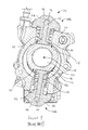
- FIG. 1 of the accompanying drawings is a sectional view of one known radial fuel pump, which will now be described to illustrate the prior art.
- the pump 100 of Figure 1 comprises two pumping plungers 102 that are approximately opposed across the rotational axis C of an engine-driven cam 104.
- Each plunger 102 is mounted within a plunger bore 106 provided in a respective pump head 108a, 108b.
- Each pump head 108a, 108b is mounted to a main pump housing 110.
- the main pump housing 110 also known as a cam box, defines an internal housing volume 112 within which the cam 104 is received.
- each plunger 102 causes pressurisation of fuel within a pump chamber 114 defined at one end of the associated plunger bore 106.
- the delivery of fuel from the pump chambers 114 to a high pressure supply line is controlled by means of delivery valves (not shown).
- the high pressure line supplies fuel to a common rail (not shown), or other accumulator volume, for delivery to downstream injectors of a common rail fuel system.
- the cam 104 carries a cam ring, or cam rider 116, which is provided with a pair of flats 118, one for each plunger 102.
- Each plunger 102 includes an integral interface member in the form of a foot 120.
- the foot 120 cooperates with the respective flat 118 on the cam rider 116 so that, as the foot 120 is driven upon rotation of the cam 104, drive is imparted to the plunger 102.
- each plunger 102 moves radially inward, under the influence of a return spring 122 in the form of a compression spring disposed between the plunger foot 120 and a pump head housing 124 of the respective pump head 108a, 108b.
- This part of the pumping cycle is referred to as the filling or return stroke of the plunger 102, during which fuel is drawn into the associated pump chamber 114 from a relatively low-pressure fuel supply (not shown).
- each plunger foot 120 tends to meet the respective rider flat 118 at a small inclined angle, instead of in a parallel configuration.
- the edge contact results in a local temperature increase, which undesirably heats other components within the fuel pump assembly.
- each plunger foot 120 in the known common rail fuel pump 100 of Figure 1 is formed as an arcuate contact surface.
- the arcuate contact surface reduces friction wear between the foot 120 and the rider 116 member by enabling improved freedom of movement between the foot 120 and the rider 116, particularly during translational movement of the rider 116 with respect to the foot 120 in use. This helps to avoid wear at the edges of the plunger feet 120.
- the arcuate contact surface gives rise to a hydrodynamic lubrication condition at the interface, since the arcuate surface assists in spreading lubricant contained in the housing volume 112 to create a lubricant film between the plunger foot 120 and the rider 116.
- the present invention resides in a high-pressure fuel pump assembly for use in an internal combustion engine, the fuel pump assembly comprising a pumping plunger for pressurising fuel within a pump chamber during a plunger pumping stroke, a rider member co-operable with a drive, and an interface member for imparting drive from the rider member to the pumping plunger to perform the plunger pumping stroke.
- the interface member has an interface side that is co-operable with the rider member.
- the pump assembly further comprises fluid flow means for providing a fluid flow path from the pump chamber to the interface side of the interface member such that, in use, a hydrostatic lubricating fuel film is generated between the interface member and the rider member on pressurisation of fuel in the pump chamber.
- the lubricating fuel film also serves to cool the interface member and the rider member.
- the hydrostatic lubricating fuel film is generated on pressurisation of fuel in the pump chamber, the lubrication is maximised during the part of the pumping cycle of the fuel pump assembly in which the load between the interface member and the rider member is at is highest.
- Providing fluid flow means in accordance with the present invention results in the loss of pressurised fuel from the pump chamber and an increase in dead volume.
- the inventors of the present invention have discovered that the benefits of reducing wear and improving cooling that arise as a result of the invention provide a desirable overall improvement in pump performance.
- the fluid flow means comprises a hydrostatic pocket in the interface side of the interface member.
- the hydrostatic pocket may, for example, comprise a recess in the interface side of the interface member.
- the fluid flow means may comprise a restrictor for creating a pressure drop in the fluid flow path between the pump chamber and the hydrostatic pocket.
- the fuel pressure in the hydrostatic pocket can be controlled such that a hydrostatic lubricating film is formed when the fuel in the pump chamber is pressurised above a threshold pressure.
- the threshold pressure may depend on the relative speed of movement of the rider member with respect to the interface member.
- the restrictor may comprise an orifice with a restricted cross-sectional area compared to the remainder of the fluid flow means.
- the interface member may comprise a hydrodynamic contact surface adjacent to the hydrostatic pocket such that, in use, a hydrodynamic lubricating fuel film is generated between the interface member and the rider member on relative translational movement of the interface member relative to the rider member.
- a lubricating fluid film can be generated between the interface member and the rider member even when the fuel in the pump chamber is not pressurised, for example on start-up of the pump or during a filling or return stroke of the pumping plunger.
- the hydrodynamic lubricating fluid film maintains lubrication when the hydrostatic fluid film is not present, so long as there is relative translational movement between the interface member and the rider.
- the contact surface may comprise a non-planar region.
- the contact surface or a part thereof may be arcuate, frustoconical, part spherical, part toroidal or a similar shape so that the contact surface defines a generally convex or bellied shape.
- the contact surface comprises an inner planar region and an outer frustoconical region.
- the hydrostatic pocket may be circular in plan, in which case and the contact surface may be annular and surrounds the pocket.
- the interface member is integral with the pumping plunger.
- the interface member is engageable with the pumping plunger.
- the interface member may be engaged or engageable with a stem of the pumping plunger.
- interface member and the pumping plunger can be made from two different materials, each being optimised for the conditions under which the respective components operate.
- the interface member may be configured to articulate with respect to the stem. In such a case, small rotational movements of the rider member with respect to the contact surface can be accommodated by articulation of the interface member with respect to the stem.
- the interface member may comprise socket means for receiving an end of the stem remote from the pump chamber.
- the end of the stem remote from the pump chamber may comprise socket means for receiving a projection or head portion of the interface member.
- the plunger may comprise a first connecting chamber provided in the stem and a second connecting chamber provided in the interface member.
- the first and second connecting chambers are co-operable to maintain fluid connection between the pump chamber and the hydrostatic pocket during articulation of the interface member with respect to the stem and serve to deliver lubricant to the joint between the stem and the interface member.
- the interface member preferably comprises a foot of the pumping plunger. In another embodiment, the interface member comprises a tappet.
- the invention resides in a pumping plunger for pressurising fuel within a pump chamber of a high-pressure fuel pump.
- the pumping plunger comprises a pumping end and an interface member remote from the pumping end.
- the interface member comprises an interface side having a hydrostatic pocket, and the pumping plunger comprises passage means for providing a fluid flow path between the pumping end and the hydrostatic pocket and a restrictor for restricting fuel flow into the hydrostatic pocket.
- the interface member comprises a hydrodynamic, arcuate contact surface adjacent to the hydrostatic pocket.
- a high pressure fuel pump 200 suitable for use in the fuel injection system of a compression ignition internal combustion engine.
- the fuel pump 200 is suitable for use in delivering high pressure fuel to a common rail of a common rail fuel injection system (not shown).
- the fuel pump 200 in Figure 2 comprises improved pumping plungers 201, which help to reduce frictional wear within the pump and consequently allow the pump 200 to operate at an output pressure in excess of that possible with known pump designs.
- the pump 200 includes a main pump housing 202 through which an engine-driven drive shaft (not shown) extends.
- the drive shaft carries a cylindrical cam 204 that extends along a central cam axis C extending perpendicularly to the plane of the drawing.
- the cam 204 carries a rider member in the form of a cam rider (or cam ring) 206 which is provided with first and second flats 206a, 206b.
- First and second pump heads 208a, 208b are mounted on the main pump housing 202 at radial locations approximately opposed about the cam axis C, with the cam 204 extending through an internal chamber or volume 210 provided in the main pump housing 202.
- Each pump head 208a, 208b includes a respective pump head housing 212a, 212b.
- the pump heads 208a, 208b are substantially identical to one another.
- the structure of the first pump head 208a will now be described, and the skilled reader will appreciate that this description applies also to the second pump head 208b.
- the first pump head 208a includes a pumping plunger 201 which is reciprocable within a blind plunger bore 216 to perform a pumping cycle having a pumping stroke (or forward stroke) and a spring-assisted return stroke.
- the plunger bore 216 is defined partly within the pump head housing 212a and partly within a plunger support tube 218 which extends from a lower surface of the pump head housing 212a.
- the blind end of the bore 216 defines, together with the pump head housing 212a, a pump chamber 220. Reciprocating movement of the plunger 201 within the bore 216 causes pressurisation of fuel within the pump chamber 220 during a pumping stroke.
- the plunger 201 of the first pump head 208a broadly comprises a stem 222, an ankle 224, and an integral interface member in the form of a foot 226.
- the plunger 201 is integrally moulded from carbon steel (for example 16MnCr5), alloy steel (for example EN ISO 683-17 100Cr6 + AC), or high speed steel (for example M50, M2) and may be coated with a diamond-like carbon (DLC) coating to make it more hard-wearing and to reduce friction. Whilst a coating is not always essential, it is particularly beneficial in high pressure or high speed pumps. Alternative coatings may also be used as appropriate, depending on the structure of the pump and its application.
- carbon steel for example 16MnCr5
- alloy steel for example EN ISO 683-17 100Cr6 + AC
- high speed steel for example M50, M2
- DLC diamond-like carbon
- the stem 222 of the plunger 201 is generally cylindrical, with a radius of about 3.25 mm, and comprises a first end 228 facing the pump chamber 220. A second, opposed end 230 of the stem 222 merges contiguously with the ankle 224.
- the plunger 201 is radially symmetrical about a central axis A of the plunger 201 (shown in Figures 4(a) and 4(b) ).
- the ankle 224 of the plunger provides a filleted transition between the stem 222 and the foot 226.
- the fillet radius of the ankle 224 is selected to be about 3.5 mm. It has been determined that up to a fillet radius of 3.5 mm, the strength of the plunger increases with an increase in fillet radius, whilst an increase of fillet radius beyond 3.5 mm generally does not lead to significant additional advantages. Therefore, if modification is desired, a fillet radius in the range of 2.5 to 4.5 mm, preferably 3 mm to 4 mm, or most preferably 3.3 mm to 3.7 mm may be selected to maximise both stress resistance and space efficiency. However, the invention encompasses plungers having any suitable fillet radius.
- the ankle 224 defines a stepped spring seat 232 for receiving a helical spring 234. As shown in Figures 2 and 3 , the spring 234 is disposed between the spring seat 232 and the pump head housing 212a.
- the foot 226 of the plunger 201 is discoid in plan and, in this example, has a radius of about 10.7 mm.
- the radius is determined by the geometry of the spring 234, which in turn is optimised to produce maximum stability for the cooperative movement of the plunger 201 and the rider 206.
- the spring is supported on the spring seat 232 without any overhang.
- the spring geometry and the radius of the foot 226 may be modified if desired.
- the foot 226 comprises a distal side 235, which is contiguous with the ankle 224, and a proximal side 236 for engaging the first flat 206a of the cam rider 206. Co-operation of the cam rider 206 and the foot 226 of the plunger 201 allows drive from the cam 204 to be imparted to the plunger 201 to effect the pumping stroke.
- the plunger 201 includes fluid flow means to provide an axial flow path from the first end 228 to the proximal side 236 of the plunger foot 226.
- the fluid flow means comprises an axially-extending flow passage 250 that communicates with a disc-shaped recess, referred to hereafter as a hydrostatic pocket 252, in the proximal side 236 of the plunger foot 226.
- the axial passage 250 communicates with the pocket 252 by way of a restriction orifice or restrictor 254 that has a substantially smaller diameter than the axial passage 250.
- the pocket 252 is positioned centrally on the proximal side 236 of the plunger foot 226.
- An annular contact region 238 is defined by the remainder of the proximal side 236 of the foot 226, around the pocket 252.
- the restrictor 254 is disposed adjacent to the pocket 252, in the plunger foot 226 and remote from the first end 228 of the plunger 201.
- the contact region 238 comprises a generally convex, annular contact surface 240 defining a first, inner annular region 240a which is substantially planar and lies in a plane perpendicular to the plunger axis A, and a second, outer annular region 240b which is frustoconical.
- the inner region 240a defines a land that surrounds the pocket 252.
- the contact surface is inclined at an angle of approximately 3° to the contact surface in the planar inner region 240a.
- the inner and outer regions 240a, 240b meet at a radiused transition.
- the inner region 240a has a diameter of approximately 14 mm.
- the contact surface 240 therefore slopes generally upwardly (in the orientation shown in Figure 4(b) ) from the horizontal, moving from the periphery of the pocket 252 towards the edge of the foot 226. Accordingly, the contact surface 240 describes a generally convex or bellied shape.
- the contact surface 240 meets the edge of the foot 226 at a radiused corner 242 defining a surface with a radius of curvature of approximately 0.4 mm.
- the fluid flow means comprising the axial passage 250, the pocket 252 and the restrictor 254, assists in lubricating the interface between the foot 226 and the rider 206, as will now be explained.
- the increase in fuel pressure in the pump chamber 220 causes fuel to flow from the pump chamber 220 into the hydrostatic pocket 252, by way of the axial passage 250 and the restrictor 254.
- the fuel pressure in the pocket 252 therefore increases, and fuel is forced between the contact surface 240 and the flat 206a of the rider.
- the fuel pressure in the pocket 252 and the fuel pressure acting on the contact surface 240, and particularly the inner planar region 240a of the contact surface result in a hydraulic force that acts to push the plunger foot 226 away from the flat 206a of the rider 206 against the fuel pressure in the pump chamber 220 and the force of the biasing spring 234.
- the diameter of the restrictor 254 and the diameter of the pocket 252 are selected so that, when the fuel pressure in the pump chamber 220 rises above a threshold value during the pumping stroke, the fuel pressure in the hydrostatic pocket 252 and the resulting fuel pressure acting upwardly on the contact surface 240 that surrounds the pocket 252 becomes sufficient for the foot 226 to lift from the flat 206a.
- a hydrostatic lubrication condition is achieved during the pumping stroke, in which the contact surface 240 is separated from the flat 206a by a fuel film that supports substantially the entire load acting across the interface.
- the fuel flows from the hydrostatic pocket 252 between the contact surface 240 and the flat 206a into the internal volume 210 of the pump housing 202. This fuel flow helps to provide cooling at the interface between the plunger 201 and the rider 206.
- the fuel pressure in the hydrostatic pocket 252 during the pumping stroke of the plunger 201 is lower than the fuel pressure in the pump chamber 220.
- the fuel pressure in the hydrostatic pocket 252 and in the surrounding region of the contact surface 240 acts over a larger cross-sectional area of the plunger 201 than the fuel pressure in the pump chamber 220, such that a net upward force on the plunger 201 can be achieved.
- the plunger stem 222 has a radius of approximately 3.25 mm
- the hydrostatic pocket 252 has a radius of approximately 3.5 mm
- the restrictor 254 has a diameter of approximately 50 ⁇ m
- the axial passage has a diameter of approximately 1 mm.
- the features of the plunger 201 are dimensioned such that, when the fuel pressure in the pump chamber is approximately 2000 bar, the fuel pressure in the hydrostatic pocket 252 is approximately 800 bar.
- the thickness of the fuel film that separates the contact surface 240 and the rider flat 206a is between approximately 5 ⁇ m and approximately 10 ⁇ m.
- the hydrostatic pocket has a radius of approximately 0.75 mm.
- the pressure of fuel in the hydrostatic pocket is approximately 1950 bar when the fuel pressure in the pump chamber is approximately 2000 bar.
- a load-bearing fuel film of between approximately 5 ⁇ m and approximately 10 ⁇ m in thickness would be present at the interface.
- the restrictor has a diameter of between approximately 25 ⁇ m and 150 ⁇ m, and preferably between approximately 50 ⁇ m and 100 ⁇ m.
- the restrictor 254 is positioned adjacent to the pocket 252 and is separated from the pump chamber 220 by the full length of the axial passage 250, the pressure in the hydrostatic pocket 252 can be better controlled compared to if the restrictor 254 were disposed close to the first end 228 of the plunger, remote from the pocket 252.
- the restrictor can be positioned close to the first end of the plunger in order to reduce the dead volume in communication with the pump chamber.
- the shape of the contact surface 240 also contributes to the improved wear performance of the plunger 201 of the present invention, as will now be described.
- the driving force applied to the foot 226 of the plunger 201 acts in a direction that passes through approximately the centre axis C of the cam 204 and cam rider 206.
- the lateral or sliding movement (or translation) of the foot 226 across the rider 206 generally leads to a misalignment of the axis of the driving force with the central axis A of the plunger 201.
- This misalignment varies sinusoidally throughout the pumping cycle and causes variable turning moments (torque) to be applied between the rider 206 and the foot 226 of the plunger 201.
- the convexly shaped structure of the contact surface 240 mitigates the frictional wear caused by the sliding movement between the foot 226 and the cam rider 206 and the resulting variable turning moments. Specifically, small rotational movements of the rider 206 about the centre axis C of the cam 204 with respect to the plunger axis A are accommodated as a result of the convex shape of the contact surface 240, thereby advantageously reducing friction, and any resultant wear and heat.
- a further advantage of the contact region 238 of the foot 226 of the plunger 201 is that it is hydrodynamically shaped and, in use, assists in maintaining the load-bearing film of fuel between the contact surface 240 and the rider flat 206a during parts of the pumping cycle.
- the pressure of fuel in the hydrostatic pocket 252 may be insufficient to cause hydrostatic lubrication of the interface.
- a load-bearing, lubricating film of fuel is nevertheless maintained by virtue of the hydrodynamic lubrication condition that results from the relative translational reciprocal movement of the contact region 238 with respect to the rider flat 206a.
- the plunger 201 by virtue of both the hydrostatic pocket 252 and the hydrodynamic shaped contact region 238 of its foot 226, succeeds in significantly reducing friction at the plunger/cam rider interface.
- a hydrodynamic lubricating film of fluid is generated between the plunger 201 and the rider 206 when the contact region 238 undergoes translational movement with respect to the rider flat 206a, and the fluid film is augmented and maintained under high pumping loads by the hydrostatic film generated by the fluid flow means comprising the axial passage 250, the hydrostatic pocket 252, and the restrictor 254.
- fluid flow means 250, 252, 254 to generate a hydrostatic lubrication condition at the plunger-rider interface results in a parasitic loss of pressurised fuel from the pump chamber 220.
- the volume of the axial passage 250 acts as 'dead volume' in the pumping operation, since energy must be expended to compress the fuel in the axial passage 250 but this compressed fuel cannot be delivered in the pump output.
- the fluid flow means connects the pump chamber 220 to the plunger-rider interface, the supply of lubricating fuel to the interface is maximised during the periods of the pumping cycle when the fuel pressure in the pump chamber 220 is relatively high.
- the hydrostatic lubrication provided by the fluid flow means has its maximum effect when the load across the interface is at its maximum.
- the generally convexly-shaped contact region 238 of the pumping plunger 201 helps to mitigate the turning moments that arise due to the tendency of the rider 206 to turn in use.
- An intermediate drive member, such as a tappet, between the plunger 201 and the rider 206 is not therefore required. Instead, the pumping plunger 201 of the invention can advantageously be brought into direct contact with the cam rider 206, which reduces costs and simplifies the fuel pump 200.
- the invention nevertheless encompasses pumping assemblies including one or more intermediate interface members such tappets.
- the advantageous reduction of friction by an appropriately shaped contact surface in combination with a hydrostatic pocket as described in respect of the foot of the plunger of Figures 2 to 4(b) can alternatively or additionally be applied to a tappet.
- a second embodiment of the invention comprises a pump assembly 200 as shown in Figures 2 and 3 above, but in which the pumping plunger is substituted for an alternative pumping plunger 301 as shown in Figure 5 .
- the pumping plunger 301 used in the pump assembly second embodiment of the invention shares many features with the pumping plunger 201 used in the pump assembly of the first embodiment of the invention, and so the common features will not be described in detail. Instead, reference should be made to the above description as necessary.
- the plunger 301 comprises a shaft 322 and a foot member 360 that cooperates with the shaft 322.
- a first end of the shaft 328 is received in the pump chamber of the pump head (not shown in Figure 5 ), and the foot member 360 cooperates with a second end 329 of the shaft 322 remote from the first end 328.
- the foot member 360 is disposed between the plunger shaft 322 and the rider flat (206a in Figures 2 and 3 ), and serves as an intermediate member to transmit drive from the rider to the plunger shaft 322.
- the foot member 360 comprises a shoulder 324 and an interface member in the form of a foot 326.
- the shoulder 324 defines a stepped spring seat 332 for receiving the helical return spring (234 in Figures 2 and 3 ) of the pump assembly. In use, the spring is disposed between the spring seat 332 and the pump head housing (214a in Figures 2 and 3 ).
- the second end 329 of the plunger shaft 322 is formed into a part-spherical ball member 362.
- the foot member 360 is provided with a part-spherical recess or socket 364, in which the ball member 362 of the shaft 322 is slidingly engaged. In this way, the foot member 360 is able to articulate with respect to the shaft 322.
- the ball member 362 of the shaft 322 is retained by an annular lip 366 that extends around the periphery of the socket 364.
- the lip 366 is deformed inwardly during manufacture of the plunger 301 to retain the ball member 362.
- the lip 366 may be omitted and replaced with alternative retaining means, for example a retaining clip arrangement, or the second end 329 of the shaft 322 may engage with but not be retained in the socket 364.
- the foot 326 is discoid in plan and comprises a distal side 335, which is contiguous with the shoulder 324, and a proximal side 336 for engaging the first flat (206a in Figures 2 and 3 ) of the cam rider (206 in Figures 2 and 3 ).
- the plunger 301 includes fluid flow means to provide an axial flow path from the first end 328 to the proximal side 336 of the plunger foot 326.
- the fluid flow means comprises an axially-extending flow passage 350 in the shaft 322 that communicates with a first connecting chamber 368 in the form of a recess in the second end 329 of the shaft 322.
- the axial passage 350 communicates with the first connecting chamber 368 by way of a restrictor 354 that has a substantially smaller diameter than the axial passage 350.
- the fluid flow means further comprises a second connecting chamber 370 in the foot member 360, in the form of a recess that extends from the base of the socket 364 towards the proximal side 336 of the plunger foot 326.
- the second connecting chamber 370 is in fluid communication with a disc-shaped hydrostatic pocket 352 in the proximal side 336 of the plunger foot 326, by way of a short connecting passage 372.
- the pocket 352 is positioned centrally on the proximal side 336 of the plunger foot 326. In this embodiment, the depth of the pocket 352 decreases progressively towards its edges. Preferred values for the diameters of the axial passage 322, the pocket 352 and the restrictor 354 are the same as those for the equivalent features in the first embodiment of the invention.
- An annular contact region 338 is defined by the remainder of the proximal side 336 of the foot 326, around the pocket 352.
- the contact region 338 comprises a substantially planar contact surface 340.
- the fluid flow means comprising the axial passage 350, the restrictor 354, the first and second connecting chambers 368, 370, the connecting passage 372 and the hydrostatic pocket 352 serves to generate a load-bearing fluid film between the plunger foot 326 and the rider flat that lubricates and cools the interface during the pumping stroke of the plunger 301, as described above with reference to the first embodiment of the invention.
- the contact surface 340 is substantially planar. Because the foot member 332 can articulate with respect to the shaft 322, small rotational movements of the rider about the centre axis of the cam with respect to the plunger axis A are accommodated by re-orientation of the foot member 332 with respect to the shaft 322. In this way, the substantially planar contact surface 340 remains parallel to the rider flat during operation, thereby advantageously avoiding edge contacts and reducing friction, and any resultant wear and heat.
- first and second connecting chambers 368, 370 serve to provide lubricating fuel to the interface between the ball member 362 and the socket 364.
- the second connecting chamber 370 has a larger diameter than the first connecting chamber 368, which assists in the spreading of fuel at the articulating interface between the ball member 362 and the socket 364.
- the relative sizes of the two connecting chambers 368, 370 can be selected so as to control the degree of lubrication at the articulating interface. It will be appreciated that any arrangement of chambers or passages that maintains flow between the axial passage 350 in the shaft 322 and the hydrostatic pocket 352, and which permits some delivery of fuel to the ball member-socket interface could be used.
- lubrication of the plunger-rider interface is achieved primarily by the hydrostatic lubrication achieved by the provision of the fluid flow means.
- the plunger foot 326 could be provided with a hydrodynamic contact surface to effect hydrodynamic lubrication at the interface, as in the first embodiment of the invention.
- a ball-shaped or similar projection is provided on the plunger foot, and the plunger is provided with a socket for receiving the projection.
- the sizes of the features are selected to provide sufficient lifting force on the plunger to maintain a fluid film at the plunger-rider interface whilst minimising loss of fuel from the pump chamber. Additionally, it is desirable to minimise the sensitivity of the system to perturbations of the rider angle relative to the plunger contact surface, which can increase the leak path for fuel from the pump chamber. Accordingly, the cross-sectional area of the hydrostatic pocket, the diameter of the restrictor, and the outer diameter of the plunger contact surface are selected to maintain a fluid film at the interface even when the rider is inclined at a small angle to perpendicular with respect to the plunger axis.
- the diameter of the plunger stem also influences the hydrostatic lubrication behaviour.
- the plunger stem has a diameter between approximately 6 mm and approximately 8 mm, and more preferably between 6.5 mm and 7.5 mm.
- the hydrostatic pocket may be shaped so as to give rise to a particular pressure profile at the interface.
- the plunger foot may be provided with an insert of bronze or other bearing material, and the hydrostatic pocket and the surrounding contact surface may be formed in the insert.
- the restrictor may be located closer to the pump chamber, so as to reduce the dead volume of fuel in communication with the fuel in the pump chamber.
- the restrictor may be disposed at the first end of the plunger, such that the restrictor opens into the pump chamber.
- the diameter of the axial passage which is preferably around 1 mm, is chosen to allow the passage to be formed by drilling during manufacturing, whilst itself providing a degree of pressure reduction compared to the pump chamber to limit the dead volume of the pump.
- larger or smaller diameter axial passages may be provided.
- the axial passage may be sufficiently narrow to that the axial passage itself acts as a restricted passage, so that no separate restrictor is necessary.
- the shape of the plunger, and in particular the shape of the hydrodynamic contact surface of the plunger foot could be varied, for example as described in EP-A-2048359 .
- the hydrodynamic contact surface is part-toroidal in shape. At the edge of the hydrostatic pocket, the hydrodynamic surface is tangential to a plane perpendicular to the plunger axis, and therefore to the rider flat. This avoids concentration of stresses at the edge of the hydrostatic pocket.
- a part-toroidal contact surface is provided that is tangential to the plane perpendicular to the plunger axis at a diameter greater than the diameter of the hydrostatic pocket. In this way, the load acting on the plunger foot is concentrated away from the edge of the pocket.
- the intersections of the fluid passages, chambers and similar features and the steps, shoulders, corners and similar features between parts of the plunger are preferably radiused, rounded, filleted or otherwise shaped to reduce stress concentrations, as will be familiar to those skilled in the art.
Abstract
Description
- This invention relates to pump assemblies suitable for use in common rail fuel injection systems of internal combustion engines. In particular, though not exclusively, the invention relates to an improved pumping plunger for a high-pressure fuel pump, and an improved fuel pump of the type having at least one pumping plunger that is driven by an engine-driven cam or other appropriate drive arrangement.
- Examples of common rail fuel pumps of radial pump design are known from, for example,
EP-A-2048359 .Figure 1 of the accompanying drawings is a sectional view of one known radial fuel pump, which will now be described to illustrate the prior art. - The
pump 100 ofFigure 1 comprises twopumping plungers 102 that are approximately opposed across the rotational axis C of an engine-drivencam 104. Eachplunger 102 is mounted within aplunger bore 106 provided in a respective pump head 108a, 108b. Each pump head 108a, 108b is mounted to amain pump housing 110. Themain pump housing 110, also known as a cam box, defines aninternal housing volume 112 within which thecam 104 is received. - As the
cam 104 is driven in use, theplungers 102 are caused to reciprocate within theirbores 106 in a phased, cyclical manner. As theplungers 102 reciprocate, eachplunger 102 causes pressurisation of fuel within apump chamber 114 defined at one end of the associated plunger bore 106. The delivery of fuel from thepump chambers 114 to a high pressure supply line (not shown) is controlled by means of delivery valves (not shown). The high pressure line supplies fuel to a common rail (not shown), or other accumulator volume, for delivery to downstream injectors of a common rail fuel system. - The
cam 104 carries a cam ring, orcam rider 116, which is provided with a pair offlats 118, one for eachplunger 102. Eachplunger 102 includes an integral interface member in the form of afoot 120. Thefoot 120 cooperates with the respective flat 118 on thecam rider 116 so that, as thefoot 120 is driven upon rotation of thecam 104, drive is imparted to theplunger 102. - As each
plunger 102 is driven radially outward, the volume of therespective pump chamber 114 decreases. This part of the pumping cycle is referred to as the pumping or forward stroke of theplunger 102, during which fuel within the associatedpump chamber 114 is pressurised to a relatively high level. - After its pumping stroke, each
plunger 102 moves radially inward, under the influence of areturn spring 122 in the form of a compression spring disposed between theplunger foot 120 and apump head housing 124 of the respective pump head 108a, 108b. This part of the pumping cycle is referred to as the filling or return stroke of theplunger 102, during which fuel is drawn into the associatedpump chamber 114 from a relatively low-pressure fuel supply (not shown). - As the
rider 116 rides over thecam 104 to impart drive to theplungers 102 in an axial direction, a co-operating region of the associatedflat 118 of therider 116 is caused to translate laterally over a base surface of eachplunger foot 120 in a reciprocal manner. This translation of therider 116 with respect to theplunger feet 120 causes frictional wear of thefeet 120 and therider 116. Such frictional wear of theplunger feet 120 and therider 116 can lead not only to eventual component failure, but also to increased local operating temperatures, which in turn have a further impact on efficiency and durability of thepump 100 as a whole. - The
rider 116 tends to turn on its axis during operation, and therefore eachplunger foot 120 tend to meet the respective rider flat 118 at a small inclined angle, instead of in a parallel configuration. This gives rise to an edge contact between thefoot 120 and therider 116, which can exacerbate the problem of frictional wear. In particular, the edge contact results in a local temperature increase, which undesirably heats other components within the fuel pump assembly. - To reduce the problem of frictional wear at the interface between the
plunger foot 120 and therider 116, the base surface of eachplunger foot 120 in the known commonrail fuel pump 100 ofFigure 1 is formed as an arcuate contact surface. The arcuate contact surface reduces friction wear between thefoot 120 and therider 116 member by enabling improved freedom of movement between thefoot 120 and therider 116, particularly during translational movement of therider 116 with respect to thefoot 120 in use. This helps to avoid wear at the edges of theplunger feet 120. Also, the arcuate contact surface gives rise to a hydrodynamic lubrication condition at the interface, since the arcuate surface assists in spreading lubricant contained in thehousing volume 112 to create a lubricant film between theplunger foot 120 and therider 116. - In fuel pumps such as that shown in
Figure 1 , one important factor that determines the amount of frictional wear at the interface between the plunger and the rider is the output pressure of the pump. At higher output pressures, the load acting to push the plunger towards the rider increases, and therefore the problems associated with wear are intensified. To meet increasingly stringent emissions regulations, however, it is desirable to increase the pump output pressure to allow fuel injection at greater injection pressures. For example, it would be desirable to provide a pump with an output pressure of 2500 bar or even higher. - Another strategy to reduce emissions from internal combustion engines is the use of start-stop systems and hybrid powertrains. In both cases, the internal combustion engine of a vehicle is stopped during normal operation of the vehicle, for example when the vehicle is stationary in traffic. With such systems, the fuel pump of the vehicle may start and stop operating substantially more times than in conventional vehicles where the engine continues to run until switched off by the operator. Hydrodynamic lubrication of the plunger/rider interface results from relative movement of the rider with respect to the plunger, and therefore the film of lubricant at the interface is lost when the pump stops. Accordingly, repeatedly stopping and re-starting the pump can also result in increased wear.
- Against this background, it would be desirable to provide a fuel pump assembly in which the above-described problems due to wear are further reduced or mitigated, particularly at high pump output pressures.
- From a first aspect, the present invention resides in a high-pressure fuel pump assembly for use in an internal combustion engine, the fuel pump assembly comprising a pumping plunger for pressurising fuel within a pump chamber during a plunger pumping stroke, a rider member co-operable with a drive, and an interface member for imparting drive from the rider member to the pumping plunger to perform the plunger pumping stroke. The interface member has an interface side that is co-operable with the rider member.
- The pump assembly further comprises fluid flow means for providing a fluid flow path from the pump chamber to the interface side of the interface member such that, in use, a hydrostatic lubricating fuel film is generated between the interface member and the rider member on pressurisation of fuel in the pump chamber.
- Advantageously, by generating a hydrostatic lubrication condition between the interface member and the rider member, friction, and hence wear, between the interface member and the rider member is reduced. The lubricating fuel film also serves to cool the interface member and the rider member.
- Furthermore, because the hydrostatic lubricating fuel film is generated on pressurisation of fuel in the pump chamber, the lubrication is maximised during the part of the pumping cycle of the fuel pump assembly in which the load between the interface member and the rider member is at is highest.
- Providing fluid flow means in accordance with the present invention results in the loss of pressurised fuel from the pump chamber and an increase in dead volume. However, the inventors of the present invention have discovered that the benefits of reducing wear and improving cooling that arise as a result of the invention provide a desirable overall improvement in pump performance.
- Preferably, the fluid flow means comprises a hydrostatic pocket in the interface side of the interface member. The hydrostatic pocket may, for example, comprise a recess in the interface side of the interface member.
- The fluid flow means may comprise a restrictor for creating a pressure drop in the fluid flow path between the pump chamber and the hydrostatic pocket. In this way, the fuel pressure in the hydrostatic pocket can be controlled such that a hydrostatic lubricating film is formed when the fuel in the pump chamber is pressurised above a threshold pressure. The threshold pressure may depend on the relative speed of movement of the rider member with respect to the interface member. The restrictor may comprise an orifice with a restricted cross-sectional area compared to the remainder of the fluid flow means.
- The interface member may comprise a hydrodynamic contact surface adjacent to the hydrostatic pocket such that, in use, a hydrodynamic lubricating fuel film is generated between the interface member and the rider member on relative translational movement of the interface member relative to the rider member. In this way, a lubricating fluid film can be generated between the interface member and the rider member even when the fuel in the pump chamber is not pressurised, for example on start-up of the pump or during a filling or return stroke of the pumping plunger. In other words, the hydrodynamic lubricating fluid film maintains lubrication when the hydrostatic fluid film is not present, so long as there is relative translational movement between the interface member and the rider.
- Translational movement of the interface member relative to the rider member is reciprocal. When the direction of relative movement reverses, the sliding velocity momentarily falls to zero. No hydrodynamic lubrication occurs at this time. However, during the pumping stroke, lubrication is maintained even in the absence of sliding movement by virtue of the hydrostatic lubricating film generated by the fluid flow means.
- The contact surface may comprise a non-planar region. For example, the contact surface or a part thereof may be arcuate, frustoconical, part spherical, part toroidal or a similar shape so that the contact surface defines a generally convex or bellied shape. In one preferred embodiment, the contact surface comprises an inner planar region and an outer frustoconical region. The hydrostatic pocket may be circular in plan, in which case and the contact surface may be annular and surrounds the pocket. By providing a suitable arcuate, bellied, generally convex or non-planar contact surface, small rotational movements of the rider member with respect to the contact surface can be accommodated, thereby avoiding wear and localised heating that may otherwise occur due to an edge contact between the interface member and the rider member.
- In one embodiment, the interface member is integral with the pumping plunger.
- In another embodiment, the interface member is engageable with the pumping plunger. For example, the interface member may be engaged or engageable with a stem of the pumping plunger. When the interface member is a separate component to the pumping plunger, interface member and the pumping plunger can be made from two different materials, each being optimised for the conditions under which the respective components operate.
- The interface member may be configured to articulate with respect to the stem. In such a case, small rotational movements of the rider member with respect to the contact surface can be accommodated by articulation of the interface member with respect to the stem. The interface member may comprise socket means for receiving an end of the stem remote from the pump chamber. Alternatively, the end of the stem remote from the pump chamber may comprise socket means for receiving a projection or head portion of the interface member.
- The plunger may comprise a first connecting chamber provided in the stem and a second connecting chamber provided in the interface member. The first and second connecting chambers are co-operable to maintain fluid connection between the pump chamber and the hydrostatic pocket during articulation of the interface member with respect to the stem and serve to deliver lubricant to the joint between the stem and the interface member.
- The interface member preferably comprises a foot of the pumping plunger. In another embodiment, the interface member comprises a tappet.
- From a second aspect, the invention resides in a pumping plunger for pressurising fuel within a pump chamber of a high-pressure fuel pump. The pumping plunger comprises a pumping end and an interface member remote from the pumping end. The interface member comprises an interface side having a hydrostatic pocket, and the pumping plunger comprises passage means for providing a fluid flow path between the pumping end and the hydrostatic pocket and a restrictor for restricting fuel flow into the hydrostatic pocket.
- Optionally, the interface member comprises a hydrodynamic, arcuate contact surface adjacent to the hydrostatic pocket.
- Preferred and/or optional features of the first aspect of the invention may be present, alone or in appropriate combination, in the second aspect of the invention also, and vice versa.
- It is to be noted that in the context of the present invention, the term 'contact surface' and similar terms used in the present description are to be interpreted as including a surface that co-operates with an adjacent surface by way of a load-bearing fluid film that lies between the surfaces, as would be familiar to a person skilled in the art.
-
-
Figure 1 of the accompanying drawings, which has already been referred to above, is a cross-sectional view of a known fuel pump assembly.
The present invention will now be described, by way of example only, with reference to the remaining accompanying drawings, in which like reference numerals are used for like features, and in which: -
Figure 2 is a cross-sectional view of a fuel pump assembly according to an embodiment of the present invention; -
Figure 3 is an enlarged cross-sectional view of part of the fuel pump assembly ofFigure 2 ; -
Figure 4(a) is a cross-sectional view of a pumping plunger of the fuel pump assembly ofFigure 2 ; -
Figure 4(b) is an enlarged cross-sectional view of part of the pumping plunger ofFigure 4(a) ; and -
Figure 5 is a cross-sectional view of another pumping plunger suitable for use in the pump assembly ofFigure 2 . - Referring to
Figure 2 , there is shown, in a first embodiment of the invention, a highpressure fuel pump 200 suitable for use in the fuel injection system of a compression ignition internal combustion engine. In particular, thefuel pump 200 is suitable for use in delivering high pressure fuel to a common rail of a common rail fuel injection system (not shown). - Many aspects of the
fuel pump 200 inFigure 2 are known, for example from fuel pumps of the type shown inFigure 1 and described inEP-A-2048359 , and these parts will only be described briefly. However, thefuel pump 200 comprises improvedpumping plungers 201, which help to reduce frictional wear within the pump and consequently allow thepump 200 to operate at an output pressure in excess of that possible with known pump designs. - The
pump 200 includes amain pump housing 202 through which an engine-driven drive shaft (not shown) extends. The drive shaft carries acylindrical cam 204 that extends along a central cam axis C extending perpendicularly to the plane of the drawing. Thecam 204 carries a rider member in the form of a cam rider (or cam ring) 206 which is provided with first and second flats 206a, 206b. - First and second pump heads 208a, 208b are mounted on the
main pump housing 202 at radial locations approximately opposed about the cam axis C, with thecam 204 extending through an internal chamber orvolume 210 provided in themain pump housing 202. Eachpump head 208a, 208b includes a respectivepump head housing 212a, 212b. - The pump heads 208a, 208b are substantially identical to one another. The structure of the
first pump head 208a will now be described, and the skilled reader will appreciate that this description applies also to the second pump head 208b. - The
first pump head 208a includes apumping plunger 201 which is reciprocable within a blind plunger bore 216 to perform a pumping cycle having a pumping stroke (or forward stroke) and a spring-assisted return stroke. The plunger bore 216 is defined partly within thepump head housing 212a and partly within aplunger support tube 218 which extends from a lower surface of thepump head housing 212a. The blind end of thebore 216 defines, together with thepump head housing 212a, apump chamber 220. Reciprocating movement of theplunger 201 within thebore 216 causes pressurisation of fuel within thepump chamber 220 during a pumping stroke. - Referring now to
Figures 3 ,4(a) and 4(b) , theplunger 201 of thefirst pump head 208a broadly comprises astem 222, anankle 224, and an integral interface member in the form of afoot 226. Theplunger 201 is integrally moulded from carbon steel (for example 16MnCr5), alloy steel (for example EN ISO 683-17 100Cr6 + AC), or high speed steel (for example M50, M2) and may be coated with a diamond-like carbon (DLC) coating to make it more hard-wearing and to reduce friction. Whilst a coating is not always essential, it is particularly beneficial in high pressure or high speed pumps. Alternative coatings may also be used as appropriate, depending on the structure of the pump and its application. - The
stem 222 of theplunger 201 is generally cylindrical, with a radius of about 3.25 mm, and comprises afirst end 228 facing thepump chamber 220. A second,opposed end 230 of thestem 222 merges contiguously with theankle 224. Theplunger 201 is radially symmetrical about a central axis A of the plunger 201 (shown inFigures 4(a) and 4(b) ). - The
ankle 224 of the plunger provides a filleted transition between thestem 222 and thefoot 226. The fillet radius of theankle 224 is selected to be about 3.5 mm. It has been determined that up to a fillet radius of 3.5 mm, the strength of the plunger increases with an increase in fillet radius, whilst an increase of fillet radius beyond 3.5 mm generally does not lead to significant additional advantages. Therefore, if modification is desired, a fillet radius in the range of 2.5 to 4.5 mm, preferably 3 mm to 4 mm, or most preferably 3.3 mm to 3.7 mm may be selected to maximise both stress resistance and space efficiency. However, the invention encompasses plungers having any suitable fillet radius. - To assist the pumping
plunger 201 in performing a return stroke following a pumping stroke, theankle 224 defines a steppedspring seat 232 for receiving ahelical spring 234. As shown inFigures 2 and3 , thespring 234 is disposed between thespring seat 232 and thepump head housing 212a. - The
foot 226 of theplunger 201 is discoid in plan and, in this example, has a radius of about 10.7 mm. The radius is determined by the geometry of thespring 234, which in turn is optimised to produce maximum stability for the cooperative movement of theplunger 201 and therider 206. The spring is supported on thespring seat 232 without any overhang. However, the skilled person will appreciate that the spring geometry and the radius of thefoot 226 may be modified if desired. - The
foot 226 comprises adistal side 235, which is contiguous with theankle 224, and aproximal side 236 for engaging the first flat 206a of thecam rider 206. Co-operation of thecam rider 206 and thefoot 226 of theplunger 201 allows drive from thecam 204 to be imparted to theplunger 201 to effect the pumping stroke. - As shown in
Figures 2 ,3 and4(a) , theplunger 201 includes fluid flow means to provide an axial flow path from thefirst end 228 to theproximal side 236 of theplunger foot 226. The fluid flow means comprises an axially-extendingflow passage 250 that communicates with a disc-shaped recess, referred to hereafter as ahydrostatic pocket 252, in theproximal side 236 of theplunger foot 226. As shown additionally inFigure 4(b) , theaxial passage 250 communicates with thepocket 252 by way of a restriction orifice orrestrictor 254 that has a substantially smaller diameter than theaxial passage 250. - The
pocket 252 is positioned centrally on theproximal side 236 of theplunger foot 226. Anannular contact region 238 is defined by the remainder of theproximal side 236 of thefoot 226, around thepocket 252. Therestrictor 254 is disposed adjacent to thepocket 252, in theplunger foot 226 and remote from thefirst end 228 of theplunger 201. - As shown most clearly in
Figure 4(b) , in this example thecontact region 238 comprises a generally convex,annular contact surface 240 defining a first, inner annular region 240a which is substantially planar and lies in a plane perpendicular to the plunger axis A, and a second, outer annular region 240b which is frustoconical. The inner region 240a defines a land that surrounds thepocket 252. - In the outer frustoconical region 240b, the contact surface is inclined at an angle of approximately 3° to the contact surface in the planar inner region 240a. The inner and outer regions 240a, 240b meet at a radiused transition. The inner region 240a has a diameter of approximately 14 mm.
- The
contact surface 240 therefore slopes generally upwardly (in the orientation shown inFigure 4(b) ) from the horizontal, moving from the periphery of thepocket 252 towards the edge of thefoot 226. Accordingly, thecontact surface 240 describes a generally convex or bellied shape. - The
contact surface 240 meets the edge of thefoot 226 at aradiused corner 242 defining a surface with a radius of curvature of approximately 0.4 mm. - During operation of the
pump 200, as thecam rider 206 is caused to ride over the engine-drivencam 204, an axial drive force is imparted to thefoot 226 of theplunger 201 of thefirst pump head 208a, causing theplunger 201 to reciprocate within the plunger bore 216. During the pumping stroke, theplunger 201 is driven radially outward from the shaft to reduce the volume of thepump chamber 220. During the plunger return stroke, which is effected by means of thespring 234, theplunger 201 is urged in a radially inward direction to increase the volume of thepump chamber 220. - As the
foot 226 of theplunger 201 is driven in a radially outward direction, leading to movement of theplunger 201 along its central axis A, a degree of relative lateral sliding movement of thecontact region 238 of thefoot 226 occurs across the associated flat 206a of therider 206, in a back and forth manner. This movement is well known in the prior art and results from the movement of thecam 204 carrying thecam rider 206. Thecontact region 238 of thefoot 226 slides across the flat 206a in a similar manner during the return stroke. - The fluid flow means, comprising the
axial passage 250, thepocket 252 and therestrictor 254, assists in lubricating the interface between thefoot 226 and therider 206, as will now be explained. - During the pumping stroke of the
plunger 201, the increase in fuel pressure in thepump chamber 220 causes fuel to flow from thepump chamber 220 into thehydrostatic pocket 252, by way of theaxial passage 250 and therestrictor 254. The fuel pressure in thepocket 252 therefore increases, and fuel is forced between thecontact surface 240 and the flat 206a of the rider. Together, the fuel pressure in thepocket 252 and the fuel pressure acting on thecontact surface 240, and particularly the inner planar region 240a of the contact surface, result in a hydraulic force that acts to push theplunger foot 226 away from the flat 206a of therider 206 against the fuel pressure in thepump chamber 220 and the force of the biasingspring 234. - The diameter of the
restrictor 254 and the diameter of thepocket 252 are selected so that, when the fuel pressure in thepump chamber 220 rises above a threshold value during the pumping stroke, the fuel pressure in thehydrostatic pocket 252 and the resulting fuel pressure acting upwardly on thecontact surface 240 that surrounds thepocket 252 becomes sufficient for thefoot 226 to lift from the flat 206a. In other words, a hydrostatic lubrication condition is achieved during the pumping stroke, in which thecontact surface 240 is separated from the flat 206a by a fuel film that supports substantially the entire load acting across the interface. - The fuel flows from the
hydrostatic pocket 252 between thecontact surface 240 and the flat 206a into theinternal volume 210 of thepump housing 202. This fuel flow helps to provide cooling at the interface between theplunger 201 and therider 206. - By virtue of the
restrictor 254, the fuel pressure in thehydrostatic pocket 252 during the pumping stroke of theplunger 201 is lower than the fuel pressure in thepump chamber 220. However, the fuel pressure in thehydrostatic pocket 252 and in the surrounding region of thecontact surface 240 acts over a larger cross-sectional area of theplunger 201 than the fuel pressure in thepump chamber 220, such that a net upward force on theplunger 201 can be achieved. - In the illustrated example, the
plunger stem 222 has a radius of approximately 3.25 mm, thehydrostatic pocket 252 has a radius of approximately 3.5 mm, therestrictor 254 has a diameter of approximately 50 µm, and the axial passage has a diameter of approximately 1 mm. The features of theplunger 201 are dimensioned such that, when the fuel pressure in the pump chamber is approximately 2000 bar, the fuel pressure in thehydrostatic pocket 252 is approximately 800 bar. In this case, the thickness of the fuel film that separates thecontact surface 240 and the rider flat 206a is between approximately 5 µm and approximately 10 µm. - In another example (not illustrated), the hydrostatic pocket has a radius of approximately 0.75 mm. In this case, the pressure of fuel in the hydrostatic pocket is approximately 1950 bar when the fuel pressure in the pump chamber is approximately 2000 bar. Again, a load-bearing fuel film of between approximately 5 µm and approximately 10 µm in thickness would be present at the interface.
- In further examples, the restrictor has a diameter of between approximately 25 µm and 150 µm, and preferably between approximately 50 µm and 100 µm.
- Because the
restrictor 254 is positioned adjacent to thepocket 252 and is separated from thepump chamber 220 by the full length of theaxial passage 250, the pressure in thehydrostatic pocket 252 can be better controlled compared to if the restrictor 254 were disposed close to thefirst end 228 of the plunger, remote from thepocket 252. However, in an alternative embodiment (not illustrated), the restrictor can be positioned close to the first end of the plunger in order to reduce the dead volume in communication with the pump chamber. - The shape of the
contact surface 240 also contributes to the improved wear performance of theplunger 201 of the present invention, as will now be described. - During the pumping stroke, the driving force applied to the
foot 226 of theplunger 201 acts in a direction that passes through approximately the centre axis C of thecam 204 andcam rider 206. The lateral or sliding movement (or translation) of thefoot 226 across therider 206 generally leads to a misalignment of the axis of the driving force with the central axis A of theplunger 201. This misalignment varies sinusoidally throughout the pumping cycle and causes variable turning moments (torque) to be applied between therider 206 and thefoot 226 of theplunger 201. - As the
plunger 201 co-operates with therider 206, the convexly shaped structure of thecontact surface 240 mitigates the frictional wear caused by the sliding movement between thefoot 226 and thecam rider 206 and the resulting variable turning moments. Specifically, small rotational movements of therider 206 about the centre axis C of thecam 204 with respect to the plunger axis A are accommodated as a result of the convex shape of thecontact surface 240, thereby advantageously reducing friction, and any resultant wear and heat. - A further advantage of the
contact region 238 of thefoot 226 of theplunger 201 is that it is hydrodynamically shaped and, in use, assists in maintaining the load-bearing film of fuel between thecontact surface 240 and the rider flat 206a during parts of the pumping cycle. - In particular, when the fuel pressure in the
pump chamber 220 is low, for example during start-up of the pump or during the return stroke of theplunger 201, the pressure of fuel in thehydrostatic pocket 252 may be insufficient to cause hydrostatic lubrication of the interface. However, by virtue of the shape of thecontact region 238, a load-bearing, lubricating film of fuel is nevertheless maintained by virtue of the hydrodynamic lubrication condition that results from the relative translational reciprocal movement of thecontact region 238 with respect to the rider flat 206a. - Upon reversal of the direction of movement of the
contact region 238 with respect to the rider flat 206a, which takes place at the mid-point of the pumping and return strokes in this embodiment, the velocity of relative translational movement momentarily drops to zero. At the moment of reversal, therefore, no hydrodynamic lubrication is generated at the interface. However, during the pumping stroke, the hydrostatic lubrication created by the flow of fuel from thepump chamber 220 to thehydrostatic pocket 252 serves to maintain the fluid film between thecontact region 238 and the rider flat 206a even when the velocity of the relative translational movement between thecontact region 238 and the rider flat 206a drops to zero. - In summary, the
plunger 201, by virtue of both thehydrostatic pocket 252 and the hydrodynamic shapedcontact region 238 of itsfoot 226, succeeds in significantly reducing friction at the plunger/cam rider interface. A hydrodynamic lubricating film of fluid is generated between theplunger 201 and therider 206 when thecontact region 238 undergoes translational movement with respect to the rider flat 206a, and the fluid film is augmented and maintained under high pumping loads by the hydrostatic film generated by the fluid flow means comprising theaxial passage 250, thehydrostatic pocket 252, and therestrictor 254. - It will be appreciated that the provision of fluid flow means 250, 252, 254 to generate a hydrostatic lubrication condition at the plunger-rider interface results in a parasitic loss of pressurised fuel from the
pump chamber 220. Also, the volume of theaxial passage 250 acts as 'dead volume' in the pumping operation, since energy must be expended to compress the fuel in theaxial passage 250 but this compressed fuel cannot be delivered in the pump output. These factors have a negative effect on the efficiency of thepump assembly 200. However, it has been discovered by the inventors of the present invention that the benefits of improved cooling and reduced wear that are available by operating the plunger-rider contact in a hydrostatic lubrication regime surprisingly outweigh the loss of efficiency, particularly in pump applications that demand high output pressures, long service life and high reliability, and which are used in stop/start engine applications. - Because the fluid flow means connects the
pump chamber 220 to the plunger-rider interface, the supply of lubricating fuel to the interface is maximised during the periods of the pumping cycle when the fuel pressure in thepump chamber 220 is relatively high. Advantageously, therefore, the hydrostatic lubrication provided by the fluid flow means has its maximum effect when the load across the interface is at its maximum. - In the present invention, the generally convexly-shaped
contact region 238 of the pumpingplunger 201 helps to mitigate the turning moments that arise due to the tendency of therider 206 to turn in use. An intermediate drive member, such as a tappet, between theplunger 201 and therider 206 is not therefore required. Instead, the pumpingplunger 201 of the invention can advantageously be brought into direct contact with thecam rider 206, which reduces costs and simplifies thefuel pump 200. - Whilst the need for a tappet is obviated by the
plunger 201 shown inFigures 2 to 4(b) , the invention nevertheless encompasses pumping assemblies including one or more intermediate interface members such tappets. For instance, the advantageous reduction of friction by an appropriately shaped contact surface in combination with a hydrostatic pocket as described in respect of the foot of the plunger ofFigures 2 to 4(b) can alternatively or additionally be applied to a tappet. - A second embodiment of the invention comprises a
pump assembly 200 as shown inFigures 2 and3 above, but in which the pumping plunger is substituted for analternative pumping plunger 301 as shown inFigure 5 . - The pumping
plunger 301 used in the pump assembly second embodiment of the invention shares many features with the pumpingplunger 201 used in the pump assembly of the first embodiment of the invention, and so the common features will not be described in detail. Instead, reference should be made to the above description as necessary. - In this second embodiment, the
plunger 301 comprises ashaft 322 and afoot member 360 that cooperates with theshaft 322. A first end of theshaft 328 is received in the pump chamber of the pump head (not shown inFigure 5 ), and thefoot member 360 cooperates with asecond end 329 of theshaft 322 remote from thefirst end 328. Thefoot member 360 is disposed between theplunger shaft 322 and the rider flat (206a inFigures 2 and3 ), and serves as an intermediate member to transmit drive from the rider to theplunger shaft 322. - The
foot member 360 comprises ashoulder 324 and an interface member in the form of afoot 326. Theshoulder 324 defines a steppedspring seat 332 for receiving the helical return spring (234 inFigures 2 and3 ) of the pump assembly. In use, the spring is disposed between thespring seat 332 and the pump head housing (214a inFigures 2 and3 ). - The
second end 329 of theplunger shaft 322 is formed into a part-spherical ball member 362. Thefoot member 360 is provided with a part-spherical recess orsocket 364, in which theball member 362 of theshaft 322 is slidingly engaged. In this way, thefoot member 360 is able to articulate with respect to theshaft 322. - In this embodiment, the
ball member 362 of theshaft 322 is retained by anannular lip 366 that extends around the periphery of thesocket 364. Thelip 366 is deformed inwardly during manufacture of theplunger 301 to retain theball member 362. In other embodiments, thelip 366 may be omitted and replaced with alternative retaining means, for example a retaining clip arrangement, or thesecond end 329 of theshaft 322 may engage with but not be retained in thesocket 364. - The
foot 326 is discoid in plan and comprises a distal side 335, which is contiguous with theshoulder 324, and aproximal side 336 for engaging the first flat (206a inFigures 2 and3 ) of the cam rider (206 inFigures 2 and3 ). - As in the first embodiment, the
plunger 301 includes fluid flow means to provide an axial flow path from thefirst end 328 to theproximal side 336 of theplunger foot 326. In this second embodiment, the fluid flow means comprises an axially-extendingflow passage 350 in theshaft 322 that communicates with a first connectingchamber 368 in the form of a recess in thesecond end 329 of theshaft 322. Theaxial passage 350 communicates with the first connectingchamber 368 by way of a restrictor 354 that has a substantially smaller diameter than theaxial passage 350. - The fluid flow means further comprises a second connecting
chamber 370 in thefoot member 360, in the form of a recess that extends from the base of thesocket 364 towards theproximal side 336 of theplunger foot 326. The second connectingchamber 370 is in fluid communication with a disc-shapedhydrostatic pocket 352 in theproximal side 336 of theplunger foot 326, by way of a short connectingpassage 372. - The
pocket 352 is positioned centrally on theproximal side 336 of theplunger foot 326. In this embodiment, the depth of thepocket 352 decreases progressively towards its edges. Preferred values for the diameters of theaxial passage 322, thepocket 352 and the restrictor 354 are the same as those for the equivalent features in the first embodiment of the invention. - An
annular contact region 338 is defined by the remainder of theproximal side 336 of thefoot 326, around thepocket 352. In this embodiment, thecontact region 338 comprises a substantiallyplanar contact surface 340. - In use of the
plunger 301, the fluid flow means comprising theaxial passage 350, the restrictor 354, the first and second connectingchambers passage 372 and thehydrostatic pocket 352 serves to generate a load-bearing fluid film between theplunger foot 326 and the rider flat that lubricates and cools the interface during the pumping stroke of theplunger 301, as described above with reference to the first embodiment of the invention. - In this embodiment, the
contact surface 340 is substantially planar. Because thefoot member 332 can articulate with respect to theshaft 322, small rotational movements of the rider about the centre axis of the cam with respect to the plunger axis A are accommodated by re-orientation of thefoot member 332 with respect to theshaft 322. In this way, the substantiallyplanar contact surface 340 remains parallel to the rider flat during operation, thereby advantageously avoiding edge contacts and reducing friction, and any resultant wear and heat. - During articulation of the
foot member 332, fluid communication between the pump chamber and thehydrostatic pocket 352 is maintained by overlap of the first and second connectingchambers chambers ball member 362 and thesocket 364. In the illustrated example, the second connectingchamber 370 has a larger diameter than the first connectingchamber 368, which assists in the spreading of fuel at the articulating interface between theball member 362 and thesocket 364. The relative sizes of the two connectingchambers axial passage 350 in theshaft 322 and thehydrostatic pocket 352, and which permits some delivery of fuel to the ball member-socket interface could be used. - In the second embodiment of the invention, lubrication of the plunger-rider interface is achieved primarily by the hydrostatic lubrication achieved by the provision of the fluid flow means. However, it will be appreciated that the
plunger foot 326 could be provided with a hydrodynamic contact surface to effect hydrodynamic lubrication at the interface, as in the first embodiment of the invention. - In a variant of the second embodiment of the invention, a ball-shaped or similar projection is provided on the plunger foot, and the plunger is provided with a socket for receiving the projection.
- It will be appreciated that a number of modifications can be made to the present invention.
- In particular, it will be apparent to a person skilled in the art that each of the features of the fluid flow means used to generate a hydrostatic lubrication condition at the plunger-rider interface could be modified to optimise the performance of the pump assembly according to particular operating conditions and design.
- In general terms, the sizes of the features are selected to provide sufficient lifting force on the plunger to maintain a fluid film at the plunger-rider interface whilst minimising loss of fuel from the pump chamber. Additionally, it is desirable to minimise the sensitivity of the system to perturbations of the rider angle relative to the plunger contact surface, which can increase the leak path for fuel from the pump chamber. Accordingly, the cross-sectional area of the hydrostatic pocket, the diameter of the restrictor, and the outer diameter of the plunger contact surface are selected to maintain a fluid film at the interface even when the rider is inclined at a small angle to perpendicular with respect to the plunger axis.
- The diameter of the plunger stem (and therefore the cross-sectional area of the pumping chamber) also influences the hydrostatic lubrication behaviour. Preferably, the plunger stem has a diameter between approximately 6 mm and approximately 8 mm, and more preferably between 6.5 mm and 7.5 mm.
- The hydrostatic pocket may be shaped so as to give rise to a particular pressure profile at the interface. The plunger foot may be provided with an insert of bronze or other bearing material, and the hydrostatic pocket and the surrounding contact surface may be formed in the insert. The restrictor may be located closer to the pump chamber, so as to reduce the dead volume of fuel in communication with the fuel in the pump chamber. For example, the restrictor may be disposed at the first end of the plunger, such that the restrictor opens into the pump chamber. The diameter of the axial passage, which is preferably around 1 mm, is chosen to allow the passage to be formed by drilling during manufacturing, whilst itself providing a degree of pressure reduction compared to the pump chamber to limit the dead volume of the pump. However, larger or smaller diameter axial passages may be provided. For example, the axial passage may be sufficiently narrow to that the axial passage itself acts as a restricted passage, so that no separate restrictor is necessary.
- The shape of the plunger, and in particular the shape of the hydrodynamic contact surface of the plunger foot could be varied, for example as described in
EP-A-2048359 . In one alternative embodiment, the hydrodynamic contact surface is part-toroidal in shape. At the edge of the hydrostatic pocket, the hydrodynamic surface is tangential to a plane perpendicular to the plunger axis, and therefore to the rider flat. This avoids concentration of stresses at the edge of the hydrostatic pocket. In a further embodiment, a part-toroidal contact surface is provided that is tangential to the plane perpendicular to the plunger axis at a diameter greater than the diameter of the hydrostatic pocket. In this way, the load acting on the plunger foot is concentrated away from the edge of the pocket. - Because the pumping plunger is subject to high forces in use, the intersections of the fluid passages, chambers and similar features and the steps, shoulders, corners and similar features between parts of the plunger are preferably radiused, rounded, filleted or otherwise shaped to reduce stress concentrations, as will be familiar to those skilled in the art.
- Further modifications and variations not explicitly described above may also be made without departing from the scope of the invention as defined in the appended claims.
Claims (15)
- A high-pressure fuel pump assembly (200) for use in an internal combustion engine, the fuel pump assembly (200) comprising:a pumping plunger (201; 301) for pressurising fuel within a pump chamber (220) during a plunger pumping stroke;a rider member (206) co-operable with a drive;an interface member (226; 326) for imparting drive from the rider member (206) to the pumping plunger (201; 301) to perform the plunger pumping stroke, the interface member having an interface side (236; 336) co-operable with the rider member (206); andfluid flow means (250, 252, 254; 350, 352, 354, 368, 370, 372) for providing a fluid flow path from the pump chamber (220) to the interface side (236; 336) of the interface member (226; 326) such that, in use, a hydrostatic lubricating fuel film is generated between the interface member (226) and the rider member (206) on pressurisation of fuel in the pump chamber (220).
- A fuel pump assembly according to Claim 1, wherein the fluid flow means comprises a hydrostatic pocket (252; 352) in the interface side (236; 336) of the interface member (226; 326).
- A fuel pump assembly according to Claim 2, wherein the hydrostatic pocket (252; 352) comprises a recess in the interface side (236; 336) of the interface member (226; 326).
- A fuel pump assembly according to Claim 2 or Claim 3, wherein the fluid flow means comprises a restrictor (254; 354) for creating a pressure drop in the fluid flow path between the pump chamber (220) and the hydrostatic pocket (252; 352).
- A fuel pump assembly according to any of Claims 2 to 4, wherein the interface member (226) comprises a hydrodynamic contact surface (240) adjacent to the hydrostatic pocket (252) such that, in use, a hydrodynamic lubricating fuel film is generated between the interface member (226) and the rider member (206) on relative translational movement of the interface member (226) relative to the rider member (206).
- A fuel pump assembly according to Claim 5, wherein the contact surface (240) comprises a non-planar region.
- A fuel pump assembly according to Claim 6, wherein the contact surface (240) comprises an inner planar region and an outer frustoconical region.
- A fuel pump assembly according to any preceding Claim, wherein the interface member (226) is integral with the pumping plunger (201).
- A fuel pump assembly according to any of Claims 1 to 7, wherein the interface member (326, 360) is engageable with a stem (322) of the pumping plunger (301).
- The fuel pump assembly of Claim 9, wherein the interface member (326, 360) is configured to articulate with respect to the stem (322).
- The fuel pump assembly of Claim 10, wherein the interface member (326) comprises socket means (364) for receiving an end of the stem (322) remote from the pump chamber (220).
- The fuel pump assembly of Claim 10 or Claim 11, wherein the plunger (301) comprises a first connecting chamber (368) provided in the stem (322) and a second connecting chamber (370) provided in the interface member (326), wherein the first and second connecting chambers (368, 370) are co-operable to maintain fluid connection between the pump chamber (220) and the hydrostatic pocket (352) during articulation of the interface member (326) with respect to the stem (322).
- The fuel pump of any preceding Claim, wherein the interface member comprises a foot (226; 326) of the pumping plunger (226).
- A pumping plunger (201; 301) for pressurising fuel within a pump chamber (220) of a high-pressure fuel pump, the pumping plunger (201; 301) comprising a pumping end (228; 338) and an interface member (226; 326) remote from the pumping end (228; 338);
wherein the interface member comprises an interface side having a hydrostatic pocket (250; 350); and wherein the pumping plunger (201; 301) comprises passage means (252; 352) for providing a fluid flow path between the pumping end (228; 338) and the hydrostatic pocket (250; 350), and a restrictor (254; 354) for restricting fuel flow into the hydrostatic pocket (250; 350). - A pumping plunger (201) according to Claim 14, wherein the interface member comprises a hydrodynamic generally convex contact surface (240) adjacent to the hydrostatic pocket (250).
Priority Applications (1)
| Application Number | Priority Date | Filing Date | Title |
|---|---|---|---|
| EP11168572A EP2530316A1 (en) | 2011-06-02 | 2011-06-02 | Fuel pump lubrication |
Applications Claiming Priority (1)
| Application Number | Priority Date | Filing Date | Title |
|---|---|---|---|
| EP11168572A EP2530316A1 (en) | 2011-06-02 | 2011-06-02 | Fuel pump lubrication |
Publications (1)
| Publication Number | Publication Date |
|---|---|
| EP2530316A1 true EP2530316A1 (en) | 2012-12-05 |
Family
ID=44118174
Family Applications (1)
| Application Number | Title | Priority Date | Filing Date |
|---|---|---|---|
| EP11168572A Withdrawn EP2530316A1 (en) | 2011-06-02 | 2011-06-02 | Fuel pump lubrication |
Country Status (1)
| Country | Link |
|---|---|
| EP (1) | EP2530316A1 (en) |
Cited By (2)
| Publication number | Priority date | Publication date | Assignee | Title |
|---|---|---|---|---|
| CN104234897A (en) * | 2013-06-17 | 2014-12-24 | 北京亚新科天纬油泵油嘴股份有限公司 | Plunger assembly for high pressure common rail pump |
| WO2020011434A1 (en) * | 2018-07-12 | 2020-01-16 | Robert Bosch Gmbh | Piston pump, in particular high-pressure fuel pump for an injection system of an internal combustion engine |
Citations (7)
| Publication number | Priority date | Publication date | Assignee | Title |
|---|---|---|---|---|
| US4184816A (en) * | 1977-05-05 | 1980-01-22 | Robert Bosch Gmbh | Angled-edge controlled fuel injection pump for internal combustion engines |
| US5339724A (en) * | 1991-03-05 | 1994-08-23 | Wartsila Diesel International Ltd. Oy | Arrangement for the lubrication of the piston member of a fuel injection pump |
| JPH06249133A (en) * | 1993-02-12 | 1994-09-06 | Elasis Sistema Ric Fiat Nel Mezzogiorno Soc Consortile Per Azioni | Pump device |
| JP2002276508A (en) * | 2001-02-26 | 2002-09-25 | Waertsilae Schweiz Ag | High pressure piston in cylinder unit |
| EP2048359A1 (en) | 2007-10-12 | 2009-04-15 | Delphi Technologies, Inc. | Improvements relating to fuel pumps |
| EP2050952A1 (en) * | 2007-10-16 | 2009-04-22 | Delphi Technologies, Inc. | Fuel pump |
| EP2088309A1 (en) * | 2006-11-24 | 2009-08-12 | Bosch Corporation | High-pressure fuel feed pump |
-
2011
- 2011-06-02 EP EP11168572A patent/EP2530316A1/en not_active Withdrawn
Patent Citations (7)
| Publication number | Priority date | Publication date | Assignee | Title |
|---|---|---|---|---|
| US4184816A (en) * | 1977-05-05 | 1980-01-22 | Robert Bosch Gmbh | Angled-edge controlled fuel injection pump for internal combustion engines |
| US5339724A (en) * | 1991-03-05 | 1994-08-23 | Wartsila Diesel International Ltd. Oy | Arrangement for the lubrication of the piston member of a fuel injection pump |
| JPH06249133A (en) * | 1993-02-12 | 1994-09-06 | Elasis Sistema Ric Fiat Nel Mezzogiorno Soc Consortile Per Azioni | Pump device |
| JP2002276508A (en) * | 2001-02-26 | 2002-09-25 | Waertsilae Schweiz Ag | High pressure piston in cylinder unit |
| EP2088309A1 (en) * | 2006-11-24 | 2009-08-12 | Bosch Corporation | High-pressure fuel feed pump |
| EP2048359A1 (en) | 2007-10-12 | 2009-04-15 | Delphi Technologies, Inc. | Improvements relating to fuel pumps |
| EP2050952A1 (en) * | 2007-10-16 | 2009-04-22 | Delphi Technologies, Inc. | Fuel pump |
Cited By (2)
| Publication number | Priority date | Publication date | Assignee | Title |
|---|---|---|---|---|
| CN104234897A (en) * | 2013-06-17 | 2014-12-24 | 北京亚新科天纬油泵油嘴股份有限公司 | Plunger assembly for high pressure common rail pump |
| WO2020011434A1 (en) * | 2018-07-12 | 2020-01-16 | Robert Bosch Gmbh | Piston pump, in particular high-pressure fuel pump for an injection system of an internal combustion engine |
Similar Documents
| Publication | Publication Date | Title |
|---|---|---|
| KR101559335B1 (en) | Improvements to fuel pumps | |
| US8181564B2 (en) | Fuel pump | |
| CN1975147B (en) | High pressure pump | |
| US20150017035A1 (en) | Pump head for a fuel pump | |
| CN101608590B (en) | Tappet roller end shape for improved lubrication and combination with fuel pump and engine | |
| US6991438B2 (en) | Radial piston pump with piston rod elements in rolling contact with the pump pistons | |
| JP3234332U (en) | Fuel pump for direct injection system | |
| US7024980B2 (en) | High-pressure fuel pump | |
| CN110945241B (en) | Piston pump, in particular high-pressure fuel pump for an internal combustion engine | |
| EP2530316A1 (en) | Fuel pump lubrication | |
| JP2010001828A (en) | High pressure fuel pump | |
| EP2189658B1 (en) | Fluid Pump Assembly | |
| JP5071401B2 (en) | Fuel supply device | |
| EP2711546B1 (en) | Tappet arrangement and pump | |
| EP2184491A1 (en) | Pump head for fuel pump assembly | |
| US11879455B2 (en) | Supply pump | |
| EP1489301B1 (en) | Drive arrangement for a pump | |
| JP2010196641A (en) | High pressure fuel pump | |
| JP5840865B2 (en) | Fuel pump | |
| WO2023287709A1 (en) | Fuel pump assembly | |
| EP2535584A1 (en) | Pump assembly |
Legal Events
| Date | Code | Title | Description |
|---|---|---|---|
| PUAI | Public reference made under article 153(3) epc to a published international application that has entered the european phase |
Free format text: ORIGINAL CODE: 0009012 |
|
| AK | Designated contracting states |
Kind code of ref document: A1 Designated state(s): AL AT BE BG CH CY CZ DE DK EE ES FI FR GB GR HR HU IE IS IT LI LT LU LV MC MK MT NL NO PL PT RO RS SE SI SK SM TR |
|
| AX | Request for extension of the european patent |
Extension state: BA ME |
|
| 17P | Request for examination filed |
Effective date: 20130605 |
|
| RAX | Requested extension states of the european patent have changed |
Extension state: BA Payment date: 20130605 Extension state: ME Payment date: 20130605 |
|
| RBV | Designated contracting states (corrected) |
Designated state(s): AL AT BE BG CH CY CZ DE DK EE ES FI FR GB GR HR HU IE IS IT LI LT LU LV MC MK MT NL NO PL PT RO RS SE SI SK SM TR |
|
| RAP1 | Party data changed (applicant data changed or rights of an application transferred) |
Owner name: DELPHI INTERNATIONAL OPERATIONS LUXEMBOURG S.A.R.L |
|
| GRAP | Despatch of communication of intention to grant a patent |
Free format text: ORIGINAL CODE: EPIDOSNIGR1 |
|
| INTG | Intention to grant announced |
Effective date: 20190412 |
|
| STAA | Information on the status of an ep patent application or granted ep patent |
Free format text: STATUS: THE APPLICATION IS DEEMED TO BE WITHDRAWN |
|
| 18D | Application deemed to be withdrawn |
Effective date: 20190823 |