EP2088266A2 - Lock particularly for sliding doors and the like - Google Patents
Lock particularly for sliding doors and the like Download PDFInfo
- Publication number
- EP2088266A2 EP2088266A2 EP09151867A EP09151867A EP2088266A2 EP 2088266 A2 EP2088266 A2 EP 2088266A2 EP 09151867 A EP09151867 A EP 09151867A EP 09151867 A EP09151867 A EP 09151867A EP 2088266 A2 EP2088266 A2 EP 2088266A2
- Authority
- EP
- European Patent Office
- Prior art keywords
- latch
- hole
- jamb
- configuration
- main body
- Prior art date
- Legal status (The legal status is an assumption and is not a legal conclusion. Google has not performed a legal analysis and makes no representation as to the accuracy of the status listed.)
- Granted
Links
- 230000014759 maintenance of location Effects 0.000 claims abstract description 16
- 238000003780 insertion Methods 0.000 claims description 8
- 230000037431 insertion Effects 0.000 claims description 8
- 230000004308 accommodation Effects 0.000 claims 1
- 238000009434 installation Methods 0.000 description 6
- 238000005553 drilling Methods 0.000 description 3
- 230000006978 adaptation Effects 0.000 description 2
- 230000000670 limiting effect Effects 0.000 description 2
- 238000000034 method Methods 0.000 description 1
- 238000012986 modification Methods 0.000 description 1
- 230000004048 modification Effects 0.000 description 1
- 230000007704 transition Effects 0.000 description 1
Images

Classifications
-
- E—FIXED CONSTRUCTIONS
- E05—LOCKS; KEYS; WINDOW OR DOOR FITTINGS; SAFES
- E05B—LOCKS; ACCESSORIES THEREFOR; HANDCUFFS
- E05B65/00—Locks or fastenings for special use
- E05B65/08—Locks or fastenings for special use for sliding wings
- E05B65/0811—Locks or fastenings for special use for sliding wings the bolts pivoting about an axis perpendicular to the wings
- E05B65/0817—Locks or fastenings for special use for sliding wings the bolts pivoting about an axis perpendicular to the wings with additional movement, e.g. toggle, overcenter, excentric
-
- E—FIXED CONSTRUCTIONS
- E05—LOCKS; KEYS; WINDOW OR DOOR FITTINGS; SAFES
- E05B—LOCKS; ACCESSORIES THEREFOR; HANDCUFFS
- E05B17/00—Accessories in connection with locks
- E05B17/06—Templates for marking the position of apertures in fittings of wings or frames; Apparatus for installation of a lockset
Definitions
- the present invention relates to a lock, particularly for sliding doors and the like.
- Locks for sliding doors which have a latch that is supported, so that it can slide and rotate, by a main body that is associated with a leaf of the door.
- the main body accommodates means for actuating the latch which can be operated by the user to pass
- the reference numeral 10 generally designates a lock, particularly for sliding doors 11 and the like, which comprises a latch 12 that is supported, so that it can slide and rotate, by a main body 13.
- the main body 13 is associated with a leaf 14 and accommodates means 15 for actuating the latch 12, which can be operated by the user to pass
- the latch 12 comprises an element 16 for marking by striking a jamb 17 that supports a retention element 18 for the latch 12.
- a hole 19 is provided on the jamb 17 and has a substantially circular cross-section with an axis A that is aligned with the marking element 16 when the latch 12 is in the second configuration.
- contrast plate 20 which covers the hole 19 partially, is provided with the retention element 18 and is associated with the jamb 17.
- the latch 12, in the second configuration, is inserted in the hole 19 and is engaged with the retention element 18 in order to prevent the spacing of the leaf 14 from the jamb 17, i.e., the opening of the sliding door.
- the latch 12 has a pointed nose 16a, which forms the marking element 16.
- the lock 10 conveniently comprises a cup-shaped element 21 that is inserted in the hole 19 to form a compartment 22 for accommodating the latch 12.
- the hole 19 is a cylindrical dead hole provided by drilling the jamb 17.
- the contrast plate 20 advantageously has an opening 23 for inserting the latch 12 in the hole 19, the retention element 18 being formed by a flap 24 of the contrast plate 20 that is perimetric with respect to the opening 23.
- the main body 13 is associated with a leaf 14 of the sliding door 11 and then, once the latch 12 has been extracted into the second configuration, the leaf 14 is pushed against the jamb 17 so that the latch 12 marks it with a notch B at its pointed nose 16a.
- the hole 19 for inserting the latch 12 on the jamb 17 is then provided by drilling, centering the drilling bit on the notch provided in the jamb 17.
- the compartment 22 for accommodating the latch 12, in which the cup-shaped element 21 is thus inserted is provided.
- the contrast plate 20 is then positioned on the hole 19 for inserting the latch 12 so as to cover it partially, so that the opening 23 is substantially aligned with the latch 12 in the first configuration.
- the invention achieves the intended aim and objects, providing a lock that allows to provide the latch insertion hole during the installation of the lock easily and precisely without requiring adaptations of the contrast plate for covering the hole to ensure effective closure of the lock.
- the materials employed may be any according to requirements and to the state of the art.
Landscapes
- Supports Or Holders For Household Use (AREA)
- Control Of Vending Devices And Auxiliary Devices For Vending Devices (AREA)
- Extensible Doors And Revolving Doors (AREA)
- Hinges (AREA)
- Wing Frames And Configurations (AREA)
- Lock And Its Accessories (AREA)
Abstract
- from a first configuration, in which the latch (12) is substantially retracted into the main body (13),
- to a second configuration, in which the latch (12) is extracted from the main body (13),
- and vice versa.
Description
- The present invention relates to a lock, particularly for sliding doors and the like.
- Locks for sliding doors are currently known which have a latch that is supported, so that it can slide and rotate, by a main body that is associated with a leaf of the door.
- The main body accommodates means for actuating the latch which can be operated by the user to pass
- from a first configuration, in which the latch is substantially retracted into the main body,
- to a second configuration, in which the latch is extracted from the main body,
- and vice versa.
In the transition from the first configuration to the second configuration, the latch, which is hook-shaped, performs a translational motion, sliding toward the outside of the main body, then turns so as to engage a retention element provided on the jamb.
This retention element is formed generally by a flap of a contrast plate, which partially covers the latch insertion hole provided in the jamb.
Currently, this hole is provided on the jamb substantially at the latch.
A contrast plate is arranged on the hole, has an opening for the passage of the latch and has the retention element, which is formed substantially by a flap of the contrast plate that lies perimetrically with respect to the opening.
In order to obviate any mistakes in assessing the position of the hole, the contrast plate has, on the jamb, at the latch, notches for alignment with corresponding notches provided on a plate that covers the main body of the lock.
By aligning the notches of the contrast plate with those on the plate, the retention element of the latch is positioned correctly on the hole, having a latch insertion opening aligned with it, in order to ensure correct engagement of the latch with the retention element.
This type of lock substantially has the drawback that it requires the provision, on the jamb, of a latch insertion hole that is larger than the space occupation of the latch, in order to allow flexibility in adapting to the installation conditions.
In this manner, the hole in fact has a certain dimensional tolerance that allows to accommodate the latch even in installation conditions that do not correspond perfectly to the expected conditions.
Thus, the hole is provided with an elongated shape so as to obviate any errors in estimating the matching position of the latch on the jamb when the sliding door is installed.
This type of hole therefore has the shape of an elongated slot and is provided during the provision of the jamb.
Currently, the need is felt for a lock that does not require the provision of the latch insertion hole during the provision of the jamb, but allows to provide it during the installation of the lock, ensuring an efficiency of the lock that is at least equal to currently known locks.
The aim of the present invention is to provide a lock that meets the above need, allowing to provide the latch insertion hole during the installation of the lock easily and precisely.
Within this aim, an object of the invention is to provide a lock that allows to avoid adaptations of the contrast plate for covering the latch insertion hole with respect to the covering plate of the main body.
Another object of the invention is to provide a lock that is simple and easy to use and can be manufactured with low costs.
This aim, as well as these and other objects that will become better apparent hereinafter, are achieved by a lock, particularly for sliding doors and the like, which comprises a latch supported so that it can slide and rotate by a main body that is associated with a leaf and accommodates means for actuating said latch, which can be operated by the user to pass - from a first configuration, in which said latch is substantially retracted into said main body,
- to a second configuration, in which said latch is extracted from said main body,
- and vice versa,
- Further characteristics and advantages of the invention will become better apparent from the following detailed description of a preferred but not exclusive embodiment of the lock according to the invention, illustrated by way of non-limiting example in the accompanying drawings, wherein:
-
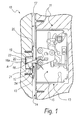
Figure 1 is a sectional view of a lock according to the invention in a configuration for closing the door; -
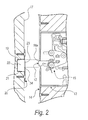
Figure 2 is a sectional view of the lock according to the invention in a configuration for opening the door; -
Figure 3 is a sectional view of the lock according to the invention during a step of installation on the door. - It is noted that anything found to be already known during the patenting process is understood not to be claimed and to be the subject of a disclaimer.
- With reference to the figures, the
reference numeral 10 generally designates a lock, particularly for slidingdoors 11 and the like, which comprises alatch 12 that is supported, so that it can slide and rotate, by amain body 13. - The
main body 13 is associated with aleaf 14 and accommodates means 15 for actuating thelatch 12, which can be operated by the user to pass - from a first configuration, in which the
latch 12 is substantially retracted into themain body 13, - to a second configuration, in which the
latch 12 is extracted from themain body 13, - and vice versa.
- A particularity of the
lock 10 is that thelatch 12 comprises anelement 16 for marking by striking ajamb 17 that supports aretention element 18 for thelatch 12. - A
hole 19 is provided on thejamb 17 and has a substantially circular cross-section with an axis A that is aligned with themarking element 16 when thelatch 12 is in the second configuration. - There is also a
contrast plate 20, which covers thehole 19 partially, is provided with theretention element 18 and is associated with thejamb 17. - The
latch 12, in the second configuration, is inserted in thehole 19 and is engaged with theretention element 18 in order to prevent the spacing of theleaf 14 from thejamb 17, i.e., the opening of the sliding door. - Advantageously, the
latch 12 has apointed nose 16a, which forms the markingelement 16. - Further, the
lock 10 conveniently comprises a cup-shaped element 21 that is inserted in thehole 19 to form acompartment 22 for accommodating thelatch 12. - Conveniently, the
hole 19 is a cylindrical dead hole provided by drilling thejamb 17. - The
contrast plate 20 advantageously has anopening 23 for inserting thelatch 12 in thehole 19, theretention element 18 being formed by aflap 24 of thecontrast plate 20 that is perimetric with respect to the opening 23. - The use of the
lock 10 according to the invention is as follows. - The
main body 13 is associated with aleaf 14 of the slidingdoor 11 and then, once thelatch 12 has been extracted into the second configuration, theleaf 14 is pushed against thejamb 17 so that thelatch 12 marks it with a notch B at itspointed nose 16a. - The
hole 19 for inserting thelatch 12 on thejamb 17 is then provided by drilling, centering the drilling bit on the notch provided in thejamb 17. - In this manner, the
compartment 22 for accommodating thelatch 12, in which the cup-shaped element 21 is thus inserted, is provided. - The
contrast plate 20 is then positioned on thehole 19 for inserting thelatch 12 so as to cover it partially, so that theopening 23 is substantially aligned with thelatch 12 in the first configuration. - In this manner, when the
leaf 14 that supports themain body 13 abuts against thejamb 17, moving thelatch 12 from the first configuration to the second configuration, the latch passes through the opening 23 of thecontrast plate 20 and enters thecompartment 22, engaging theretention element 18 formed by theflap 24 of thecontrast plate 20. - In practice it has been found that the invention achieves the intended aim and objects, providing a lock that allows to provide the latch insertion hole during the installation of the lock easily and precisely without requiring adaptations of the contrast plate for covering the hole to ensure effective closure of the lock.
- The invention thus conceived is susceptible of numerous modifications and variations, all of which are within the scope of the appended claims; all the details may further be replaced with other technically equivalent elements.
- In practice, the materials employed, so long as they are compatible with the specific use, as well as the contingent shapes and dimensions, may be any according to requirements and to the state of the art.
- The disclosures in Italian Patent Application No.
PD2008A000038 - Where technical features mentioned in any claim are followed by reference signs, those reference signs have been included for the sole purpose of increasing the intelligibility of the claims and accordingly such reference signs do not have any limiting effect on the interpretation of each element identified by way of example by such reference signs.
Claims (5)
- A lock, particularly for sliding doors (11) and the like, which comprises a latch (12) supported so that it can slide and rotate by a main body (13) that is associated with a leaf (14) and accommodates means (15) for actuating said latch (12), which can be operated by the user to pass- from a first configuration, in which said latch (12) is substantially retracted into said main body (13),- to a second configuration, in which said latch (12) is extracted from said main body (13),- and vice versa,characterized in that said latch (12) comprises an element (16) for marking by striking a jamb (17) that supports an element (18) for retaining said latch (12), on said jamb (17) there being a hole (19) which has a substantially circular cross-section with its axis (A) aligned with said marking element (16) when said latch (12) is in said second configuration, a contrast plate (20), which partially covers said hole (19) and is provided with said retention element (18), being associated with said jamb (17), said latch (12), in said second configuration, inserted in said hole (19), being engaged with said retention element (18) to prevent the spacing of said leaf (14) from said jamb (17).
- The lock according to claim 1, characterized in that said latch (12) has a pointed nose (16a) that forms said marking element (16).
- The lock according to one or more of the preceding claims, characterized in that it comprises a cup-shaped element (21), which is inserted in said hole (19) and forms an accommodation compartment (22) for said latch (12).
- The lock according to one or more of the preceding claims, characterized in that said hole (19) is a cylindrical dead hole.
- The lock according to one or more of the preceding claims, characterized in that said contrast plate (20) has an opening (23) for the insertion of said latch (12) in said hole (19), said retention element (18) being formed by a flap (24) of said contrast plate (20) that is perimetric with respect to said opening (23).
Priority Applications (1)
| Application Number | Priority Date | Filing Date | Title |
|---|---|---|---|
| MEP-2012-421A ME02023B (en) | 2008-02-05 | 2009-02-02 | Lock particularly for sliding doors and the like |
Applications Claiming Priority (1)
| Application Number | Priority Date | Filing Date | Title |
|---|---|---|---|
| ITPD20080038 ITPD20080038A1 (en) | 2008-02-05 | 2008-02-05 | LOCK STRUCTURE, PARTICULARLY FOR SLIDING AND SIMILAR DOORS |
Publications (3)
| Publication Number | Publication Date |
|---|---|
| EP2088266A2 true EP2088266A2 (en) | 2009-08-12 |
| EP2088266A3 EP2088266A3 (en) | 2011-10-05 |
| EP2088266B1 EP2088266B1 (en) | 2012-07-04 |
Family
ID=40291787
Family Applications (1)
| Application Number | Title | Priority Date | Filing Date |
|---|---|---|---|
| EP20090151867 Active EP2088266B1 (en) | 2008-02-05 | 2009-02-02 | Lock particularly for sliding doors and the like |
Country Status (7)
| Country | Link |
|---|---|
| EP (1) | EP2088266B1 (en) |
| CN (1) | CN101503924B (en) |
| ES (1) | ES2394292T3 (en) |
| IT (1) | ITPD20080038A1 (en) |
| ME (1) | ME02023B (en) |
| RS (1) | RS52456B (en) |
| RU (1) | RU2471949C2 (en) |
Cited By (1)
| Publication number | Priority date | Publication date | Assignee | Title |
|---|---|---|---|---|
| JP2012140837A (en) * | 2011-01-06 | 2012-07-26 | Miwa Lock Co Ltd | Structure of lock receiving member |
Families Citing this family (1)
| Publication number | Priority date | Publication date | Assignee | Title |
|---|---|---|---|---|
| US20210047866A1 (en) * | 2018-04-19 | 2021-02-18 | Hewlett-Packard Development Company, L.P. | Locking mechanisms |
Citations (3)
| Publication number | Priority date | Publication date | Assignee | Title |
|---|---|---|---|---|
| US2784019A (en) * | 1955-07-07 | 1957-03-05 | Lawrence Brothers | Latch mechanism |
| DE4010939A1 (en) * | 1989-04-11 | 1990-10-18 | Volkswagen Ag | Marking fixing holes of one part of lock - involves dowels in fixing holes of other part of lock |
| EP1837464A2 (en) * | 2006-03-20 | 2007-09-26 | Roto Frank Ag | Jig for attaching a lock fitting and method for attaching a lock fitting |
Family Cites Families (4)
| Publication number | Priority date | Publication date | Assignee | Title |
|---|---|---|---|---|
| CN2057202U (en) * | 1989-06-17 | 1990-05-16 | 湖北省宜昌市钢窗厂 | Theft-proof door lock |
| SU1781401A1 (en) * | 1990-04-25 | 1992-12-15 | Anatolij K Petrenko | Face template |
| CN2641230Y (en) * | 2003-08-26 | 2004-09-15 | 杜均全 | Lock |
| FR2897089B3 (en) * | 2006-02-08 | 2008-04-04 | Jean Francois Levasseur | PLATE DOOR ASSEMBLY INSTALLATION JIG |
-
2008
- 2008-02-05 IT ITPD20080038 patent/ITPD20080038A1/en unknown
-
2009
- 2009-02-02 EP EP20090151867 patent/EP2088266B1/en active Active
- 2009-02-02 RS RS20120421A patent/RS52456B/en unknown
- 2009-02-02 ES ES09151867T patent/ES2394292T3/en active Active
- 2009-02-02 ME MEP-2012-421A patent/ME02023B/en unknown
- 2009-02-04 CN CN 200910007092 patent/CN101503924B/en not_active Expired - Fee Related
- 2009-02-04 RU RU2009103795/12A patent/RU2471949C2/en active
Patent Citations (3)
| Publication number | Priority date | Publication date | Assignee | Title |
|---|---|---|---|---|
| US2784019A (en) * | 1955-07-07 | 1957-03-05 | Lawrence Brothers | Latch mechanism |
| DE4010939A1 (en) * | 1989-04-11 | 1990-10-18 | Volkswagen Ag | Marking fixing holes of one part of lock - involves dowels in fixing holes of other part of lock |
| EP1837464A2 (en) * | 2006-03-20 | 2007-09-26 | Roto Frank Ag | Jig for attaching a lock fitting and method for attaching a lock fitting |
Cited By (1)
| Publication number | Priority date | Publication date | Assignee | Title |
|---|---|---|---|---|
| JP2012140837A (en) * | 2011-01-06 | 2012-07-26 | Miwa Lock Co Ltd | Structure of lock receiving member |
Also Published As
| Publication number | Publication date |
|---|---|
| EP2088266A3 (en) | 2011-10-05 |
| ITPD20080038A1 (en) | 2009-08-06 |
| CN101503924A (en) | 2009-08-12 |
| RU2009103795A (en) | 2010-08-10 |
| RU2471949C2 (en) | 2013-01-10 |
| RS52456B (en) | 2013-02-28 |
| CN101503924B (en) | 2013-04-24 |
| EP2088266B1 (en) | 2012-07-04 |
| ES2394292T3 (en) | 2013-01-30 |
| ME02023B (en) | 2013-02-28 |
Similar Documents
| Publication | Publication Date | Title |
|---|---|---|
| US8348308B2 (en) | High security lock for door | |
| US7797973B2 (en) | Hierarchical cylinder lock systems | |
| US9169668B2 (en) | Mortise lock conversion kit for operation with an American cylinder | |
| US4113293A (en) | Adjustable door latch striker | |
| EP2088266B1 (en) | Lock particularly for sliding doors and the like | |
| CN109113449A (en) | Door lock lock pin | |
| US20190017305A1 (en) | Multipoint door locking system | |
| US6889533B2 (en) | Removable keyless turning mechanism for locks | |
| US20160348396A1 (en) | Lock Plate for Spring Lock | |
| US7293439B1 (en) | Combination padlock | |
| US10329802B1 (en) | Lock mechanism | |
| EP3749821B1 (en) | Peripheral assembly for multipoint locks | |
| US9021745B2 (en) | Exit device mount with closed termination | |
| EP2460959A2 (en) | Lockset | |
| EP2455573A1 (en) | Device for suspension fastening of pocket doors positionable in openings smaller than the door | |
| RU2698118C1 (en) | Lock with cylinder mechanism | |
| JP2016041892A (en) | Locking device | |
| CN209837929U (en) | Double-hook lock | |
| EP2532811A1 (en) | Double-bit safety lock | |
| RU159419U1 (en) | CASTLE LOCK "TATI" | |
| ES2571477B1 (en) | Lock and bulb guard against forced opening | |
| KR100611563B1 (en) | A door lock device | |
| KR20130003055U (en) | A lock for windows | |
| KR101218740B1 (en) | A door for crime prevention | |
| KR101051346B1 (en) | Locking apparatus of sliding door |
Legal Events
| Date | Code | Title | Description |
|---|---|---|---|
| PUAI | Public reference made under article 153(3) epc to a published international application that has entered the european phase |
Free format text: ORIGINAL CODE: 0009012 |
|
| AK | Designated contracting states |
Kind code of ref document: A2 Designated state(s): AT BE BG CH CY CZ DE DK EE ES FI FR GB GR HR HU IE IS IT LI LT LU LV MC MK MT NL NO PL PT RO SE SI SK TR |
|
| AX | Request for extension of the european patent |
Extension state: AL BA RS |
|
| PUAL | Search report despatched |
Free format text: ORIGINAL CODE: 0009013 |
|
| AK | Designated contracting states |
Kind code of ref document: A3 Designated state(s): AT BE BG CH CY CZ DE DK EE ES FI FR GB GR HR HU IE IS IT LI LT LU LV MC MK MT NL NO PL PT RO SE SI SK TR |
|
| AX | Request for extension of the european patent |
Extension state: AL BA RS |
|
| RIC1 | Information provided on ipc code assigned before grant |
Ipc: E05B 65/08 20060101AFI20110826BHEP |
|
| 17P | Request for examination filed |
Effective date: 20111115 |
|
| GRAP | Despatch of communication of intention to grant a patent |
Free format text: ORIGINAL CODE: EPIDOSNIGR1 |
|
| GRAS | Grant fee paid |
Free format text: ORIGINAL CODE: EPIDOSNIGR3 |
|
| GRAA | (expected) grant |
Free format text: ORIGINAL CODE: 0009210 |
|
| AKX | Designation fees paid |
Designated state(s): AT BE BG CH CY CZ DE DK EE ES FI FR GB GR HR HU IE IS IT LI LT LU LV MC MK MT NL NO PL PT RO SE SI SK TR |
|
| AXX | Extension fees paid |
Extension state: RS Payment date: 20111115 Extension state: AL Payment date: 20111115 Extension state: BA Payment date: 20111115 |
|
| AK | Designated contracting states |
Kind code of ref document: B1 Designated state(s): AT BE BG CH CY CZ DE DK EE ES FI FR GB GR HR HU IE IS IT LI LT LU LV MC MK MT NL NO PL PT RO SE SI SK TR |
|
| AX | Request for extension of the european patent |
Extension state: AL BA RS |
|
| REG | Reference to a national code |
Ref country code: GB Ref legal event code: FG4D |
|
| REG | Reference to a national code |
Ref country code: CH Ref legal event code: EP |
|
| REG | Reference to a national code |
Ref country code: AT Ref legal event code: REF Ref document number: 565247 Country of ref document: AT Kind code of ref document: T Effective date: 20120715 |
|
| REG | Reference to a national code |
Ref country code: DE Ref legal event code: R082 Ref document number: 602009007969 Country of ref document: DE Representative=s name: KOHLER SCHMID MOEBUS PATENTANWAELTE PARTNERSCH, DE Ref country code: DE Ref legal event code: R082 Ref document number: 602009007969 Country of ref document: DE Representative=s name: KOHLER SCHMID MOEBUS PATENTANWAELTE, DE |
|
| REG | Reference to a national code |
Ref country code: RO Ref legal event code: EPE |
|
| REG | Reference to a national code |
Ref country code: IE Ref legal event code: FG4D |
|
| REG | Reference to a national code |
Ref country code: DE Ref legal event code: R096 Ref document number: 602009007969 Country of ref document: DE Effective date: 20120830 |
|
| REG | Reference to a national code |
Ref country code: AT Ref legal event code: MK05 Ref document number: 565247 Country of ref document: AT Kind code of ref document: T Effective date: 20120704 |
|
| REG | Reference to a national code |
Ref country code: NL Ref legal event code: VDEP Effective date: 20120704 |
|
| PG25 | Lapsed in a contracting state [announced via postgrant information from national office to epo] |
Ref country code: SI Free format text: LAPSE BECAUSE OF FAILURE TO SUBMIT A TRANSLATION OF THE DESCRIPTION OR TO PAY THE FEE WITHIN THE PRESCRIBED TIME-LIMIT Effective date: 20120704 |
|
| REG | Reference to a national code |
Ref country code: LT Ref legal event code: MG4D Effective date: 20120704 |
|
| REG | Reference to a national code |
Ref country code: ES Ref legal event code: FG2A Ref document number: 2394292 Country of ref document: ES Kind code of ref document: T3 Effective date: 20130130 |
|
| PG25 | Lapsed in a contracting state [announced via postgrant information from national office to epo] |
Ref country code: LT Free format text: LAPSE BECAUSE OF FAILURE TO SUBMIT A TRANSLATION OF THE DESCRIPTION OR TO PAY THE FEE WITHIN THE PRESCRIBED TIME-LIMIT Effective date: 20120704 Ref country code: NO Free format text: LAPSE BECAUSE OF FAILURE TO SUBMIT A TRANSLATION OF THE DESCRIPTION OR TO PAY THE FEE WITHIN THE PRESCRIBED TIME-LIMIT Effective date: 20121004 Ref country code: FI Free format text: LAPSE BECAUSE OF FAILURE TO SUBMIT A TRANSLATION OF THE DESCRIPTION OR TO PAY THE FEE WITHIN THE PRESCRIBED TIME-LIMIT Effective date: 20120704 Ref country code: CY Free format text: LAPSE BECAUSE OF FAILURE TO SUBMIT A TRANSLATION OF THE DESCRIPTION OR TO PAY THE FEE WITHIN THE PRESCRIBED TIME-LIMIT Effective date: 20120704 Ref country code: IS Free format text: LAPSE BECAUSE OF FAILURE TO SUBMIT A TRANSLATION OF THE DESCRIPTION OR TO PAY THE FEE WITHIN THE PRESCRIBED TIME-LIMIT Effective date: 20121104 Ref country code: BE Free format text: LAPSE BECAUSE OF FAILURE TO SUBMIT A TRANSLATION OF THE DESCRIPTION OR TO PAY THE FEE WITHIN THE PRESCRIBED TIME-LIMIT Effective date: 20120704 Ref country code: HR Free format text: LAPSE BECAUSE OF FAILURE TO SUBMIT A TRANSLATION OF THE DESCRIPTION OR TO PAY THE FEE WITHIN THE PRESCRIBED TIME-LIMIT Effective date: 20120704 Ref country code: AT Free format text: LAPSE BECAUSE OF FAILURE TO SUBMIT A TRANSLATION OF THE DESCRIPTION OR TO PAY THE FEE WITHIN THE PRESCRIBED TIME-LIMIT Effective date: 20120704 |
|
| PG25 | Lapsed in a contracting state [announced via postgrant information from national office to epo] |
Ref country code: PT Free format text: LAPSE BECAUSE OF FAILURE TO SUBMIT A TRANSLATION OF THE DESCRIPTION OR TO PAY THE FEE WITHIN THE PRESCRIBED TIME-LIMIT Effective date: 20121105 Ref country code: GR Free format text: LAPSE BECAUSE OF FAILURE TO SUBMIT A TRANSLATION OF THE DESCRIPTION OR TO PAY THE FEE WITHIN THE PRESCRIBED TIME-LIMIT Effective date: 20121005 Ref country code: PL Free format text: LAPSE BECAUSE OF FAILURE TO SUBMIT A TRANSLATION OF THE DESCRIPTION OR TO PAY THE FEE WITHIN THE PRESCRIBED TIME-LIMIT Effective date: 20120704 Ref country code: SE Free format text: LAPSE BECAUSE OF FAILURE TO SUBMIT A TRANSLATION OF THE DESCRIPTION OR TO PAY THE FEE WITHIN THE PRESCRIBED TIME-LIMIT Effective date: 20120704 Ref country code: LV Free format text: LAPSE BECAUSE OF FAILURE TO SUBMIT A TRANSLATION OF THE DESCRIPTION OR TO PAY THE FEE WITHIN THE PRESCRIBED TIME-LIMIT Effective date: 20120704 |
|
| PG25 | Lapsed in a contracting state [announced via postgrant information from national office to epo] |
Ref country code: NL Free format text: LAPSE BECAUSE OF FAILURE TO SUBMIT A TRANSLATION OF THE DESCRIPTION OR TO PAY THE FEE WITHIN THE PRESCRIBED TIME-LIMIT Effective date: 20120704 |
|
| PG25 | Lapsed in a contracting state [announced via postgrant information from national office to epo] |
Ref country code: CZ Free format text: LAPSE BECAUSE OF FAILURE TO SUBMIT A TRANSLATION OF THE DESCRIPTION OR TO PAY THE FEE WITHIN THE PRESCRIBED TIME-LIMIT Effective date: 20120704 Ref country code: DK Free format text: LAPSE BECAUSE OF FAILURE TO SUBMIT A TRANSLATION OF THE DESCRIPTION OR TO PAY THE FEE WITHIN THE PRESCRIBED TIME-LIMIT Effective date: 20120704 Ref country code: EE Free format text: LAPSE BECAUSE OF FAILURE TO SUBMIT A TRANSLATION OF THE DESCRIPTION OR TO PAY THE FEE WITHIN THE PRESCRIBED TIME-LIMIT Effective date: 20120704 |
|
| PLBE | No opposition filed within time limit |
Free format text: ORIGINAL CODE: 0009261 |
|
| STAA | Information on the status of an ep patent application or granted ep patent |
Free format text: STATUS: NO OPPOSITION FILED WITHIN TIME LIMIT |
|
| PG25 | Lapsed in a contracting state [announced via postgrant information from national office to epo] |
Ref country code: SK Free format text: LAPSE BECAUSE OF FAILURE TO SUBMIT A TRANSLATION OF THE DESCRIPTION OR TO PAY THE FEE WITHIN THE PRESCRIBED TIME-LIMIT Effective date: 20120704 |
|
| 26N | No opposition filed |
Effective date: 20130405 |
|
| PG25 | Lapsed in a contracting state [announced via postgrant information from national office to epo] |
Ref country code: BG Free format text: LAPSE BECAUSE OF FAILURE TO SUBMIT A TRANSLATION OF THE DESCRIPTION OR TO PAY THE FEE WITHIN THE PRESCRIBED TIME-LIMIT Effective date: 20121004 |
|
| REG | Reference to a national code |
Ref country code: DE Ref legal event code: R097 Ref document number: 602009007969 Country of ref document: DE Effective date: 20130405 |
|
| PG25 | Lapsed in a contracting state [announced via postgrant information from national office to epo] |
Ref country code: MC Free format text: LAPSE BECAUSE OF NON-PAYMENT OF DUE FEES Effective date: 20130228 |
|
| REG | Reference to a national code |
Ref country code: CH Ref legal event code: PL |
|
| GBPC | Gb: european patent ceased through non-payment of renewal fee |
Effective date: 20130202 |
|
| PG25 | Lapsed in a contracting state [announced via postgrant information from national office to epo] |
Ref country code: CH Free format text: LAPSE BECAUSE OF NON-PAYMENT OF DUE FEES Effective date: 20130228 Ref country code: LI Free format text: LAPSE BECAUSE OF NON-PAYMENT OF DUE FEES Effective date: 20130228 |
|
| REG | Reference to a national code |
Ref country code: FR Ref legal event code: ST Effective date: 20131031 |
|
| REG | Reference to a national code |
Ref country code: IE Ref legal event code: MM4A |
|
| PG25 | Lapsed in a contracting state [announced via postgrant information from national office to epo] |
Ref country code: FR Free format text: LAPSE BECAUSE OF NON-PAYMENT OF DUE FEES Effective date: 20130228 Ref country code: GB Free format text: LAPSE BECAUSE OF NON-PAYMENT OF DUE FEES Effective date: 20130202 Ref country code: IE Free format text: LAPSE BECAUSE OF NON-PAYMENT OF DUE FEES Effective date: 20130202 |
|
| PG25 | Lapsed in a contracting state [announced via postgrant information from national office to epo] |
Ref country code: MT Free format text: LAPSE BECAUSE OF FAILURE TO SUBMIT A TRANSLATION OF THE DESCRIPTION OR TO PAY THE FEE WITHIN THE PRESCRIBED TIME-LIMIT Effective date: 20120704 |
|
| PG25 | Lapsed in a contracting state [announced via postgrant information from national office to epo] |
Ref country code: MK Free format text: LAPSE BECAUSE OF FAILURE TO SUBMIT A TRANSLATION OF THE DESCRIPTION OR TO PAY THE FEE WITHIN THE PRESCRIBED TIME-LIMIT Effective date: 20120704 Ref country code: LU Free format text: LAPSE BECAUSE OF NON-PAYMENT OF DUE FEES Effective date: 20130202 Ref country code: HU Free format text: LAPSE BECAUSE OF FAILURE TO SUBMIT A TRANSLATION OF THE DESCRIPTION OR TO PAY THE FEE WITHIN THE PRESCRIBED TIME-LIMIT; INVALID AB INITIO Effective date: 20090202 |
|
| PGFP | Annual fee paid to national office [announced via postgrant information from national office to epo] |
Ref country code: DE Payment date: 20180219 Year of fee payment: 10 |
|
| REG | Reference to a national code |
Ref country code: DE Ref legal event code: R119 Ref document number: 602009007969 Country of ref document: DE |
|
| PG25 | Lapsed in a contracting state [announced via postgrant information from national office to epo] |
Ref country code: DE Free format text: LAPSE BECAUSE OF NON-PAYMENT OF DUE FEES Effective date: 20190903 |
|
| P01 | Opt-out of the competence of the unified patent court (upc) registered |
Effective date: 20230523 |
|
| PGFP | Annual fee paid to national office [announced via postgrant information from national office to epo] |
Ref country code: ES Payment date: 20240307 Year of fee payment: 16 |
|
| PGFP | Annual fee paid to national office [announced via postgrant information from national office to epo] |
Ref country code: RO Payment date: 20240125 Year of fee payment: 16 |
|
| PGFP | Annual fee paid to national office [announced via postgrant information from national office to epo] |
Ref country code: TR Payment date: 20240115 Year of fee payment: 16 Ref country code: IT Payment date: 20240212 Year of fee payment: 16 |