EP2088010A1 - Device for raising the wheels of a vehicle - Google Patents
Device for raising the wheels of a vehicle Download PDFInfo
- Publication number
- EP2088010A1 EP2088010A1 EP09290081A EP09290081A EP2088010A1 EP 2088010 A1 EP2088010 A1 EP 2088010A1 EP 09290081 A EP09290081 A EP 09290081A EP 09290081 A EP09290081 A EP 09290081A EP 2088010 A1 EP2088010 A1 EP 2088010A1
- Authority
- EP
- European Patent Office
- Prior art keywords
- wheels
- lifting
- cylinder
- machine according
- machine
- Prior art date
- Legal status (The legal status is an assumption and is not a legal conclusion. Google has not performed a legal analysis and makes no representation as to the accuracy of the status listed.)
- Granted
Links
Images


Classifications
-
- B—PERFORMING OPERATIONS; TRANSPORTING
- B60—VEHICLES IN GENERAL
- B60G—VEHICLE SUSPENSION ARRANGEMENTS
- B60G17/00—Resilient suspensions having means for adjusting the spring or vibration-damper characteristics, for regulating the distance between a supporting surface and a sprung part of vehicle or for locking suspension during use to meet varying vehicular or surface conditions, e.g. due to speed or load
- B60G17/005—Suspension locking arrangements
-
- B—PERFORMING OPERATIONS; TRANSPORTING
- B60—VEHICLES IN GENERAL
- B60S—SERVICING, CLEANING, REPAIRING, SUPPORTING, LIFTING, OR MANOEUVRING OF VEHICLES, NOT OTHERWISE PROVIDED FOR
- B60S9/00—Ground-engaging vehicle fittings for supporting, lifting, or manoeuvring the vehicle, wholly or in part, e.g. built-in jacks
- B60S9/02—Ground-engaging vehicle fittings for supporting, lifting, or manoeuvring the vehicle, wholly or in part, e.g. built-in jacks for only lifting or supporting
- B60S9/10—Ground-engaging vehicle fittings for supporting, lifting, or manoeuvring the vehicle, wholly or in part, e.g. built-in jacks for only lifting or supporting by fluid pressure
- B60S9/12—Ground-engaging vehicle fittings for supporting, lifting, or manoeuvring the vehicle, wholly or in part, e.g. built-in jacks for only lifting or supporting by fluid pressure of telescopic type
-
- B—PERFORMING OPERATIONS; TRANSPORTING
- B62—LAND VEHICLES FOR TRAVELLING OTHERWISE THAN ON RAILS
- B62D—MOTOR VEHICLES; TRAILERS
- B62D61/00—Motor vehicles or trailers, characterised by the arrangement or number of wheels, not otherwise provided for, e.g. four wheels in diamond pattern
- B62D61/12—Motor vehicles or trailers, characterised by the arrangement or number of wheels, not otherwise provided for, e.g. four wheels in diamond pattern with variable number of ground engaging wheels, e.g. with some wheels arranged higher than others, or with retractable wheels
-
- F—MECHANICAL ENGINEERING; LIGHTING; HEATING; WEAPONS; BLASTING
- F15—FLUID-PRESSURE ACTUATORS; HYDRAULICS OR PNEUMATICS IN GENERAL
- F15B—SYSTEMS ACTING BY MEANS OF FLUIDS IN GENERAL; FLUID-PRESSURE ACTUATORS, e.g. SERVOMOTORS; DETAILS OF FLUID-PRESSURE SYSTEMS, NOT OTHERWISE PROVIDED FOR
- F15B15/00—Fluid-actuated devices for displacing a member from one position to another; Gearing associated therewith
- F15B15/08—Characterised by the construction of the motor unit
- F15B15/14—Characterised by the construction of the motor unit of the straight-cylinder type
- F15B15/1409—Characterised by the construction of the motor unit of the straight-cylinder type with two or more independently movable working pistons
-
- F—MECHANICAL ENGINEERING; LIGHTING; HEATING; WEAPONS; BLASTING
- F41—WEAPONS
- F41A—FUNCTIONAL FEATURES OR DETAILS COMMON TO BOTH SMALLARMS AND ORDNANCE, e.g. CANNONS; MOUNTINGS FOR SMALLARMS OR ORDNANCE
- F41A23/00—Gun mountings, e.g. on vehicles; Disposition of guns on vehicles
- F41A23/28—Wheeled-gun mountings; Endless-track gun mountings
- F41A23/30—Wheeled-gun mountings; Endless-track gun mountings the wheels being liftable from the ground for firing
-
- B—PERFORMING OPERATIONS; TRANSPORTING
- B60—VEHICLES IN GENERAL
- B60G—VEHICLE SUSPENSION ARRANGEMENTS
- B60G2202/00—Indexing codes relating to the type of spring, damper or actuator
- B60G2202/40—Type of actuator
- B60G2202/41—Fluid actuator
-
- B—PERFORMING OPERATIONS; TRANSPORTING
- B60—VEHICLES IN GENERAL
- B60G—VEHICLE SUSPENSION ARRANGEMENTS
- B60G2202/00—Indexing codes relating to the type of spring, damper or actuator
- B60G2202/40—Type of actuator
- B60G2202/42—Electric actuator
-
- B—PERFORMING OPERATIONS; TRANSPORTING
- B60—VEHICLES IN GENERAL
- B60G—VEHICLE SUSPENSION ARRANGEMENTS
- B60G2204/00—Indexing codes related to suspensions per se or to auxiliary parts
- B60G2204/40—Auxiliary suspension parts; Adjustment of suspensions
- B60G2204/47—Means for retracting the suspension
-
- B—PERFORMING OPERATIONS; TRANSPORTING
- B60—VEHICLES IN GENERAL
- B60G—VEHICLE SUSPENSION ARRANGEMENTS
- B60G2300/00—Indexing codes relating to the type of vehicle
- B60G2300/38—Low or lowerable bed vehicles
Definitions
- the technical sector of the present invention is that of devices for lifting the wheels of a vehicle to ensure its stability relative to the ground.
- a trailer or a towed artillery When it is desired to isolate from the ground the wheels of a military or civilian vehicle, a trailer or a towed artillery is implemented means of lifting which provide more or less facilities these operations. These means are always independent damping means. In the case of a towed artillery, it is necessary to implement a platform that must be lowered in order to apply it to the ground which causes the lifting. To carry out these operations, there are always two distinct means which must be provided for the connections with the chassis and the suspension of the vehicle.
- the object of the present invention is to provide a device integrated in a suspension to ensure both the lifting function and the pure suspension function in order to simplify the production of this suspension.
- the invention therefore relates to a device providing the device for lifting the wheels of a machine with wheels, characterized in that it consists of at least one jack whose rod is actuated by at least one side for lifting said wheels and which is also subject to the action of damping means, said cylinder being fixed by its attachment points between the suspension and the frame of said machine.
- the rod is actuated by a hydraulic or pneumatic means for lifting said wheels.
- the hydraulic or pneumatic means is constituted by at least one chamber supplied with fluid to bring the points of attachment of said jack closer together.
- the jack comprises two chambers that can be supplied with fluid to bring the attachment points of said jack closer to or away from said jack with respect to an average intermediate position.
- the body of the jack is fixed to an attachment point via a screw / nut mount for lifting said wheels.
- the screw / nut assembly consists of a worm fixed to an attachment point and a nut fixed to the cylinder body.
- the nut is connected to a reducer whose output is connected to a crank or to a motor means.
- the damping means comprises at least one spring.
- the suspension of the machine is constituted by a double triangulation, the jack being interposed between the frame and one of the triangles.
- the suspension of the machine consists of a pull-arm system, the jack being interposed between the pulled arm and the frame.
- the machine is a vehicle, in particular a military vehicle.
- the machine is a towed artillery.
- the machine is a vehicle, in particular a trailer.
- a first advantage of the device according to the invention lies in the compactness of the suspension without modifying the anchor points.
- Another advantage lies in the lack of modification of the chassis.
- Another advantage lies particularly in the application to a towed artillery where the current fixing points of the suspension are used while ensuring a better stability.
- the device according to the invention applies to any wheeled vehicle which one wishes at the same time ensure the damping function during the rolling and lifting function by a single means. It applies for example to a trailer that must be placed on a fixed platform by retracting the wheels.
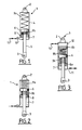
- a monoblock jack 1 provided with its attachment points 2 and 3 to a wheeled vehicle (not shown).
- This jack includes conventionally a body 4 and a rod 5 secured to a piston 6.
- the cylinder 1 comprises an internal chamber 7 whose sealing is provided by a free piston 8 which carries seals.
- This chamber 7 is disposed on one side of the piston 6 so as to reduce by its pressurization the distance between the attachment points 2 and 3.
- the body 4 of the piston encloses a spring 9a disposed between the body 4 and the piston 6, therefore on the opposite side to that of the chamber 7.
- Another spring 9b is disposed between the piston 6 and the free piston 8.
- the chamber 7 is supplied with fluid, air or oil for example, by means of a permanent or temporary connection allowing the connection with a source (not shown) via the pipe 11 As shown in the figure, this pipe is two-way to supply or empty the chamber. In this configuration of the cylinder 1, the chamber 7 is closed and the cylinder is in the damping position.
- the spring 9b ensures the return of the rod 5 and the air volumes (or another gas) surrounding the springs 9a and 9b provide damping of the movements of the rod.
- This configuration is the one adopted in running mode of a vehicle.
- the monoblock cylinder 1 is shown in the raised position, that is to say the position in which a fluid has been injected into the chamber 7 in order to reduce the distance between the two attachment points 2 and 3.
- piston 6 has therefore been pushed by the fluid in translation and has caused compression of the spring 9.
- the jack provides the lifting function which corresponds to a parking configuration of the vehicle or trailer or a firing position for an artillery.
- the piston 1 according to the invention makes it possible to perform two functions, a damping function as represented on the figure 1 and a lifting function as shown on the figure 2 .
- FIG 3 another embodiment of the cylinder 1 according to the invention has been shown in which a second internal chamber 12 has been provided opposite the chamber 7.
- the chamber 12 is arranged facing the free face of the piston 6 and it is connected to a pipe 13 allowing its supply of liquid or gaseous fluid.
- a first free piston 8a is interposed between the chamber 7 and the piston 6 and a second free piston 8b is interposed between the chamber 12 and the piston 6.
- These free pistons carry sealing means.
- a compression spring 9a, 9b is disposed between each free piston 8a, 8b and the piston 6.
- the springs 9a and 9b provide the return function of the cylinder (suspension) and the air volumes (or other gas) surrounding the springs provide damping movements.
- the figure 4 is a schematic representation of the suspension of a towed artillery given by way of example. It can be seen that the wheels 14a and 14b are connected to the artillery frame 15 (not shown) via a double wishbone suspension 16a, 16b and rest on the ground. In the figure, we see that the cylinder 1 is connected to the lower triangle 1b. A platform 17 is fixed rigidly to the frame 15 and this platform is intended to come into contact with the ground when it is desired to stabilize the artillery. In the figure, the jack 1 is in extension maximum as represented on the figure 1 and the spring 9 freely plays its role of shock absorber when the artillery is towed on the road by a vehicle in the driving phase.
- each wheel, 14a for example, is secured to a suspension arm 18 mounted by means of a hinge 21 relative to an interface plate 19 with the frame (not shown).
- the jack 1 represented here is that described in relation to the figure 3 and is supplied with fluid by the pipes 11 and 13, which makes it possible to ensure the three positions of this jack represented on the figure 7 .
- the jack 1 is controlled so as to place the axis of rotation 22 of the wheel 14a in front of the hinge 21.
- the Figure 7 (a) shows the first so-called median rolling position in which the wheel 14a is in contact with the ground.
- the spring 9 then acts as a damper as described above.
- the Figure 7 (b) shows the second position in which the chamber 12 has been powered by causing the extension of the rod 5 of the cylinder 1. This has the effect of bringing the axis 22 of the wheel 14a behind the hinge 21. This second position can move the wheels relative to the center of gravity of the artillery. The axis of the wheels is then substantially vertical to the center of gravity. This arrangement makes it easier to maneuver the artillery when it has been separated from its towing vehicle and to position the artillery according to the firing orders.
- FIG. 7 (c) there is shown the third position of the wheel 14a which has been retracted.
- the chamber 7 of the cylinder was fed through the pipe 11 and causes the approximation of the attachment points of the cylinder.
- the artillery then rests on the ground via the platform 17 (not shown here).
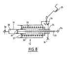
- the jack 1a comprises a body 30 enclosing a spring 32 bearing on a disk 37 integral with a rod 31.
- the rod 31 defines a chamber 38 inside which a rod slides bearing a piston 39.
- the disc 37 slides in the body 30 against the action of a spring 32.
- the latter spring 32 is the spring of the suspension.
- the piston 39 and the chamber 38 here play the role of damper oscillations of the spring 32.
- the rod carrying the piston 39 is fixed and integral with the body 30.
- the spring 32 and the piston assembly 39 / chamber 38 play the role of shock absorber as explained above.
- the body 30 of the jack is connected to the vehicle by a screw / nut assembly which comprises an endless screw 33 in engagement with a nut 34 fixed to the base of this body.
- a gear reducer 36 is provided whose output is connected to a crank 35 or to the axis of a motor.
Abstract
Description
Le secteur technique de la présente invention est celui des dispositifs de relevage des roues d'un véhicule afin d'assurer sa stabilité par rapport au sol.The technical sector of the present invention is that of devices for lifting the wheels of a vehicle to ensure its stability relative to the ground.
Lorsqu'on souhaite isoler du sol les roues d'un véhicule militaire ou civil, d'une remorque ou d'une artillerie tractée on met en oeuvre des moyens de relevage qui assurent avec plus ou moins de facilités ces opérations. Ces moyens sont toujours indépendants des moyens amortisseurs. Dans le cas d'une artillerie tractée, on doit mettre en oeuvre une plate-forme que l'on doit abaisser afin de l'appliquer au sol ce qui provoque le relevage. Pour réaliser ces opérations, on dispose toujours de deux moyens distincts dont il faut prévoir les liaisons avec le châssis et la suspension du véhicule.When it is desired to isolate from the ground the wheels of a military or civilian vehicle, a trailer or a towed artillery is implemented means of lifting which provide more or less facilities these operations. These means are always independent damping means. In the case of a towed artillery, it is necessary to implement a platform that must be lowered in order to apply it to the ground which causes the lifting. To carry out these operations, there are always two distinct means which must be provided for the connections with the chassis and the suspension of the vehicle.
Le but de la présente invention est de fournir un dispositif intégré dans une suspension pour assurer à la fois la fonction relevage et la fonction suspension pure en vue de simplifier la réalisation de cette suspension.The object of the present invention is to provide a device integrated in a suspension to ensure both the lifting function and the pure suspension function in order to simplify the production of this suspension.
L'invention a donc pour objet un dispositif assurant le Dispositif assurant le relevage des roues d'un engin muni de roues, caractérisé en ce qu'il est constitué d'au moins un vérin dont la tige est actionnée d'au moins un côté pour le relevage desdites roues et qui est par ailleurs est soumise à l'action d'un moyen amortisseur, ledit vérin étant fixé par ses points d'attache entre la suspension et le châssis dudit engin.The invention therefore relates to a device providing the device for lifting the wheels of a machine with wheels, characterized in that it consists of at least one jack whose rod is actuated by at least one side for lifting said wheels and which is also subject to the action of damping means, said cylinder being fixed by its attachment points between the suspension and the frame of said machine.
Selon une caractéristique de l'invention, la tige est actionnée par un moyen hydraulique ou pneumatique pour le relevage desdites roues.According to a feature of the invention, the rod is actuated by a hydraulic or pneumatic means for lifting said wheels.
Selon une autre caractéristique de l'invention, le moyen hydraulique ou pneumatique est constitué par au moins une chambre alimentée en fluide pour rapprocher les points d'attache dudit vérin.According to another characteristic of the invention, the hydraulic or pneumatic means is constituted by at least one chamber supplied with fluid to bring the points of attachment of said jack closer together.
Selon encore une autre caractéristique de l'invention, le vérin comporte deux chambres pouvant être alimentées en fluide pour rapprocher ou éloigner les points d'attache dudit vérin par rapport à une position intermédiaire moyenne.According to yet another characteristic of the invention, the jack comprises two chambers that can be supplied with fluid to bring the attachment points of said jack closer to or away from said jack with respect to an average intermediate position.
Selon encore une autre caractéristique de l'invention, le corps du vérin est fixé à un point d'attache par l'intermédiaire d'un montage vis/écrou pour le relevage desdites roues.According to yet another characteristic of the invention, the body of the jack is fixed to an attachment point via a screw / nut mount for lifting said wheels.
Selon encore une autre caractéristique de l'invention, le montage vis/écrou est constitué d'une vis sans fin fixée à un point d'attache et d'un écrou fixé au corps du vérin.According to yet another characteristic of the invention, the screw / nut assembly consists of a worm fixed to an attachment point and a nut fixed to the cylinder body.
Selon encore une autre caractéristique de l'invention, l'écrou est relié à un réducteur dont la sortie est reliée à une manivelle ou à un moyen moteur.According to yet another characteristic of the invention, the nut is connected to a reducer whose output is connected to a crank or to a motor means.
Selon encore une autre caractéristique de l'invention, le moyen amortisseur comprend au moins un ressort.According to yet another characteristic of the invention, the damping means comprises at least one spring.
Selon encore une autre caractéristique de l'invention, la suspension de l'engin est constituée par une double triangulation, le vérin étant interposé entre le châssis et un des triangles.According to yet another characteristic of the invention, the suspension of the machine is constituted by a double triangulation, the jack being interposed between the frame and one of the triangles.
Selon encore une autre caractéristique de l'invention, la suspension de l'engin est constituée d'un système à bras tiré, le vérin étant interposé entre le bras tiré et le châssis.According to yet another characteristic of the invention, the suspension of the machine consists of a pull-arm system, the jack being interposed between the pulled arm and the frame.
Selon encore une autre caractéristique de l'invention, l'engin est un véhicule, en particulier un véhicule militaire.According to yet another characteristic of the invention, the machine is a vehicle, in particular a military vehicle.
Selon encore une autre caractéristique de l'invention, l'engin est une artillerie tractée.According to yet another characteristic of the invention, the machine is a towed artillery.
Selon encore une autre caractéristique de l'invention, l'engin est un véhicule, en particulier une remorque.According to yet another characteristic of the invention, the machine is a vehicle, in particular a trailer.
Un tout premier avantage du dispositif selon l'invention réside dans la compacité de la suspension sans modification des points d'ancrage.A first advantage of the device according to the invention lies in the compactness of the suspension without modifying the anchor points.
Un autre avantage réside dans l'absence de modification du châssis.Another advantage lies in the lack of modification of the chassis.
Un autre avantage réside tout particulièrement dans l'application à une artillerie tractée où on utilise les points de fixation actuels de la suspension tout en assurant une meilleure stabilité.Another advantage lies particularly in the application to a towed artillery where the current fixing points of the suspension are used while ensuring a better stability.
D'autres caractéristiques, détails et avantages de l'invention ressortiront plus clairement de la description donnée ci-après à titre indicatif en relation avec des dessins dans lesquels :
- la
figure 1 représente une coupe du vérin selon un premier mode de réalisation dans sa position d'amortisseur, - la
figure 2 représente une coupe du vérin de lafigure 1 dans sa position relevage, - la
figure 3 représente une coupe du vérin selon un autre mode de réalisation - la
figure 4 est une vue montrant l'intégration du vérin dans une suspension à double triangulation en position d'amortisseur, - la
figure 5 est une vue montrant cette même suspension en position de relevage, - la
figure 6 est une vue montrant l'intégration du vérin dans une suspension à bras tiré, - la
figure 7 représente trois positions possibles du vérin dans la suspension à bras tiré, et - la
figure 8 représente une coupe d'un autre mode de réalisation du vérin.
- the
figure 1 represents a section of the jack according to a first embodiment in its damper position, - the
figure 2 represents a section of the cylinder of thefigure 1 in its lifting position, - the
figure 3 represents a section of the jack according to another embodiment - the
figure 4 is a view showing the integration of the jack in a double-wishbone suspension in the damper position, - the
figure 5 is a view showing this same suspension in the lifting position, - the
figure 6 is a view showing the integration of the jack in a pull-arm suspension, - the
figure 7 represents three possible positions of the jack in the pull-arm suspension, and - the
figure 8 represents a section of another embodiment of the jack.
Dans la description particulière qui va suivre on va décrire l'application à une artillerie tractée, c'est-à-dire un canon monté sur une remorque à roues dont l'essieu est relié au châssis lui-même relié une plate-forme et à deux flèches attelées au véhicule tracteur. Lorsqu'on souhaite mettre cette artillerie en batterie, il faut stabiliser l'arme en abaissant la plate-forme et déployer les flèches dont les extrémités portent des bêches d'ancrage au sol. Cette artillerie est bien connue de l'homme du métier et il n'est pas nécessaire d'en faire une description plus détaillée.In the following particular description, application will be made to a towed artillery, that is to say a gun mounted on a wheeled trailer whose axle is connected to the chassis itself connected to a platform and two arrows coupled to the towing vehicle. When one wishes to put this artillery in battery, it is necessary to stabilize the weapon by lowering the platform and deploy the arrows whose ends carry spades of anchorage on the ground. This artillery is well known to those skilled in the art and it is not necessary to make a more detailed description.
Cependant, il va de soi que le dispositif selon l'invention s'applique à n'importe quel engin à roues dont on désire à la fois assurer la fonction amortisseur lors du roulage et la fonction relevage par un moyen unique. Il s'applique par exemple à une remorque qu'il faut poser sur une plate-forme fixe en escamotant les roues.However, it goes without saying that the device according to the invention applies to any wheeled vehicle which one wishes at the same time ensure the damping function during the rolling and lifting function by a single means. It applies for example to a trailer that must be placed on a fixed platform by retracting the wheels.
Sur la
La chambre 7 est alimentée en fluide, de l'air ou de l'huile par exemple, à l'aide d'un raccord 10 permanent ou temporaire permettant la liaison avec une source (non représentée) par l'intermédiaire de la canalisation 11. Comme représenté sur la figure, cette canalisation est à double sens pour alimenter ou vider la chambre. Dans cette configuration du vérin 1, la chambre 7 est fermée et le vérin est en position d'amortissement. Le ressort 9b assure le rappel de la tige 5 et les volumes d'air (ou d'un autre gaz) entourant les ressorts 9a et 9b assurent l'amortissement des mouvements de la tige. Cette configuration est celle adoptée en mode roulage d'un véhicule.The
Sur la
On voit donc que le piston 1 selon l'invention permet d'assurer deux fonctions, une fonction amortisseur telle que représentée sur la
Sur la
La
Sur la
Avec ce type de suspension à double triangulation, aucune modification du châssis n'est à prévoir puisque le vérin selon l'invention reprend les points de fixation des amortisseurs prévus par le constructeur. On obtient ainsi une meilleure stabilisation et une meilleure répartition des masses. Enfin, l'ouverture des flèches présentes dans ce type d'artillerie tractée est facilitée. Cette réalisation confère donc des avantages importants.With this type of double wishbone suspension, no modification of the chassis is to be expected since the cylinder according to the invention incorporates the attachment points of the dampers provided by the manufacturer. This results in a better stabilization and a better distribution of the masses. Finally, the opening of the arrows present in this type of towed artillery is facilitated. This realization therefore confers important advantages.
Sur la
Là encore avec ce type de suspension, on obtient les mêmes avantages qu'avec la suspension à double triangulation avec toutefois une complexité plus grande du dispositif de relevage.Again with this type of suspension, we obtain the same advantages as the double wishbone suspension with a greater complexity of the lifting device.
La
La
Sur la
Sur la
Bien que la présente description des modes de réalisation soit faite en relation avec une artillerie tractée, on comprend que le dispositif selon l'invention peut être appliqué à tout engin muni de roue sans modification.Although the present description of the embodiments is made in connection with a towed artillery, it is understood that the device according to the invention can be applied to any gear with wheel without modification.
Claims (13)
caractérisé en ce que le moyen amortisseur comprend au moins un ressort (9, 9a, 9b, 32).Device for lifting the wheels of a machine according to any one of the preceding claims,
characterized in that the damping means comprises at least one spring (9, 9a, 9b, 32).
Applications Claiming Priority (1)
| Application Number | Priority Date | Filing Date | Title |
|---|---|---|---|
| FR0800598A FR2927036B1 (en) | 2008-02-05 | 2008-02-05 | DEVICE FOR REARING THE WHEELS OF A GEAR |
Publications (2)
| Publication Number | Publication Date |
|---|---|
| EP2088010A1 true EP2088010A1 (en) | 2009-08-12 |
| EP2088010B1 EP2088010B1 (en) | 2011-07-20 |
Family
ID=39674837
Family Applications (1)
| Application Number | Title | Priority Date | Filing Date |
|---|---|---|---|
| EP09290081A Active EP2088010B1 (en) | 2008-02-05 | 2009-02-04 | Device for raising the wheels of a vehicle |
Country Status (3)
| Country | Link |
|---|---|
| EP (1) | EP2088010B1 (en) |
| AT (1) | ATE516974T1 (en) |
| FR (1) | FR2927036B1 (en) |
Cited By (3)
| Publication number | Priority date | Publication date | Assignee | Title |
|---|---|---|---|---|
| EP2700517A1 (en) * | 2012-08-22 | 2014-02-26 | Diehl BGT Defence GmbH & Co.KG | Wheeled or tracked vehicle with a mounted machine gun which fires shots in rapid sequence |
| WO2017058032A1 (en) * | 2015-09-30 | 2017-04-06 | Eagleton Ip Technology Limited | Improved vehicle |
| IT201700010739A1 (en) * | 2017-02-01 | 2018-08-01 | Roc S R L | HYDRAULIC CYLINDER AND LIFTING GROUP FOR AN AGRICULTURAL MACHINE |
Families Citing this family (3)
| Publication number | Priority date | Publication date | Assignee | Title |
|---|---|---|---|---|
| ITTO20130937A1 (en) * | 2013-11-20 | 2015-05-21 | Cometto Ind | TROLLEY FOR TRAILERS |
| EP4100660A2 (en) * | 2020-02-07 | 2022-12-14 | Timoney Dynamic Solutions Limited | Motor vehicle suspension gas spring |
| US20230227117A1 (en) * | 2022-01-17 | 2023-07-20 | Volvo Truck Corporation | Lifting arrangement for lifting a wheel axle of a vehicle |
Citations (4)
| Publication number | Priority date | Publication date | Assignee | Title |
|---|---|---|---|---|
| GB2250964A (en) * | 1990-12-22 | 1992-06-24 | Lunar Caravans Limited | Wheel lift mechanism for multiple axle vehicle |
| WO1999042311A2 (en) * | 1998-02-23 | 1999-08-26 | General Dynamics Land Systems, Inc. | Adjustable vehicle suspension |
| FR2857301A1 (en) * | 2003-07-11 | 2005-01-14 | Volkswagen Ag | Motor vehicle, has suspension and/or damping device, and lifting device receiving control signal and raising and/or lowering vehicle body in controlled way in optimal accident position |
| FR2865532A1 (en) * | 1988-12-14 | 2005-07-29 | Vickers Shipbuilding & Eng | Light weight field howitzer - includes a barrel which is supported by a cradle constructed from hollow members and which is pivotally mounted about a trunnion bearing secured to a chassis |
-
2008
- 2008-02-05 FR FR0800598A patent/FR2927036B1/en not_active Expired - Fee Related
-
2009
- 2009-02-04 EP EP09290081A patent/EP2088010B1/en active Active
- 2009-02-04 AT AT09290081T patent/ATE516974T1/en not_active IP Right Cessation
Patent Citations (4)
| Publication number | Priority date | Publication date | Assignee | Title |
|---|---|---|---|---|
| FR2865532A1 (en) * | 1988-12-14 | 2005-07-29 | Vickers Shipbuilding & Eng | Light weight field howitzer - includes a barrel which is supported by a cradle constructed from hollow members and which is pivotally mounted about a trunnion bearing secured to a chassis |
| GB2250964A (en) * | 1990-12-22 | 1992-06-24 | Lunar Caravans Limited | Wheel lift mechanism for multiple axle vehicle |
| WO1999042311A2 (en) * | 1998-02-23 | 1999-08-26 | General Dynamics Land Systems, Inc. | Adjustable vehicle suspension |
| FR2857301A1 (en) * | 2003-07-11 | 2005-01-14 | Volkswagen Ag | Motor vehicle, has suspension and/or damping device, and lifting device receiving control signal and raising and/or lowering vehicle body in controlled way in optimal accident position |
Cited By (5)
| Publication number | Priority date | Publication date | Assignee | Title |
|---|---|---|---|---|
| EP2700517A1 (en) * | 2012-08-22 | 2014-02-26 | Diehl BGT Defence GmbH & Co.KG | Wheeled or tracked vehicle with a mounted machine gun which fires shots in rapid sequence |
| EP2700517B1 (en) | 2012-08-22 | 2018-04-11 | Diehl Defence GmbH & Co. KG | Wheeled or tracked vehicle with a mounted machine gun which fires shots in rapid sequence |
| WO2017058032A1 (en) * | 2015-09-30 | 2017-04-06 | Eagleton Ip Technology Limited | Improved vehicle |
| US20180272825A1 (en) * | 2015-09-30 | 2018-09-27 | Eagleton Ip Technology Limited | Improved Vehicle |
| IT201700010739A1 (en) * | 2017-02-01 | 2018-08-01 | Roc S R L | HYDRAULIC CYLINDER AND LIFTING GROUP FOR AN AGRICULTURAL MACHINE |
Also Published As
| Publication number | Publication date |
|---|---|
| EP2088010B1 (en) | 2011-07-20 |
| ATE516974T1 (en) | 2011-08-15 |
| FR2927036B1 (en) | 2010-06-04 |
| FR2927036A1 (en) | 2009-08-07 |
Similar Documents
| Publication | Publication Date | Title |
|---|---|---|
| EP2088010B1 (en) | Device for raising the wheels of a vehicle | |
| EP0176442B1 (en) | Extensible towing hitch for road and rail vehicles | |
| EP1571080B1 (en) | Aircraft engine attachment onto a wing pylon | |
| FR2554415A1 (en) | LANDING DEVICES FOR AIRCRAFT, IN PARTICULAR FOR HELICOPTER | |
| EP0179008B1 (en) | Jacking and damping cylinder and mower provided with such a jacking and damping cylinder | |
| EP0246949A1 (en) | Aircraft landing gear provided with a swivelling beam and having small overall dimensions | |
| FR2565529A1 (en) | SUSPENSION AND / OR DAMPING DEVICE FOR A VEHICLE WHEEL SUPPORT ARM | |
| WO2014060705A2 (en) | Device for assisting the operation of an aircraft door | |
| FR3050496A1 (en) | HYDRAULIC SUSPENSION SYSTEM OF A VEHICLE | |
| FR2868493A1 (en) | SUSPENSION DEVICE WITH HYDRAULIC SHOCK ABSORBER WITH SELECTIVE DAMPING CONTROL | |
| EP3609780B1 (en) | Amphibious vehicle provided with a faired running gear | |
| FR2726230A1 (en) | Automobile wheel unit incorporating hub-mounted driving motor | |
| CH706111A2 (en) | Direction interchangeable module for motorcycle, has steering fork including suspension/ shock absorbers fixed to rocker that is articulated at its middle to steering fork and connected to hydropneumatic suspension device | |
| FR3035351A1 (en) | PNEUMATIC SUSPENSION DEVICE | |
| FR2503082A1 (en) | WHEEL SUSPENSION, IN PARTICULAR FOR MOTORCYCLES | |
| EP0430746B1 (en) | Attachment device, especially for attaching an axle of a rear wheel suspension of a motor vehicle to the body | |
| FR3061087B1 (en) | HYDRAULIC FLOAT CONTROL DEVICE FOR MOTOR VEHICLE AND SUSPENSION AND DAMPING SYSTEM COMPRISING SUCH A DEVICE | |
| EP0236234B1 (en) | Resilient, lockable device forming a variable length bracket | |
| EP1470980A1 (en) | Pneumatic brake booster with reduced operational noise level | |
| FR3047286B1 (en) | MOTOR VEHICLE HYDROPNEUMATIC SUSPENSION CYLINDER AND WHEEL SUSPENSION EQUIPPED WITH SUCH A VERIN | |
| EP0346186A1 (en) | Hydropneumatic suspension device, and vehicle equipped with such a device | |
| FR3050495A1 (en) | HYDRAULIC SUSPENSION SYSTEM OF A VEHICLE | |
| FR2559715A1 (en) | HYDROPNEUMATIC SYSTEM OF ADJUSTABLE HEIGHT FOR A VEHICLE | |
| EP3235696A1 (en) | Actuating device for a trailer brake | |
| EP1193099B1 (en) | Suspension link rod for a motor vehicle drive unit and suspension arrangement comprising same |
Legal Events
| Date | Code | Title | Description |
|---|---|---|---|
| PUAI | Public reference made under article 153(3) epc to a published international application that has entered the european phase |
Free format text: ORIGINAL CODE: 0009012 |
|
| AK | Designated contracting states |
Kind code of ref document: A1 Designated state(s): AT BE BG CH CY CZ DE DK EE ES FI FR GB GR HR HU IE IS IT LI LT LU LV MC MK MT NL NO PL PT RO SE SI SK TR |
|
| AX | Request for extension of the european patent |
Extension state: AL BA RS |
|
| 17P | Request for examination filed |
Effective date: 20100212 |
|
| AKX | Designation fees paid |
Designated state(s): AT BE BG CH CY CZ DE DK EE ES FI FR GB GR HR HU IE IS IT LI LT LU LV MC MK MT NL NO PL PT RO SE SI SK TR |
|
| 17Q | First examination report despatched |
Effective date: 20100331 |
|
| GRAP | Despatch of communication of intention to grant a patent |
Free format text: ORIGINAL CODE: EPIDOSNIGR1 |
|
| GRAS | Grant fee paid |
Free format text: ORIGINAL CODE: EPIDOSNIGR3 |
|
| GRAA | (expected) grant |
Free format text: ORIGINAL CODE: 0009210 |
|
| AK | Designated contracting states |
Kind code of ref document: B1 Designated state(s): AT BE BG CH CY CZ DE DK EE ES FI FR GB GR HR HU IE IS IT LI LT LU LV MC MK MT NL NO PL PT RO SE SI SK TR |
|
| REG | Reference to a national code |
Ref country code: GB Ref legal event code: FG4D Free format text: NOT ENGLISH |
|
| REG | Reference to a national code |
Ref country code: CH Ref legal event code: EP |
|
| REG | Reference to a national code |
Ref country code: DE Ref legal event code: R096 Ref document number: 602009001882 Country of ref document: DE Effective date: 20110915 |
|
| REG | Reference to a national code |
Ref country code: NL Ref legal event code: VDEP Effective date: 20110720 |
|
| REG | Reference to a national code |
Ref country code: AT Ref legal event code: MK05 Ref document number: 516974 Country of ref document: AT Kind code of ref document: T Effective date: 20110720 |
|
| PG25 | Lapsed in a contracting state [announced via postgrant information from national office to epo] |
Ref country code: PT Free format text: LAPSE BECAUSE OF FAILURE TO SUBMIT A TRANSLATION OF THE DESCRIPTION OR TO PAY THE FEE WITHIN THE PRESCRIBED TIME-LIMIT Effective date: 20111121 Ref country code: HR Free format text: LAPSE BECAUSE OF FAILURE TO SUBMIT A TRANSLATION OF THE DESCRIPTION OR TO PAY THE FEE WITHIN THE PRESCRIBED TIME-LIMIT Effective date: 20110720 Ref country code: NO Free format text: LAPSE BECAUSE OF FAILURE TO SUBMIT A TRANSLATION OF THE DESCRIPTION OR TO PAY THE FEE WITHIN THE PRESCRIBED TIME-LIMIT Effective date: 20111020 Ref country code: NL Free format text: LAPSE BECAUSE OF FAILURE TO SUBMIT A TRANSLATION OF THE DESCRIPTION OR TO PAY THE FEE WITHIN THE PRESCRIBED TIME-LIMIT Effective date: 20110720 Ref country code: IS Free format text: LAPSE BECAUSE OF FAILURE TO SUBMIT A TRANSLATION OF THE DESCRIPTION OR TO PAY THE FEE WITHIN THE PRESCRIBED TIME-LIMIT Effective date: 20111120 Ref country code: FI Free format text: LAPSE BECAUSE OF FAILURE TO SUBMIT A TRANSLATION OF THE DESCRIPTION OR TO PAY THE FEE WITHIN THE PRESCRIBED TIME-LIMIT Effective date: 20110720 Ref country code: SE Free format text: LAPSE BECAUSE OF FAILURE TO SUBMIT A TRANSLATION OF THE DESCRIPTION OR TO PAY THE FEE WITHIN THE PRESCRIBED TIME-LIMIT Effective date: 20110720 Ref country code: LT Free format text: LAPSE BECAUSE OF FAILURE TO SUBMIT A TRANSLATION OF THE DESCRIPTION OR TO PAY THE FEE WITHIN THE PRESCRIBED TIME-LIMIT Effective date: 20110720 |
|
| REG | Reference to a national code |
Ref country code: IE Ref legal event code: FD4D |
|
| PG25 | Lapsed in a contracting state [announced via postgrant information from national office to epo] |
Ref country code: GR Free format text: LAPSE BECAUSE OF FAILURE TO SUBMIT A TRANSLATION OF THE DESCRIPTION OR TO PAY THE FEE WITHIN THE PRESCRIBED TIME-LIMIT Effective date: 20111021 Ref country code: CY Free format text: LAPSE BECAUSE OF FAILURE TO SUBMIT A TRANSLATION OF THE DESCRIPTION OR TO PAY THE FEE WITHIN THE PRESCRIBED TIME-LIMIT Effective date: 20110720 Ref country code: PL Free format text: LAPSE BECAUSE OF FAILURE TO SUBMIT A TRANSLATION OF THE DESCRIPTION OR TO PAY THE FEE WITHIN THE PRESCRIBED TIME-LIMIT Effective date: 20110720 Ref country code: AT Free format text: LAPSE BECAUSE OF FAILURE TO SUBMIT A TRANSLATION OF THE DESCRIPTION OR TO PAY THE FEE WITHIN THE PRESCRIBED TIME-LIMIT Effective date: 20110720 Ref country code: LV Free format text: LAPSE BECAUSE OF FAILURE TO SUBMIT A TRANSLATION OF THE DESCRIPTION OR TO PAY THE FEE WITHIN THE PRESCRIBED TIME-LIMIT Effective date: 20110720 Ref country code: SI Free format text: LAPSE BECAUSE OF FAILURE TO SUBMIT A TRANSLATION OF THE DESCRIPTION OR TO PAY THE FEE WITHIN THE PRESCRIBED TIME-LIMIT Effective date: 20110720 |
|
| PG25 | Lapsed in a contracting state [announced via postgrant information from national office to epo] |
Ref country code: SK Free format text: LAPSE BECAUSE OF FAILURE TO SUBMIT A TRANSLATION OF THE DESCRIPTION OR TO PAY THE FEE WITHIN THE PRESCRIBED TIME-LIMIT Effective date: 20110720 Ref country code: IE Free format text: LAPSE BECAUSE OF FAILURE TO SUBMIT A TRANSLATION OF THE DESCRIPTION OR TO PAY THE FEE WITHIN THE PRESCRIBED TIME-LIMIT Effective date: 20110720 Ref country code: CZ Free format text: LAPSE BECAUSE OF FAILURE TO SUBMIT A TRANSLATION OF THE DESCRIPTION OR TO PAY THE FEE WITHIN THE PRESCRIBED TIME-LIMIT Effective date: 20110720 |
|
| PLBE | No opposition filed within time limit |
Free format text: ORIGINAL CODE: 0009261 |
|
| STAA | Information on the status of an ep patent application or granted ep patent |
Free format text: STATUS: NO OPPOSITION FILED WITHIN TIME LIMIT |
|
| PG25 | Lapsed in a contracting state [announced via postgrant information from national office to epo] |
Ref country code: IT Free format text: LAPSE BECAUSE OF FAILURE TO SUBMIT A TRANSLATION OF THE DESCRIPTION OR TO PAY THE FEE WITHIN THE PRESCRIBED TIME-LIMIT Effective date: 20110720 Ref country code: RO Free format text: LAPSE BECAUSE OF FAILURE TO SUBMIT A TRANSLATION OF THE DESCRIPTION OR TO PAY THE FEE WITHIN THE PRESCRIBED TIME-LIMIT Effective date: 20110720 Ref country code: EE Free format text: LAPSE BECAUSE OF FAILURE TO SUBMIT A TRANSLATION OF THE DESCRIPTION OR TO PAY THE FEE WITHIN THE PRESCRIBED TIME-LIMIT Effective date: 20110720 |
|
| 26N | No opposition filed |
Effective date: 20120423 |
|
| PG25 | Lapsed in a contracting state [announced via postgrant information from national office to epo] |
Ref country code: DK Free format text: LAPSE BECAUSE OF FAILURE TO SUBMIT A TRANSLATION OF THE DESCRIPTION OR TO PAY THE FEE WITHIN THE PRESCRIBED TIME-LIMIT Effective date: 20110720 |
|
| REG | Reference to a national code |
Ref country code: DE Ref legal event code: R097 Ref document number: 602009001882 Country of ref document: DE Effective date: 20120423 |
|
| BERE | Be: lapsed |
Owner name: NEXTER SYSTEMS Effective date: 20120228 |
|
| PG25 | Lapsed in a contracting state [announced via postgrant information from national office to epo] |
Ref country code: MC Free format text: LAPSE BECAUSE OF NON-PAYMENT OF DUE FEES Effective date: 20120229 |
|
| REG | Reference to a national code |
Ref country code: DE Ref legal event code: R119 Ref document number: 602009001882 Country of ref document: DE Effective date: 20120901 |
|
| PG25 | Lapsed in a contracting state [announced via postgrant information from national office to epo] |
Ref country code: BE Free format text: LAPSE BECAUSE OF NON-PAYMENT OF DUE FEES Effective date: 20120228 |
|
| PG25 | Lapsed in a contracting state [announced via postgrant information from national office to epo] |
Ref country code: MK Free format text: LAPSE BECAUSE OF FAILURE TO SUBMIT A TRANSLATION OF THE DESCRIPTION OR TO PAY THE FEE WITHIN THE PRESCRIBED TIME-LIMIT Effective date: 20110720 |
|
| PG25 | Lapsed in a contracting state [announced via postgrant information from national office to epo] |
Ref country code: ES Free format text: LAPSE BECAUSE OF FAILURE TO SUBMIT A TRANSLATION OF THE DESCRIPTION OR TO PAY THE FEE WITHIN THE PRESCRIBED TIME-LIMIT Effective date: 20111031 |
|
| PG25 | Lapsed in a contracting state [announced via postgrant information from national office to epo] |
Ref country code: DE Free format text: LAPSE BECAUSE OF NON-PAYMENT OF DUE FEES Effective date: 20120901 Ref country code: BG Free format text: LAPSE BECAUSE OF FAILURE TO SUBMIT A TRANSLATION OF THE DESCRIPTION OR TO PAY THE FEE WITHIN THE PRESCRIBED TIME-LIMIT Effective date: 20111020 |
|
| PG25 | Lapsed in a contracting state [announced via postgrant information from national office to epo] |
Ref country code: MT Free format text: LAPSE BECAUSE OF FAILURE TO SUBMIT A TRANSLATION OF THE DESCRIPTION OR TO PAY THE FEE WITHIN THE PRESCRIBED TIME-LIMIT Effective date: 20110720 |
|
| REG | Reference to a national code |
Ref country code: CH Ref legal event code: PL |
|
| PG25 | Lapsed in a contracting state [announced via postgrant information from national office to epo] |
Ref country code: LI Free format text: LAPSE BECAUSE OF NON-PAYMENT OF DUE FEES Effective date: 20130228 Ref country code: CH Free format text: LAPSE BECAUSE OF NON-PAYMENT OF DUE FEES Effective date: 20130228 |
|
| PG25 | Lapsed in a contracting state [announced via postgrant information from national office to epo] |
Ref country code: TR Free format text: LAPSE BECAUSE OF FAILURE TO SUBMIT A TRANSLATION OF THE DESCRIPTION OR TO PAY THE FEE WITHIN THE PRESCRIBED TIME-LIMIT Effective date: 20110720 |
|
| PG25 | Lapsed in a contracting state [announced via postgrant information from national office to epo] |
Ref country code: LU Free format text: LAPSE BECAUSE OF NON-PAYMENT OF DUE FEES Effective date: 20120204 |
|
| PG25 | Lapsed in a contracting state [announced via postgrant information from national office to epo] |
Ref country code: HU Free format text: LAPSE BECAUSE OF FAILURE TO SUBMIT A TRANSLATION OF THE DESCRIPTION OR TO PAY THE FEE WITHIN THE PRESCRIBED TIME-LIMIT Effective date: 20090204 |
|
| REG | Reference to a national code |
Ref country code: FR Ref legal event code: PLFP Year of fee payment: 8 |
|
| REG | Reference to a national code |
Ref country code: FR Ref legal event code: PLFP Year of fee payment: 9 |
|
| REG | Reference to a national code |
Ref country code: FR Ref legal event code: PLFP Year of fee payment: 10 |
|
| PGFP | Annual fee paid to national office [announced via postgrant information from national office to epo] |
Ref country code: FR Payment date: 20230119 Year of fee payment: 15 |
|
| PGFP | Annual fee paid to national office [announced via postgrant information from national office to epo] |
Ref country code: GB Payment date: 20230121 Year of fee payment: 15 |