EP2087951A2 - Segmented mandrel for high temperature bonding of metallic axisymmetric shells having complex curvatures - Google Patents
Segmented mandrel for high temperature bonding of metallic axisymmetric shells having complex curvatures Download PDFInfo
- Publication number
- EP2087951A2 EP2087951A2 EP09001840A EP09001840A EP2087951A2 EP 2087951 A2 EP2087951 A2 EP 2087951A2 EP 09001840 A EP09001840 A EP 09001840A EP 09001840 A EP09001840 A EP 09001840A EP 2087951 A2 EP2087951 A2 EP 2087951A2
- Authority
- EP
- European Patent Office
- Prior art keywords
- segments
- mandrel
- shell
- segment
- assembly
- Prior art date
- Legal status (The legal status is an assumption and is not a legal conclusion. Google has not performed a legal analysis and makes no representation as to the accuracy of the status listed.)
- Granted
Links
- 238000000034 method Methods 0.000 claims abstract description 35
- 239000002131 composite material Substances 0.000 claims abstract description 25
- 239000000463 material Substances 0.000 claims abstract description 25
- 238000010438 heat treatment Methods 0.000 claims description 8
- 230000001413 cellular effect Effects 0.000 claims 1
- 239000011162 core material Substances 0.000 claims 1
- 239000011257 shell material Substances 0.000 description 102
- RTAQQCXQSZGOHL-UHFFFAOYSA-N Titanium Chemical compound [Ti] RTAQQCXQSZGOHL-UHFFFAOYSA-N 0.000 description 6
- 239000010936 titanium Substances 0.000 description 6
- 229910052719 titanium Inorganic materials 0.000 description 6
- 229910045601 alloy Inorganic materials 0.000 description 5
- 239000000956 alloy Substances 0.000 description 5
- 238000005304 joining Methods 0.000 description 3
- 239000003795 chemical substances by application Substances 0.000 description 2
- 239000000945 filler Substances 0.000 description 2
- 238000004519 manufacturing process Methods 0.000 description 2
- 239000002184 metal Substances 0.000 description 2
- 229910052751 metal Inorganic materials 0.000 description 2
- 238000003466 welding Methods 0.000 description 2
- 244000089486 Phragmites australis subsp australis Species 0.000 description 1
- 238000009792 diffusion process Methods 0.000 description 1
- 230000008030 elimination Effects 0.000 description 1
- 238000003379 elimination reaction Methods 0.000 description 1
- 239000007769 metal material Substances 0.000 description 1
- 238000012986 modification Methods 0.000 description 1
- 230000004048 modification Effects 0.000 description 1
- 230000003647 oxidation Effects 0.000 description 1
- 238000007254 oxidation reaction Methods 0.000 description 1
- 230000002093 peripheral effect Effects 0.000 description 1
- 238000000926 separation method Methods 0.000 description 1
- 239000010935 stainless steel Substances 0.000 description 1
- 229910001220 stainless steel Inorganic materials 0.000 description 1
Images




Classifications
-
- B—PERFORMING OPERATIONS; TRANSPORTING
- B23—MACHINE TOOLS; METAL-WORKING NOT OTHERWISE PROVIDED FOR
- B23K—SOLDERING OR UNSOLDERING; WELDING; CLADDING OR PLATING BY SOLDERING OR WELDING; CUTTING BY APPLYING HEAT LOCALLY, e.g. FLAME CUTTING; WORKING BY LASER BEAM
- B23K20/00—Non-electric welding by applying impact or other pressure, with or without the application of heat, e.g. cladding or plating
- B23K20/002—Non-electric welding by applying impact or other pressure, with or without the application of heat, e.g. cladding or plating specially adapted for particular articles or work
-
- B—PERFORMING OPERATIONS; TRANSPORTING
- B32—LAYERED PRODUCTS
- B32B—LAYERED PRODUCTS, i.e. PRODUCTS BUILT-UP OF STRATA OF FLAT OR NON-FLAT, e.g. CELLULAR OR HONEYCOMB, FORM
- B32B1/00—Layered products having a non-planar shape
-
- B—PERFORMING OPERATIONS; TRANSPORTING
- B23—MACHINE TOOLS; METAL-WORKING NOT OTHERWISE PROVIDED FOR
- B23K—SOLDERING OR UNSOLDERING; WELDING; CLADDING OR PLATING BY SOLDERING OR WELDING; CUTTING BY APPLYING HEAT LOCALLY, e.g. FLAME CUTTING; WORKING BY LASER BEAM
- B23K20/00—Non-electric welding by applying impact or other pressure, with or without the application of heat, e.g. cladding or plating
- B23K20/22—Non-electric welding by applying impact or other pressure, with or without the application of heat, e.g. cladding or plating taking account of the properties of the materials to be welded
-
- Y—GENERAL TAGGING OF NEW TECHNOLOGICAL DEVELOPMENTS; GENERAL TAGGING OF CROSS-SECTIONAL TECHNOLOGIES SPANNING OVER SEVERAL SECTIONS OF THE IPC; TECHNICAL SUBJECTS COVERED BY FORMER USPC CROSS-REFERENCE ART COLLECTIONS [XRACs] AND DIGESTS
- Y10—TECHNICAL SUBJECTS COVERED BY FORMER USPC
- Y10T—TECHNICAL SUBJECTS COVERED BY FORMER US CLASSIFICATION
- Y10T156/00—Adhesive bonding and miscellaneous chemical manufacture
- Y10T156/10—Methods of surface bonding and/or assembly therefor
- Y10T156/1002—Methods of surface bonding and/or assembly therefor with permanent bending or reshaping or surface deformation of self sustaining lamina
- Y10T156/1028—Methods of surface bonding and/or assembly therefor with permanent bending or reshaping or surface deformation of self sustaining lamina by bending, drawing or stretch forming sheet to assume shape of configured lamina while in contact therewith
- Y10T156/103—Encasing or enveloping the configured lamina
-
- Y—GENERAL TAGGING OF NEW TECHNOLOGICAL DEVELOPMENTS; GENERAL TAGGING OF CROSS-SECTIONAL TECHNOLOGIES SPANNING OVER SEVERAL SECTIONS OF THE IPC; TECHNICAL SUBJECTS COVERED BY FORMER USPC CROSS-REFERENCE ART COLLECTIONS [XRACs] AND DIGESTS
- Y10—TECHNICAL SUBJECTS COVERED BY FORMER USPC
- Y10T—TECHNICAL SUBJECTS COVERED BY FORMER US CLASSIFICATION
- Y10T156/00—Adhesive bonding and miscellaneous chemical manufacture
- Y10T156/10—Methods of surface bonding and/or assembly therefor
- Y10T156/1002—Methods of surface bonding and/or assembly therefor with permanent bending or reshaping or surface deformation of self sustaining lamina
- Y10T156/1028—Methods of surface bonding and/or assembly therefor with permanent bending or reshaping or surface deformation of self sustaining lamina by bending, drawing or stretch forming sheet to assume shape of configured lamina while in contact therewith
- Y10T156/1033—Flexible sheet to cylinder lamina
-
- Y—GENERAL TAGGING OF NEW TECHNOLOGICAL DEVELOPMENTS; GENERAL TAGGING OF CROSS-SECTIONAL TECHNOLOGIES SPANNING OVER SEVERAL SECTIONS OF THE IPC; TECHNICAL SUBJECTS COVERED BY FORMER USPC CROSS-REFERENCE ART COLLECTIONS [XRACs] AND DIGESTS
- Y10—TECHNICAL SUBJECTS COVERED BY FORMER USPC
- Y10T—TECHNICAL SUBJECTS COVERED BY FORMER US CLASSIFICATION
- Y10T156/00—Adhesive bonding and miscellaneous chemical manufacture
- Y10T156/10—Methods of surface bonding and/or assembly therefor
- Y10T156/1002—Methods of surface bonding and/or assembly therefor with permanent bending or reshaping or surface deformation of self sustaining lamina
- Y10T156/1036—Bending of one piece blank and joining edges to form article
- Y10T156/1038—Hollow cylinder article
Definitions
- the invention generally relates to tools and equipment for high temperature bonding of complex metallic structures, and more particularly relates to a segmented mandrel for use in bonding metallic components together by the delta-alpha high temperature bonding process to form an axisymmetric shell structure having complex curvatures, and a method of using such a mandrel.
- the delta-alpha high temperature bonding process (also sometimes referred to as the "delta-alpha diffusion bonding process") can be used to bond metallic component layers of hollow axisymmetric structures for use in modem aircraft.
- Such structures can include an open cell or "honeycomb" metallic core and a metallic face sheet covering each opposed face of the core, for example.
- the high temperature bonding process generally includes compressing two or more layered metal components together at an elevated temperature with a bonding alloy disposed between the layered components. The process results in fused joints between the components that secure the layered components together.
- delta-alpha high temperature bonding process has been developed to provide a method of compressing layered shell components together as the layers are heated to a bonding temperature.
- delta-alpha refers to a difference (commonly designated by the Greek character delta " ⁇ ") in coefficients of thermal expansion (or alpha " ⁇ ").
- Such a process is known for bonding axially-symmetric metallic structures, such as multi-layered cylindrical or conical shells.
- One embodiment of the delta-alpha high temperature bonding process is generally described in U.S. Pat. No. 4,429,824 , assigned to Rohr, Inc., for example.
- layered metallic components to be bonded can be positioned around a one-piece inner mandrel constructed of a material having a relatively high coefficient of thermal expansion.
- the outer surface of the inner mandrel is configured to substantially conform to the final shape of the inside of the cylindrical or conical shape of the composite shell.
- a layer of a suitable bonding alloy is disposed between the layered metallic components at locations where the components are to be bonded together.
- the difference between coefficients of thermal expansion of the layered components and the mandrel causes the inner mandrel to thermally expand more than the layered components.
- the expanded mandrel circumferentially stretches and radially presses on the layered shell components, thus compressing the layered components together.
- the bonding alloy fuses the compressed layers together.
- the mandrel contracts in size, and the one-piece inner mandrel can be extracted from one end of the bonded shell, thereby releasing the bonded shell from the mandrel.
- the inside of the resulting bonded multi-layer shell corresponds in shape to the cylindrical or conical shape of the outer surface of the one-piece mandrel.
- the delta-alpha bonding process described above can be used to bond multi-layer shells having relatively simple cylindrical or conical shapes, forming axisymmetric composite shells having complex curvatures by the delta-alpha bonding process presents special challenges.
- complex curvature means having one or more concave and/or convex curvatures, wherein at least one intermediate diameter of the shell is either larger or smaller than both diameters at the ends of the shell.
- the cylindrical or conical shape of the one-piece inner mandrel and the bonded shell permit the inner mandrel to be extracted from at least one open end of the shell.
- the inner mandrel would become entrapped within the bonded shell structure such that a one-piece mandrel could not be extracted from an open end of the shell.
- One solution to this problem is to produce the shell in two or more generally conical or generally cylindrical sections using the bonding process described above, and then joining the sections together end-to-end to form a complete shell.
- Such a multi-section composite shell typically includes at least one intermediate girth seam around the shell's circumference.
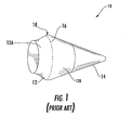
- FIG. 1 shows one example of a typical engine exhaust center plug 10.
- the center plug 10 includes a center body shell 12 and a tail cone 14.
- the center body shell 12 is joined to the tail cone 14 along a circumferential girth seam 16.
- the center body shell 12 has a complex curvature with a maximum diameter at highlight 18 that is larger than the diameter at either end of the shell 12.
- the center body shell 12 must be constructed in at least two longitudinal sections, including a forward shell portion 12A, and an aft shell portion 12B.
- the substantially conical geometry of the forward shell portion 12A permits an inner mandrel portion of corresponding shape used during the delta-alpha bonding process to be extracted from an aft end of the shell portion 12A.
- the substantially conical geometry of the aft shell portion 12B permits an inner mandrel portion of corresponding shape used during the delta-alpha bonding process to be extracted from a forward end of the aft shell portion 12B.
- the forward and aft shell portions 12A, 12B can then be joined along a girth seam 16 as indicated in Fig. 1 by a dashed line.
- the shell portions 12A, 12B then can be joined together along the girth seam 16 using connecting hardware and/or welds in a manner known in the art.
- a multi-piece shell 12 like that described above has several disadvantages.
- the connecting hardware adds weight to the shell assembly 12, and extends the time and cost required to produce the shell 12.
- welding the segments 12A, 12B together along the girth seam 16 adds both cost and time to the production of the shell 12.
- producing two segments 12A and 12B and then joining the segments 12A, 12B together adds to the overall time and cost required to produce the shell 12.
- the invention includes a tool for use in bonding a multi-layer composite shell having complex curvature by the delta-alpha high temperature bonding process.
- the tool can include a plurality of segments that combine to form a mandrel assembly having a longitudinal axis, a lower end, an upper end, and at least one substantially continuous outer surface.
- the outer surface has a substantially axisymmetric shape including a complex curvature.
- a segmented mandrel for use in bonding a composite shell by high temperature bonding includes a first segment, a second segment, and a third segment.
- the first, second, and third segments combine to form at least a portion of a mandrel assembly, such that when the segments are assembled together in substantially edge-to-edge relation and the third segment is disposed between the first and second segments, the first and third segments define a first joint, and the second and third segments define a second joint.
- the mandrel assembly forms at least a portion of a substantially axisymmetric body having a longitudinal axis, a lower end, an upper end, and at least one substantially continuous outer surface having complex curvature.
- the third segment is configured to be movable in a substantially inward direction without substantial obstruction by either the first or second segments.
- the invention also includes a method of bonding a plurality of layered component materials to form an axisymmetric composite shell by high temperature bonding, the composite shell including an exterior surface and an interior surface having complex curvature.
- the method includes assembling the layered component materials to form an unbonded shell assembly.
- the component materials have a first coefficient of thermal expansion.
- a segmented inner mandrel is assembled within the unbonded shell assembly.
- the inner mandrel can include a plurality of segments each having a second coefficient of thermal expansion that is less than the first coefficient of thermal expansion.
- the inner mandrel can include at least one substantially continuous outer surface that substantially corresponds in shape to at least a portion of the interior surface of the composite shell.
- the inner mandrel and the assembled component materials are heated to an elevated temperature, thereby substantially compressing the layered component materials together.
- the segments of the inner mandrel are moved away from the shell to separate the shell from the inner mandrel.
- Fig. 1 is an elevation view of typical exhaust center plug for a modem aircraft engine.
- Fig. 2 is a cutaway perspective view of a typical noise-attenuating panel or shell of a modem aircraft engine structure.
- Fig. 3A is a perspective view of a segmented mandrel assembly with one mandrel segment removed in order to show details of interior portions of the mandrel.
- Fig. 3B is a top plan view of the segmented mandrel assembly shown in Fig. 3A showing all mandrel segments assembled together.
- Fig. 4 is a cross section elevation view of the assembled segmented mandrel shown in Figs. 3A-3B showing a composite shell on the mandrel.
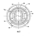
- Fig. 5 is a plan view of the segmented mandrel shown in Figs. 3A-4 showing the upper and lower locking rings, the locking key and locking clips removed, and the two small mandrel segments and the two large mandrel segments moved radially inward.
- Fig. 6 is a cross-sectional elevation view of a large mandrel segment shown in Figs. 3A-5 taken along line 6-6 in Fig. 3B .
- Fig. 7 is side elevation view of a small mandrel segment portion of the segmented mandrel assembly shown in Figs. 3A-5 .
- Fig. 8 is a perspective view of a lifting ring for use with the segmented mandrel assembly shown in Figs. 3A-5 .
- Fig. 9 is a perspective view of a base plate portion of the segmented mandrel shown in Figs. 3A-5 .
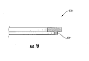
- Fig. 10 is a partial cross-sectional view of the upper locking ring shown in Figs. 3A-3B .
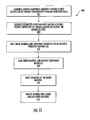
- Fig. 11 is a flow chart showing a method of using a segmented inner mandrel like that shown in Figs. 3A-10 to bond layered components of a metallic shell having complex curvatures.
- a segmented inner mandrel assembly 100 for use in bonding various metallic component materials together to bond a composite shell using the delta-alpha high temperature bonding process is shown in Figs. 3A and 3B .
- the inner mandrel assembly 100 includes a plurality of mandrel segments 110, 120 and 130.
- a fourth mandrel segment (large mandrel segment 140 shown in Fig. 3B ) is removed in Fig. 3A in order to reveal various details of interior portions of the inner mandrel assembly 100.
- the absent mandrel segment 140 is a mirror image of mandrel segment 130.
- the inner mandrel assembly 100 can include a first small mandrel segment 110, and an opposed second small mandrel segment 120.
- the small mandrel segments 110, 120 are mirror images of each other.
- a first small mandrel segment 110 is positioned in edge-to-edge relationship between respective edges 131a, 141b of the large mandrel segments 130, 140.
- a second small mandrel segment 120 is positioned in edge-to-edge relationship between the other respective edges 131b, 141a of the two large mandrel segments 130, 140.
- the adjacent planar edges 111a and 141b, 111b and 131a, 121a and 131b, and 121b and 141 a of the mandrel segments 110, 120, 130 and 140 can be substantially planar, and substantially parallel to each other over substantially their entire lengths.
- the respective edges 111a, 111b, 121a, 121b, 131a, 131b, 141a and 141b of the mandrel segments 110, 120, 130 and 140 are substantially planar, and the gaps between adjacent edges are minimized in order to provide the inner mandrel assembly 100 with a substantially continuous outer surface 115 around its circumference.
- the circumferential gaps between adjacent mandrel segments can be not greater than about 0.005 inch at room temperature.
- the mandrel assembly 100 shown in Fig. 3A also includes a lifting ring 150, a base plate 160, an upper locking ring 170, and a lower locking ring 180.
- Fig. 3A also shows a locking key 190, and a plurality of C-shaped locking clips 195.
- the locking key 190 can be formed as a single circular piece, or can include a plurality of semi-circular segments.
- the upper locking ring 170, lower locking ring 180, locking key 190, and clips 195 work in combination to secure the mandrel segments 110, 120, 130 and 140 in relation to one another in the assembled inner mandrel 100 to form the substantially continuous outer surface 115. As shown in Figs.
- a plurality of station locators 210 can be intermittently positioned around lower peripheral portions of the mandrel segments 110, 120, 130 and 140. As further described below, the station locators 210 provide at least partial vertical support to a composite shell positioned on the inner mandrel assembly 100 during bonding. As shown in Figs. 3A-3B , the lifting ring 150 can include a plurality of spaced lifting lugs 152 for lifting and moving the lifting ring 150 or the mandrel assembly 100.
- the two small mandrel segments 110, 120 for use in the mandrel assembly 100 shown in Figs. 3A and 4 is shown in Fig. 7 .
- the two small mandrel segments 110, 120 are substantially identical, and are interchangeable with each other.
- the small mandrel segments 110, 120 shown in Fig. 7 each include a contoured outer surface 112, 122 having a complex curvature that corresponds in shape to a portion of an interior surface of a shell to be produced using the inner mandrel assembly 100.
- Fig. 7 One embodiment of the two small mandrel segments 110, 120 for use in the mandrel assembly 100 shown in Figs. 3A and 4 is shown in Fig. 7 .
- the two small mandrel segments 110, 120 are substantially identical, and are interchangeable with each other.
- the small mandrel segments 110, 120 shown in Fig. 7 each include a contoured outer surface 112, 122 having a complex curvature that corresponds in shape to a portion
- the small mandrel segments 110, 120 further include a bottom flange 114, 124 and a top flange 116, 126.
- the top flange 116, 126 includes a top circular groove 117, 127.
- the small mandrel segments 110, 120 can each also include an inside rib 118, 128 having a semi-circular groove 119, 129 therealong.
- the small mandrel segments 110, 120 and large mandrel segments 130, 140 can have substantially identical cross-sectional profiles.
- the mandrel segments 110, 120, 130 and 140 are constructed of one or more materials having a first coefficient of thermal expansion.
- the mandrel segments 110, 120, 130 and 140 each can be constructed of creep-resistant stainless steel, or the like, having a first coefficient of thermal expansion.
- the base plate 160 can include an upstanding circular lip 162, and a substantially planar upper support surface 164.
- the upper support surface 164 of the base plate 160 is configured to vertically support and locate the bottom flanges 114, 124, 134, and 144 of the mandrel segments 110, 120, 130 and 140, and the circular lip 162 is configured to establish a circular datum for radially aligning the bottom flanges of the mandrel segments 110, 120, 130 and 140 with each other.
- the external surfaces of the mandrel segments 110, 120, 130 and 140 can be coated with a release agent to prevent unwanted bonding between the mandrel segments and the part being bonded using the mandrel segments.
- the two large mandrel segments 130, 140 are first positioned on opposite sides of the base plate 160.
- the small mandrel segments 110, 120 then can be inserted between the two large mandrel segments 130, 140. As shown in Fig.
- the respective vertical sides 111a, 111b, 121a, 121b, 131a, 131b, 141 a and 141b of the mandrel segments 110, 120, 130 and 140 can be substantially planar and substantially parallel to each other. As described in further detail below, this arrangement permits the small mandrel segments 110, 120 to be moved radially inward and/or radially outward without obstruction by the large mandrel segments 130, 140. Preferably, the gaps between the planar edges of the mandrel segments 110, 120, 130 and 140 are minimized to provide the mandrel assembly with a substantially continuous contoured outer surface 115. For example, the circumferential gaps between adjacent mandrel segments can be about 0.005 inch at room temperature.
- the mandrel segments 110, 120, 130 and 140 are secured together by an upper locking ring 170, a locking key 190 and locking clips 195, and a lower locking ring 180.
- a cross-section of one embodiment of an upper locking ring 170 is shown in Fig. 10 .
- the upper locking ring 170 is a flat circular ring having a downwardly depending circular tongue 172.
- the tongue 172 is sized and shaped to be received in the top grooves 117, 127 of the small mandrel segments 110, 120, and the aligned top grooves 137, 147 of the large mandrel segments 130, 140 (not shown in Fig. 4 ).
- a locking key 190 can be inserted in the semi-circular grooves 119, 129, 139 and 149, and can be secured in place by a plurality of C-shaped clips 195.
- the locking key 190 can include a plurality of semi-circular key segments to facilitate placement of the key 190 in the grooves 119, 129, 139 and 149.
- the key 190 fixes the mid-sections of adjacent mandrel segments 110, 120, 130 and 140 in relationship to each another.
- the lower locking ring 180 is a flat circular ring that is sized to be inserted inside the lower flanges of the mandrel segments 110, 120, 130 and 140. Once so inserted, the lower locking ring 180 blocks radial inward movement of the lower flanges of the mandrel segments 110, 120, 130 and 140, thereby locking the bottoms of the mandrel segments 110, 120, 130 and 140 in relation to one another on the base plate 160.
- the base plate 160 can sit atop a lifting plate 150.
- the lifting plate 150 can include a circular lip 154 for concentrically aligning the base plate 160 on the lifting plate 150.
- the lifting plate 150 also can include a plurality of spaced lifting lugs 152 for use in lifting the assembled mandrel assembly 100 with lifting slings and the like.
- Fig. 4 shows a cross-section of a shell 300 positioned about the contoured outer surface 115 of the inner mandrel assembly 100.
- the outer surface 115 of assembled inner mandrel 100 defines a desired interior contour of the shell 300.
- the shell 300 includes at least two layers of metallic materials and a bonding alloy disposed between those portions of the metallic layers that are to be bonded together.
- the shell 300 can include a titanium inner skin 29, a titanium honeycomb core 24, and a titanium outer skin 27 similar to the shell portion 12 shown in Fig. 2 .
- the inner face skin 29 includes a plurality of spaced perforations 20 that are in acoustic communication with the open cells 22 of the underlying honeycomb core 24.
- the shell 300 and its component materials can be vertically supported on a plurality of circumferentially spaced riser blocks 210 positioned around the bases of the mandrel segments 110, 120, 130 and 140 before, during, and after the component materials are high temperature bonded together about the inner mandrel assembly 100.
- the material of the inner mandrel assembly 100 can be selected such that the material has a coefficient of thermal expansion that is greater than the coefficient of thermal expansion of the layered component shell materials 300.
- a method 400 of using a segmented inner mandrel assembly 100 like that described above to bond an axisymmetric shell 300 having complex curvatures and comprising a plurality of layered metallic component materials by the delta-alpha high temperature bonding process is shown in the flow chart of Fig. 11 .
- the layers of metallic component materials forming the shell are assembled to form an unbonded shell 300.
- the unbonded shell 300 has a shape that substantially coincides with the shape of the outer surface 115 of the mandrel assembly 100.
- the mandrel segments 110, 120, 130 and 140 of a hollow segmented inner mandrel 100 like that shown in Figs. 3A-4 are assembled and locked together.
- the lower edges of the component layers of the unbonded shell 300 can be vertically supported by a plurality of spaced riser blocks 210.
- the inner mandrel 100 and the layered component shell materials 300 are substantially uniformly heated to an elevated bonding temperature.
- a thermal shield can be placed around the shell 300 during heating in order to prevent the shell 300 from being heated too rapidly relative to the mandrel assembly 100.
- the shell 300 and mandrel 100 can be heated to an elevated temperature of about 1,700 degrees Fahrenheit for about 30-120 minutes.
- one or more filler plates 200 can be added to the inner mandrel assembly 100 in order to add additional thermal mass to the assembly, and to facilitate substantially uniform heating of the components.
- the filler plate 200 can be provided to shield the base plate 160 and thereby reduce the heating rate of the relatively thin base plate 160. Because the inner mandrel segments 110, 120, 130 and 140 have a greater coefficient of thermal expansion than the layered component shell materials 300, the layered component shell materials 300 are circumferentially stretched by the mandrel segments 110, 120, 130 and 140 when heated, and the layered component shell materials 300 are radially pressed together by the differential thermal expansion of the inner mandrel 100. Once the mandrel assembly 100 and shell 300 attain an elevated bonding temperature for a sufficient period of time, the bonding alloy disposed between the layers of the shell 300 fuses the shell components together at and along their points and lines of contact.
- the heating can be done in a vacuum or in an inert atmosphere.
- the inner mandrel assembly 100 and shell 300 can be heated to the elevated bonding temperature in a vacuum furnace.
- step 409 the mandrel assembly 100 and shell 300 are slowly and substantially uniformly cooled to about room temperature.
- the difference in the mandrels' coefficient of thermal expansion and the coefficient of thermal expansion of the shell 300 causes the bonded shell 300 to at least partially separate from the inner mandrel 100.
- a release agent can be applied between the mandrel 100 and the shell 300 to facilitate separation of the shell 300 from the mandrel 100.
- the upper locking ring 170, the clips 195 and locking key 190, and the lower locking ring 180 can be removed. Then, the two small mandrel segments 110, 120 can be moved away from the bonded shell 300. In the embodiment shown in Fig. 5 , the small mandrel segments 110, 120 can be moved radially inwardly toward each other and toward the center of the base plate 160. If necessary, the small mandrel segments 110, 120 can be extracted from the mandrel assembly 100 through an open end of the bonded shell 300. Subsequently, the two large mandrel segments 130, 140 can be moved away from interior of the bonded shell.
- the large mandrel segments 130, 140 can be moved radially inwardly toward each other and toward the center of the base plate 160 until all portions of the mandrel segments 110, 120, 130 and 140 lie within a minimum diameter D min of the bonded shell 300.
- the bonded shell 300 can be removed from the collapsed inner mandrel assembly 100.
- the tools and methods described above permit a shell 300 having complex curvatures to be constructed in a single piece, thereby eliminating the need for joining separately formed shell sections together along at least one circumferential girth seam by welding or with connecting hardware. Accordingly, a one-piece shell normally will have a lower weight than a similar two-piece shell. Furthermore, the elimination of connecting hardware reduces the overall part count and weight of the shell. In addition, a one-piece shell can be produced more efficiently and in less time than a multi-segment shell. Furthermore, if the shell is to include acoustic treatment like that shown in Fig. 2 , the one-piece shell maximizes the surface area available for such acoustic treatment
- segmented inner mandrel assembly has been described above as including four separable mandrel segments, the segmented inner mandrel may include more or fewer than four segments.
- segmented inner mandrel assembly has been described as having a substantially convex outer surface, the mandrel can alternatively include a substantially concave outer surface, or an outer surface that includes a combination of at least one substantially convex portion and at least one substantially concave portion. All such variations are intended to be within the scope of the appended claims.
Landscapes
- Engineering & Computer Science (AREA)
- Mechanical Engineering (AREA)
- Pressure Welding/Diffusion-Bonding (AREA)
- Laminated Bodies (AREA)
Abstract
Description
- The invention generally relates to tools and equipment for high temperature bonding of complex metallic structures, and more particularly relates to a segmented mandrel for use in bonding metallic components together by the delta-alpha high temperature bonding process to form an axisymmetric shell structure having complex curvatures, and a method of using such a mandrel.
- The delta-alpha high temperature bonding process (also sometimes referred to as the "delta-alpha diffusion bonding process") can be used to bond metallic component layers of hollow axisymmetric structures for use in modem aircraft. Such structures can include an open cell or "honeycomb" metallic core and a metallic face sheet covering each opposed face of the core, for example. The high temperature bonding process generally includes compressing two or more layered metal components together at an elevated temperature with a bonding alloy disposed between the layered components. The process results in fused joints between the components that secure the layered components together.
- The delta-alpha high temperature bonding process has been developed to provide a method of compressing layered shell components together as the layers are heated to a bonding temperature. The term "delta-alpha" refers to a difference (commonly designated by the Greek character delta "Δ") in coefficients of thermal expansion (or alpha "α"). Such a process is known for bonding axially-symmetric metallic structures, such as multi-layered cylindrical or conical shells. One embodiment of the delta-alpha high temperature bonding process is generally described in
U.S. Pat. No. 4,429,824 , assigned to Rohr, Inc., for example. - To bond a composite shell having a simple cylindrical or simple conical shape using the delta-alpha high temperature bonding process, layered metallic components to be bonded (such as sheets of titanium honeycomb material, titanium face sheets, for example) can be positioned around a one-piece inner mandrel constructed of a material having a relatively high coefficient of thermal expansion. The outer surface of the inner mandrel is configured to substantially conform to the final shape of the inside of the cylindrical or conical shape of the composite shell. A layer of a suitable bonding alloy is disposed between the layered metallic components at locations where the components are to be bonded together. As the layered components and mandrel are heated to an elevated temperature, the difference between coefficients of thermal expansion of the layered components and the mandrel causes the inner mandrel to thermally expand more than the layered components. As a result, the expanded mandrel circumferentially stretches and radially presses on the layered shell components, thus compressing the layered components together. When the metal components are compressed together and heated to a sufficiently high temperature for a sufficient time, the bonding alloy fuses the compressed layers together. As the layered components and mandrel cool, the mandrel contracts in size, and the one-piece inner mandrel can be extracted from one end of the bonded shell, thereby releasing the bonded shell from the mandrel. The inside of the resulting bonded multi-layer shell corresponds in shape to the cylindrical or conical shape of the outer surface of the one-piece mandrel.
- Though the delta-alpha bonding process described above can be used to bond multi-layer shells having relatively simple cylindrical or conical shapes, forming axisymmetric composite shells having complex curvatures by the delta-alpha bonding process presents special challenges. As used herein, the term "complex curvature" means having one or more concave and/or convex curvatures, wherein at least one intermediate diameter of the shell is either larger or smaller than both diameters at the ends of the shell. As described above, after bonding a cylindrical or conical shell, the cylindrical or conical shape of the one-piece inner mandrel and the bonded shell permit the inner mandrel to be extracted from at least one open end of the shell. For shells having non-cylindrical and non-conical complex shapes and substantial convex and or concave curvatures, however, the inner mandrel would become entrapped within the bonded shell structure such that a one-piece mandrel could not be extracted from an open end of the shell. One solution to this problem is to produce the shell in two or more generally conical or generally cylindrical sections using the bonding process described above, and then joining the sections together end-to-end to form a complete shell. Such a multi-section composite shell typically includes at least one intermediate girth seam around the shell's circumference.
- Composite shells like those described above can be used as components of modem aircraft engines. For example, such a composite shell can form at least a portion of an engine's exhaust center plug.
Fig. 1 shows one example of a typical engineexhaust center plug 10. Thecenter plug 10 includes acenter body shell 12 and atail cone 14. Thecenter body shell 12 is joined to thetail cone 14 along acircumferential girth seam 16. Thecenter body shell 12 has a complex curvature with a maximum diameter athighlight 18 that is larger than the diameter at either end of theshell 12. As discussed above, existing methods of bonding a composite shell having complex curvatures using the delta-alpha bonding process dictate that thecenter body shell 12 must be constructed in at least two longitudinal sections, including aforward shell portion 12A, and anaft shell portion 12B. The substantially conical geometry of theforward shell portion 12A permits an inner mandrel portion of corresponding shape used during the delta-alpha bonding process to be extracted from an aft end of theshell portion 12A. Similarly, the substantially conical geometry of theaft shell portion 12B permits an inner mandrel portion of corresponding shape used during the delta-alpha bonding process to be extracted from a forward end of theaft shell portion 12B. The forward andaft shell portions girth seam 16 as indicated inFig. 1 by a dashed line. Theshell portions girth seam 16 using connecting hardware and/or welds in a manner known in the art. - Unfortunately, a
multi-piece shell 12 like that described above has several disadvantages. First, when connecting hardware is used to join theshell segments shell assembly 12, and extends the time and cost required to produce theshell 12. Furthermore, welding thesegments girth seam 16 adds both cost and time to the production of theshell 12. Thus, producing twosegments segments shell 12. Accordingly, there is a need for a method of producing a composite shell having complex curvatures in a single piece, thereby eliminating the need for connecting hardware or girth seam welds, minimizing the overall weight of the resulting axisymmetric structure, reducing the number of parts, and reducing the production time required to produce such axisymmetric composite structures having complex curvatures. - In one embodiment, the invention includes a tool for use in bonding a multi-layer composite shell having complex curvature by the delta-alpha high temperature bonding process. The tool can include a plurality of segments that combine to form a mandrel assembly having a longitudinal axis, a lower end, an upper end, and at least one substantially continuous outer surface. The outer surface has a substantially axisymmetric shape including a complex curvature. When the segments are combined to form the mandrel assembly, at least one of the segments is configured to be movable in a substantially inward direction without substantial obstruction by any other segment.
- In one embodiment, a segmented mandrel for use in bonding a composite shell by high temperature bonding includes a first segment, a second segment, and a third segment. The first, second, and third segments combine to form at least a portion of a mandrel assembly, such that when the segments are assembled together in substantially edge-to-edge relation and the third segment is disposed between the first and second segments, the first and third segments define a first joint, and the second and third segments define a second joint. The mandrel assembly forms at least a portion of a substantially axisymmetric body having a longitudinal axis, a lower end, an upper end, and at least one substantially continuous outer surface having complex curvature. When the first, second, and third segments are assembled together to form the mandrel assembly, the third segment is configured to be movable in a substantially inward direction without substantial obstruction by either the first or second segments.
- The invention also includes a method of bonding a plurality of layered component materials to form an axisymmetric composite shell by high temperature bonding, the composite shell including an exterior surface and an interior surface having complex curvature. In one embodiment, the method includes assembling the layered component materials to form an unbonded shell assembly. The component materials have a first coefficient of thermal expansion. A segmented inner mandrel is assembled within the unbonded shell assembly. The inner mandrel can include a plurality of segments each having a second coefficient of thermal expansion that is less than the first coefficient of thermal expansion. The inner mandrel can include at least one substantially continuous outer surface that substantially corresponds in shape to at least a portion of the interior surface of the composite shell. The inner mandrel and the assembled component materials are heated to an elevated temperature, thereby substantially compressing the layered component materials together. The segments of the inner mandrel are moved away from the shell to separate the shell from the inner mandrel.
- These and other aspects of the invention will be apparent from a reading of the following detailed description together with the drawings.
-
Fig. 1 is an elevation view of typical exhaust center plug for a modem aircraft engine. -
Fig. 2 is a cutaway perspective view of a typical noise-attenuating panel or shell of a modem aircraft engine structure. -
Fig. 3A is a perspective view of a segmented mandrel assembly with one mandrel segment removed in order to show details of interior portions of the mandrel. -
Fig. 3B is a top plan view of the segmented mandrel assembly shown inFig. 3A showing all mandrel segments assembled together. -
Fig. 4 is a cross section elevation view of the assembled segmented mandrel shown inFigs. 3A-3B showing a composite shell on the mandrel. -
Fig. 5 is a plan view of the segmented mandrel shown inFigs. 3A-4 showing the upper and lower locking rings, the locking key and locking clips removed, and the two small mandrel segments and the two large mandrel segments moved radially inward. -
Fig. 6 is a cross-sectional elevation view of a large mandrel segment shown inFigs. 3A-5 taken along line 6-6 inFig. 3B . -
Fig. 7 is side elevation view of a small mandrel segment portion of the segmented mandrel assembly shown inFigs. 3A-5 . -
Fig. 8 is a perspective view of a lifting ring for use with the segmented mandrel assembly shown inFigs. 3A-5 . -
Fig. 9 is a perspective view of a base plate portion of the segmented mandrel shown inFigs. 3A-5 . -
Fig. 10 is a partial cross-sectional view of the upper locking ring shown inFigs. 3A-3B . -
Fig. 11 is a flow chart showing a method of using a segmented inner mandrel like that shown inFigs. 3A-10 to bond layered components of a metallic shell having complex curvatures. - One embodiment of a segmented
inner mandrel assembly 100 for use in bonding various metallic component materials together to bond a composite shell using the delta-alpha high temperature bonding process is shown inFigs. 3A and 3B . In the embodiment shown, theinner mandrel assembly 100 includes a plurality ofmandrel segments large mandrel segment 140 shown inFig. 3B ) is removed inFig. 3A in order to reveal various details of interior portions of theinner mandrel assembly 100. In the embodiment shown inFig. 3A , theabsent mandrel segment 140 is a mirror image ofmandrel segment 130. - As shown in
Figs. 3A and 3B , theinner mandrel assembly 100 can include a firstsmall mandrel segment 110, and an opposed secondsmall mandrel segment 120. In the embodiment shown, thesmall mandrel segments Fig 3B , a firstsmall mandrel segment 110 is positioned in edge-to-edge relationship betweenrespective edges 131a, 141b of thelarge mandrel segments Fig. 3B , a secondsmall mandrel segment 120 is positioned in edge-to-edge relationship between the otherrespective edges large mandrel segments Fig. 3B , the adjacentplanar edges mandrel segments respective edges mandrel segments inner mandrel assembly 100 with a substantially continuousouter surface 115 around its circumference. For example, the circumferential gaps between adjacent mandrel segments can be not greater than about 0.005 inch at room temperature. - The
mandrel assembly 100 shown inFig. 3A also includes alifting ring 150, abase plate 160, anupper locking ring 170, and alower locking ring 180.Fig. 3A also shows a lockingkey 190, and a plurality of C-shaped locking clips 195. The locking key 190 can be formed as a single circular piece, or can include a plurality of semi-circular segments. As further described below, theupper locking ring 170,lower locking ring 180, lockingkey 190, and clips 195 work in combination to secure themandrel segments inner mandrel 100 to form the substantially continuousouter surface 115. As shown inFigs. 3A and4 , a plurality ofstation locators 210 can be intermittently positioned around lower peripheral portions of themandrel segments station locators 210 provide at least partial vertical support to a composite shell positioned on theinner mandrel assembly 100 during bonding. As shown inFigs. 3A-3B , thelifting ring 150 can include a plurality of spaced lifting lugs 152 for lifting and moving thelifting ring 150 or themandrel assembly 100. - One embodiment of the two
small mandrel segments mandrel assembly 100 shown inFigs. 3A and4 is shown inFig. 7 . In this embodiment, the twosmall mandrel segments large mandrel segments Fig. 6 , thesmall mandrel segments Fig. 7 each include a contouredouter surface 112, 122 having a complex curvature that corresponds in shape to a portion of an interior surface of a shell to be produced using theinner mandrel assembly 100. As shown inFig. 7 , thesmall mandrel segments circular groove small mandrel segments semi-circular groove Fig. 6 andFig. 7 , thesmall mandrel segments large mandrel segments mandrel segments mandrel segments - As shown in
Figs. 3A and4 , the twosmall mandrel segments large mandrel segments base plate 160. As shown inFigs. 4 and9 , thebase plate 160 can include an upstandingcircular lip 162, and a substantially planarupper support surface 164. As shown inFigs. 3A and4 , theupper support surface 164 of thebase plate 160 is configured to vertically support and locate the bottom flanges 114, 124, 134, and 144 of themandrel segments circular lip 162 is configured to establish a circular datum for radially aligning the bottom flanges of themandrel segments mandrel 100 is assembled, the external surfaces of themandrel segments inner mandrel assembly 100, the twolarge mandrel segments base plate 160. Thesmall mandrel segments large mandrel segments Fig. 3B , the respectivevertical sides mandrel segments small mandrel segments large mandrel segments mandrel segments outer surface 115. For example, the circumferential gaps between adjacent mandrel segments can be about 0.005 inch at room temperature. - As shown in
Figs. 3A and4 , themandrel segments upper locking ring 170, a lockingkey 190 and lockingclips 195, and alower locking ring 180. A cross-section of one embodiment of anupper locking ring 170 is shown inFig. 10 . In this embodiment, theupper locking ring 170 is a flat circular ring having a downwardly dependingcircular tongue 172. As shown inFig. 4 , thetongue 172 is sized and shaped to be received in thetop grooves small mandrel segments large mandrel segments 130, 140 (not shown inFig. 4 ). Accordingly, thetongue 172 locks the tops of themandrel segments Figs. 3A and4 , a locking key 190 can be inserted in thesemi-circular grooves clips 195. The locking key 190 can include a plurality of semi-circular key segments to facilitate placement of the key 190 in thegrooves adjacent mandrel segments lower locking ring 180 is a flat circular ring that is sized to be inserted inside the lower flanges of themandrel segments lower locking ring 180 blocks radial inward movement of the lower flanges of themandrel segments mandrel segments base plate 160. - As shown in
Figs. 3A and4 , thebase plate 160 can sit atop a liftingplate 150. As shown inFig. 8 , the liftingplate 150 can include acircular lip 154 for concentrically aligning thebase plate 160 on thelifting plate 150. The liftingplate 150 also can include a plurality of spaced lifting lugs 152 for use in lifting the assembledmandrel assembly 100 with lifting slings and the like. -
Fig. 4 shows a cross-section of ashell 300 positioned about the contouredouter surface 115 of theinner mandrel assembly 100. As discussed above, theouter surface 115 of assembledinner mandrel 100 defines a desired interior contour of theshell 300. Theshell 300 includes at least two layers of metallic materials and a bonding alloy disposed between those portions of the metallic layers that are to be bonded together. For example, theshell 300 can include a titaniuminner skin 29, atitanium honeycomb core 24, and a titaniumouter skin 27 similar to theshell portion 12 shown inFig. 2 . In the embodiment shown inFig. 2 , theinner face skin 29 includes a plurality of spacedperforations 20 that are in acoustic communication with theopen cells 22 of theunderlying honeycomb core 24. Such a configuration is known to dissipate or attenuate sound energy that is incident upon theinner face skin 29. As shown inFigs. 3A and4 , theshell 300 and its component materials can be vertically supported on a plurality of circumferentially spaced riser blocks 210 positioned around the bases of themandrel segments inner mandrel assembly 100. In the embodiment shown inFig. 4 , the material of theinner mandrel assembly 100 can be selected such that the material has a coefficient of thermal expansion that is greater than the coefficient of thermal expansion of the layeredcomponent shell materials 300. - One embodiment of a
method 400 of using a segmentedinner mandrel assembly 100 like that described above to bond anaxisymmetric shell 300 having complex curvatures and comprising a plurality of layered metallic component materials by the delta-alpha high temperature bonding process is shown in the flow chart ofFig. 11 . Instep 401, the layers of metallic component materials forming the shell are assembled to form anunbonded shell 300. Theunbonded shell 300 has a shape that substantially coincides with the shape of theouter surface 115 of themandrel assembly 100. Instep 403, themandrel segments inner mandrel 100 like that shown inFigs. 3A-4 are assembled and locked together. As shown inFig. 4 , the lower edges of the component layers of theunbonded shell 300 can be vertically supported by a plurality of spaced riser blocks 210. - In
step 407, theinner mandrel 100 and the layeredcomponent shell materials 300 are substantially uniformly heated to an elevated bonding temperature. If desired, a thermal shield can be placed around theshell 300 during heating in order to prevent theshell 300 from being heated too rapidly relative to themandrel assembly 100. When bonding titanium materials, for example, theshell 300 andmandrel 100 can be heated to an elevated temperature of about 1,700 degrees Fahrenheit for about 30-120 minutes. As shown inFigs. 3A and4 , one ormore filler plates 200 can be added to theinner mandrel assembly 100 in order to add additional thermal mass to the assembly, and to facilitate substantially uniform heating of the components. For example, thefiller plate 200 can be provided to shield thebase plate 160 and thereby reduce the heating rate of the relativelythin base plate 160. Because theinner mandrel segments component shell materials 300, the layeredcomponent shell materials 300 are circumferentially stretched by themandrel segments component shell materials 300 are radially pressed together by the differential thermal expansion of theinner mandrel 100. Once themandrel assembly 100 andshell 300 attain an elevated bonding temperature for a sufficient period of time, the bonding alloy disposed between the layers of theshell 300 fuses the shell components together at and along their points and lines of contact. In order to prevent unwanted oxidation of theshell 300 and the bond interfaces during heating, the heating can be done in a vacuum or in an inert atmosphere. For example, theinner mandrel assembly 100 and shell 300 can be heated to the elevated bonding temperature in a vacuum furnace. - In
step 409, themandrel assembly 100 andshell 300 are slowly and substantially uniformly cooled to about room temperature. As theinner mandrel 100 cools, the difference in the mandrels' coefficient of thermal expansion and the coefficient of thermal expansion of theshell 300 causes the bondedshell 300 to at least partially separate from theinner mandrel 100. As discussed above, a release agent can be applied between themandrel 100 and theshell 300 to facilitate separation of theshell 300 from themandrel 100. Once themandrel 100 andshell 300 have cooled to about room temperature, thesegments inner mandrel assembly 100 can be collapsed or contracted 413 to permit theshell 300 to be removed from theinner mandrel 100. For example, using the embodiment of asegmented mandrel assembly 100 described above and as shown inFig. 5 , theupper locking ring 170, theclips 195 and locking key 190, and thelower locking ring 180 can be removed. Then, the twosmall mandrel segments shell 300. In the embodiment shown inFig. 5 , thesmall mandrel segments base plate 160. If necessary, thesmall mandrel segments mandrel assembly 100 through an open end of the bondedshell 300. Subsequently, the twolarge mandrel segments Fig. 5 , thelarge mandrel segments base plate 160 until all portions of themandrel segments shell 300. In afinal step 415, the bondedshell 300 can be removed from the collapsedinner mandrel assembly 100. - Accordingly, the tools and methods described above permit a
shell 300 having complex curvatures to be constructed in a single piece, thereby eliminating the need for joining separately formed shell sections together along at least one circumferential girth seam by welding or with connecting hardware. Accordingly, a one-piece shell normally will have a lower weight than a similar two-piece shell. Furthermore, the elimination of connecting hardware reduces the overall part count and weight of the shell. In addition, a one-piece shell can be produced more efficiently and in less time than a multi-segment shell. Furthermore, if the shell is to include acoustic treatment like that shown inFig. 2 , the one-piece shell maximizes the surface area available for such acoustic treatment - The embodiments of the invention described above are intended to illustrate and enable various aspects and features of the invention, and are not intended to limit the invention thereto. Persons of ordinary skill in the art will recognize that various changes and modifications can be made to the described embodiments without departing from the invention. For example, though the segmented inner mandrel assembly has been described above as including four separable mandrel segments, the segmented inner mandrel may include more or fewer than four segments. In addition, though the segmented inner mandrel assembly has been described as having a substantially convex outer surface, the mandrel can alternatively include a substantially concave outer surface, or an outer surface that includes a combination of at least one substantially convex portion and at least one substantially concave portion. All such variations are intended to be within the scope of the appended claims.
Claims (21)
- A tool for use in bonding a multi-layer composite shell having complex curvature by the delta-alpha high temperature bonding process, the tool comprising:(a) a plurality of segments that combine to form a mandrel assembly having a longitudinal axis, a lower end, an upper end, and at least one substantially continuous outer surface, the outer surface having a substantially axisymmetric shape including complex curvature;(b) wherein when combined to form the mandrel assembly, at least one of the segments is configured to be movable in a substantially inward direction without substantial obstruction by any other segment.
- A tool according to claim 1 and further comprising a lower support configured to support the plurality of segments at the lower end, and an upper support configured to support the plurality of segments at the upper end.
- A tool according to claim 1 wherein the plurality of segments comprises:(a) first and second segments that are substantially mirror images of each other; and(b) third and fourth segments that are substantially mirror images of each other;(c) wherein the third segment is disposed between the first and second segments, and the fourth segment is positioned between the first and second segments opposite the third segment; and(d) wherein when combined to form the mandrel assembly, both the third and fourth segments can move substantially inwardly without substantial obstruction by the first or second segments
- A tool according to claim 3 wherein the first, second, third and fourth segments include edges that are substantially planar, and that are arranged substantially parallel to each other in the mandrel assembly.
- A tool according to claim 1 and further comprising a rib on an inside portion of each of the plurality of segments, and locking means for holding the ribs and segments in relation to each other as they form the mandrel assembly.
- A tool according to claim 5 wherein the locking means includes at least one key configured to engage adjacent ribs of at least two adjacent segments.
- A segmented mandrel for use in bonding a composite shell by high temperature bonding, the mandrel comprising:(a) a first segment;(b) a second segment; and(c) a third segment;(d) wherein the first, second, and third segments combine to form at least a portion of a mandrel assembly, wherein the segments are assembled together in substantially edge-to-edge relation such that the third segment is disposed between the first and second segments, the first and third segments define a first joint, and the second and third segments define a second joint;(e) wherein the mandrel assembly forms at least a portion of a substantially axisymmetric body having a longitudinal axis, a lower end, an upper end, and at least one substantially continuous outer surface having complex curvature; and(f) wherein when the first, second, and third segments are assembled together to form the mandrel assembly, the third segment is configured to be movable in a substantially inward direction without substantial obstruction by either the first or second segments.
- A mandrel according to claim 7 wherein the first joint is characterized by a first substantially planar interstice, the second joint is characterized by a second substantially planar interstice, and the first and second interstices are substantially parallel to each other.
- A mandrel according to claim 7 wherein the first and second segments are substantially mirror images of each other.
- A mandrel according to claim 7 wherein the first and second segments each form a substantially larger portion of the mandrel assembly than the third segment.
- A mandrel according to claim 7 and further comprising:(a) a fourth segment;(b) wherein the first, second, third and forth segments combine to form the mandrel assembly;(c) wherein the segments are assembled together in substantially edge-to-edge relation such that the fourth segment is disposed between the first and second segments opposite the third segment, the first and fourth segments define a third joint, and the second and fourth segments define a fourth joint;(d) wherein when the first, second, third and fourth segments are assembled together to form the assembly, the fourth segment is configured to be movable in a substantially inward direction without substantial obstruction by either the first or second segments.
- A mandrel according to claim 11 wherein the third joint is characterized by a third substantially planar interstice, the fourth joint is characterized by a fourth substantially planar interstice, and the third and fourth interstices are substantially parallel to each other.
- A mandrel according to claim 12 wherein the first, second, third and fourth interstices are substantially parallel to each other.
- A mandrel according to claim 11 wherein the third and fourth segments are substantially mirror images of each other.
- A mandrel according to claim 11 wherein the first and second segments each comprise a substantially larger portion of the substantially axisymmetric body than either the third segment or the fourth segment.
- A mandrel according to claim 7 and further comprising a lower support configured to support the first, second and third segments in substantially edge-to-edge relation at the lower end, and an upper support configured to support the first, second and third segments in substantially edge-to-edge relation at the upper end.
- A method of bonding a plurality of layered component materials to form an axisymmetric composite shell by high temperature bonding, the composite shell including an exterior surface and an interior surface having complex curvature, the method comprising:(a) assembling the layered component materials to form an unbonded shell assembly, the component materials having a first coefficient of thermal expansion;(b) assembling a segmented inner mandrel within the unbonded shell assembly, the inner mandrel comprising a plurality of segments each having a second coefficient of thermal expansion that is less than the first coefficient of thermal expansion, the inner mandrel having at least one substantially continuous outer surface that substantially corresponds in shape to at least a portion of the interior surface of the composite shell;(c) heating the inner mandrel and the assembled component materials to an elevated temperature, thereby substantially compressing the layered component materials together; and(d) moving the segments of the inner mandrel away from the shell to separate the shell from the inner mandrel.
- A method according to claim 17 wherein the inner mandrel includes at least three segments, and wherein moving the segments includes moving at least one segment in a direction that is substantially toward a center of the inner mandrel.
- A method according to claim 17 wherein at least one of the component materials includes at least one sheet of cellular core material.
- A method according to claim 17 wherein heating the inner mandrel and the assembled component materials to an elevated temperature includes heating in a vacuum.
- A tool for use in forming a hollow multi-layer composite shell having an interior surface with complex curvature by the delta-alpha high temperature bonding process, the tool comprising:(a) an inner mandrel having at least one outer surface, the outer surface substantially corresponding in shape to the complex curvature of the interior surface of the shell; and(b) means for separating portions of the inner mandrel from the interior surface of shell when the shell is bonded together about the outer surface of the inner mandrel.
Applications Claiming Priority (1)
| Application Number | Priority Date | Filing Date | Title |
|---|---|---|---|
| US12/029,170 US8245750B2 (en) | 2008-02-11 | 2008-02-11 | Segmented mandrel for high temperature bonding of metallic axisymmetric shells having complex curvatures |
Publications (3)
| Publication Number | Publication Date |
|---|---|
| EP2087951A2 true EP2087951A2 (en) | 2009-08-12 |
| EP2087951A3 EP2087951A3 (en) | 2009-10-07 |
| EP2087951B1 EP2087951B1 (en) | 2010-08-18 |
Family
ID=40566226
Family Applications (1)
| Application Number | Title | Priority Date | Filing Date |
|---|---|---|---|
| EP09001840A Active EP2087951B1 (en) | 2008-02-11 | 2009-02-10 | Segmented mandrel for high temperature bonding of metallic axisymmetric shells having complex curvatures |
Country Status (4)
| Country | Link |
|---|---|
| US (2) | US8245750B2 (en) |
| EP (1) | EP2087951B1 (en) |
| AT (1) | ATE477865T1 (en) |
| DE (1) | DE602009000107D1 (en) |
Cited By (5)
| Publication number | Priority date | Publication date | Assignee | Title |
|---|---|---|---|---|
| CN102441604A (en) * | 2011-11-24 | 2012-05-09 | 贵州安大航空锻造有限责任公司 | Thermal bulging method for aluminum alloy special-shaped ring rolled piece |
| CN102489615A (en) * | 2011-11-24 | 2012-06-13 | 贵州安大航空锻造有限责任公司 | Thermal bulging process for special-shaped high-temperature-alloy rolled ring workpieces |
| CN102489616A (en) * | 2011-11-24 | 2012-06-13 | 贵州安大航空锻造有限责任公司 | Thermal bulging process for rectangular stainless steel rolled ring workpieces |
| CN102500706A (en) * | 2011-11-24 | 2012-06-20 | 贵州安大航空锻造有限责任公司 | Method for thermally bulging special titanium alloy ring rolled member |
| CN102513456A (en) * | 2011-11-24 | 2012-06-27 | 贵州安大航空锻造有限责任公司 | Thermal bulging method of stainless-steel irregular ring rolled piece |
Families Citing this family (4)
| Publication number | Priority date | Publication date | Assignee | Title |
|---|---|---|---|---|
| US8707747B1 (en) * | 2012-12-14 | 2014-04-29 | Rohr, Inc. | Forming a shaped sandwich panel with a die and a pressure vessel |
| FR3030327B1 (en) * | 2014-12-17 | 2017-07-14 | Aircelle Sa | TOOLS SUITABLE FOR BRAZING A SET OF PARTS |
| US10173348B2 (en) | 2015-09-14 | 2019-01-08 | Bell Helicopter Textron Inc. | Modular mandrel for monolithic composite fuselage |
| US20190091948A1 (en) | 2017-09-26 | 2019-03-28 | Rohr, Inc. | Manufacturing a shaped structural panel with a mandrel and a pressure vessel |
Citations (1)
| Publication number | Priority date | Publication date | Assignee | Title |
|---|---|---|---|---|
| US4429824A (en) | 1981-09-17 | 1984-02-07 | Rohr Industries, Inc. | Delta-alpha bond/superplastic forming method of fabricating titanium structures and the structures resulting therefrom |
Family Cites Families (25)
| Publication number | Priority date | Publication date | Assignee | Title |
|---|---|---|---|---|
| US3184362A (en) * | 1961-03-20 | 1965-05-18 | Fafnir Bearing Co | Apparatus for bonding an annular liner to a bearing ring |
| US3633267A (en) * | 1968-12-27 | 1972-01-11 | Boeing Co | Method of diffusion bonding honeycomb composite structures |
| US4231507A (en) * | 1979-01-09 | 1980-11-04 | The United States Of America As Represented By The United States Department Of Energy | High-temperature, high-pressure bonding of nested tubular metallic components |
| US4355664A (en) * | 1980-07-31 | 1982-10-26 | Raychem Corporation | Apparatus for internal pipe protection |
| US4421589A (en) * | 1982-07-13 | 1983-12-20 | Spire Corporation | Laminator for encapsulating multilayer laminate assembly |
| US4448628A (en) * | 1982-07-14 | 1984-05-15 | Stott Rexeene S | Segmental mandrel for making wound filament structures |
| US4620660A (en) * | 1985-01-24 | 1986-11-04 | Turner William C | Method of manufacturing an internally clad tubular product |
| US4889276A (en) * | 1988-11-07 | 1989-12-26 | Rohr Industries, Inc. | Method and apparatus for forming and bonding metal assemblies |
| SE500363C2 (en) * | 1988-11-14 | 1994-06-13 | Plm Ab | Process of reshaping a preform of plastic material with expandable mandrel |
| US4984732A (en) * | 1989-02-03 | 1991-01-15 | Rohr Industries, Inc. | Method of superplastically forming and diffusion bonding a laminate assembly |
| IT1234126B (en) * | 1989-07-05 | 1992-04-29 | Nowax Srl | STATIC CASE, ESPECIALLY FOR CENTRIFUGAL RADIAL PUMP, AS WELL AS METHOD FOR ITS REALIZATION |
| US5193737A (en) * | 1989-10-12 | 1993-03-16 | General Electric Company | Method and apparatus for diffusion bonding |
| IT1240233B (en) * | 1990-02-02 | 1993-11-27 | Europa Metalli Lmi | PROCEDURE FOR THE PRODUCTION OF MONOLITHIC ELEMENTS CABLES IN METALLIC MATERIAL |
| US5214948A (en) * | 1991-12-18 | 1993-06-01 | The Boeing Company | Forming metal parts using superplastic metal alloys and axial compression |
| US5199631A (en) * | 1992-06-01 | 1993-04-06 | Rohr, Inc. | Differential pressure method and apparatus for bonding high temperature structures |
| US5266137A (en) | 1992-11-10 | 1993-11-30 | Hollingsworth Ritch D | Rigid segmented mandrel with inflatable support |
| NL9301960A (en) | 1993-11-12 | 1995-06-01 | Waal Technology & Consultancy | Device for mechanically expanding a pipe or pipe part. |
| JP2718886B2 (en) | 1993-12-27 | 1998-02-25 | 昭和アルミニウム株式会社 | Tube expansion method of annular extruded profile |
| US5592288A (en) * | 1995-04-28 | 1997-01-07 | Rockwell International Corp. | Method and apparatus for pre-assembling optical components for use with liquid crystal displays |
| JP4154004B2 (en) * | 1997-01-06 | 2008-09-24 | キヤノン株式会社 | Manufacturing method of solar cell module |
| FR2821788B1 (en) * | 2001-03-09 | 2004-04-02 | Eads Airbus Sa | METHOD FOR MANUFACTURING A PANEL WITH A SOUND ACOUSTIC LAYER LAYER AND ACOUSTIC PANEL THUS OBTAINED |
| FR2841494B1 (en) * | 2002-06-27 | 2005-11-25 | Airbus France | KEY MOLDING TOOLS, IN PARTICULAR FOR THE PRODUCTION OF AIR INTAKE WITHOUT ECLISSE |
| JP4608206B2 (en) | 2003-12-22 | 2011-01-12 | 大和製罐株式会社 | Variant can manufacturing method and expandable mold |
| US7049548B1 (en) * | 2005-03-21 | 2006-05-23 | The Boeing Company | System and method for processing a preform vacuum vessel to produce a structural assembly |
| US7707708B2 (en) * | 2005-09-21 | 2010-05-04 | Rohr, Inc. | Apparatus for making a tubular composite structure |
-
2008
- 2008-02-11 US US12/029,170 patent/US8245750B2/en active Active
-
2009
- 2009-02-10 DE DE602009000107T patent/DE602009000107D1/en active Active
- 2009-02-10 EP EP09001840A patent/EP2087951B1/en active Active
- 2009-02-10 AT AT09001840T patent/ATE477865T1/en not_active IP Right Cessation
-
2012
- 2012-07-13 US US13/548,406 patent/US8474684B2/en active Active
Patent Citations (1)
| Publication number | Priority date | Publication date | Assignee | Title |
|---|---|---|---|---|
| US4429824A (en) | 1981-09-17 | 1984-02-07 | Rohr Industries, Inc. | Delta-alpha bond/superplastic forming method of fabricating titanium structures and the structures resulting therefrom |
Cited By (10)
| Publication number | Priority date | Publication date | Assignee | Title |
|---|---|---|---|---|
| CN102441604A (en) * | 2011-11-24 | 2012-05-09 | 贵州安大航空锻造有限责任公司 | Thermal bulging method for aluminum alloy special-shaped ring rolled piece |
| CN102489615A (en) * | 2011-11-24 | 2012-06-13 | 贵州安大航空锻造有限责任公司 | Thermal bulging process for special-shaped high-temperature-alloy rolled ring workpieces |
| CN102489616A (en) * | 2011-11-24 | 2012-06-13 | 贵州安大航空锻造有限责任公司 | Thermal bulging process for rectangular stainless steel rolled ring workpieces |
| CN102500706A (en) * | 2011-11-24 | 2012-06-20 | 贵州安大航空锻造有限责任公司 | Method for thermally bulging special titanium alloy ring rolled member |
| CN102513456A (en) * | 2011-11-24 | 2012-06-27 | 贵州安大航空锻造有限责任公司 | Thermal bulging method of stainless-steel irregular ring rolled piece |
| CN102489615B (en) * | 2011-11-24 | 2014-02-05 | 贵州安大航空锻造有限责任公司 | Thermal bulging process for special-shaped high-temperature-alloy rolled ring workpieces |
| CN102500706B (en) * | 2011-11-24 | 2014-02-05 | 贵州安大航空锻造有限责任公司 | Method for thermally bulging special titanium alloy ring rolled member |
| CN102513456B (en) * | 2011-11-24 | 2014-02-05 | 贵州安大航空锻造有限责任公司 | Thermal bulging method of stainless-steel irregular ring rolled piece |
| CN102441604B (en) * | 2011-11-24 | 2014-02-05 | 贵州安大航空锻造有限责任公司 | Thermal bulging method for aluminum alloy special-shaped ring-rolled piece |
| CN102489616B (en) * | 2011-11-24 | 2014-03-05 | 贵州安大航空锻造有限责任公司 | Thermal Expansion Forming Method of Stainless Steel Rectangular Ring Rolls |
Also Published As
| Publication number | Publication date |
|---|---|
| US8474684B2 (en) | 2013-07-02 |
| EP2087951A3 (en) | 2009-10-07 |
| US20130133820A1 (en) | 2013-05-30 |
| DE602009000107D1 (en) | 2010-09-30 |
| ATE477865T1 (en) | 2010-09-15 |
| EP2087951B1 (en) | 2010-08-18 |
| US8245750B2 (en) | 2012-08-21 |
| US20090199959A1 (en) | 2009-08-13 |
Similar Documents
| Publication | Publication Date | Title |
|---|---|---|
| US8474684B2 (en) | Segmented mandrel for high temperature bonding of metallic axisymmetric shells having complex curvatures | |
| US6692681B1 (en) | Method and apparatus for manufacturing composite structures | |
| US20060231682A1 (en) | Multi-ring system for fuselage barrel formation | |
| RU2466058C2 (en) | Method of producing aircraft fuselage | |
| US9505204B2 (en) | Method for making and joining composite sandwich shell edge joint | |
| US10232463B2 (en) | Tool and method for bonding layers of a metallic axisymmetric structure having complex curvatures | |
| EP3056292B1 (en) | Dual walled titanium tubing and methods of manufacturing the tubing | |
| US8661669B2 (en) | Method of making and joining an aerofoil and root | |
| EP3055087B1 (en) | Method of forming a complexly curved metallic sandwich panel | |
| US6955283B2 (en) | Adaptable mandrel for spin forming | |
| JPH1147859A (en) | Manufacturing method of aluminum alloy panel | |
| CN111151903B (en) | Forming method of titanium alloy hollow cylinder structural member | |
| US12000537B2 (en) | Method of cladding a pressure vessel | |
| US20140299654A1 (en) | Setup for assembling a panel by brazing | |
| JP4044730B2 (en) | Method for producing a metal sheet rotationally symmetric body having a double curved surface and varying thickness | |
| CN107790540B (en) | Method for superplastic forming of a multilayer structure with a monolithic attachment member | |
| JPS6061166A (en) | Production of metallic bellows |
Legal Events
| Date | Code | Title | Description |
|---|---|---|---|
| PUAI | Public reference made under article 153(3) epc to a published international application that has entered the european phase |
Free format text: ORIGINAL CODE: 0009012 |
|
| 17P | Request for examination filed |
Effective date: 20090216 |
|
| AK | Designated contracting states |
Kind code of ref document: A2 Designated state(s): AT BE BG CH CY CZ DE DK EE ES FI FR GB GR HR HU IE IS IT LI LT LU LV MC MK MT NL NO PL PT RO SE SI SK TR |
|
| AX | Request for extension of the european patent |
Extension state: AL BA RS |
|
| PUAL | Search report despatched |
Free format text: ORIGINAL CODE: 0009013 |
|
| AK | Designated contracting states |
Kind code of ref document: A3 Designated state(s): AT BE BG CH CY CZ DE DK EE ES FI FR GB GR HR HU IE IS IT LI LT LU LV MC MK MT NL NO PL PT RO SE SI SK TR |
|
| AX | Request for extension of the european patent |
Extension state: AL BA RS |
|
| RIC1 | Information provided on ipc code assigned before grant |
Ipc: B23K 20/00 20060101ALI20090828BHEP Ipc: B21D 53/92 20060101ALI20090828BHEP Ipc: B21D 39/20 20060101AFI20090511BHEP |
|
| 17Q | First examination report despatched |
Effective date: 20090923 |
|
| GRAP | Despatch of communication of intention to grant a patent |
Free format text: ORIGINAL CODE: EPIDOSNIGR1 |
|
| AKX | Designation fees paid |
Designated state(s): AT BE BG CH CY CZ DE DK EE ES FI FR GB GR HR HU IE IS IT LI LT LU LV MC MK MT NL NO PL PT RO SE SI SK TR |
|
| GRAS | Grant fee paid |
Free format text: ORIGINAL CODE: EPIDOSNIGR3 |
|
| GRAA | (expected) grant |
Free format text: ORIGINAL CODE: 0009210 |
|
| AK | Designated contracting states |
Kind code of ref document: B1 Designated state(s): AT BE BG CH CY CZ DE DK EE ES FI FR GB GR HR HU IE IS IT LI LT LU LV MC MK MT NL NO PL PT RO SE SI SK TR |
|
| REG | Reference to a national code |
Ref country code: GB Ref legal event code: FG4D |
|
| REG | Reference to a national code |
Ref country code: CH Ref legal event code: EP |
|
| REG | Reference to a national code |
Ref country code: IE Ref legal event code: FG4D |
|
| REF | Corresponds to: |
Ref document number: 602009000107 Country of ref document: DE Date of ref document: 20100930 Kind code of ref document: P |
|
| REG | Reference to a national code |
Ref country code: NL Ref legal event code: VDEP Effective date: 20100818 |
|
| LTIE | Lt: invalidation of european patent or patent extension |
Effective date: 20100818 |
|
| PG25 | Lapsed in a contracting state [announced via postgrant information from national office to epo] |
Ref country code: LT Free format text: LAPSE BECAUSE OF FAILURE TO SUBMIT A TRANSLATION OF THE DESCRIPTION OR TO PAY THE FEE WITHIN THE PRESCRIBED TIME-LIMIT Effective date: 20100818 Ref country code: FI Free format text: LAPSE BECAUSE OF FAILURE TO SUBMIT A TRANSLATION OF THE DESCRIPTION OR TO PAY THE FEE WITHIN THE PRESCRIBED TIME-LIMIT Effective date: 20100818 Ref country code: AT Free format text: LAPSE BECAUSE OF FAILURE TO SUBMIT A TRANSLATION OF THE DESCRIPTION OR TO PAY THE FEE WITHIN THE PRESCRIBED TIME-LIMIT Effective date: 20100818 Ref country code: NO Free format text: LAPSE BECAUSE OF FAILURE TO SUBMIT A TRANSLATION OF THE DESCRIPTION OR TO PAY THE FEE WITHIN THE PRESCRIBED TIME-LIMIT Effective date: 20101118 |
|
| PG25 | Lapsed in a contracting state [announced via postgrant information from national office to epo] |
Ref country code: BG Free format text: LAPSE BECAUSE OF FAILURE TO SUBMIT A TRANSLATION OF THE DESCRIPTION OR TO PAY THE FEE WITHIN THE PRESCRIBED TIME-LIMIT Effective date: 20101118 Ref country code: CY Free format text: LAPSE BECAUSE OF FAILURE TO SUBMIT A TRANSLATION OF THE DESCRIPTION OR TO PAY THE FEE WITHIN THE PRESCRIBED TIME-LIMIT Effective date: 20100818 Ref country code: SI Free format text: LAPSE BECAUSE OF FAILURE TO SUBMIT A TRANSLATION OF THE DESCRIPTION OR TO PAY THE FEE WITHIN THE PRESCRIBED TIME-LIMIT Effective date: 20100818 Ref country code: IS Free format text: LAPSE BECAUSE OF FAILURE TO SUBMIT A TRANSLATION OF THE DESCRIPTION OR TO PAY THE FEE WITHIN THE PRESCRIBED TIME-LIMIT Effective date: 20101218 Ref country code: PL Free format text: LAPSE BECAUSE OF FAILURE TO SUBMIT A TRANSLATION OF THE DESCRIPTION OR TO PAY THE FEE WITHIN THE PRESCRIBED TIME-LIMIT Effective date: 20100818 Ref country code: HR Free format text: LAPSE BECAUSE OF FAILURE TO SUBMIT A TRANSLATION OF THE DESCRIPTION OR TO PAY THE FEE WITHIN THE PRESCRIBED TIME-LIMIT Effective date: 20100818 |
|
| PG25 | Lapsed in a contracting state [announced via postgrant information from national office to epo] |
Ref country code: BE Free format text: LAPSE BECAUSE OF FAILURE TO SUBMIT A TRANSLATION OF THE DESCRIPTION OR TO PAY THE FEE WITHIN THE PRESCRIBED TIME-LIMIT Effective date: 20100818 Ref country code: NL Free format text: LAPSE BECAUSE OF FAILURE TO SUBMIT A TRANSLATION OF THE DESCRIPTION OR TO PAY THE FEE WITHIN THE PRESCRIBED TIME-LIMIT Effective date: 20100818 Ref country code: GR Free format text: LAPSE BECAUSE OF FAILURE TO SUBMIT A TRANSLATION OF THE DESCRIPTION OR TO PAY THE FEE WITHIN THE PRESCRIBED TIME-LIMIT Effective date: 20101119 Ref country code: LV Free format text: LAPSE BECAUSE OF FAILURE TO SUBMIT A TRANSLATION OF THE DESCRIPTION OR TO PAY THE FEE WITHIN THE PRESCRIBED TIME-LIMIT Effective date: 20100818 Ref country code: SE Free format text: LAPSE BECAUSE OF FAILURE TO SUBMIT A TRANSLATION OF THE DESCRIPTION OR TO PAY THE FEE WITHIN THE PRESCRIBED TIME-LIMIT Effective date: 20100818 |
|
| PG25 | Lapsed in a contracting state [announced via postgrant information from national office to epo] |
Ref country code: DK Free format text: LAPSE BECAUSE OF FAILURE TO SUBMIT A TRANSLATION OF THE DESCRIPTION OR TO PAY THE FEE WITHIN THE PRESCRIBED TIME-LIMIT Effective date: 20100818 |
|
| PG25 | Lapsed in a contracting state [announced via postgrant information from national office to epo] |
Ref country code: CZ Free format text: LAPSE BECAUSE OF FAILURE TO SUBMIT A TRANSLATION OF THE DESCRIPTION OR TO PAY THE FEE WITHIN THE PRESCRIBED TIME-LIMIT Effective date: 20100818 Ref country code: RO Free format text: LAPSE BECAUSE OF FAILURE TO SUBMIT A TRANSLATION OF THE DESCRIPTION OR TO PAY THE FEE WITHIN THE PRESCRIBED TIME-LIMIT Effective date: 20100818 Ref country code: SK Free format text: LAPSE BECAUSE OF FAILURE TO SUBMIT A TRANSLATION OF THE DESCRIPTION OR TO PAY THE FEE WITHIN THE PRESCRIBED TIME-LIMIT Effective date: 20100818 Ref country code: EE Free format text: LAPSE BECAUSE OF FAILURE TO SUBMIT A TRANSLATION OF THE DESCRIPTION OR TO PAY THE FEE WITHIN THE PRESCRIBED TIME-LIMIT Effective date: 20100818 Ref country code: IT Free format text: LAPSE BECAUSE OF FAILURE TO SUBMIT A TRANSLATION OF THE DESCRIPTION OR TO PAY THE FEE WITHIN THE PRESCRIBED TIME-LIMIT Effective date: 20100818 |
|
| PLBE | No opposition filed within time limit |
Free format text: ORIGINAL CODE: 0009261 |
|
| STAA | Information on the status of an ep patent application or granted ep patent |
Free format text: STATUS: NO OPPOSITION FILED WITHIN TIME LIMIT |
|
| PG25 | Lapsed in a contracting state [announced via postgrant information from national office to epo] |
Ref country code: ES Free format text: LAPSE BECAUSE OF FAILURE TO SUBMIT A TRANSLATION OF THE DESCRIPTION OR TO PAY THE FEE WITHIN THE PRESCRIBED TIME-LIMIT Effective date: 20101129 |
|
| 26N | No opposition filed |
Effective date: 20110519 |
|
| REG | Reference to a national code |
Ref country code: DE Ref legal event code: R097 Ref document number: 602009000107 Country of ref document: DE Effective date: 20110519 |
|
| PG25 | Lapsed in a contracting state [announced via postgrant information from national office to epo] |
Ref country code: MC Free format text: LAPSE BECAUSE OF NON-PAYMENT OF DUE FEES Effective date: 20110228 |
|
| REG | Reference to a national code |
Ref country code: IE Ref legal event code: MM4A |
|
| PG25 | Lapsed in a contracting state [announced via postgrant information from national office to epo] |
Ref country code: MT Free format text: LAPSE BECAUSE OF FAILURE TO SUBMIT A TRANSLATION OF THE DESCRIPTION OR TO PAY THE FEE WITHIN THE PRESCRIBED TIME-LIMIT Effective date: 20100818 |
|
| PG25 | Lapsed in a contracting state [announced via postgrant information from national office to epo] |
Ref country code: IE Free format text: LAPSE BECAUSE OF NON-PAYMENT OF DUE FEES Effective date: 20110210 |
|
| PG25 | Lapsed in a contracting state [announced via postgrant information from national office to epo] |
Ref country code: MK Free format text: LAPSE BECAUSE OF FAILURE TO SUBMIT A TRANSLATION OF THE DESCRIPTION OR TO PAY THE FEE WITHIN THE PRESCRIBED TIME-LIMIT Effective date: 20100818 |
|
| PG25 | Lapsed in a contracting state [announced via postgrant information from national office to epo] |
Ref country code: LU Free format text: LAPSE BECAUSE OF NON-PAYMENT OF DUE FEES Effective date: 20110210 |
|
| PG25 | Lapsed in a contracting state [announced via postgrant information from national office to epo] |
Ref country code: PT Free format text: LAPSE BECAUSE OF NON-PAYMENT OF DUE FEES Effective date: 20100818 |
|
| PG25 | Lapsed in a contracting state [announced via postgrant information from national office to epo] |
Ref country code: TR Free format text: LAPSE BECAUSE OF FAILURE TO SUBMIT A TRANSLATION OF THE DESCRIPTION OR TO PAY THE FEE WITHIN THE PRESCRIBED TIME-LIMIT Effective date: 20100818 |
|
| REG | Reference to a national code |
Ref country code: CH Ref legal event code: PL |
|
| PG25 | Lapsed in a contracting state [announced via postgrant information from national office to epo] |
Ref country code: HU Free format text: LAPSE BECAUSE OF FAILURE TO SUBMIT A TRANSLATION OF THE DESCRIPTION OR TO PAY THE FEE WITHIN THE PRESCRIBED TIME-LIMIT Effective date: 20100818 Ref country code: CH Free format text: LAPSE BECAUSE OF NON-PAYMENT OF DUE FEES Effective date: 20130228 Ref country code: LI Free format text: LAPSE BECAUSE OF NON-PAYMENT OF DUE FEES Effective date: 20130228 |
|
| REG | Reference to a national code |
Ref country code: DE Ref legal event code: R082 Ref document number: 602009000107 Country of ref document: DE Representative=s name: ANDRAE WESTENDORP PATENTANWAELTE PARTNERSCHAFT, DE |
|
| REG | Reference to a national code |
Ref country code: FR Ref legal event code: PLFP Year of fee payment: 8 |
|
| REG | Reference to a national code |
Ref country code: FR Ref legal event code: PLFP Year of fee payment: 9 |
|
| REG | Reference to a national code |
Ref country code: FR Ref legal event code: PLFP Year of fee payment: 10 |
|
| REG | Reference to a national code |
Ref country code: DE Ref legal event code: R082 Ref document number: 602009000107 Country of ref document: DE |
|
| PGFP | Annual fee paid to national office [announced via postgrant information from national office to epo] |
Ref country code: DE Payment date: 20250122 Year of fee payment: 17 |
|
| PGFP | Annual fee paid to national office [announced via postgrant information from national office to epo] |
Ref country code: FR Payment date: 20250121 Year of fee payment: 17 |
|
| PGFP | Annual fee paid to national office [announced via postgrant information from national office to epo] |
Ref country code: GB Payment date: 20250124 Year of fee payment: 17 |