EP2087597B1 - Kaltrauschquellensystem - Google Patents
Kaltrauschquellensystem Download PDFInfo
- Publication number
- EP2087597B1 EP2087597B1 EP07854826.0A EP07854826A EP2087597B1 EP 2087597 B1 EP2087597 B1 EP 2087597B1 EP 07854826 A EP07854826 A EP 07854826A EP 2087597 B1 EP2087597 B1 EP 2087597B1
- Authority
- EP
- European Patent Office
- Prior art keywords
- thermal radiation
- signal
- antenna
- radiation signal
- thermal
- Prior art date
- Legal status (The legal status is an assumption and is not a legal conclusion. Google has not performed a legal analysis and makes no representation as to the accuracy of the status listed.)
- Not-in-force
Links
- 230000005855 radiation Effects 0.000 claims description 97
- 238000000034 method Methods 0.000 claims description 17
- 230000005670 electromagnetic radiation Effects 0.000 claims description 13
- 238000001514 detection method Methods 0.000 claims description 9
- 239000000284 extract Substances 0.000 claims description 7
- 230000004044 response Effects 0.000 claims description 3
- 238000004891 communication Methods 0.000 description 6
- 230000005540 biological transmission Effects 0.000 description 4
- 230000003595 spectral effect Effects 0.000 description 3
- 238000007792 addition Methods 0.000 description 2
- 238000003384 imaging method Methods 0.000 description 2
- 238000012986 modification Methods 0.000 description 2
- 230000004048 modification Effects 0.000 description 2
- 230000035515 penetration Effects 0.000 description 2
- 230000004075 alteration Effects 0.000 description 1
- 238000013459 approach Methods 0.000 description 1
- 230000008859 change Effects 0.000 description 1
- 239000004020 conductor Substances 0.000 description 1
- 230000008878 coupling Effects 0.000 description 1
- 238000010168 coupling process Methods 0.000 description 1
- 238000005859 coupling reaction Methods 0.000 description 1
- 230000001419 dependent effect Effects 0.000 description 1
- 238000013461 design Methods 0.000 description 1
- 230000007613 environmental effect Effects 0.000 description 1
- 230000010354 integration Effects 0.000 description 1
- 238000013178 mathematical model Methods 0.000 description 1
- 230000035945 sensitivity Effects 0.000 description 1
- 238000000926 separation method Methods 0.000 description 1
- 239000007787 solid Substances 0.000 description 1
- 238000001228 spectrum Methods 0.000 description 1
- 238000006467 substitution reaction Methods 0.000 description 1
- 229910000859 α-Fe Inorganic materials 0.000 description 1
Images



Classifications
-
- G—PHYSICS
- G01—MEASURING; TESTING
- G01S—RADIO DIRECTION-FINDING; RADIO NAVIGATION; DETERMINING DISTANCE OR VELOCITY BY USE OF RADIO WAVES; LOCATING OR PRESENCE-DETECTING BY USE OF THE REFLECTION OR RERADIATION OF RADIO WAVES; ANALOGOUS ARRANGEMENTS USING OTHER WAVES
- G01S13/00—Systems using the reflection or reradiation of radio waves, e.g. radar systems; Analogous systems using reflection or reradiation of waves whose nature or wavelength is irrelevant or unspecified
- G01S13/02—Systems using reflection of radio waves, e.g. primary radar systems; Analogous systems
- G01S13/04—Systems determining presence of a target
-
- H—ELECTRICITY
- H04—ELECTRIC COMMUNICATION TECHNIQUE
- H04B—TRANSMISSION
- H04B13/00—Transmission systems characterised by the medium used for transmission, not provided for in groups H04B3/00 - H04B11/00
Definitions
- This disclosure generally relates to communication devices, and more particularly to a system using a cold noise source and a method of operating the same.
- Radiometers measure electro-magnetic radiation emitted from an object.
- Millimeter wave radiometers generally measure electro-magnetic radiation in the millimeter frequency range, typically at wavelengths above microwave bands and below the infrared radiation spectrum.
- a system in one embodiment, includes a first cold noise source, a first radiometer receiver, and a first detector.
- the first cold noise source generates a first thermal radiation signal having a first carrier frequency band.
- the first thermal radiation signal carries a first information signal.
- the first cold noise source also transmits the first thermal radiation signal through a first antenna.
- the first radiometer receiver receives the first thermal radiation signal through a second antenna, and the first detector extracts the first information signal from the first thermal radiation signal.
- various embodiments may exhibit some, none, or all of the following technical advantages.
- various embodiments may provide a communication path for which signal interception may be readily detected. If an intruding object is placed in the communication path to intercept a signal, the communication path is broken, which could trigger an alarm.
- Known wireless systems transmit information from one location to another using electro-magnetic radiation.
- Security of these systems may be limited because others can intercept the electro-magnetic radiation.
- Signal scrambling techniques such as data encryption or frequency hopping, may be used to improve security. These scrambling techniques, however, utilize active electro-magnetic radiation that may be detectable and/or decipherable.
- FIGURE 1 illustrates one embodiment of a system 10 according to the teachings of the present disclosure.
- System 10 generally includes a cold noise source 12 coupled to an antenna 14, and a radiometer receiver 16 coupled to an antenna 18 and a detector 20 as shown.
- cold noise source 12 generates a thermal radiation signal 22 that is transmitted through antenna 14.
- Thermal radiation signal 22 carries an information signal and may traverse along any suitable line-of-sight path from transmitting antenna 14 to its associated receiving antenna 18.
- Radiometer receiver 16 receives thermal radiation signal 22 through antenna 18.
- Detector 20 extracts the information signal from thermal radiation signal 22.
- Cold noise source 12 emits electro-magnetic radiation at cold temperatures.
- An example of a cold temperature range may be 50 to 300 degrees Kelvin, such as 50 to 200, 100 to 300, or 100 to 200 degrees Kelvin.
- cold noise source 12 may be a solid state device, such as a field-effect-transistor that simulates electro-magnetic radiation emitted from a cold thermal body.
- the field-effect-transistor has an exposed active region. When current is passed through the active region, the active region emits electro-magnetic € €radiation.
- the active region may be designed to emit electro-magnetic radiation at particular wavelengths that simulate the temperature of the thermal body. By varying current through the active region, the wavelengths of the electro-magnetic radiation, and thus the simulated temperature, may be changed.
- the field-effect-transistor may simulate a hot radiation noise temperature "Tw” and/or a cold radiation noise temperature "Tc".
- Noise temperature ⁇ is the noise power spectral density at a specified frequency and is derived from Planck's blackbody formula.
- Cold noise source 12 may transmit signal 22 at any suitable frequency. In one embodiment, a frequency that experiences less attenuation during transmission may be selected.
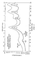
- FIGURE 2 illustrates attenuation level at different frequencies.
- FIGURE 2 illustrates examples of relative attenuation levels of temperatures due to natural phenomena present in the atmosphere.
- Attenuation plot 30 shows relative attenuation that may occur over a range of frequencies at sea level.
- Attenuation plot 32 shows relative attenuation that may occur over a range of frequencies at approximately 9150 meters of altitude.
- Attenuation plots 30 and 32 illustrate that certain frequency ranges experience relatively less attenuation than other frequencies ranges.
- the frequency ranges are generally centered around 35 Giga-Hertz, 94 Giga-Hertz, 140 Giga-Hertz, and 240 Giga-Hertz.
- thermal radiation signals 22 at and around these frequencies may experience relatively less attenuation than thermal radiation signals 22 at other frequencies.
- cold noise source 12 may generate thermal radiation signal 22 at approximately 35 Giga-Hertz, 94 Giga-Hertz, 140 Giga-Hertz, or 240 Giga-Hertz.
- the 240 Giga-Hertz frequency range may provide relatively good spatial resolution for a particular size of antenna. The atmospheric attenuation is higher at 240 Giga-Hertz than at the lower frequencies, but the higher spatial resolution may achieve relatively good signal-to-noise ratio in good weather with a range of greater than 100, 500, or 1000 feet, which may offset the higher attenuation.
- Antennas 14 and 18 may have any suitable design that converts electrical signals into thermal radiation signal 22, and vice-versa. Examples of suitable types of antennas may include horn antennas, spiral antennas, and parabolic antennas. Antennas 14 and 18 may be remotely configured.
- Detector 20 extracts the information signal from thermal radiation signal 22 received by radiometer receiver 16.
- the information signal may be demodulated from thermal radiation signal 22, or the information signal may be an intrusion detection signal that is generated in response to loss of thermal radiation signal 22 by radiometer receiver 16.
- Certain embodiments of system 10 may use a transmission medium that simulates a thermal body. This medium may be relatively difficult to detect apart from other thermal bodies. Thus, unwanted interception of thermal radiation signal 22 may be reduced.
- FIGURE 3 illustrates parameters involved in transmitting thermal radiation signal 22 from cold noise source 12 to radiometer receiver 16.
- the radiometer output temperature T Rec may be given by the formula: T Rec ⁇ E ML ⁇ A A A B • T C + A B - A A A B • T B ⁇ t p where:
- a carrier frequency is 94 Giga-Hertz
- antennas 14 and 16 have 8-inch diameters
- the range separation is 500 feet
- the main lobe efficiency is 97 percent (2.5 X 3 decibel (dB) beamwidth)
- the cold noise source temperature Tc ranges from 100 degrees Kelvin to 300 degrees Kelvin.
- the corresponding T Rec for the two temperatures are 299.8 degrees Kelvin and 300 degrees Kelvin or a received temperature change of 0.2 degrees Kelvin.
- radiometer receiver 16 has a noise figure of 4 decibels (dB), a bandwidth of 5 Giga-Hertz, and integration time of 0.1 seconds
- the receiver sensitivity or minimum detectable temperature difference is 0.033 degrees Kelvin.
- formula (2) provides one mathematical model for approximating the receiver output temperature T Rec seen by radiometer receiver 16
- equations for modeling the receiver output temperature T Rec may be used to approximate the performance of system 10.
- FIGURE 4 illustrates an example of the operating characteristics of system 10.
- the graph includes a drain voltage plot 34 and a detected voltage plot 36.
- Drain voltage plot 34 shows the voltage level applied to a drain terminal of a particular field-effect-transistor configured as cold noise source 12, and is directly proportional to the output power of cold noise source 12. Drain voltage plot 34 indicates that the output power of cold noise source 12 is relatively constant.
- Detected voltage plot 36 represents the thermal radiation signal 22 detected at detector 22.
- Detected voltage plot 36 has a number of regions 38 that fluctuate between -19.0 to - 23.5 volts. These fluctuations are due to interruptions in thermal radiation signal 22 that occur between transmitting antenna 14 and receiving antenna 18. In this particular example, the interruptions are caused by a generally opaque object that is placed between transmitting antenna 14 and receiving antenna 18.
- FIGURE 5 illustrates another embodiment of a system 110.
- system 110 is implemented as an intrusion detection system.
- System 110 includes a cold noise source 112 coupled to a pair of transmitting antennas 114, a radiometer receiver 116 coupled to a pair of receiving antennas 118 and a detector 120, and a reflector 124.
- Cold noise source 112 generates thermal radiation signals 122.
- Thermal radiation signals 122 encompass an item, which in this embodiment is an aircraft 126. A disruption of thermal radiation signals 122 by an intruder triggers an alarm.
- Detector 120 may detect disruptions in thermal radiation signals 122 and trigger an intrusion alarm. Any opaque object placed between a transmitting antenna 114 and its associated receiving antenna 118 may disrupt thermal radiation signal 122 and trigger an intrusion alarm. For example, an unauthorized person may disrupt a thermal radiation signal 122 by moving in between a transmitting antenna 114 and its associated receiving antenna 118.
- reflector 124 may reflect thermal radiation signal 122 along an angle.
- Reflector 124 may comprise an electrically conductive material.
- Reflector 124 may be oriented to reflect thermal radiation signal 122 from one transmitting antenna 114 to its associated receiving antenna 118.
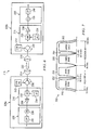
- FIGURE 6 illustrates another embodiment of a system 210 comprising a duplex communication link.
- System 210 has two nodes 228a and 228b that communicate with each other through corresponding antennas 214 and 218.
- System 210 may simultaneously transmit and receive thermal radiation signals 222 to and from either node 228.
- Cold noise source 212 may modulate thermal radiation signal 222 in any suitable manner to encode the information signal in thermal radiation signal 222.
- thermal radiation signal 222 is modulated by varying the thermal temperature of thermal radiation signal 222 to superimpose the information signal onto thermal radiation signal 222.
- thermal radiation signal 222 may be modulated by deviating the brightness temperature of the carrier signal.
- thermal radiation signal 222 may be modulated by pulse modulating thermal radiation signal 222.
- Each node 228a and 228b has a cold noise source 212, a radiometer receiver 216, a waveguide circulator 230, and a detector 220 coupled as shown.
- Cold noise source 212 and radiometer receiver 216 are coupled to its respective antenna 214 or 218 through waveguide circulator 230.
- waveguide circulator 230 is a low loss radio-frequency (RF) ferrite switch.
- radiometer receiver 216 comprises a super-heterodyne receiver that includes a mixer 232, a local oscillator 234, and an amplifier 236 coupled as shown.
- Mixer 232 mixes received thermal radiation signal 222 with a signal generated by local oscillator 234 to form an intermediate signal that is amplified by amplifier 236.
- radiometer receiver 218 comprises a super-heterodyne receiver
- radiometer receiver 218 may comprise any suitable type of receiver, such as a super-regenerative receiver, a tuned radio frequency receiver, or a direct detection receiver.
- Detector 220 receives the output of radiometer receiver 216.
- detector 220 has a demodulator 238 and a low-pass filter 240 coupled as shown.
- Demodulator 238 extracts the information signal from thermal radiation signal 222.
- demodulator 238 is a voltage identification digital (VID) demodulator that produces a voltage according to a received digital signal carried by thermal radiation signal 222.
- VID voltage identification digital
- FIGURE 7 illustrates one example of a spectral frequency pattern 250 that may be generated by system 210.
- cold noise source 212 of one node 228a may have a carrier frequency 252 of 92.5 Giga-Hertz
- cold noise source 212 of node 228b may have a carrier frequency 254 of 97.5 Giga-Hertz.
- Mixer 232 of node 228a mixes local oscillator 234 with received thermal radiation signal 222 to yield a lower side lobe 256 and an upper side lobe 258.
- Mixer 232 of node 228b mixes local oscillator 234 with received thermal radiation signal 222 to yield a lower side lobe 260 and an upper side lobe 262.
- FIGURE 8 illustrates an example of operating characteristics of system 210.
- the graph includes a drain voltage plot 270 and a detected voltage plot 272.
- Drain voltage plot 270 indicates the relative output power of thermal radiation signal 222 generated by cold noise source 212.
- thermal radiation signal 222 is modulated by a square-wave signal that simulates an effective radiated temperature variation of 135 degrees Kelvin to 300 degrees Kelvin.
- the modulation encodes the, information signal in thermal radiation signal 222.
- Detected voltage plot 272 indicates the thermal radiation signal 222 detected by detector 220.
- Detected voltage plot 272 generally follows drain voltage plot 270. Accordingly, the information signal was substantially preserved throughout transmission.
- system 10, 110, or 210 may be integrated or separated.
- detector 20, 120, or 220 may be coupled to radiometer receiver 16, 116, or 216 or may form a portion of radiometer receiver 16, 116, or 216.
- the operations of system 10, 110, or 210 may be performed by more, fewer, or other components.
- each node 228 of system 210 may include a waveguide circulator 230 for coupling cold noise source 212 and radiometer receiver 216 to its respective antenna 214 or 218, or a waveguide circulator 230 may not be needed if cold noise source 212 and radiometer receiver 216 have their own dedicated antenna.
- each refers to each member of a set or each member of a subset of a set.
- FIGURE 9 illustrates one embodiment of a series of steps that may be performed by system 10, 110, or 210.
- step 300 the method is initiated.
- cold noise source 12, 112, or 212 generates thermal radiation signal 22, 122, or 222 using transmitting antenna 14, 114, or 214.
- thermal radiation signal 22 or 122 may have a constant amplitude and frequency.
- thermal radiation signal 222 may be modulated with the information signal using amplitude modulation or pulse modulation.
- radiometer receiver 16, 116, or 216 receives thermal radiation signal 22, 122, or 222 and transmits thermal radiation signal 22, 122, or 222 through antenna 18, 118, or 218.
- Radiometer receiver 16, 116, or 216 may receive thermal radiation signal 22, 122, or 222 that progresses along any line-of-sight path.
- thermal radiation signal is reflected along a line-of-sight path using reflector 124.
- step 306 detector 20, 120, or 220 extracts the information signal from thermal radiation signal 22, 122, or 222.
- detector 122 generates an intrusion detection signal due to a momentary loss of thermal radiation signal 122.
- detector 220 demodulates the information signal from the thermal radiation signal 222.
- thermal radiation signal 222 may be modulated to encode the information signal in any suitable manner, such as by modulating the simulated temperature of cold noise source 212 or by modulating the amplitude of thermal radiation signal 222.
Landscapes
- Engineering & Computer Science (AREA)
- Radar, Positioning & Navigation (AREA)
- Remote Sensing (AREA)
- Computer Networks & Wireless Communication (AREA)
- Signal Processing (AREA)
- Physics & Mathematics (AREA)
- General Physics & Mathematics (AREA)
- Radiation Pyrometers (AREA)
- Geophysics And Detection Of Objects (AREA)
- Photometry And Measurement Of Optical Pulse Characteristics (AREA)
Claims (14)
- System (10, 110, 210), aufweisend:eine erste kalte Geräuschquelle (12, 112, 212), die dafür ausgelegt ist,ein erstes Thermostrahlungssignal (22, 122, 222) zu erzeugen, das elektromagnetische Strahlung, die von einem kalten thermischen Körper emittiert wird, simuliert und ein erstes Trägerfrequenzband aufweist, wobei das erste Thermostrahlungssignal (22, 122, 222) ein erstes Informationssignal trägt; unddas erste Thermostrahlungssignal über eine erste Antenne (14, 114, 214) zu senden;einen ersten Radiometerempfänger (16, 116, 216), der dafür ausgelegt ist,das erste Thermostrahlungssignal über eine zweite Antenne (18, 118, 218) zu empfangen; undeinen ersten Detektor (20, 120, 220), der mit dem ersten Radiometerempfänger (16, 116, 216) gekoppelt ist, wobei der erste Detektor (20, 120, 220) dafür ausgelegt ist,das erste Informationssignal aus dem ersten Thermostrahlungssignal (22, 122, 222) zu extrahieren.
- System (10, 110, 210) nach Anspruch 1, ferner einen Modulator aufweisend, der mit der ersten kalten Geräuschquelle (12, 112, 212) gekoppelt ist, wobei der Modulator dafür ausgelegt ist,
das erste Thermostrahlungssignal (22, 122, 222) zu modulieren, um das erste Informationssignal im ersten Thermostrahlungssignal (12, 112, 212) zu kodieren. - System (110) nach Anspruch 1 oder 2, wobei der erste Detektor (120) dafür ausgelegt ist, das erste Informationssignal aus dem ersten Thermostrahlungssignal (122) zu extrahieren, durch:Demodulieren des Thermostrahlungssignals (122), um das erste Informationssignal aus dem Thermostrahlungssignal (122) zu extrahieren; und/oderSystem, bei dem der erste Detektor (120) dafür ausgelegt ist,eine Pause im ersten Thermosignal (122) zu erfassen; undein Störungserfassungssignal als Reaktion auf die Erfassung zu erzeugen.
- System (10, 110, 210) nach einem der vorangehenden Ansprüche, wobei das erste Informationssignal ausgewählt ist aus der Gruppe bestehend aus einem amplitudenmodulierten Signal und einem pulsmodulierten Signal.
- System (210) nach einem der vorangehenden Ansprüche, ferner aufweisend:eine zweite kalte Geräuschquelle (212), die dafür ausgelegt ist,ein zweites Thermostrahlungssignal (22, 122, 222) zu erzeugen, das elektromagnetische Strahlung, die von einem kalten thermischen Körper emittiert wird, simuliert und ein zweites Trägerfrequenzband aufweist, wobei das zweite Trägerfrequenzband von dem ersten Trägerfrequenzband verschieden ist, und wobei das zweite Thermostrahlungssignal ein zweites Informationssignal trägt; unddas zweite Thermostrahlungssignal über die zweite Antenne (218) zu senden;einen zweiten Radiometerempfänger (216), der dafür ausgelegt ist,das zweite Thermostrahlungssignal über die erste Antenne (214) zu empfangen; undeinen zweiten Detektor (220), der mit dem zweiten Radiometerempfänger (216) gekoppelt ist, wobei der zweite Detektor (220) dafür ausgelegt ist,das zweite Informationssignal aus dem zweiten Thermostrahlungssignal zu extrahieren.
- System (10, 110, 210) nach einem der vorangehenden Ansprüche, wobei die erste Antenne (14, 114, 214) oder die zweite Antenne (18, 118, 218) ausgewählt ist aus der Gruppe, die aus einer Hornantenne, einer Spiralantenne und einer Parabolantenne besteht.
- System (110) nach einem der vorangehenden Ansprüche, ferner aufweisend:einen Reflektor (124), der zwischen der ersten Antenne (114) und der zweiten Antenne (118) angeordnet ist, wobei der Reflektor (124) so ausgelegt ist, dass er das erste Thermostrahlungssignal reflektiert.
- Verfahren, umfassend:Erzeugen eines ersten Thermostrahlungssignals (22, 122, 222), das elektromagnetische Strahlung, die von einem kalten thermischen Körper emittiert wird, simuliert und ein erstes Trägerfrequenzband aufweist, durch eine erste kalte Geräuschquelle (12, 112, 212), wobei das erste Thermostrahlungssignal (22, 122, 222) ein erstes Informationssignal trägt;Senden des ersten Thermostrahlungssignals (22, 122, 222) über eine erste Antenne (14, 114, 214);Empfangen des ersten Thermostrahlungssignals an einem ersten Radiometerempfänger (16, 116, 216) über eine zweite Antenne (18, 118, 218); undExtrahieren des ersten Informationssignals aus dem ersten Thermostrahlungssignal (22, 122, 222) durch einen ersten Detektor (20, 120, 220), der mit dem ersten Radiometerempfänger (16, 116, 216) gekoppelt ist.
- Verfahren nach Anspruch 8, ferner umfassend:Modulieren des ersten Thermostrahlungssignals (22, 122, 222) durch einen Modulator, der mit der ersten kalten Geräuschquelle (12, 112, 212) gekoppelt ist, um das erste Informationssignal im ersten Thermostrahlungssignal (22, 122, 222) zu kodieren.
- Verfahren nach Anspruch 8 oder 9, wobei das Extrahieren des ersten Informationssignals aus dem ersten Thermostrahlungssignal (22, 122, 222) ferner umfasst:Demodulieren des Thermostrahlungssignals (22, 122, 222), um das erste Informationssignal aus dem Thermostrahlungssignal (22, 122, 222) zu extrahieren, und/oderVerfahren, in dem das erste Informationssignal ausgewählt wird aus der Gruppe bestehend aus einem amplitudenmodulierten Signal und einem pulsmodulierten Signal.
- Verfahren nach einem der Ansprüche 8 bis 10, ferner umfassend:Erfassen einer Pause im ersten Thermostrahlungssignal; undErzeugen eines Störungserfassungssignals als Reaktion auf die Erfassung.
- Verfahren nach einem der Ansprüche 8 bis 11, ferner umfassend:Erzeugen eines zweiten Thermostrahlungssignals (222), das elektromagnetische Strahlung simuliert, die von einem kalten thermischen Körper emittiert wird und ein zweites Trägerfrequenzband aufweist, durch eine zweite kalte Geräuschquelle (212), wobei das zweite Trägerfrequenzband vom ersten Trägerfrequenzband verschieden ist, wobei das zweite Thermostrahlungssignal (222) ein zweites Informationssignal trägt;Senden des zweiten Thermostrahlungssignals (222) über die zweite Antenne (218);Empfangen des zweiten Thermostrahlungssignals (222) an einem zweiten Radiometerempfänger (216) über die erste Antenne (214); undExtrahieren des zweiten Informationssignals aus dem zweiten Thermostrahlungssignal (222) durch einen zweiten Detektor (220), der mit dem zweiten Radiometerempfänger (216) gekoppelt ist.
- Verfahren nach einem der Ansprüche 8 bis 10, wobei die erste Antenne (14, 114, 214) oder die zweite Antenne (18, 118, 218) ausgewählt ist aus der Gruppe bestehend aus einer Hornantenne, einer Spiralantenne und einer Parabolantenne.
- Verfahren nach einem der Ansprüche 8 bis 13, ferner umfassend:Reflektieren des ersten Thermostrahlungssignals (122) unter Verwendung eines Reflektors (124), der zwischen der ersten Antenne (114) und der zweiten Antenne (118) angeordnet ist.
Applications Claiming Priority (2)
| Application Number | Priority Date | Filing Date | Title |
|---|---|---|---|
| US86774606P | 2006-11-29 | 2006-11-29 | |
| PCT/US2007/085935 WO2008067466A1 (en) | 2006-11-29 | 2007-11-29 | Cold noise source system |
Publications (2)
| Publication Number | Publication Date |
|---|---|
| EP2087597A1 EP2087597A1 (de) | 2009-08-12 |
| EP2087597B1 true EP2087597B1 (de) | 2014-02-26 |
Family
ID=39272382
Family Applications (1)
| Application Number | Title | Priority Date | Filing Date |
|---|---|---|---|
| EP07854826.0A Not-in-force EP2087597B1 (de) | 2006-11-29 | 2007-11-29 | Kaltrauschquellensystem |
Country Status (4)
| Country | Link |
|---|---|
| US (1) | US8330600B2 (de) |
| EP (1) | EP2087597B1 (de) |
| JP (1) | JP2010511178A (de) |
| WO (1) | WO2008067466A1 (de) |
Families Citing this family (9)
| Publication number | Priority date | Publication date | Assignee | Title |
|---|---|---|---|---|
| KR100996708B1 (ko) * | 2008-08-13 | 2010-11-25 | 한국전자통신연구원 | 태양을 이용한 안테나 이득 측정 장치 및 방법 |
| RU2400768C1 (ru) * | 2009-01-19 | 2010-09-27 | Открытое акционерное общество "Научно-исследовательский институт измерительных приборов" (ОАО "НИИИП") | Способ радиолокационного обзора зоны пространства |
| RU2403585C2 (ru) * | 2009-02-02 | 2010-11-10 | Открытое акционерное общество "Научно-исследовательский институт измерительных приборов" (ОАО "НИИИП") | Способ обнаружения сигналов в системах цифровой обработки (варианты) |
| RU2409821C2 (ru) * | 2009-04-14 | 2011-01-20 | Открытое акционерное общество "Научно-исследовательский институт измерительных приборов" (ОАО "НИИИП") | Обнаружитель радиолокационных сигналов |
| RU2408028C1 (ru) * | 2009-05-04 | 2010-12-27 | Открытое акционерное общество "Научно-исследовательский институт измерительных приборов" (ОАО "НИИИП") | Способ обзора зоны радиолокационной станции |
| US8485722B1 (en) | 2009-10-14 | 2013-07-16 | Raytheon Company | Subsurface temperature measurement system |
| US9077412B2 (en) * | 2010-09-10 | 2015-07-07 | The Regents Of The University Of California | Regenerative receiver architectures for millimeter-wave and sub-millimeter-wave imaging and communication |
| RU2508559C2 (ru) * | 2012-04-24 | 2014-02-27 | Открытое акционерное общество "НИИ измерительных приборов - Новосибирский завод имени Коминтерна" (ОАО "НПО НИИИП-НЗиК") | Способ обзора пространства радиолокационной станцией |
| RU2518052C2 (ru) * | 2012-09-18 | 2014-06-10 | ОТКРЫТОЕ АКЦИОНЕРНОЕ ОБЩЕСТВО "НИИ измерительных приборов-Новосибирский завод имени Коминтера" /ОАО "НПО НИИИП-НЗиК"/ | Способ стабилизации вероятности ложной тревоги (варианты) и устройство для его реализации (варианты) |
Family Cites Families (9)
| Publication number | Priority date | Publication date | Assignee | Title |
|---|---|---|---|---|
| JPS62269029A (ja) * | 1986-05-19 | 1987-11-21 | Daido Steel Co Ltd | 物体の温度を測定する方法および装置 |
| US5990822A (en) * | 1989-04-14 | 1999-11-23 | Honigsbaum; Richard F. | Process and apparatus for finding stealthcraft |
| US6225955B1 (en) * | 1995-06-30 | 2001-05-01 | The United States Of America As Represented By The Secretary Of The Army | Dual-mode, common-aperture antenna system |
| US6137440A (en) * | 1996-12-03 | 2000-10-24 | Raytheon Company | Microwave active solid state cold/warm noise source |
| EP0944952B1 (de) * | 1996-12-03 | 2009-01-07 | Raytheon Company | Variable mikrowellen kalter oder heisser rauschquelle |
| JP2943753B2 (ja) * | 1997-02-05 | 1999-08-30 | 日本電気株式会社 | 防犯機能付き無線通信装置 |
| US6834991B2 (en) * | 2002-09-23 | 2004-12-28 | Raytheon Company | Radiometer with programmable noise source calibration |
| JPWO2005045473A1 (ja) * | 2003-11-10 | 2007-05-17 | オムロン株式会社 | 処理装置および対象物検出装置 |
| US20070115762A1 (en) * | 2005-11-21 | 2007-05-24 | Wisnudel Marc B | Optical article having anti-theft feature and a system and method for inhibiting theft of same |
-
2007
- 2007-11-29 EP EP07854826.0A patent/EP2087597B1/de not_active Not-in-force
- 2007-11-29 JP JP2009539486A patent/JP2010511178A/ja active Pending
- 2007-11-29 US US11/947,650 patent/US8330600B2/en active Active
- 2007-11-29 WO PCT/US2007/085935 patent/WO2008067466A1/en not_active Ceased
Also Published As
| Publication number | Publication date |
|---|---|
| US8330600B2 (en) | 2012-12-11 |
| WO2008067466A1 (en) | 2008-06-05 |
| US20080246669A1 (en) | 2008-10-09 |
| JP2010511178A (ja) | 2010-04-08 |
| EP2087597A1 (de) | 2009-08-12 |
Similar Documents
| Publication | Publication Date | Title |
|---|---|---|
| US8330600B2 (en) | Cold noise source system | |
| El-Absi et al. | High-accuracy indoor localization based on chipless RFID systems at THz band | |
| Rey et al. | Channel sounding techniques for applications in THz communications: A first correlation based channel sounder for ultra-wideband dynamic channel measurements at 300 GHz | |
| Han et al. | Joint wireless communication and radar sensing systems–state of the art and future prospects | |
| Papazian et al. | A radio channel sounder for mobile millimeter-wave communications: System implementation and measurement assessment | |
| Mishra et al. | FOPEN capabilities of commensal radars based on whitespace communication systems | |
| Guidi et al. | Millimeter-wave beamsteering for passive RFID tag localization | |
| Wang et al. | AllSpark: Enabling long-range backscatter for vehicle-to-infrastructure communication | |
| Hilton et al. | Narrowband passive RF tags for frequency-selective harmonic Doppler radar tracking | |
| GB2165413A (en) | Generating artificial target marks in an SAR display | |
| Hanif et al. | WiSpy: Through-wall movement sensing and person counting using commodity WiFi signals | |
| Alam et al. | A mathematical framework, simulation, and measurement of harmonic identification systems | |
| Jiang et al. | Terahertz-empowered communications and sensing in 6G systems: Opportunities and challenges | |
| Owfi et al. | Autoencoder-based radio frequency interference mitigation for SMAP passive radiometer | |
| Guidi et al. | Passive millimeter-wave RFID using backscattered signals | |
| Song et al. | Communication jamming of high power microwave pulse to UAV | |
| Futatsumori et al. | Detection characteristic evaluations of optically-connected wideband 96 GHz millimeter-wave radar for airport surface foreign object debris detection | |
| Davis et al. | Waveform diversity for ultra‐wide band surveillance radars | |
| Sanz et al. | Automatic indoor-outdoor detection using signals of opportunity | |
| Yarovoy | Ultra-wideband systems | |
| Mazzaro | Detection of radio-frequency electronics by stimulated emission of carrier modulation | |
| Siddiqui et al. | Ambient backscattering transponder with independently switchable Rx and Tx antennas | |
| Ecola et al. | Sarlink: Satellite backscatter connectivity using synthetic aperture radar | |
| Khaliel et al. | Evaluation and comparison of planar printable and grounded harmonic rfid tags | |
| Saleem et al. | Design and analysis of a 25 GHz frequency modulated continuous wave radar for foreign object debris detection |
Legal Events
| Date | Code | Title | Description |
|---|---|---|---|
| PUAI | Public reference made under article 153(3) epc to a published international application that has entered the european phase |
Free format text: ORIGINAL CODE: 0009012 |
|
| 17P | Request for examination filed |
Effective date: 20090507 |
|
| AK | Designated contracting states |
Kind code of ref document: A1 Designated state(s): AT BE BG CH CY CZ DE DK EE ES FI FR GB GR HU IE IS IT LI LT LU LV MC MT NL PL PT RO SE SI SK TR |
|
| DAX | Request for extension of the european patent (deleted) | ||
| 17Q | First examination report despatched |
Effective date: 20130523 |
|
| GRAP | Despatch of communication of intention to grant a patent |
Free format text: ORIGINAL CODE: EPIDOSNIGR1 |
|
| INTG | Intention to grant announced |
Effective date: 20130930 |
|
| GRAS | Grant fee paid |
Free format text: ORIGINAL CODE: EPIDOSNIGR3 |
|
| GRAA | (expected) grant |
Free format text: ORIGINAL CODE: 0009210 |
|
| AK | Designated contracting states |
Kind code of ref document: B1 Designated state(s): AT BE BG CH CY CZ DE DK EE ES FI FR GB GR HU IE IS IT LI LT LU LV MC MT NL PL PT RO SE SI SK TR |
|
| REG | Reference to a national code |
Ref country code: GB Ref legal event code: FG4D |
|
| REG | Reference to a national code |
Ref country code: CH Ref legal event code: EP |
|
| REG | Reference to a national code |
Ref country code: AT Ref legal event code: REF Ref document number: 654099 Country of ref document: AT Kind code of ref document: T Effective date: 20140315 |
|
| REG | Reference to a national code |
Ref country code: IE Ref legal event code: FG4D |
|
| REG | Reference to a national code |
Ref country code: DE Ref legal event code: R096 Ref document number: 602007035281 Country of ref document: DE Effective date: 20140410 |
|
| REG | Reference to a national code |
Ref country code: NL Ref legal event code: VDEP Effective date: 20140226 |
|
| REG | Reference to a national code |
Ref country code: AT Ref legal event code: MK05 Ref document number: 654099 Country of ref document: AT Kind code of ref document: T Effective date: 20140226 |
|
| REG | Reference to a national code |
Ref country code: LT Ref legal event code: MG4D |
|
| PG25 | Lapsed in a contracting state [announced via postgrant information from national office to epo] |
Ref country code: IS Free format text: LAPSE BECAUSE OF FAILURE TO SUBMIT A TRANSLATION OF THE DESCRIPTION OR TO PAY THE FEE WITHIN THE PRESCRIBED TIME-LIMIT Effective date: 20140626 Ref country code: LT Free format text: LAPSE BECAUSE OF FAILURE TO SUBMIT A TRANSLATION OF THE DESCRIPTION OR TO PAY THE FEE WITHIN THE PRESCRIBED TIME-LIMIT Effective date: 20140226 |
|
| PG25 | Lapsed in a contracting state [announced via postgrant information from national office to epo] |
Ref country code: AT Free format text: LAPSE BECAUSE OF FAILURE TO SUBMIT A TRANSLATION OF THE DESCRIPTION OR TO PAY THE FEE WITHIN THE PRESCRIBED TIME-LIMIT Effective date: 20140226 Ref country code: NL Free format text: LAPSE BECAUSE OF FAILURE TO SUBMIT A TRANSLATION OF THE DESCRIPTION OR TO PAY THE FEE WITHIN THE PRESCRIBED TIME-LIMIT Effective date: 20140226 Ref country code: FI Free format text: LAPSE BECAUSE OF FAILURE TO SUBMIT A TRANSLATION OF THE DESCRIPTION OR TO PAY THE FEE WITHIN THE PRESCRIBED TIME-LIMIT Effective date: 20140226 Ref country code: PT Free format text: LAPSE BECAUSE OF FAILURE TO SUBMIT A TRANSLATION OF THE DESCRIPTION OR TO PAY THE FEE WITHIN THE PRESCRIBED TIME-LIMIT Effective date: 20140626 Ref country code: SE Free format text: LAPSE BECAUSE OF FAILURE TO SUBMIT A TRANSLATION OF THE DESCRIPTION OR TO PAY THE FEE WITHIN THE PRESCRIBED TIME-LIMIT Effective date: 20140226 Ref country code: CY Free format text: LAPSE BECAUSE OF FAILURE TO SUBMIT A TRANSLATION OF THE DESCRIPTION OR TO PAY THE FEE WITHIN THE PRESCRIBED TIME-LIMIT Effective date: 20140226 |
|
| PG25 | Lapsed in a contracting state [announced via postgrant information from national office to epo] |
Ref country code: BE Free format text: LAPSE BECAUSE OF FAILURE TO SUBMIT A TRANSLATION OF THE DESCRIPTION OR TO PAY THE FEE WITHIN THE PRESCRIBED TIME-LIMIT Effective date: 20140226 Ref country code: LV Free format text: LAPSE BECAUSE OF FAILURE TO SUBMIT A TRANSLATION OF THE DESCRIPTION OR TO PAY THE FEE WITHIN THE PRESCRIBED TIME-LIMIT Effective date: 20140226 |
|
| PG25 | Lapsed in a contracting state [announced via postgrant information from national office to epo] |
Ref country code: EE Free format text: LAPSE BECAUSE OF FAILURE TO SUBMIT A TRANSLATION OF THE DESCRIPTION OR TO PAY THE FEE WITHIN THE PRESCRIBED TIME-LIMIT Effective date: 20140226 Ref country code: RO Free format text: LAPSE BECAUSE OF FAILURE TO SUBMIT A TRANSLATION OF THE DESCRIPTION OR TO PAY THE FEE WITHIN THE PRESCRIBED TIME-LIMIT Effective date: 20140226 Ref country code: CZ Free format text: LAPSE BECAUSE OF FAILURE TO SUBMIT A TRANSLATION OF THE DESCRIPTION OR TO PAY THE FEE WITHIN THE PRESCRIBED TIME-LIMIT Effective date: 20140226 Ref country code: DK Free format text: LAPSE BECAUSE OF FAILURE TO SUBMIT A TRANSLATION OF THE DESCRIPTION OR TO PAY THE FEE WITHIN THE PRESCRIBED TIME-LIMIT Effective date: 20140226 |
|
| REG | Reference to a national code |
Ref country code: DE Ref legal event code: R097 Ref document number: 602007035281 Country of ref document: DE |
|
| PG25 | Lapsed in a contracting state [announced via postgrant information from national office to epo] |
Ref country code: SK Free format text: LAPSE BECAUSE OF FAILURE TO SUBMIT A TRANSLATION OF THE DESCRIPTION OR TO PAY THE FEE WITHIN THE PRESCRIBED TIME-LIMIT Effective date: 20140226 Ref country code: ES Free format text: LAPSE BECAUSE OF FAILURE TO SUBMIT A TRANSLATION OF THE DESCRIPTION OR TO PAY THE FEE WITHIN THE PRESCRIBED TIME-LIMIT Effective date: 20140226 Ref country code: PL Free format text: LAPSE BECAUSE OF FAILURE TO SUBMIT A TRANSLATION OF THE DESCRIPTION OR TO PAY THE FEE WITHIN THE PRESCRIBED TIME-LIMIT Effective date: 20140226 |
|
| PLBE | No opposition filed within time limit |
Free format text: ORIGINAL CODE: 0009261 |
|
| STAA | Information on the status of an ep patent application or granted ep patent |
Free format text: STATUS: NO OPPOSITION FILED WITHIN TIME LIMIT |
|
| 26N | No opposition filed |
Effective date: 20141127 |
|
| REG | Reference to a national code |
Ref country code: DE Ref legal event code: R097 Ref document number: 602007035281 Country of ref document: DE Effective date: 20141127 |
|
| PG25 | Lapsed in a contracting state [announced via postgrant information from national office to epo] |
Ref country code: SI Free format text: LAPSE BECAUSE OF FAILURE TO SUBMIT A TRANSLATION OF THE DESCRIPTION OR TO PAY THE FEE WITHIN THE PRESCRIBED TIME-LIMIT Effective date: 20140226 |
|
| PG25 | Lapsed in a contracting state [announced via postgrant information from national office to epo] |
Ref country code: LU Free format text: LAPSE BECAUSE OF FAILURE TO SUBMIT A TRANSLATION OF THE DESCRIPTION OR TO PAY THE FEE WITHIN THE PRESCRIBED TIME-LIMIT Effective date: 20141129 Ref country code: MC Free format text: LAPSE BECAUSE OF FAILURE TO SUBMIT A TRANSLATION OF THE DESCRIPTION OR TO PAY THE FEE WITHIN THE PRESCRIBED TIME-LIMIT Effective date: 20140226 |
|
| REG | Reference to a national code |
Ref country code: CH Ref legal event code: PL |
|
| PG25 | Lapsed in a contracting state [announced via postgrant information from national office to epo] |
Ref country code: LI Free format text: LAPSE BECAUSE OF NON-PAYMENT OF DUE FEES Effective date: 20141130 Ref country code: CH Free format text: LAPSE BECAUSE OF NON-PAYMENT OF DUE FEES Effective date: 20141130 |
|
| REG | Reference to a national code |
Ref country code: IE Ref legal event code: MM4A |
|
| REG | Reference to a national code |
Ref country code: FR Ref legal event code: PLFP Year of fee payment: 9 |
|
| PG25 | Lapsed in a contracting state [announced via postgrant information from national office to epo] |
Ref country code: IE Free format text: LAPSE BECAUSE OF NON-PAYMENT OF DUE FEES Effective date: 20141129 |
|
| PG25 | Lapsed in a contracting state [announced via postgrant information from national office to epo] |
Ref country code: BG Free format text: LAPSE BECAUSE OF FAILURE TO SUBMIT A TRANSLATION OF THE DESCRIPTION OR TO PAY THE FEE WITHIN THE PRESCRIBED TIME-LIMIT Effective date: 20140226 |
|
| PG25 | Lapsed in a contracting state [announced via postgrant information from national office to epo] |
Ref country code: GR Free format text: LAPSE BECAUSE OF FAILURE TO SUBMIT A TRANSLATION OF THE DESCRIPTION OR TO PAY THE FEE WITHIN THE PRESCRIBED TIME-LIMIT Effective date: 20140527 |
|
| PG25 | Lapsed in a contracting state [announced via postgrant information from national office to epo] |
Ref country code: TR Free format text: LAPSE BECAUSE OF FAILURE TO SUBMIT A TRANSLATION OF THE DESCRIPTION OR TO PAY THE FEE WITHIN THE PRESCRIBED TIME-LIMIT Effective date: 20140226 Ref country code: HU Free format text: LAPSE BECAUSE OF FAILURE TO SUBMIT A TRANSLATION OF THE DESCRIPTION OR TO PAY THE FEE WITHIN THE PRESCRIBED TIME-LIMIT; INVALID AB INITIO Effective date: 20071129 Ref country code: MT Free format text: LAPSE BECAUSE OF FAILURE TO SUBMIT A TRANSLATION OF THE DESCRIPTION OR TO PAY THE FEE WITHIN THE PRESCRIBED TIME-LIMIT Effective date: 20140226 |
|
| REG | Reference to a national code |
Ref country code: FR Ref legal event code: PLFP Year of fee payment: 10 |
|
| REG | Reference to a national code |
Ref country code: FR Ref legal event code: PLFP Year of fee payment: 11 |
|
| REG | Reference to a national code |
Ref country code: FR Ref legal event code: PLFP Year of fee payment: 12 |
|
| PGFP | Annual fee paid to national office [announced via postgrant information from national office to epo] |
Ref country code: DE Payment date: 20181113 Year of fee payment: 12 |
|
| PGFP | Annual fee paid to national office [announced via postgrant information from national office to epo] |
Ref country code: GB Payment date: 20181128 Year of fee payment: 12 Ref country code: IT Payment date: 20181122 Year of fee payment: 12 Ref country code: FR Payment date: 20181011 Year of fee payment: 12 |
|
| REG | Reference to a national code |
Ref country code: DE Ref legal event code: R119 Ref document number: 602007035281 Country of ref document: DE |
|
| GBPC | Gb: european patent ceased through non-payment of renewal fee |
Effective date: 20191129 |
|
| PG25 | Lapsed in a contracting state [announced via postgrant information from national office to epo] |
Ref country code: GB Free format text: LAPSE BECAUSE OF NON-PAYMENT OF DUE FEES Effective date: 20191129 Ref country code: DE Free format text: LAPSE BECAUSE OF NON-PAYMENT OF DUE FEES Effective date: 20200603 Ref country code: FR Free format text: LAPSE BECAUSE OF NON-PAYMENT OF DUE FEES Effective date: 20191130 Ref country code: IT Free format text: LAPSE BECAUSE OF NON-PAYMENT OF DUE FEES Effective date: 20191129 |