EP2086796B1 - Clip-on inner panel seal assembly - Google Patents
Clip-on inner panel seal assembly Download PDFInfo
- Publication number
- EP2086796B1 EP2086796B1 EP07864013A EP07864013A EP2086796B1 EP 2086796 B1 EP2086796 B1 EP 2086796B1 EP 07864013 A EP07864013 A EP 07864013A EP 07864013 A EP07864013 A EP 07864013A EP 2086796 B1 EP2086796 B1 EP 2086796B1
- Authority
- EP
- European Patent Office
- Prior art keywords
- seal assembly
- finger
- planar portion
- opening
- vehicle
- Prior art date
- Legal status (The legal status is an assumption and is not a legal conclusion. Google has not performed a legal analysis and makes no representation as to the accuracy of the status listed.)
- Ceased
Links
- 239000004033 plastic Substances 0.000 claims description 7
- 239000000463 material Substances 0.000 claims description 4
- 229920006342 thermoplastic vulcanizate Polymers 0.000 claims description 3
- 238000003780 insertion Methods 0.000 claims description 2
- 230000037431 insertion Effects 0.000 claims description 2
- 238000000034 method Methods 0.000 description 4
- 229920002725 thermoplastic elastomer Polymers 0.000 description 4
- 238000009434 installation Methods 0.000 description 3
- 238000007789 sealing Methods 0.000 description 3
- 230000007704 transition Effects 0.000 description 3
- 238000004519 manufacturing process Methods 0.000 description 2
- 239000004677 Nylon Substances 0.000 description 1
- 239000004743 Polypropylene Substances 0.000 description 1
- 239000000853 adhesive Substances 0.000 description 1
- 230000001070 adhesive effect Effects 0.000 description 1
- 239000002390 adhesive tape Substances 0.000 description 1
- 230000015572 biosynthetic process Effects 0.000 description 1
- 238000000465 moulding Methods 0.000 description 1
- 229920001778 nylon Polymers 0.000 description 1
- 230000002093 peripheral effect Effects 0.000 description 1
- -1 polypropylene Polymers 0.000 description 1
- 229920001155 polypropylene Polymers 0.000 description 1
Images
Classifications
-
- B—PERFORMING OPERATIONS; TRANSPORTING
- B60—VEHICLES IN GENERAL
- B60J—WINDOWS, WINDSCREENS, NON-FIXED ROOFS, DOORS, OR SIMILAR DEVICES FOR VEHICLES; REMOVABLE EXTERNAL PROTECTIVE COVERINGS SPECIALLY ADAPTED FOR VEHICLES
- B60J10/00—Sealing arrangements
- B60J10/80—Sealing arrangements specially adapted for opening panels, e.g. doors
-
- B—PERFORMING OPERATIONS; TRANSPORTING
- B60—VEHICLES IN GENERAL
- B60J—WINDOWS, WINDSCREENS, NON-FIXED ROOFS, DOORS, OR SIMILAR DEVICES FOR VEHICLES; REMOVABLE EXTERNAL PROTECTIVE COVERINGS SPECIALLY ADAPTED FOR VEHICLES
- B60J10/00—Sealing arrangements
- B60J10/30—Sealing arrangements characterised by the fastening means
-
- B—PERFORMING OPERATIONS; TRANSPORTING
- B60—VEHICLES IN GENERAL
- B60J—WINDOWS, WINDSCREENS, NON-FIXED ROOFS, DOORS, OR SIMILAR DEVICES FOR VEHICLES; REMOVABLE EXTERNAL PROTECTIVE COVERINGS SPECIALLY ADAPTED FOR VEHICLES
- B60J10/00—Sealing arrangements
- B60J10/45—Assembling sealing arrangements with vehicle parts
-
- B—PERFORMING OPERATIONS; TRANSPORTING
- B60—VEHICLES IN GENERAL
- B60R—VEHICLES, VEHICLE FITTINGS, OR VEHICLE PARTS, NOT OTHERWISE PROVIDED FOR
- B60R13/00—Elements for body-finishing, identifying, or decorating; Arrangements or adaptations for advertising purposes
- B60R13/06—Sealing strips
-
- F—MECHANICAL ENGINEERING; LIGHTING; HEATING; WEAPONS; BLASTING
- F16—ENGINEERING ELEMENTS AND UNITS; GENERAL MEASURES FOR PRODUCING AND MAINTAINING EFFECTIVE FUNCTIONING OF MACHINES OR INSTALLATIONS; THERMAL INSULATION IN GENERAL
- F16B—DEVICES FOR FASTENING OR SECURING CONSTRUCTIONAL ELEMENTS OR MACHINE PARTS TOGETHER, e.g. NAILS, BOLTS, CIRCLIPS, CLAMPS, CLIPS OR WEDGES; JOINTS OR JOINTING
- F16B5/00—Joining sheets or plates, e.g. panels, to one another or to strips or bars parallel to them
- F16B5/12—Fastening strips or bars to sheets or plates, e.g. rubber strips, decorative strips for motor vehicles, by means of clips
-
- B—PERFORMING OPERATIONS; TRANSPORTING
- B60—VEHICLES IN GENERAL
- B60R—VEHICLES, VEHICLE FITTINGS, OR VEHICLE PARTS, NOT OTHERWISE PROVIDED FOR
- B60R11/00—Arrangements for holding or mounting articles, not otherwise provided for
- B60R2011/0042—Arrangements for holding or mounting articles, not otherwise provided for characterised by mounting means
- B60R2011/0049—Arrangements for holding or mounting articles, not otherwise provided for characterised by mounting means for non integrated articles
- B60R2011/005—Connection with the vehicle part
- B60R2011/0059—Connection with the vehicle part using clips, clamps, straps or the like
-
- B—PERFORMING OPERATIONS; TRANSPORTING
- B60—VEHICLES IN GENERAL
- B60Y—INDEXING SCHEME RELATING TO ASPECTS CROSS-CUTTING VEHICLE TECHNOLOGY
- B60Y2200/00—Type of vehicle
- B60Y2200/10—Road Vehicles
Definitions
- This application is directed to a weatherstrip or weatherseal, and particularly one that includes an integrated attachment arrangement.
- the subject new weatherstrip finds use in areas where little room is available to secure the weatherstrip and finds particular use in an automotive vehicle, for example, between or along closely spaced body panels.
- a weatherstrip or weatherseal As is known, selected areas of a vehicle require a weatherstrip or weatherseal. In particular instances, such as the A-pillar, B-pillar, C-pillar and rocker panel, there is little room to provide attachment of the weatherstrip to the vehicle. It is not uncommon to use a riveted attachment scheme such as shown in Figure 1 where welded-on studs or attachment pins are provided on an outer body panel adjacent its interface with an inner body panel. The studs or pins are used as a means to securely attach the weatherstrip to the vehicle since other known attachment arrangements cannot be effectively used. As will be appreciated, the weatherstrip requires corresponding openings or holes in a bracket carrying or joined to the weatherstrip in order to secure the weatherstrip to these pins.
- WO 2005/009767 A is regarded as closest prior art and discloses a vehicle seat assembly with integrated attachment feature for securing the seal to an associated vehicle having inner and outer panel, the inner panel having an opening, the vehicle seal comprising a thin-walled planar portion including a finger dimensioned for receipt by the opening and between the panels and a flexible seal.
- a vehicle seal assembly includes an integrated attachment feature for securing a seal to an associated vehicle having inner and outer panels joined along a flange region.
- the inner panel includes first and second spaced openings aligned in a direction extending from the flange region.
- the seal assembly includes a thin-walled portion dimensioned to overlie one of the panels and having a finger secured to one end for receipt through the associated first opening in a retaining member dimensioned for receipt though the associated second opening.
- a flexible seal extends outwardly from the planar portion of the assembly.
- the retaining member preferably extends outwardly from the planar portion in a direction substantially perpendicular to the planar portion.
- a finger includes first and second spaced finger portions that support the seal assembly.
- the retaining member includes a ramped leading edge for deflecting the retaining member over an edge of the body panel adjacent the associated first opening.
- a raised cover may be provided over the finger and retaining member.
- One benefit of the invention resides in the ability to mount the seal in tight areas.
- Another benefit of the invention resides in the reduced costs of manufacture and assembly.
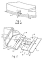
- FIGURE 1 is a prior art illustration of the prior art manner of attaching a seal assembly.
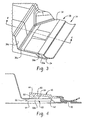
- FIGURE 2 is a perspective view of the seal assembly prior to installation.
- FIGURE 3 is a perspective view of the seal assembly shown in an installed condition adjacent the flange region joining inner and outer body panels.
- FIGURE 4 is a cross-sectional view taken generally along the lines 5-5 of FIGURE 2 .
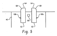
- FIGURE 5 is a plan view of the bottom or underside of the seal assembly.
- an inner body panel 20 is joined to an outer body panel 22, particularly along a flange region or area 24.
- the flange is a joined region at peripheral edges of the inner and outer body panels and is oftentimes a welded arrangement where one edge of one body panel (usually the outer body panel) is folded onto an edge of the other body panel (usually the inner body panel) and welded to secure the body panels together along the edge of a vehicle surface such as a rocker panel, A-pillar, B-pillar, C-pillar, etc. of an automotive vehicle. It is common that the inner and outer door panels are closely spaced to one another in a region spaced inwardly from the flange region.
- the inner panel is slightly offset and extends substantially parallel to the outer panel in a region adjacent and spaced inwardly from the flange region.
- a seal such as a weatherseal in these types of regions because there is little room for attaching the seal to one of the panels.
- FIGURE 1 it is common to employ studs or pins 26 that are welded to the inner panel adjacent the flange region.
- the pins 26 form one portion of the attachment assembly of an associated seal (not shown).
- a bracket is typically secured to the weatherseal and has openings formed therein for receipt over the pins 26.
- This attachment arrangement requires expensive equipment to secure the pins to the body panel, and also to provide the bracket in the seal assembly. Moreover, the tight area makes it difficult to remove the seal assembly once it has been installed.
- FIGURES 2 and 3 illustrate a weatherstrip or seal assembly 30 with integral fastener clips that finds particular use in these tight areas.
- the seal assembly 30 is comprised of two major portions, a rigid, mounting portion 32 and a softer, seal portion 34. It is preferable that the rigid and soft portions 32, 34 be formed of moldable materials, for example, a rigid plastic 32 and a soft TPE (thermoplastic elastomer) for seal portion 34.
- a two-shot molded process allows the rigid plastic to be introduced into a mold cavity in a first shot, and a soft TPE (thermoplastic elastomer) introduced into the mold cavity in a second shot. In this manner, the two dissimilar materials are fused along interfacing regions so that when fully set, a one-piece seal assembly 30 results.
- the inner body panel 20 includes a first planar portion 36a that is secured to the outer body panel along the flange region 24.
- First portion 36a merges into a transition or second portion 36b that steps the inner body panel and interconnects the first portion with a generally planar, third portion 36c.
- An additional step or fourth portion identified as 36d is provided in the inner body panel in some regions of the automotive vehicle.
- the outer body panel 22 is generally planar from the flange region 24, although it will be appreciated that the outer body panel may have a different contour as it proceeds away from the flange region.
- the outer body panel abuts with the first planar portion 36a of the inner body panel adjacent the flange region and is disposed in closely dimensioned, parallel relation with the generally planar, third portion 36c.
- the rigid portion 32 preferably includes a thin-walled, generally planar portion 40 that is dimensioned to overlie the inner body panel of the associated vehicle. Extending upwardly from the generally planar portion is a raised portion 44 ( Fig. 4 ) for reasons to be described in greater detail below.
- a first opening 50 is formed in the inner panel 36, particularly through the transition portion 36b.
- a second opening 52 extends through the planar portion 36c of the inner panel and is preferably aligned or centered with opening 50 in a direction substantially perpendicular from the edge of the flange 24, shown here as spaced inwardly along reference insertion axis "x". As is evidenced in FIGURE 2 , the second opening 52 is not as wide (measured transversely to axis x) as the first opening 50.
- the first opening may extend partially into the first planar portion 36a and partially into the second planar portion 36c of the inner panel, and entirely across the transition region 36b.
- the weatherseal assembly 30 includes a finger 60 ( Figure 4 ), which in the preferred embodiment includes first and second finger portions 60a, 60b that are cantilever mounted from an underside of the weatherseal. Particularly, a first end 62 of each finger portion defines a connection region with the rigid plastic portion 32. A second or leading end 64 or each finger portion preferably includes a tapered surface 66. The leading end 64 of the fingers, and particularly the tapered surfaces 66, extend outwardly beyond an inner edge 68 of the raised portion 44. In this manner, as the weatherstrip assembly 30 is advanced over the flange region 24, the fingers 64 pass through the first opening 50 and beneath the planar portion 36c of the inner body panel.
- the tapered surfaces 66 angle upwardly from a lower surface of each finger as it extends longitudinally toward the first end 62. This angular orientation of surface 66 engages edge 50a of the body panel defining the first opening 50 and urges the finger portions downwardly as the weatherstrip is advanced inwardly from the flange region 24. Thus, the fingers protrude through the opening 50 and beneath the planar portion 36c of the inner body panel and toward the opening 52. Similarly, angled edges 68 are provided along the outer side edges of the finger portions ( FIGURE 5 ) to provide guiding/alignment of the finger portions into the first opening as the seal assembly is advanced relative to the body panels.
- the remainder of the rigid plastic portion 32 of weatherstrip rides over the upper surface of the planar portion 36c of the inner body panel.
- the weatherstrip continues advancing inwardly until a retaining member 80 ( FIGURES 2 and 4 ), that extends downwardly from the raised portion 40, snaps through the second opening 52 in the inner body panel.
- the retaining member 80 also includes a tapered leading edge 82 that urges the retaining member and raised portion 40 over the edge 50a of the opening 50 so that the retaining member rides over that portion of the planar portion 36c located between the first and second openings 50, 52.
- the retaining member 80 slides over the generally planar surface 36c of the inner panel until the retaining member snaps through the second opening 52 and shoulder 84 prevents inadvertent removal of the weatherstrip once the seal assembly is secured to the body panel.
- This integrated attachment scheme provides a snap fit that is audible to the installer, and also provides a tactile feedback to the installer as the retaining member 80 snaps through opening 52.
- a work member such as the leading edge of a screwdriver can be inserted beneath the raised portion and leveraged against the outer surface of the planar portion 36c to lift the raised portion away from the surface 36c and remove the retaining member 80 from the opening 52.
- the finger portions 60 are preferably separated from one another by a dimension slightly greater than the width of the retaining member 80 as best shown in FIGURE 5 . In this manner, the finger portions 60 serve to guide the weatherstrip/seal assembly as it is inserted toward the second opening 52. Particularly, finger portions 60 proceed through the opening 50 and align the retaining member with the second opening 52. This spaced arrangement of the finger portions is also necessary for manufacture of the rigid portion in a mold where slides can be easily removed in order to form the finger portions in spaced relation from the underside of the rigid portion and also allow formation of the retaining member.
- the soft sealing portion 34 can adopt a wide variety of conformations.
- a simple curved seal lip 90 is biased through its curved shape into sealing engagement with adjacent flanges of automotive body panels.
- the seal may be a seal bulb or differently conformed seal lip depending on the type of surface that the seal will engage.
- the weatherstrip is preferably molded in a two-shot molding process, molded to a wide variety of shapes, and the OEM can easily modify existing tooling to form the openings 50, 52 in the body panels.
- this arrangement provides for an integrated snap-fit connection of a seal assembly that eliminates the use of pins or tape, is easy to install, and is easily serviced.
- the retaining members may be spaced along the length of the weatherstrip and the finger portions/retaining members resist inadvertent lift-out while providing a pinching or retaining force on the inner body panel.
- the rigid plastic portion 32 is a polypropylene or nylon while the softer sealing portion 34 is a TPV (thermoplastic vulcanizate) although it will be appreciated that other materials may be used.
Landscapes
- Engineering & Computer Science (AREA)
- Mechanical Engineering (AREA)
- General Engineering & Computer Science (AREA)
- Seal Device For Vehicle (AREA)
- Connection Of Plates (AREA)
- Insertion Pins And Rivets (AREA)
Abstract
Description
- This application is directed to a weatherstrip or weatherseal, and particularly one that includes an integrated attachment arrangement. The subject new weatherstrip finds use in areas where little room is available to secure the weatherstrip and finds particular use in an automotive vehicle, for example, between or along closely spaced body panels.
- As is known, selected areas of a vehicle require a weatherstrip or weatherseal. In particular instances, such as the A-pillar, B-pillar, C-pillar and rocker panel, there is little room to provide attachment of the weatherstrip to the vehicle. It is not uncommon to use a riveted attachment scheme such as shown in
Figure 1 where welded-on studs or attachment pins are provided on an outer body panel adjacent its interface with an inner body panel. The studs or pins are used as a means to securely attach the weatherstrip to the vehicle since other known attachment arrangements cannot be effectively used. As will be appreciated, the weatherstrip requires corresponding openings or holes in a bracket carrying or joined to the weatherstrip in order to secure the weatherstrip to these pins. - Alternatively, tape is sometimes used as a means for attaching the weatherstrip to the vehicle in these hard-to-access locations. Adhesive tapes, however, encounter issues with regard to assembly, i.e., installation of the weatherstrip with the exposed adhesive and proper positioning of the weatherstrip on the vehicle, as well as corresponding potential warranty issues that may result, generally leads to tape being a less desirable selection for attaching the weatherstrip.
WO 2005/009767 A is regarded as closest prior art and discloses a vehicle seat assembly with integrated attachment feature for securing the seal to an associated vehicle having inner and outer panel, the inner panel having an opening, the vehicle seal comprising a thin-walled planar portion including a finger dimensioned for receipt by the opening and between the panels and a flexible seal. - Thus, a need exists to develop a robust seal that can be packaged and attached in areas of a vehicle that previously required additional parts or processes to allow the attachment of a weatherstrip. The weatherstrip finds particular application in the automotive industry where two panels are assembled together with only a small space for attachment.
- A need further exists to eliminate the tooling associated with installing attachment studs/pins, or to eliminate use of tape as an alternative securing method.
- Known arrangements are also limited in the ability to be subsequently serviced, e.g., replaced, and are also limited in the shapes and conformations that the seal may undertake.
- A vehicle seal assembly includes an integrated attachment feature for securing a seal to an associated vehicle having inner and outer panels joined along a flange region. The inner panel includes first and second spaced openings aligned in a direction extending from the flange region. The seal assembly includes a thin-walled portion dimensioned to overlie one of the panels and having a finger secured to one end for receipt through the associated first opening in a retaining member dimensioned for receipt though the associated second opening. A flexible seal extends outwardly from the planar portion of the assembly.
- The retaining member preferably extends outwardly from the planar portion in a direction substantially perpendicular to the planar portion.
- A finger includes first and second spaced finger portions that support the seal assembly.
- In a preferred arrangement, the retaining member includes a ramped leading edge for deflecting the retaining member over an edge of the body panel adjacent the associated first opening.
- Further, a raised cover may be provided over the finger and retaining member.
- One benefit of the invention resides in the ability to mount the seal in tight areas.
- Another benefit of the invention resides in the reduced costs of manufacture and assembly.
- Still another benefit is found in the array of seal shapes or configurations that may be adopted with the attachment scheme.
- Still other features and benefits of the invention will be apparent from a reading in the following detailed description.
-
FIGURE 1 is a prior art illustration of the prior art manner of attaching a seal assembly. -
FIGURE 2 is a perspective view of the seal assembly prior to installation. -
FIGURE 3 is a perspective view of the seal assembly shown in an installed condition adjacent the flange region joining inner and outer body panels. -
FIGURE 4 is a cross-sectional view taken generally along the lines 5-5 ofFIGURE 2 . -
FIGURE 5 is a plan view of the bottom or underside of the seal assembly. - Turning first to
FIGURE 1 , aninner body panel 20 is joined to anouter body panel 22, particularly along a flange region orarea 24. For example, the flange is a joined region at peripheral edges of the inner and outer body panels and is oftentimes a welded arrangement where one edge of one body panel (usually the outer body panel) is folded onto an edge of the other body panel (usually the inner body panel) and welded to secure the body panels together along the edge of a vehicle surface such as a rocker panel, A-pillar, B-pillar, C-pillar, etc. of an automotive vechicle. It is common that the inner and outer door panels are closely spaced to one another in a region spaced inwardly from the flange region. That is, the inner panel is slightly offset and extends substantially parallel to the outer panel in a region adjacent and spaced inwardly from the flange region. As noted above, it becomes difficult to secure a seal such as a weatherseal in these types of regions because there is little room for attaching the seal to one of the panels. - As shown in
FIGURE 1 , and briefly described above, it is common to employ studs orpins 26 that are welded to the inner panel adjacent the flange region. Thepins 26 form one portion of the attachment assembly of an associated seal (not shown). For example, a bracket is typically secured to the weatherseal and has openings formed therein for receipt over thepins 26. This attachment arrangement requires expensive equipment to secure the pins to the body panel, and also to provide the bracket in the seal assembly. Moreover, the tight area makes it difficult to remove the seal assembly once it has been installed. -
FIGURES 2 and3 illustrate a weatherstrip orseal assembly 30 with integral fastener clips that finds particular use in these tight areas. Theseal assembly 30 is comprised of two major portions, a rigid, mountingportion 32 and a softer,seal portion 34. It is preferable that the rigid andsoft portions rigid plastic 32 and a soft TPE (thermoplastic elastomer) forseal portion 34. For example, a two-shot molded process allows the rigid plastic to be introduced into a mold cavity in a first shot, and a soft TPE (thermoplastic elastomer) introduced into the mold cavity in a second shot. In this manner, the two dissimilar materials are fused along interfacing regions so that when fully set, a one-piece seal assembly 30 results. - With continued reference to
FIGURES 2 and3 , and additional reference toFIGURE 4 , theinner body panel 20 includes a firstplanar portion 36a that is secured to the outer body panel along theflange region 24.First portion 36a merges into a transition orsecond portion 36b that steps the inner body panel and interconnects the first portion with a generally planar,third portion 36c. An additional step or fourth portion identified as 36d is provided in the inner body panel in some regions of the automotive vehicle. In the illustrated embodiment, theouter body panel 22, is generally planar from theflange region 24, although it will be appreciated that the outer body panel may have a different contour as it proceeds away from the flange region. Thus, the outer body panel abuts with the firstplanar portion 36a of the inner body panel adjacent the flange region and is disposed in closely dimensioned, parallel relation with the generally planar,third portion 36c. - The
rigid portion 32 preferably includes a thin-walled, generallyplanar portion 40 that is dimensioned to overlie the inner body panel of the associated vehicle. Extending upwardly from the generally planar portion is a raised portion 44 (Fig. 4 ) for reasons to be described in greater detail below. - As best illustrated in
FIGURE 2 , afirst opening 50 is formed in the inner panel 36, particularly through thetransition portion 36b. Asecond opening 52 extends through theplanar portion 36c of the inner panel and is preferably aligned or centered with opening 50 in a direction substantially perpendicular from the edge of theflange 24, shown here as spaced inwardly along reference insertion axis "x". As is evidenced inFIGURE 2 , thesecond opening 52 is not as wide (measured transversely to axis x) as thefirst opening 50. On skilled in the art will also appreciate that the first opening may extend partially into the firstplanar portion 36a and partially into the secondplanar portion 36c of the inner panel, and entirely across thetransition region 36b. - The
weatherseal assembly 30 includes a finger 60 (Figure 4 ), which in the preferred embodiment includes first andsecond finger portions first end 62 of each finger portion defines a connection region with the rigidplastic portion 32. A second or leadingend 64 or each finger portion preferably includes atapered surface 66. The leadingend 64 of the fingers, and particularly thetapered surfaces 66, extend outwardly beyond aninner edge 68 of the raisedportion 44. In this manner, as theweatherstrip assembly 30 is advanced over theflange region 24, thefingers 64 pass through thefirst opening 50 and beneath theplanar portion 36c of the inner body panel. The tapered surfaces 66 angle upwardly from a lower surface of each finger as it extends longitudinally toward thefirst end 62. This angular orientation ofsurface 66 engagesedge 50a of the body panel defining thefirst opening 50 and urges the finger portions downwardly as the weatherstrip is advanced inwardly from theflange region 24. Thus, the fingers protrude through theopening 50 and beneath theplanar portion 36c of the inner body panel and toward theopening 52. Similarly, angled edges 68 are provided along the outer side edges of the finger portions (FIGURE 5 ) to provide guiding/alignment of the finger portions into the first opening as the seal assembly is advanced relative to the body panels. - The remainder of the
rigid plastic portion 32 of weatherstrip rides over the upper surface of theplanar portion 36c of the inner body panel. The weatherstrip continues advancing inwardly until a retaining member 80 (FIGURES 2 and4 ), that extends downwardly from the raisedportion 40, snaps through thesecond opening 52 in the inner body panel. The retainingmember 80 also includes a tapered leadingedge 82 that urges the retaining member and raisedportion 40 over theedge 50a of theopening 50 so that the retaining member rides over that portion of theplanar portion 36c located between the first andsecond openings member 80 slides over the generallyplanar surface 36c of the inner panel until the retaining member snaps through thesecond opening 52 andshoulder 84 prevents inadvertent removal of the weatherstrip once the seal assembly is secured to the body panel. This integrated attachment scheme provides a snap fit that is audible to the installer, and also provides a tactile feedback to the installer as the retainingmember 80 snaps throughopening 52. - It will also be appreciated that if the weatherstrip needs to be subsequently removed from the vehicle after installation, a work member such as the leading edge of a screwdriver can be inserted beneath the raised portion and leveraged against the outer surface of the
planar portion 36c to lift the raised portion away from thesurface 36c and remove the retainingmember 80 from theopening 52. - The
finger portions 60 are preferably separated from one another by a dimension slightly greater than the width of the retainingmember 80 as best shown inFIGURE 5 . In this manner, thefinger portions 60 serve to guide the weatherstrip/seal assembly as it is inserted toward thesecond opening 52. Particularly,finger portions 60 proceed through theopening 50 and align the retaining member with thesecond opening 52. This spaced arrangement of the finger portions is also necessary for manufacture of the rigid portion in a mold where slides can be easily removed in order to form the finger portions in spaced relation from the underside of the rigid portion and also allow formation of the retaining member. - It will also be appreciated from
FIGURE 4 that thesoft sealing portion 34 can adopt a wide variety of conformations. Here, a simplecurved seal lip 90 is biased through its curved shape into sealing engagement with adjacent flanges of automotive body panels. In other instances, it will be appreciated that the seal may be a seal bulb or differently conformed seal lip depending on the type of surface that the seal will engage. - The weatherstrip is preferably molded in a two-shot molding process, molded to a wide variety of shapes, and the OEM can easily modify existing tooling to form the
openings rigid plastic portion 32 is a polypropylene or nylon while thesofter sealing portion 34 is a TPV (thermoplastic vulcanizate) although it will be appreciated that other materials may be used.
Claims (20)
- A vehicle seal assembly (30) with integrated attachment feature for securing the seal to an associated vehicle having inner (20) and outer panels (22) joined along a flange region (24) ,the inner panel having first (50) and second spaced openings (52) aligned in a direction extending from the flange region, the vehicle seal comprising:a thin-walled, generally planar portion (40) dimensioned to overlie one of the panels, the planar portion including a finger (60) secured at one end to, and extending outwardly in a substantially parallel direction from, the planar portion and dimensioned for receipt through the associated first opening and between the associated inner and outer panels, and a retaining member (80) dimensioned for receipt in the associated second opening upon receipt of the finger through the associated first opening; anda flexible seal (34) extending outwardly from the planar portion.
- The vehicle seal assembly of claim 1 wherein the retaining member protrudes outwardly from the planar portion in a direction substantially perpendicular to the planar portion.
- The vehicle seal assembly of claim 1 wherein the finger includes first and second spaced finger portions.
- The vehicle seal assembly of claim 3 wherein the finger portions extend in substantially parallel relation.
- The vehicle seal assembly of claim 4 wherein the retaining member is positioned laterally between the first and second finger portions.
- The vehicle seal assembly of claim 1 wherein the retaining member includes a ramped leading edge (82) for deflecting the retaining member over an edge of the associated first opening.
- The vehicle seal assembly of claim 1 wherein the planar portion includes a raised cover (44) overlying the finger and retaining member.
- The vehicle seal assembly of claim 1 wherein the finger includes a tapered leading edge (68) for deflecting the finger to one side of the associated inner panel in response to insertion through the first opening.
- The vehicle seal assembly of claim 1 wherein the finger extends outwardly from the planar portion for guiding the assembly onto the associated inner panel.
- The vehicle seal assembly of claim 1 wherein the finger is cantilever mounted to the planar portion at one end and extends outwardly from the planar portion for guiding the seal assembly toward the associated first opening.
- The vehicle seal assembly of claim 1 wherein the generally planar portion is a rigid plastic.
- The vehicle seal assembly of claim 1 wherein the flexible seal is a lip seal adapted to engage a body panel.
- The vehicle seal assembly of claim 1 wherein the flexible seal and the generally planar portion are fused along an interface thereof.
- A vehicle seal assembly (30) comprising:a first body panel (20);a second body panel (22) joined to the first body panel along a terminal edge (24) thereof;the first and second body panels extending generally parallel to one another inwardly from the terminal edge and the first panel including first and second openings (50,52) spaced from one another in a direction extending inwardly from the terminal edge; anda seal having a flexible seal region (34) adapted to engage with an associated vehicle surface, and an attachment portion (40) formed from a dissimilar material than the flexible seal fused thereto, the attachment portion including a finger (66) dimensioned for guiding receipt through the first opening and a generally planar portion (40) extending generally parallel to the finger and including a retaining member (80) extending outwardly therefrom for receipt through the second opening.
- The invention of claim 14 wherein the finger includes first and second finger portions (66) laterally spaced from one another in a direction substantially perpendicular to the direction of the openings spacing.
- The invention of claim 15 wherein the finger portions include tapered ends (68) for deflecting the finger portions between the first and second body panels as the attachment portion is advanced from the first opening toward the second opening.
- The invention of claim 16 wherein the generally planar portion extends over a surface of the first body panel facing away from the second body panel as the finger portions proceed through the first opening, and the generally planar portion including a retaining member (80) extending outwardly therefrom toward the finger portions.
- The invention of claim 17 wherein the retaining member includes a tapered leading edge (82) for raising the generally planar portion over the first body panel as the finger portions pass through the first opening.
- The invention of claim 18 wherein the retaining member is dimensioned for receipt through the second opening of the first body panel.
- The invention of claim 14 wherein the attachment portion is formed of a rigid plastic and the flexible seal region is a thermoplastic vulcanizate.
Applications Claiming Priority (2)
| Application Number | Priority Date | Filing Date | Title |
|---|---|---|---|
| US11/595,019 US7950186B2 (en) | 2006-11-09 | 2006-11-09 | Clip-on inner panel seal assembly |
| PCT/US2007/083878 WO2008060912A2 (en) | 2006-11-09 | 2007-11-07 | Clip-on inner panel seal assembly |
Publications (2)
| Publication Number | Publication Date |
|---|---|
| EP2086796A2 EP2086796A2 (en) | 2009-08-12 |
| EP2086796B1 true EP2086796B1 (en) | 2010-03-31 |
Family
ID=39367829
Family Applications (1)
| Application Number | Title | Priority Date | Filing Date |
|---|---|---|---|
| EP07864013A Ceased EP2086796B1 (en) | 2006-11-09 | 2007-11-07 | Clip-on inner panel seal assembly |
Country Status (8)
| Country | Link |
|---|---|
| US (1) | US7950186B2 (en) |
| EP (1) | EP2086796B1 (en) |
| KR (1) | KR101486220B1 (en) |
| AT (1) | ATE462612T1 (en) |
| CA (1) | CA2702112C (en) |
| DE (1) | DE602007005684D1 (en) |
| MX (1) | MX2009005055A (en) |
| WO (1) | WO2008060912A2 (en) |
Families Citing this family (10)
| Publication number | Priority date | Publication date | Assignee | Title |
|---|---|---|---|---|
| US8613596B2 (en) * | 2009-12-28 | 2013-12-24 | Rolls-Royce Corporation | Vane assembly having a vane end seal |
| CA2757562A1 (en) * | 2010-11-08 | 2012-05-08 | Magna International Inc. | Seal lip on vane |
| WO2013015804A1 (en) | 2011-07-27 | 2013-01-31 | Husqvarna Consumer Outdoor Products N.A., Inc. | Snap feature providing component attachment |
| CN103358865B (en) * | 2013-07-30 | 2016-01-20 | 奇瑞汽车股份有限公司 | Sealing member |
| FR3051730B1 (en) * | 2016-05-30 | 2018-06-29 | Saint-Gobain Glass France | GLAZING WITH PROFILE JOINT AND SHAFT AND METHOD OF MAKING GLAZING. |
| US9987807B2 (en) | 2016-06-22 | 2018-06-05 | Service King Paint And Body, Llc | Automotive repair systems including handheld extruder |
| USD824240S1 (en) | 2017-06-22 | 2018-07-31 | Service King Paint & Body, Llc | Connector tab for a repair such as an automotive repair |
| USD833849S1 (en) | 2017-06-22 | 2018-11-20 | Service King Paint & Body, Llc | Connector tab for a repair such as an automotive repair |
| USD828143S1 (en) | 2017-06-22 | 2018-09-11 | Service King Paint & Body, Llc | Connector tab for a repair such as an automotive repair |
| FR3089459B1 (en) * | 2018-12-10 | 2020-11-13 | Hutchinson | Kit and method of covering a door rail of a vehicle |
Family Cites Families (19)
| Publication number | Priority date | Publication date | Assignee | Title |
|---|---|---|---|---|
| US2909819A (en) * | 1950-05-06 | 1959-10-27 | Ft Products Ltd | U-shaped spring metal fastener for snapping in an apertured plate |
| JPH0416729Y2 (en) * | 1985-02-05 | 1992-04-15 | ||
| US5085005A (en) * | 1990-05-14 | 1992-02-04 | Toyoda Gosei Co., Ltd. | Weather strip for motor vehicle |
| JP2597299Y2 (en) * | 1992-06-11 | 1999-07-05 | 豊田合成株式会社 | Automotive weather strip |
| US5267415A (en) * | 1992-11-19 | 1993-12-07 | The Standard Products Company | Waist belt with semi-flush belt weatherstrip |
| US5261188A (en) * | 1992-11-23 | 1993-11-16 | The Standard Products Company | Belt weatherstrip with bulb |
| US5363537A (en) * | 1993-05-13 | 1994-11-15 | Gencorp Inc. | Vehicle window weather seal retaining clip |
| US5433038A (en) * | 1993-12-03 | 1995-07-18 | Gencorp Inc. | Vehicle window weather sealing strip with retaining clip |
| JP3489209B2 (en) * | 1994-09-06 | 2004-01-19 | 株式会社ニフコ | Door molding clip |
| JP3147696B2 (en) * | 1995-01-26 | 2001-03-19 | 豊田合成株式会社 | Seal structure inside car door glass car |
| DE19524535C2 (en) * | 1995-07-05 | 1999-06-10 | Padis Preisauszeichnung & Disp | Clamping device and associated holding device |
| US5519968A (en) * | 1995-07-13 | 1996-05-28 | Gencorp Inc. | Vehicle window sealing strip with integral downward retaining flange |
| JP3186551B2 (en) * | 1995-11-06 | 2001-07-11 | 豊田合成株式会社 | Door glass run outer |
| US6070363A (en) * | 1997-10-01 | 2000-06-06 | Gencorp Inc. | Mechanically interlocked weatherstrip |
| US6321490B1 (en) * | 1997-10-01 | 2001-11-27 | Gencorp Inc. | Mechanically interlocked weatherstrip |
| US6370824B1 (en) * | 2000-05-10 | 2002-04-16 | Hutchinson Sealing Systems, Inc. | Automotive vehicle seal with decorative trim sealing surface |
| DE10058497B4 (en) * | 2000-11-24 | 2004-12-16 | Metzeler Automotive Profile Systems Gmbh | sealing arrangement |
| US20040200151A1 (en) * | 2003-03-20 | 2004-10-14 | Tognetti Anthony E. | Vehicle weatherstrip |
| GB2406352A (en) | 2003-07-31 | 2005-03-30 | Gencorp Property Inc | Releasable sealing, trimming or finishing strip |
-
2006
- 2006-11-09 US US11/595,019 patent/US7950186B2/en not_active Expired - Fee Related
-
2007
- 2007-11-07 DE DE602007005684T patent/DE602007005684D1/de active Active
- 2007-11-07 CA CA2702112A patent/CA2702112C/en not_active Expired - Fee Related
- 2007-11-07 EP EP07864013A patent/EP2086796B1/en not_active Ceased
- 2007-11-07 WO PCT/US2007/083878 patent/WO2008060912A2/en not_active Ceased
- 2007-11-07 KR KR20097011815A patent/KR101486220B1/en not_active Expired - Fee Related
- 2007-11-07 AT AT07864013T patent/ATE462612T1/en not_active IP Right Cessation
- 2007-11-07 MX MX2009005055A patent/MX2009005055A/en active IP Right Grant
Also Published As
| Publication number | Publication date |
|---|---|
| KR101486220B1 (en) | 2015-01-26 |
| WO2008060912A2 (en) | 2008-05-22 |
| DE602007005684D1 (en) | 2010-05-12 |
| MX2009005055A (en) | 2009-07-10 |
| EP2086796A2 (en) | 2009-08-12 |
| ATE462612T1 (en) | 2010-04-15 |
| CA2702112C (en) | 2016-01-12 |
| KR20090081419A (en) | 2009-07-28 |
| US7950186B2 (en) | 2011-05-31 |
| US20080110101A1 (en) | 2008-05-15 |
| CA2702112A1 (en) | 2008-05-22 |
| WO2008060912A3 (en) | 2008-08-07 |
Similar Documents
| Publication | Publication Date | Title |
|---|---|---|
| CA2702112C (en) | Clip-on inner panel seal assembly | |
| US6966601B2 (en) | Weather strip for a vehicle door | |
| US7186051B2 (en) | Metal/plastic insert molded sill plate fastener | |
| JP3826268B2 (en) | Vehicle speaker mounting structure | |
| US7354102B2 (en) | Vehicle body panel with integral clip | |
| US6837005B2 (en) | Weatherstrip for automobile | |
| US9404519B2 (en) | Compensating position roof ditch molding retainer | |
| US7165807B2 (en) | Molding fixing structure, roof molding and fixing clip | |
| US9669778B2 (en) | Clamping member | |
| US20120091746A1 (en) | Inner garnish assembly module system | |
| JP2002362264A (en) | Mounting structure for vehicle exterior members | |
| US10293670B2 (en) | Vehicle molding | |
| US12365225B2 (en) | Outer belt with molded snap-fit retention feature | |
| US7344181B2 (en) | Structure for attaching weather strip molded part | |
| US10994593B2 (en) | Mounting structure for doorframe molding | |
| US20070164585A1 (en) | Vehicle pillar garnish mounting structure | |
| EP3693620A1 (en) | Fastener made of two different materials and fastening arrangement | |
| US20190039661A1 (en) | Double Sided Clip with Seal | |
| CN113638954A (en) | Blind-view assembly fastener system | |
| JP2010137585A (en) | Mounting structure for glass run | |
| JP7737813B2 (en) | Blind Assembly Fastening System | |
| US20240017683A1 (en) | Baffle with drain path | |
| JP3879450B2 (en) | Assembly of inner weather strip | |
| JP2004042861A (en) | Door inner seal mounting structure | |
| JP2001010338A (en) | Door trim for automobile |
Legal Events
| Date | Code | Title | Description |
|---|---|---|---|
| PUAI | Public reference made under article 153(3) epc to a published international application that has entered the european phase |
Free format text: ORIGINAL CODE: 0009012 |
|
| 17P | Request for examination filed |
Effective date: 20090602 |
|
| AK | Designated contracting states |
Kind code of ref document: A2 Designated state(s): AT BE BG CH CY CZ DE DK EE ES FI FR GB GR HU IE IS IT LI LT LU LV MC MT NL PL PT RO SE SI SK TR |
|
| GRAP | Despatch of communication of intention to grant a patent |
Free format text: ORIGINAL CODE: EPIDOSNIGR1 |
|
| DAX | Request for extension of the european patent (deleted) | ||
| GRAS | Grant fee paid |
Free format text: ORIGINAL CODE: EPIDOSNIGR3 |
|
| GRAA | (expected) grant |
Free format text: ORIGINAL CODE: 0009210 |
|
| AK | Designated contracting states |
Kind code of ref document: B1 Designated state(s): AT BE BG CH CY CZ DE DK EE ES FI FR GB GR HU IE IS IT LI LT LU LV MC MT NL PL PT RO SE SI SK TR |
|
| REG | Reference to a national code |
Ref country code: GB Ref legal event code: FG4D Ref country code: CH Ref legal event code: EP |
|
| REG | Reference to a national code |
Ref country code: IE Ref legal event code: FG4D |
|
| REF | Corresponds to: |
Ref document number: 602007005684 Country of ref document: DE Date of ref document: 20100512 Kind code of ref document: P |
|
| REG | Reference to a national code |
Ref country code: NL Ref legal event code: VDEP Effective date: 20100331 |
|
| PG25 | Lapsed in a contracting state [announced via postgrant information from national office to epo] |
Ref country code: LT Free format text: LAPSE BECAUSE OF FAILURE TO SUBMIT A TRANSLATION OF THE DESCRIPTION OR TO PAY THE FEE WITHIN THE PRESCRIBED TIME-LIMIT Effective date: 20100331 |
|
| LTIE | Lt: invalidation of european patent or patent extension |
Effective date: 20100331 |
|
| PG25 | Lapsed in a contracting state [announced via postgrant information from national office to epo] |
Ref country code: PL Free format text: LAPSE BECAUSE OF FAILURE TO SUBMIT A TRANSLATION OF THE DESCRIPTION OR TO PAY THE FEE WITHIN THE PRESCRIBED TIME-LIMIT Effective date: 20100331 Ref country code: AT Free format text: LAPSE BECAUSE OF FAILURE TO SUBMIT A TRANSLATION OF THE DESCRIPTION OR TO PAY THE FEE WITHIN THE PRESCRIBED TIME-LIMIT Effective date: 20100331 Ref country code: FI Free format text: LAPSE BECAUSE OF FAILURE TO SUBMIT A TRANSLATION OF THE DESCRIPTION OR TO PAY THE FEE WITHIN THE PRESCRIBED TIME-LIMIT Effective date: 20100331 Ref country code: LV Free format text: LAPSE BECAUSE OF FAILURE TO SUBMIT A TRANSLATION OF THE DESCRIPTION OR TO PAY THE FEE WITHIN THE PRESCRIBED TIME-LIMIT Effective date: 20100331 Ref country code: SI Free format text: LAPSE BECAUSE OF FAILURE TO SUBMIT A TRANSLATION OF THE DESCRIPTION OR TO PAY THE FEE WITHIN THE PRESCRIBED TIME-LIMIT Effective date: 20100331 |
|
| PG25 | Lapsed in a contracting state [announced via postgrant information from national office to epo] |
Ref country code: NL Free format text: LAPSE BECAUSE OF FAILURE TO SUBMIT A TRANSLATION OF THE DESCRIPTION OR TO PAY THE FEE WITHIN THE PRESCRIBED TIME-LIMIT Effective date: 20100331 Ref country code: RO Free format text: LAPSE BECAUSE OF FAILURE TO SUBMIT A TRANSLATION OF THE DESCRIPTION OR TO PAY THE FEE WITHIN THE PRESCRIBED TIME-LIMIT Effective date: 20100331 Ref country code: ES Free format text: LAPSE BECAUSE OF FAILURE TO SUBMIT A TRANSLATION OF THE DESCRIPTION OR TO PAY THE FEE WITHIN THE PRESCRIBED TIME-LIMIT Effective date: 20100712 Ref country code: EE Free format text: LAPSE BECAUSE OF FAILURE TO SUBMIT A TRANSLATION OF THE DESCRIPTION OR TO PAY THE FEE WITHIN THE PRESCRIBED TIME-LIMIT Effective date: 20100331 Ref country code: CY Free format text: LAPSE BECAUSE OF FAILURE TO SUBMIT A TRANSLATION OF THE DESCRIPTION OR TO PAY THE FEE WITHIN THE PRESCRIBED TIME-LIMIT Effective date: 20100331 Ref country code: BE Free format text: LAPSE BECAUSE OF FAILURE TO SUBMIT A TRANSLATION OF THE DESCRIPTION OR TO PAY THE FEE WITHIN THE PRESCRIBED TIME-LIMIT Effective date: 20100331 Ref country code: SE Free format text: LAPSE BECAUSE OF FAILURE TO SUBMIT A TRANSLATION OF THE DESCRIPTION OR TO PAY THE FEE WITHIN THE PRESCRIBED TIME-LIMIT Effective date: 20100331 |
|
| PG25 | Lapsed in a contracting state [announced via postgrant information from national office to epo] |
Ref country code: IS Free format text: LAPSE BECAUSE OF FAILURE TO SUBMIT A TRANSLATION OF THE DESCRIPTION OR TO PAY THE FEE WITHIN THE PRESCRIBED TIME-LIMIT Effective date: 20100731 Ref country code: SK Free format text: LAPSE BECAUSE OF FAILURE TO SUBMIT A TRANSLATION OF THE DESCRIPTION OR TO PAY THE FEE WITHIN THE PRESCRIBED TIME-LIMIT Effective date: 20100331 Ref country code: CZ Free format text: LAPSE BECAUSE OF FAILURE TO SUBMIT A TRANSLATION OF THE DESCRIPTION OR TO PAY THE FEE WITHIN THE PRESCRIBED TIME-LIMIT Effective date: 20100331 |
|
| PG25 | Lapsed in a contracting state [announced via postgrant information from national office to epo] |
Ref country code: PT Free format text: LAPSE BECAUSE OF FAILURE TO SUBMIT A TRANSLATION OF THE DESCRIPTION OR TO PAY THE FEE WITHIN THE PRESCRIBED TIME-LIMIT Effective date: 20100802 Ref country code: DK Free format text: LAPSE BECAUSE OF FAILURE TO SUBMIT A TRANSLATION OF THE DESCRIPTION OR TO PAY THE FEE WITHIN THE PRESCRIBED TIME-LIMIT Effective date: 20100331 |
|
| PLBE | No opposition filed within time limit |
Free format text: ORIGINAL CODE: 0009261 |
|
| STAA | Information on the status of an ep patent application or granted ep patent |
Free format text: STATUS: NO OPPOSITION FILED WITHIN TIME LIMIT |
|
| 26N | No opposition filed |
Effective date: 20110104 |
|
| PG25 | Lapsed in a contracting state [announced via postgrant information from national office to epo] |
Ref country code: IT Free format text: LAPSE BECAUSE OF FAILURE TO SUBMIT A TRANSLATION OF THE DESCRIPTION OR TO PAY THE FEE WITHIN THE PRESCRIBED TIME-LIMIT Effective date: 20100331 |
|
| PG25 | Lapsed in a contracting state [announced via postgrant information from national office to epo] |
Ref country code: MC Free format text: LAPSE BECAUSE OF NON-PAYMENT OF DUE FEES Effective date: 20101130 |
|
| PG25 | Lapsed in a contracting state [announced via postgrant information from national office to epo] |
Ref country code: IE Free format text: LAPSE BECAUSE OF NON-PAYMENT OF DUE FEES Effective date: 20101107 |
|
| PG25 | Lapsed in a contracting state [announced via postgrant information from national office to epo] |
Ref country code: MT Free format text: LAPSE BECAUSE OF FAILURE TO SUBMIT A TRANSLATION OF THE DESCRIPTION OR TO PAY THE FEE WITHIN THE PRESCRIBED TIME-LIMIT Effective date: 20100331 |
|
| REG | Reference to a national code |
Ref country code: CH Ref legal event code: PL |
|
| PG25 | Lapsed in a contracting state [announced via postgrant information from national office to epo] |
Ref country code: CH Free format text: LAPSE BECAUSE OF NON-PAYMENT OF DUE FEES Effective date: 20111130 Ref country code: LI Free format text: LAPSE BECAUSE OF NON-PAYMENT OF DUE FEES Effective date: 20111130 |
|
| PG25 | Lapsed in a contracting state [announced via postgrant information from national office to epo] |
Ref country code: BG Free format text: LAPSE BECAUSE OF FAILURE TO SUBMIT A TRANSLATION OF THE DESCRIPTION OR TO PAY THE FEE WITHIN THE PRESCRIBED TIME-LIMIT Effective date: 20100331 Ref country code: HU Free format text: LAPSE BECAUSE OF FAILURE TO SUBMIT A TRANSLATION OF THE DESCRIPTION OR TO PAY THE FEE WITHIN THE PRESCRIBED TIME-LIMIT Effective date: 20101001 Ref country code: LU Free format text: LAPSE BECAUSE OF NON-PAYMENT OF DUE FEES Effective date: 20101107 |
|
| PG25 | Lapsed in a contracting state [announced via postgrant information from national office to epo] |
Ref country code: TR Free format text: LAPSE BECAUSE OF FAILURE TO SUBMIT A TRANSLATION OF THE DESCRIPTION OR TO PAY THE FEE WITHIN THE PRESCRIBED TIME-LIMIT Effective date: 20100331 |
|
| PG25 | Lapsed in a contracting state [announced via postgrant information from national office to epo] |
Ref country code: BG Free format text: LAPSE BECAUSE OF FAILURE TO SUBMIT A TRANSLATION OF THE DESCRIPTION OR TO PAY THE FEE WITHIN THE PRESCRIBED TIME-LIMIT Effective date: 20100630 |
|
| PG25 | Lapsed in a contracting state [announced via postgrant information from national office to epo] |
Ref country code: GR Free format text: LAPSE BECAUSE OF FAILURE TO SUBMIT A TRANSLATION OF THE DESCRIPTION OR TO PAY THE FEE WITHIN THE PRESCRIBED TIME-LIMIT Effective date: 20100331 |
|
| REG | Reference to a national code |
Ref country code: FR Ref legal event code: PLFP Year of fee payment: 9 |
|
| REG | Reference to a national code |
Ref country code: FR Ref legal event code: PLFP Year of fee payment: 10 |
|
| REG | Reference to a national code |
Ref country code: FR Ref legal event code: PLFP Year of fee payment: 11 |
|
| REG | Reference to a national code |
Ref country code: FR Ref legal event code: PLFP Year of fee payment: 12 |
|
| PGFP | Annual fee paid to national office [announced via postgrant information from national office to epo] |
Ref country code: DE Payment date: 20211013 Year of fee payment: 15 Ref country code: GB Payment date: 20211028 Year of fee payment: 15 |
|
| PGFP | Annual fee paid to national office [announced via postgrant information from national office to epo] |
Ref country code: FR Payment date: 20211025 Year of fee payment: 15 |
|
| REG | Reference to a national code |
Ref country code: DE Ref legal event code: R119 Ref document number: 602007005684 Country of ref document: DE |
|
| GBPC | Gb: european patent ceased through non-payment of renewal fee |
Effective date: 20221107 |
|
| PG25 | Lapsed in a contracting state [announced via postgrant information from national office to epo] |
Ref country code: GB Free format text: LAPSE BECAUSE OF NON-PAYMENT OF DUE FEES Effective date: 20221107 Ref country code: DE Free format text: LAPSE BECAUSE OF NON-PAYMENT OF DUE FEES Effective date: 20230601 |
|
| PG25 | Lapsed in a contracting state [announced via postgrant information from national office to epo] |
Ref country code: FR Free format text: LAPSE BECAUSE OF NON-PAYMENT OF DUE FEES Effective date: 20221130 |