EP2086723B1 - Power tool with electronic control unit - Google Patents
Power tool with electronic control unit Download PDFInfo
- Publication number
- EP2086723B1 EP2086723B1 EP07835240A EP07835240A EP2086723B1 EP 2086723 B1 EP2086723 B1 EP 2086723B1 EP 07835240 A EP07835240 A EP 07835240A EP 07835240 A EP07835240 A EP 07835240A EP 2086723 B1 EP2086723 B1 EP 2086723B1
- Authority
- EP
- European Patent Office
- Prior art keywords
- power tool
- control unit
- circuit board
- boards
- housing
- Prior art date
- Legal status (The legal status is an assumption and is not a legal conclusion. Google has not performed a legal analysis and makes no representation as to the accuracy of the status listed.)
- Not-in-force
Links
Images

Classifications
-
- B—PERFORMING OPERATIONS; TRANSPORTING
- B25—HAND TOOLS; PORTABLE POWER-DRIVEN TOOLS; MANIPULATORS
- B25B—TOOLS OR BENCH DEVICES NOT OTHERWISE PROVIDED FOR, FOR FASTENING, CONNECTING, DISENGAGING, OR HOLDING
- B25B21/00—Portable power-driven screw or nut setting or loosening tools; Attachments for drilling apparatus serving the same purpose
-
- B—PERFORMING OPERATIONS; TRANSPORTING
- B25—HAND TOOLS; PORTABLE POWER-DRIVEN TOOLS; MANIPULATORS
- B25B—TOOLS OR BENCH DEVICES NOT OTHERWISE PROVIDED FOR, FOR FASTENING, CONNECTING, DISENGAGING, OR HOLDING
- B25B23/00—Details of, or accessories for, spanners, wrenches, screwdrivers
- B25B23/14—Arrangement of torque limiters or torque indicators in wrenches or screwdrivers
- B25B23/147—Arrangement of torque limiters or torque indicators in wrenches or screwdrivers specially adapted for electrically operated wrenches or screwdrivers
-
- B—PERFORMING OPERATIONS; TRANSPORTING
- B25—HAND TOOLS; PORTABLE POWER-DRIVEN TOOLS; MANIPULATORS
- B25B—TOOLS OR BENCH DEVICES NOT OTHERWISE PROVIDED FOR, FOR FASTENING, CONNECTING, DISENGAGING, OR HOLDING
- B25B23/00—Details of, or accessories for, spanners, wrenches, screwdrivers
- B25B23/14—Arrangement of torque limiters or torque indicators in wrenches or screwdrivers
-
- H—ELECTRICITY
- H05—ELECTRIC TECHNIQUES NOT OTHERWISE PROVIDED FOR
- H05K—PRINTED CIRCUITS; CASINGS OR CONSTRUCTIONAL DETAILS OF ELECTRIC APPARATUS; MANUFACTURE OF ASSEMBLAGES OF ELECTRICAL COMPONENTS
- H05K1/00—Printed circuits
- H05K1/02—Details
- H05K1/0213—Electrical arrangements not otherwise provided for
- H05K1/0263—High current adaptations, e.g. printed high current conductors or using auxiliary non-printed means; Fine and coarse circuit patterns on one circuit board
-
- H—ELECTRICITY
- H05—ELECTRIC TECHNIQUES NOT OTHERWISE PROVIDED FOR
- H05K—PRINTED CIRCUITS; CASINGS OR CONSTRUCTIONAL DETAILS OF ELECTRIC APPARATUS; MANUFACTURE OF ASSEMBLAGES OF ELECTRICAL COMPONENTS
- H05K7/00—Constructional details common to different types of electric apparatus
- H05K7/14—Mounting supporting structure in casing or on frame or rack
- H05K7/1417—Mounting supporting structure in casing or on frame or rack having securing means for mounting boards, plates or wiring boards
- H05K7/142—Spacers not being card guides
-
- H—ELECTRICITY
- H05—ELECTRIC TECHNIQUES NOT OTHERWISE PROVIDED FOR
- H05K—PRINTED CIRCUITS; CASINGS OR CONSTRUCTIONAL DETAILS OF ELECTRIC APPARATUS; MANUFACTURE OF ASSEMBLAGES OF ELECTRICAL COMPONENTS
- H05K1/00—Printed circuits
- H05K1/02—Details
- H05K1/14—Structural association of two or more printed circuits
- H05K1/144—Stacked arrangements of planar printed circuit boards
-
- H—ELECTRICITY
- H05—ELECTRIC TECHNIQUES NOT OTHERWISE PROVIDED FOR
- H05K—PRINTED CIRCUITS; CASINGS OR CONSTRUCTIONAL DETAILS OF ELECTRIC APPARATUS; MANUFACTURE OF ASSEMBLAGES OF ELECTRICAL COMPONENTS
- H05K2201/00—Indexing scheme relating to printed circuits covered by H05K1/00
- H05K2201/10—Details of components or other objects attached to or integrated in a printed circuit board
- H05K2201/10227—Other objects, e.g. metallic pieces
- H05K2201/10272—Busbars, i.e. thick metal bars mounted on the printed circuit board [PCB] as high-current conductors
Definitions
- the invention relates to an electric power tool according to the preamble of claim 1, an example of which is known from US 2002 0069730 .
- Still another problem is to effectively duct away heat generated in certain electronic components and hence in certain areas of the circuit boards to avoid overheating of and damage to the components.
- the main object of the invention is to provide an electric power tool with an onboard electronic operation control unit by which the above mentioned problems are avoided. This is obtained by providing high capacity motor current leads which also act as mechanical reinforcement means as well as heat ducting means for the circuit boards of the operation control unit.
- the power tool illustrated in Fig. 1 is an electric angle nutrunner including a housing 10 with a non-illustrated electric motor connected to an output shaft 11 extending from an angle head 12 at the forward end of the housing 10.
- the housing 10 is formed with a handle 13 for manual support of the tool.
- a handle 13 for manual support of the tool.
- a non-illustrated connection means for connecting the tool via a cable to a stationary process control unit, and inside the handle 13 there is supported an electronic operation control unit 15.
- the latter is connected to the external connection means at the rear end of the handle as well as to the motor and to operation parameter responsive sensors, like for instance heat a sensor, that are usually supported in the housing 10.
- the control unit 15 comprises two printed circuit boards 18,19 carrying electronic components connected to the motor and the sensors and arranged to supply motive power to the motor.
- the printed circuit boards 18,19 are supported by two elongate rigid metal bars 21,22 extending along the sides of the circuit boards 18,19.
- These bars 21,22 are provided with grooves 23a,b and 24a,b, respectively, extending in the longitudinal direction of the bars 21,22 and in which the side edges of the circuit boards 18,19 are received, whereby the bars 21,22 serve as rigid reinforcement means for the circuit boards 18,19.
- the bars 21,22 are made of copper and are used as leads for the high magnitude motor currents, and due to the large area of these leads formed by the bars 21,22 the motor currents will not generate any heat. Instead, the copper bars 21,22 act as heat transferring means by ducting away heat generated by some of the electronic components in certain areas of on the circuit boards 18,19.
- the entire control unit assembly including the circuit boards 18,19 with the electronic components and the bars 21,22 are mounted in the tool housing 10 via a nonconductive casing 20.
- the latter is formed as an elongate tray with two parallel inner channels 25,26 on its side walls for receiving the bars 21,22.
- the casing 20 is formed with a tubular portion 27 for proper orientation in the longitudinal direction of the tool housing 10.
- the casing 20 is made of a suitable plastic material. From the rear end of the casing 20 there extend two sets of conductors 29,30 provided with connectors 31,32 for connection to the non-illustrated connection means at the rear end of the housing 10.
- control unit 15 as a subassembly including the circuit boards 18,19, the motor current leading and circuit board reinforcing bars 21,22 and the casing 20 there is obtained a robust preassembled unit which is easy to merge with power tool housing 10 at the final assembly of the power tool without risking any damage to the separate parts of the control unit.
Landscapes
- Engineering & Computer Science (AREA)
- Mechanical Engineering (AREA)
- Microelectronics & Electronic Packaging (AREA)
- Portable Power Tools In General (AREA)
- Multi-Conductor Connections (AREA)
- Control Of Multiple Motors (AREA)
Description
- The invention relates to an electric power tool according to the preamble of claim 1, an example of which is known from
US 2002 0069730 . - In electric power tools of this type there is a difficulty to arrange conductors for conducting the high magnitude currents required to energize the motor of the tool. Such high magnitude currents are normally not possible to handle via the leads formed on circuit boards, because such leads could have small areas only and would cause very intense heat that would be detrimental to the electronic components carried on the circuit board. Instead, high magnitude current leads connecting the motor to a power source have normally been formed by a separate wiring which is space demanding and tricky to handle together with the circuit board or boards at the assembly of the tool.
- Another problem concerned with this type of tools is the mechanical strength and durability of the circuit boards and, when applicable, also the connections between two or more circuit boards. Power tools are often exposed to accidental violent external forces during use which might cause damage to the circuit boards with loose shaken components etc. Also at assembly of the power tool there are situations where the sensitive circuit boards are exposed to damage risks.
- Still another problem is to effectively duct away heat generated in certain electronic components and hence in certain areas of the circuit boards to avoid overheating of and damage to the components.
- The main object of the invention is to provide an electric power tool with an onboard electronic operation control unit by which the above mentioned problems are avoided. This is obtained by providing high capacity motor current leads which also act as mechanical reinforcement means as well as heat ducting means for the circuit boards of the operation control unit.
- Further characteristics and advantages of the invention will appear from the following specification and claims.
- A preferred embodiment of the invention is below described in detail with reference to the accompanying drawing.
- In the drawing
-
Fig. 1 shows a perspective view, partly in section, of an electric power tool according to the invention. -
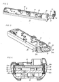
Fig. 2 shows a perspective view of the operation control unit included in the power tool inFig. 1 . -
Fig. 3 shows a fractional perspective view, partly in section, of the circuit board arrangement of the operation control unit inFig. 2 . -
Fig. 4 shows a cross section through the operation control unit. - The power tool illustrated in
Fig. 1 is an electric angle nutrunner including ahousing 10 with a non-illustrated electric motor connected to anoutput shaft 11 extending from anangle head 12 at the forward end of thehousing 10. - At its rear end the
housing 10 is formed with ahandle 13 for manual support of the tool. At the rear end of thehandle 13 there is a non-illustrated connection means for connecting the tool via a cable to a stationary process control unit, and inside thehandle 13 there is supported an electronicoperation control unit 15. The latter is connected to the external connection means at the rear end of the handle as well as to the motor and to operation parameter responsive sensors, like for instance heat a sensor, that are usually supported in thehousing 10. - The
control unit 15 comprises twoprinted circuit boards Figs. 3 and 4 , the printedcircuit boards rigid metal bars circuit boards bars grooves 23a,b and 24a,b, respectively, extending in the longitudinal direction of thebars circuit boards bars circuit boards bars bars copper bars circuit boards - The entire control unit assembly, including the
circuit boards bars tool housing 10 via anonconductive casing 20. The latter is formed as an elongate tray with two parallelinner channels bars casing 20 is formed with atubular portion 27 for proper orientation in the longitudinal direction of thetool housing 10. Preferably, thecasing 20 is made of a suitable plastic material. From the rear end of thecasing 20 there extend two sets ofconductors connectors housing 10. - By designing the
control unit 15 as a subassembly including thecircuit boards board reinforcing bars casing 20 there is obtained a robust preassembled unit which is easy to merge withpower tool housing 10 at the final assembly of the power tool without risking any damage to the separate parts of the control unit.
Claims (5)
- Electric power tool comprising a housing (10), an electric motor, and an onboard operation control unit (15) for motor power supply control, wherein
the control unit (15) comprises
at least one printed circuit board (18,19) carrying electronic components,
characterized in that the control unit (15) comprises at least one rigid metal bar (21,22) extending along at least a part of said circuit board or boards (18,19) and being provided with longitudinal grooves (23a,b, 24a,b) for receiving side edges of said circuit board or boards (18,19), wherein
said at least one metal bar (21,22) is arranged to form a lead for the electric motor current. - Power tool according to claim 1, wherein said metal bars (21,22) are two in number and extend substantially in parallel with each other and along opposite side edges of said at least one printed circuit board (18,19).
- Power tool according to claim 2, wherein said metal bars (21,22) are received in an electrically no-conducting support casing (20) arranged to form a support for said circuit board or boards (18,19) and said metal bars (21,22) relative to the housing (10).
- Power tool according to claim 3, wherein said support casing (20) has the form of a tray with two parallel channels (25,26) for receiving said metal bars (21,22).
- Power tool according to claim 3 or 4, wherein said casing (20) together with said circuit board or boards (18,19) and said metal bars (21,22) form a subassembly for merging with the housing (10) at assembly of the power tool.
Applications Claiming Priority (2)
| Application Number | Priority Date | Filing Date | Title |
|---|---|---|---|
| SE0602574A SE530261C2 (en) | 2006-12-01 | 2006-12-01 | Power tools with an electronic control unit |
| PCT/SE2007/001049 WO2008066453A1 (en) | 2006-12-01 | 2007-11-28 | Power tool with electronic control unit |
Publications (3)
| Publication Number | Publication Date |
|---|---|
| EP2086723A1 EP2086723A1 (en) | 2009-08-12 |
| EP2086723A4 EP2086723A4 (en) | 2010-03-10 |
| EP2086723B1 true EP2086723B1 (en) | 2013-02-13 |
Family
ID=39272896
Family Applications (1)
| Application Number | Title | Priority Date | Filing Date |
|---|---|---|---|
| EP07835240A Not-in-force EP2086723B1 (en) | 2006-12-01 | 2007-11-28 | Power tool with electronic control unit |
Country Status (5)
| Country | Link |
|---|---|
| US (1) | US20100091470A1 (en) |
| EP (1) | EP2086723B1 (en) |
| JP (1) | JP5358453B2 (en) |
| SE (1) | SE530261C2 (en) |
| WO (1) | WO2008066453A1 (en) |
Families Citing this family (5)
| Publication number | Priority date | Publication date | Assignee | Title |
|---|---|---|---|---|
| US10882123B2 (en) | 2015-02-25 | 2021-01-05 | Milwaukee Electric Tool Corporation | Miter saw |
| CN107530873B (en) | 2015-04-24 | 2021-06-29 | 工机控股株式会社 | electrical tools |
| US10078322B2 (en) | 2016-01-08 | 2018-09-18 | Newfrey Llc | Power tool system having in-station verification utilizing radio frequency signal strength |
| US11571800B2 (en) | 2017-02-28 | 2023-02-07 | Mirka Ltd | Cooling arrangement for a power tool and power tool electronics |
| FR3157827B1 (en) * | 2023-12-28 | 2025-12-05 | Renault Georges Ets | portable electric tool with compact electronics |
Family Cites Families (22)
| Publication number | Priority date | Publication date | Assignee | Title |
|---|---|---|---|---|
| US2876277A (en) * | 1954-12-29 | 1959-03-03 | Ibm | Electrical component mounting apparatus |
| JPS5020167U (en) * | 1973-06-15 | 1975-03-07 | ||
| US3991297A (en) * | 1975-02-27 | 1976-11-09 | Bell Telephone Laboratories, Incorporated | Electrically heated soldering device |
| US4400858A (en) * | 1981-01-30 | 1983-08-30 | Tele-Drill Inc, | Heat sink/retainer clip for a downhole electronics package of a measurements-while-drilling telemetry system |
| US4678253A (en) * | 1984-10-29 | 1987-07-07 | Eaton Corporation | Bus duct having improved bus bar clamping structure |
| US4614858A (en) * | 1985-03-28 | 1986-09-30 | Hewlett Packard Company | Electric tool for desoldering surface mounted devices |
| JPS61205168U (en) * | 1985-06-14 | 1986-12-24 | ||
| US4785379A (en) * | 1987-12-04 | 1988-11-15 | Gte Government Systems Corporation | Printed circuit module retainer |
| JPH07100772A (en) * | 1993-10-01 | 1995-04-18 | Ricoh Co Ltd | Rotary power tools |
| US20050072788A1 (en) * | 1998-02-06 | 2005-04-07 | Playtex Products, Inc. | Flow control element for use with leak-proof cup assemblies |
| US6463811B1 (en) * | 1999-04-28 | 2002-10-15 | Snap-On Tools Company | Bending beam torque wrench |
| DE60128418T2 (en) * | 2000-03-16 | 2008-01-17 | Makita Corp., Anjo | Driven impact tool with means for determining the impact noise |
| JP2002026467A (en) * | 2000-06-30 | 2002-01-25 | Mitsubishi Electric Corp | Electronic circuit board |
| US6523442B2 (en) * | 2000-12-07 | 2003-02-25 | Acradyne Inc. | Torque tool assembly |
| US6968759B2 (en) * | 2001-11-14 | 2005-11-29 | Snap-On Incorporated | Electronic torque wrench |
| EP1321237A3 (en) * | 2001-12-18 | 2004-07-07 | The Stanley Works | Electrically powered fastener tool |
| US7090030B2 (en) * | 2002-09-03 | 2006-08-15 | Microtorq L.L.C. | Tranducerized torque wrench |
| JP4076459B2 (en) * | 2003-03-12 | 2008-04-16 | 株式会社オートネットワーク技術研究所 | BUSBAR COMPOSITION BOARD AND CIRCUIT COMPOSITION MANUFACTURING METHOD USING THE SAME |
| CA2634475C (en) * | 2003-07-07 | 2014-05-20 | Brasscorp Limited | Led-based inspection lamp with improved collimation optics |
| US6948380B1 (en) * | 2004-08-23 | 2005-09-27 | Stand Tools Enterprise Co., Ltd. | Torque-indicating wrench |
| US7548411B2 (en) * | 2004-10-29 | 2009-06-16 | Hitachi, Ltd. | Electronic circuit structure, power supply apparatus, power supply system, and electronic apparatus |
| JP2006346795A (en) * | 2005-06-15 | 2006-12-28 | Shinano Seisakusho:Kk | Torque wrench |
-
2006
- 2006-12-01 SE SE0602574A patent/SE530261C2/en not_active IP Right Cessation
-
2007
- 2007-11-28 EP EP07835240A patent/EP2086723B1/en not_active Not-in-force
- 2007-11-28 US US12/517,178 patent/US20100091470A1/en not_active Abandoned
- 2007-11-28 JP JP2009539207A patent/JP5358453B2/en not_active Expired - Fee Related
- 2007-11-28 WO PCT/SE2007/001049 patent/WO2008066453A1/en not_active Ceased
Also Published As
| Publication number | Publication date |
|---|---|
| WO2008066453A1 (en) | 2008-06-05 |
| JP5358453B2 (en) | 2013-12-04 |
| SE0602574L (en) | 2008-04-15 |
| SE530261C2 (en) | 2008-04-15 |
| US20100091470A1 (en) | 2010-04-15 |
| EP2086723A4 (en) | 2010-03-10 |
| JP2010511518A (en) | 2010-04-15 |
| EP2086723A1 (en) | 2009-08-12 |
Similar Documents
| Publication | Publication Date | Title |
|---|---|---|
| EP2322327B1 (en) | Power tool | |
| CN107431158B (en) | Battery packs for hand-held power tools and corresponding hand-held power tools | |
| US20100091470A1 (en) | Power tool with electronic control unit | |
| US20070279870A1 (en) | Electrical connection box | |
| JP4924371B2 (en) | Circuit breaker terminal device | |
| CN101809828B (en) | Power supply connector | |
| US20230178911A1 (en) | Connector for electronically connecting printed circuit boards of an assembly of an electronic control unit for an electric power steering system | |
| CN108063577B (en) | motor drive | |
| JP2008071638A (en) | Assembled battery and manufacturing method of assembled battery | |
| JP4701980B2 (en) | Electric power steering device | |
| CN110365227B (en) | Power conversion device | |
| US11309643B2 (en) | Substrate connecting structure | |
| CN113169472A (en) | Electronic control device and electric power steering device | |
| JP2004066982A (en) | Motor connection fixing structure of steering assembly | |
| US20230397379A1 (en) | Electronic control unit for a vehicle, electric power steering system and vehicle | |
| JP4456519B2 (en) | Electrical junction box | |
| JP5017042B2 (en) | Power connector | |
| JP2008540151A (en) | Portable power tool with motor and electronic control and signal transmission module | |
| JP3971695B2 (en) | Fusible link unit | |
| US20170077832A1 (en) | Electrical machine and power converter | |
| JP4614674B2 (en) | Battery tray device | |
| KR20220059508A (en) | Portable power tool with sensor circuit board | |
| JP5413627B2 (en) | Power supply connector | |
| CN216832233U (en) | 3D printer | |
| EP2842146B1 (en) | Steering column control module |
Legal Events
| Date | Code | Title | Description |
|---|---|---|---|
| PUAI | Public reference made under article 153(3) epc to a published international application that has entered the european phase |
Free format text: ORIGINAL CODE: 0009012 |
|
| 17P | Request for examination filed |
Effective date: 20090528 |
|
| AK | Designated contracting states |
Kind code of ref document: A1 Designated state(s): AT BE BG CH CY CZ DE DK EE ES FI FR GB GR HU IE IS IT LI LT LU LV MC MT NL PL PT RO SE SI SK TR |
|
| A4 | Supplementary search report drawn up and despatched |
Effective date: 20100209 |
|
| DAX | Request for extension of the european patent (deleted) | ||
| RIC1 | Information provided on ipc code assigned before grant |
Ipc: B25F 5/00 20060101ALI20100203BHEP Ipc: H05K 1/02 20060101ALI20100203BHEP Ipc: B25B 23/147 20060101AFI20080620BHEP |
|
| RAP1 | Party data changed (applicant data changed or rights of an application transferred) |
Owner name: ATLAS COPCO INDUSTRIAL TECHNIQUE AB |
|
| GRAP | Despatch of communication of intention to grant a patent |
Free format text: ORIGINAL CODE: EPIDOSNIGR1 |
|
| RIC1 | Information provided on ipc code assigned before grant |
Ipc: H05K 1/02 20060101ALI20121001BHEP Ipc: H05K 7/14 20060101ALI20121001BHEP Ipc: B25F 5/00 20060101ALI20121001BHEP Ipc: B25B 21/00 20060101ALI20121001BHEP Ipc: B25B 23/147 20060101AFI20121001BHEP Ipc: B25B 23/14 20060101ALI20121001BHEP |
|
| GRAS | Grant fee paid |
Free format text: ORIGINAL CODE: EPIDOSNIGR3 |
|
| GRAA | (expected) grant |
Free format text: ORIGINAL CODE: 0009210 |
|
| AK | Designated contracting states |
Kind code of ref document: B1 Designated state(s): AT BE BG CH CY CZ DE DK EE ES FI FR GB GR HU IE IS IT LI LT LU LV MC MT NL PL PT RO SE SI SK TR |
|
| REG | Reference to a national code |
Ref country code: GB Ref legal event code: FG4D |
|
| REG | Reference to a national code |
Ref country code: AT Ref legal event code: REF Ref document number: 596207 Country of ref document: AT Kind code of ref document: T Effective date: 20130215 |
|
| REG | Reference to a national code |
Ref country code: IE Ref legal event code: FG4D |
|
| REG | Reference to a national code |
Ref country code: DE Ref legal event code: R096 Ref document number: 602007028450 Country of ref document: DE Effective date: 20130411 |
|
| REG | Reference to a national code |
Ref country code: AT Ref legal event code: MK05 Ref document number: 596207 Country of ref document: AT Kind code of ref document: T Effective date: 20130213 |
|
| REG | Reference to a national code |
Ref country code: NL Ref legal event code: VDEP Effective date: 20130213 |
|
| REG | Reference to a national code |
Ref country code: LT Ref legal event code: MG4D |
|
| PG25 | Lapsed in a contracting state [announced via postgrant information from national office to epo] |
Ref country code: LT Free format text: LAPSE BECAUSE OF FAILURE TO SUBMIT A TRANSLATION OF THE DESCRIPTION OR TO PAY THE FEE WITHIN THE PRESCRIBED TIME-LIMIT Effective date: 20130213 Ref country code: IS Free format text: LAPSE BECAUSE OF FAILURE TO SUBMIT A TRANSLATION OF THE DESCRIPTION OR TO PAY THE FEE WITHIN THE PRESCRIBED TIME-LIMIT Effective date: 20130613 Ref country code: SE Free format text: LAPSE BECAUSE OF FAILURE TO SUBMIT A TRANSLATION OF THE DESCRIPTION OR TO PAY THE FEE WITHIN THE PRESCRIBED TIME-LIMIT Effective date: 20130213 Ref country code: AT Free format text: LAPSE BECAUSE OF FAILURE TO SUBMIT A TRANSLATION OF THE DESCRIPTION OR TO PAY THE FEE WITHIN THE PRESCRIBED TIME-LIMIT Effective date: 20130213 Ref country code: ES Free format text: LAPSE BECAUSE OF FAILURE TO SUBMIT A TRANSLATION OF THE DESCRIPTION OR TO PAY THE FEE WITHIN THE PRESCRIBED TIME-LIMIT Effective date: 20130524 Ref country code: BG Free format text: LAPSE BECAUSE OF FAILURE TO SUBMIT A TRANSLATION OF THE DESCRIPTION OR TO PAY THE FEE WITHIN THE PRESCRIBED TIME-LIMIT Effective date: 20130513 |
|
| PG25 | Lapsed in a contracting state [announced via postgrant information from national office to epo] |
Ref country code: PL Free format text: LAPSE BECAUSE OF FAILURE TO SUBMIT A TRANSLATION OF THE DESCRIPTION OR TO PAY THE FEE WITHIN THE PRESCRIBED TIME-LIMIT Effective date: 20130213 Ref country code: BE Free format text: LAPSE BECAUSE OF FAILURE TO SUBMIT A TRANSLATION OF THE DESCRIPTION OR TO PAY THE FEE WITHIN THE PRESCRIBED TIME-LIMIT Effective date: 20130213 Ref country code: SI Free format text: LAPSE BECAUSE OF FAILURE TO SUBMIT A TRANSLATION OF THE DESCRIPTION OR TO PAY THE FEE WITHIN THE PRESCRIBED TIME-LIMIT Effective date: 20130213 Ref country code: FI Free format text: LAPSE BECAUSE OF FAILURE TO SUBMIT A TRANSLATION OF THE DESCRIPTION OR TO PAY THE FEE WITHIN THE PRESCRIBED TIME-LIMIT Effective date: 20130213 Ref country code: GR Free format text: LAPSE BECAUSE OF FAILURE TO SUBMIT A TRANSLATION OF THE DESCRIPTION OR TO PAY THE FEE WITHIN THE PRESCRIBED TIME-LIMIT Effective date: 20130514 Ref country code: LV Free format text: LAPSE BECAUSE OF FAILURE TO SUBMIT A TRANSLATION OF THE DESCRIPTION OR TO PAY THE FEE WITHIN THE PRESCRIBED TIME-LIMIT Effective date: 20130213 Ref country code: PT Free format text: LAPSE BECAUSE OF FAILURE TO SUBMIT A TRANSLATION OF THE DESCRIPTION OR TO PAY THE FEE WITHIN THE PRESCRIBED TIME-LIMIT Effective date: 20130613 |
|
| PG25 | Lapsed in a contracting state [announced via postgrant information from national office to epo] |
Ref country code: RO Free format text: LAPSE BECAUSE OF FAILURE TO SUBMIT A TRANSLATION OF THE DESCRIPTION OR TO PAY THE FEE WITHIN THE PRESCRIBED TIME-LIMIT Effective date: 20130213 Ref country code: EE Free format text: LAPSE BECAUSE OF FAILURE TO SUBMIT A TRANSLATION OF THE DESCRIPTION OR TO PAY THE FEE WITHIN THE PRESCRIBED TIME-LIMIT Effective date: 20130213 Ref country code: SK Free format text: LAPSE BECAUSE OF FAILURE TO SUBMIT A TRANSLATION OF THE DESCRIPTION OR TO PAY THE FEE WITHIN THE PRESCRIBED TIME-LIMIT Effective date: 20130213 Ref country code: CZ Free format text: LAPSE BECAUSE OF FAILURE TO SUBMIT A TRANSLATION OF THE DESCRIPTION OR TO PAY THE FEE WITHIN THE PRESCRIBED TIME-LIMIT Effective date: 20130213 Ref country code: DK Free format text: LAPSE BECAUSE OF FAILURE TO SUBMIT A TRANSLATION OF THE DESCRIPTION OR TO PAY THE FEE WITHIN THE PRESCRIBED TIME-LIMIT Effective date: 20130213 Ref country code: NL Free format text: LAPSE BECAUSE OF FAILURE TO SUBMIT A TRANSLATION OF THE DESCRIPTION OR TO PAY THE FEE WITHIN THE PRESCRIBED TIME-LIMIT Effective date: 20130213 |
|
| PLBE | No opposition filed within time limit |
Free format text: ORIGINAL CODE: 0009261 |
|
| STAA | Information on the status of an ep patent application or granted ep patent |
Free format text: STATUS: NO OPPOSITION FILED WITHIN TIME LIMIT |
|
| 26N | No opposition filed |
Effective date: 20131114 |
|
| REG | Reference to a national code |
Ref country code: DE Ref legal event code: R097 Ref document number: 602007028450 Country of ref document: DE Effective date: 20131114 |
|
| REG | Reference to a national code |
Ref country code: CH Ref legal event code: PL |
|
| PG25 | Lapsed in a contracting state [announced via postgrant information from national office to epo] |
Ref country code: CH Free format text: LAPSE BECAUSE OF NON-PAYMENT OF DUE FEES Effective date: 20131130 Ref country code: LI Free format text: LAPSE BECAUSE OF NON-PAYMENT OF DUE FEES Effective date: 20131130 Ref country code: MC Free format text: LAPSE BECAUSE OF FAILURE TO SUBMIT A TRANSLATION OF THE DESCRIPTION OR TO PAY THE FEE WITHIN THE PRESCRIBED TIME-LIMIT Effective date: 20130213 |
|
| REG | Reference to a national code |
Ref country code: IE Ref legal event code: MM4A |
|
| PG25 | Lapsed in a contracting state [announced via postgrant information from national office to epo] |
Ref country code: IE Free format text: LAPSE BECAUSE OF NON-PAYMENT OF DUE FEES Effective date: 20131128 |
|
| PG25 | Lapsed in a contracting state [announced via postgrant information from national office to epo] |
Ref country code: TR Free format text: LAPSE BECAUSE OF FAILURE TO SUBMIT A TRANSLATION OF THE DESCRIPTION OR TO PAY THE FEE WITHIN THE PRESCRIBED TIME-LIMIT Effective date: 20130213 Ref country code: CY Free format text: LAPSE BECAUSE OF FAILURE TO SUBMIT A TRANSLATION OF THE DESCRIPTION OR TO PAY THE FEE WITHIN THE PRESCRIBED TIME-LIMIT Effective date: 20130213 |
|
| PG25 | Lapsed in a contracting state [announced via postgrant information from national office to epo] |
Ref country code: LU Free format text: LAPSE BECAUSE OF NON-PAYMENT OF DUE FEES Effective date: 20131128 Ref country code: HU Free format text: LAPSE BECAUSE OF FAILURE TO SUBMIT A TRANSLATION OF THE DESCRIPTION OR TO PAY THE FEE WITHIN THE PRESCRIBED TIME-LIMIT; INVALID AB INITIO Effective date: 20071128 |
|
| PG25 | Lapsed in a contracting state [announced via postgrant information from national office to epo] |
Ref country code: MT Free format text: LAPSE BECAUSE OF FAILURE TO SUBMIT A TRANSLATION OF THE DESCRIPTION OR TO PAY THE FEE WITHIN THE PRESCRIBED TIME-LIMIT Effective date: 20130213 |
|
| REG | Reference to a national code |
Ref country code: FR Ref legal event code: PLFP Year of fee payment: 9 |
|
| REG | Reference to a national code |
Ref country code: FR Ref legal event code: PLFP Year of fee payment: 10 |
|
| REG | Reference to a national code |
Ref country code: FR Ref legal event code: PLFP Year of fee payment: 11 |
|
| PGFP | Annual fee paid to national office [announced via postgrant information from national office to epo] |
Ref country code: DE Payment date: 20191127 Year of fee payment: 13 |
|
| PGFP | Annual fee paid to national office [announced via postgrant information from national office to epo] |
Ref country code: FR Payment date: 20191125 Year of fee payment: 13 Ref country code: IT Payment date: 20191125 Year of fee payment: 13 |
|
| PGFP | Annual fee paid to national office [announced via postgrant information from national office to epo] |
Ref country code: GB Payment date: 20191127 Year of fee payment: 13 |
|
| REG | Reference to a national code |
Ref country code: DE Ref legal event code: R119 Ref document number: 602007028450 Country of ref document: DE |
|
| GBPC | Gb: european patent ceased through non-payment of renewal fee |
Effective date: 20201128 |
|
| PG25 | Lapsed in a contracting state [announced via postgrant information from national office to epo] |
Ref country code: IT Free format text: LAPSE BECAUSE OF NON-PAYMENT OF DUE FEES Effective date: 20201128 Ref country code: FR Free format text: LAPSE BECAUSE OF NON-PAYMENT OF DUE FEES Effective date: 20201130 |
|
| PG25 | Lapsed in a contracting state [announced via postgrant information from national office to epo] |
Ref country code: DE Free format text: LAPSE BECAUSE OF NON-PAYMENT OF DUE FEES Effective date: 20210601 Ref country code: GB Free format text: LAPSE BECAUSE OF NON-PAYMENT OF DUE FEES Effective date: 20201128 |