EP2086239A2 - Block encoding mode prediction for video coding - Google Patents
Block encoding mode prediction for video coding Download PDFInfo
- Publication number
- EP2086239A2 EP2086239A2 EP20090151276 EP09151276A EP2086239A2 EP 2086239 A2 EP2086239 A2 EP 2086239A2 EP 20090151276 EP20090151276 EP 20090151276 EP 09151276 A EP09151276 A EP 09151276A EP 2086239 A2 EP2086239 A2 EP 2086239A2
- Authority
- EP
- European Patent Office
- Prior art keywords
- video
- block
- video component
- mode
- component block
- Prior art date
- Legal status (The legal status is an assumption and is not a legal conclusion. Google has not performed a legal analysis and makes no representation as to the accuracy of the status listed.)
- Withdrawn
Links
Images


Classifications
-
- H—ELECTRICITY
- H04—ELECTRIC COMMUNICATION TECHNIQUE
- H04N—PICTORIAL COMMUNICATION, e.g. TELEVISION
- H04N19/00—Methods or arrangements for coding, decoding, compressing or decompressing digital video signals
- H04N19/10—Methods or arrangements for coding, decoding, compressing or decompressing digital video signals using adaptive coding
- H04N19/102—Methods or arrangements for coding, decoding, compressing or decompressing digital video signals using adaptive coding characterised by the element, parameter or selection affected or controlled by the adaptive coding
- H04N19/103—Selection of coding mode or of prediction mode
-
- H—ELECTRICITY
- H04—ELECTRIC COMMUNICATION TECHNIQUE
- H04N—PICTORIAL COMMUNICATION, e.g. TELEVISION
- H04N19/00—Methods or arrangements for coding, decoding, compressing or decompressing digital video signals
- H04N19/10—Methods or arrangements for coding, decoding, compressing or decompressing digital video signals using adaptive coding
- H04N19/169—Methods or arrangements for coding, decoding, compressing or decompressing digital video signals using adaptive coding characterised by the coding unit, i.e. the structural portion or semantic portion of the video signal being the object or the subject of the adaptive coding
- H04N19/186—Methods or arrangements for coding, decoding, compressing or decompressing digital video signals using adaptive coding characterised by the coding unit, i.e. the structural portion or semantic portion of the video signal being the object or the subject of the adaptive coding the unit being a colour or a chrominance component
-
- H—ELECTRICITY
- H04—ELECTRIC COMMUNICATION TECHNIQUE
- H04N—PICTORIAL COMMUNICATION, e.g. TELEVISION
- H04N19/00—Methods or arrangements for coding, decoding, compressing or decompressing digital video signals
- H04N19/10—Methods or arrangements for coding, decoding, compressing or decompressing digital video signals using adaptive coding
- H04N19/102—Methods or arrangements for coding, decoding, compressing or decompressing digital video signals using adaptive coding characterised by the element, parameter or selection affected or controlled by the adaptive coding
- H04N19/103—Selection of coding mode or of prediction mode
- H04N19/11—Selection of coding mode or of prediction mode among a plurality of spatial predictive coding modes
-
- H—ELECTRICITY
- H04—ELECTRIC COMMUNICATION TECHNIQUE
- H04N—PICTORIAL COMMUNICATION, e.g. TELEVISION
- H04N19/00—Methods or arrangements for coding, decoding, compressing or decompressing digital video signals
- H04N19/10—Methods or arrangements for coding, decoding, compressing or decompressing digital video signals using adaptive coding
- H04N19/102—Methods or arrangements for coding, decoding, compressing or decompressing digital video signals using adaptive coding characterised by the element, parameter or selection affected or controlled by the adaptive coding
- H04N19/119—Adaptive subdivision aspects, e.g. subdivision of a picture into rectangular or non-rectangular coding blocks
-
- H—ELECTRICITY
- H04—ELECTRIC COMMUNICATION TECHNIQUE
- H04N—PICTORIAL COMMUNICATION, e.g. TELEVISION
- H04N19/00—Methods or arrangements for coding, decoding, compressing or decompressing digital video signals
- H04N19/10—Methods or arrangements for coding, decoding, compressing or decompressing digital video signals using adaptive coding
- H04N19/134—Methods or arrangements for coding, decoding, compressing or decompressing digital video signals using adaptive coding characterised by the element, parameter or criterion affecting or controlling the adaptive coding
- H04N19/136—Incoming video signal characteristics or properties
- H04N19/14—Coding unit complexity, e.g. amount of activity or edge presence estimation
-
- H—ELECTRICITY
- H04—ELECTRIC COMMUNICATION TECHNIQUE
- H04N—PICTORIAL COMMUNICATION, e.g. TELEVISION
- H04N19/00—Methods or arrangements for coding, decoding, compressing or decompressing digital video signals
- H04N19/10—Methods or arrangements for coding, decoding, compressing or decompressing digital video signals using adaptive coding
- H04N19/169—Methods or arrangements for coding, decoding, compressing or decompressing digital video signals using adaptive coding characterised by the coding unit, i.e. the structural portion or semantic portion of the video signal being the object or the subject of the adaptive coding
- H04N19/17—Methods or arrangements for coding, decoding, compressing or decompressing digital video signals using adaptive coding characterised by the coding unit, i.e. the structural portion or semantic portion of the video signal being the object or the subject of the adaptive coding the unit being an image region, e.g. an object
- H04N19/176—Methods or arrangements for coding, decoding, compressing or decompressing digital video signals using adaptive coding characterised by the coding unit, i.e. the structural portion or semantic portion of the video signal being the object or the subject of the adaptive coding the unit being an image region, e.g. an object the region being a block, e.g. a macroblock
-
- H—ELECTRICITY
- H04—ELECTRIC COMMUNICATION TECHNIQUE
- H04N—PICTORIAL COMMUNICATION, e.g. TELEVISION
- H04N19/00—Methods or arrangements for coding, decoding, compressing or decompressing digital video signals
- H04N19/50—Methods or arrangements for coding, decoding, compressing or decompressing digital video signals using predictive coding
- H04N19/503—Methods or arrangements for coding, decoding, compressing or decompressing digital video signals using predictive coding involving temporal prediction
- H04N19/51—Motion estimation or motion compensation
-
- H—ELECTRICITY
- H04—ELECTRIC COMMUNICATION TECHNIQUE
- H04N—PICTORIAL COMMUNICATION, e.g. TELEVISION
- H04N19/00—Methods or arrangements for coding, decoding, compressing or decompressing digital video signals
- H04N19/50—Methods or arrangements for coding, decoding, compressing or decompressing digital video signals using predictive coding
Definitions
- the present invention relates to a video encoding method and apparatus, and a video decoding method and apparatus, and more particularly, to a video encoding method and apparatus, and a video decoding method and apparatus, which are capable of improving efficiency of encoding a luminance component video signal by predicting information on various encoding modes of the luminance component video signal by using a result obtained by encoding a chrominance component video signal.
- an initial video has an RGB color format when video images are captured.
- a video having the RGB color format is generally encoded into a video having a YUV (or YCbCr) color format.
- a Y component indicates luminance data including brightness information
- U (or Cb) and V (or Cr) components indicate chrominance data including color information.
- information is uniformly distributed over R, G, and B.
- YUV (or YCbCr) video information is concentrated on the Y component, and the amount of information on the U (or Cb) and V (or Cr) components is reduced. This is advantageous in that a compression rate is increased when compressing a YUV video.
- a YUV (or YCbCr) 4:2:0 video is used by sampling chrominance components U (or Cb) and V (or Cr) of the YUV (or YCbCr) video with a 1/4 size of the luminance component.
- the YUV (or YCbCr) video is compressed, in general, the Y component is encoded independently of the U (or Cb) and V (or Cr) components.
- MPEG-4 AVC/H.264 standard of the Joint Video Team (JVT) of ISO/IEC MPEG and ITU-T VCEG
- JVT Joint Video Team
- ITU-T VCEG ITU-T VCEG
- MPEG-4 AVC/H.264 when the Y component is intra-video encoded, a spatial prediction process is performed by using nine prediction methods in units of 4x4 blocks along a prediction direction. In addition, the spatial prediction process is performed by using four prediction methods in units of 16x16 blocks along the prediction direction.
- U (or Cb) and V (or Cr) component video signals are relatively simple compared with a Y component video signal
- the spatial prediction process is performed with respect to the U and V component video signals by using four prediction methods in units of 8x8 blocks along the prediction direction independently of the Y component video.
- the Y component video signal When the Y component video signal is inter-video encoded, a motion is accurately compensated for, by expanding a predicted video signal by using a 6-tap filter.
- the U (or Cb) and V (or Cr) component video signals are inter-video encoded, a motion is compensated for by using a bilinear filter.
- the Y component video signal and the U (or Cb) and V (or Cr) component video signals are compressed by using independent methods.
- the present invention provides a method and apparatus for encoding a video signal, and a method and apparatus for decoding the encoded video signal, which are capable of improving efficiency of encoding a luminance component video signal by predicting an encoding mode of the luminance component video signal from an encoded and recovered chrominance video signal by using a correlation between the chrominance component video signal and the luminance component video signal.
- a video encoding method including the operations of: encoding a first video component block of a predetermined size from a current video signal comprising at least two video components and recovering the encoded first video component block; predicting an encoding mode of a second video component block corresponding to the first video component block by using the recovered first video component block; and encoding the second video component block according to the predicted encoding mode.
- a video encoding apparatus including: an encoding mode prediction unit which predicts an encoding mode of a second video component block corresponding to a first video component block by using a first video component of a predetermined size which is previously encoded and recovered in a current video signal comprising at least two video components; and an encoding unit which encodes the second video component block according to the predicted encoding mode.
- a video decoding method including the operations of: decoding a first video component block of a predetermined size from a current video signal comprising at least two video components; predicting a decoding mode of a second video component block corresponding to the first video component block by using the decoded first video component block; and decoding the second video component block according to the predicted decoding mode.
- a video decoding apparatus including: a decoding mode prediction unit which predicts a decoding mode of a second video component block corresponding to a first video component block by using the first video component of predetermined size which is previously decoded in a current video signal comprising at least two video components; and a decoding unit which decodes the second video component block according to the predicted decoding mode.
- a luminance component video signal and a chrominance component video signal are encoded by using independent methods. This is because the amount of chrominance component data is less than that of luminance component data.
- the chrominance component video signal has less data than the luminance component video
- an edge component existing in a video commonly tends to exist in both the chrominance component video signal and the luminance component video signal. That is, in a case where an edge is detected in the chrominance component video signal, an edge may be also detected in the luminance component video signal. Directionality and a position of the detected edge may be the same in both the chrominance component video signal and the luminance component video signal.
- a macroblock is generally divided into sub-blocks having a smaller size and decoded.
- a block mode for representing a divided form of the macroblock tends to be the same in both the chrominance component video signal and the luminance component video signal. Accordingly, in the present invention, various encoding modes are predicted by using a result obtained by encoding a chrominance component video that is encoded and recovered, and the luminance component video is encoded by applying the predicted encoding mode.
- the encoding mode includes a block mode for representing a divided form of a block obtained when a block of predetermined size is encoded and an intra-prediction mode obtained when the block of predetermined size is intra-predicted.
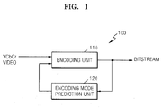
- FIG. 1 is a block diagram illustrating a structure of a video encoding apparatus according to an embodiment of the present invention.
- a video encoding apparatus 100 includes an encoding unit 110 and an encoding mode prediction unit 120.
- the encoding unit 110 firstly encodes a CbCr video signal that is a chrominance component video signal of an input YCbCr video signal. Specifically, the encoding unit 110 divides an input chrominance component video signal into macroblocks. A predicted video signal is generated by performing intra-prediction and inter-prediction processes with respect to the macroblocks. Bitstreams are generated by quantizing and entropy-encoding a difference between the predicted video signal and the input video signal. When encoding of the chrominance component video signal is completed, it is possible to determine encoding modes in which the macroblocks are encoded.
- the encoding unit 110 encodes the macroblocks of the chrominance component video signal by applying various available encoding modes in the inter-prediction process and the intra-prediction process, compares costs of the bitstreams generated in the encoding mode with one another, and determines a prediction mode having the least cost, for example, a rate-distortion (RD) cost, as a final encoding mode of macroblocks of the chrominance component video signal.
- RD rate-distortion
- the encoding unit 110 begins to encode the luminance component video signal after encoding the chrominance component video.
- the encoding unit 110 encodes the luminance component video signal by using the encoding mode that is predicted by using information on the encoding mode of the chrominance component video signal determined by using a result of encoding the chrominance component video signal and by using a correlation between the chrominance component and the luminance component.
- the encoding mode prediction unit 120 predicts the encoding mode of the corresponding luminance component video signal by using the chrominance component video signal that is encoded by the encoding unit 110 and recovered.
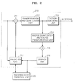
- FIG. 2 is a block diagram illustrating an encoding unit 110 shown in FIG. 1 according to an embodiment of the present invention.
- a reference numeral 210 corresponds to the encoding unit 110 of FIG. 1 .
- the encoding unit 210 according to the current embodiment based on the MPEG-4 H.264/AVC standard is shown in FIG. 2 , the encoding unit is not limited thereto. Various widely known compression-encoding apparatuses may be applied to the encoding unit 210.
- the encoding unit 210 includes a subtraction unit 211, a transformation and quantization unit 212, an entropy encoding unit 213, an inverse transformation and inverse quantization unit 214, an adding unit 215, a storage unit 216, and a prediction unit 217.
- the prediction unit 217 generates a predicted chrominance component video signal by performing inter-prediction and intra-prediction processes with respect to a predetermined size of blocks of the chrominance component video. Specifically, when the inter-prediction process is performed with respect to the chrominance component video block, a motion vector is generated by predicting a motion of a current chrominance component video block in a predetermined area of a reference picture, and a predicted block is generated by acquiring an area of the reference picture pointed to by the motion vector.
- a predicted chrominance component video block is generated by extending pixels of surrounding blocks which are previously encoded and recovered.
- the subtraction unit 211 generates a residual chrominance component video block by subtracting the predicted chrominance component video block from the input chrominance component video block.
- the generated residual chrominance component video block is transformed and quantized by using the transformation and quantization unit 212.
- the entropy encoding unit 213 generates bitstreams by entropy-encoding the transformed and quantized residual chrominance component video block.
- the transformed and quantized residual chrominance component video block is inverse-quantized and inverse-transformed by the inverse quantization and inverse transformation unit 214.
- the adding unit 215 recovers the chrominance component video block by adding the inverse-quantized and inverse-transformed residual chrominance component video block to the predicted chrominance component video block and stores the recovered chrominance component video block in the storage unit 216.
- An encoding mode prediction unit 220 predicts an encoding mode of a luminance component video signal by using the recovered chrominance component video signal. Specifically, the encoding mode prediction unit 220 may predict a block mode of the luminance component video block by calculating the complexity of the chrominance component video block. In addition, the encoding mode prediction unit 220 may predict a block mode of a luminance component video signal corresponding to a divided form of the chrominance component video block. In addition, the encoding mode prediction unit 220 predicts an intra-prediction mode of the luminance component video block by using directionality of an edge existing in the chrominance component video block. In addition, the encoding mode prediction unit 220 may determine a divided form of the luminance component video by using the edge existing in the chrominance component video block.
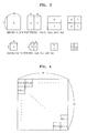
- FIG. 3 illustrates a method of dividing a macroblock.
- a 16x16 macroblock may be divided into sub-blocks having various sizes such as 16x16, 16x8, 8x16, and 8x8 and then encoded.
- a block having a size of 8x8 may be divided into sub-blocks having sizes such as 8x8, 8x4, 4x8, and 4x4 and then encoded.
- the complexity of the macroblock in a case where the complexity of the macroblock is low, it is efficient to encode macroblocks having large sizes such as 16x16, 16x8, and 8x16.
- the complexity of the macroblock is high, it is suitable to divide macroblocks into smaller form of sub-blocks and encode the sub-blocks.
- the encoding mode prediction unit 220 determines a divided form of the recovered chrominance component video block, that is, the block mode, by dividing the chrominance component video block into sub-blocks according to the complexity of the recovered chrominance component video block and repeatedly dividing the sub-blocks into smaller sub-blocks according to the complexities of the sub-blocks.
- the encoding mode prediction unit 220 predicts the block mode of the determined chrominance component video block as the block mode of the luminance component video block.
- the complexity of the chrominance component video block may be calculated by using various algorithms. For example, it is possible to calculate the complexity by detecting edges in a block and calculating the amount of detected edges by using the Canny edge detection algorithm and the Sobel edge detection algorithm. Alternatively, it is possible to calculate the complexity by adding up gradients of pixels in the chrominance component video block.
- FIG. 4 illustrates a procedure for calculating the complexity of a chrominance component image block according to an embodiment of the present invention.
- P(i,j) indicates a value of a pixel located at an i-th row and a j-th column.
- the complexity G of a 16x16 chrominance component video block may be calculated by adding up gradients, as shown in Equation 1.
- a gradient at a pixel (i,j) is calculated by adding a difference in pixel values between the pixel (i,j) and a left pixel (i-1,j) thereof to a difference in pixel values between the pixel (i,j) and an upper pixel (i, j-1) thereof.
- the gradient may be calculated by using various methods. For example, it is possible to determine a gradient by calculating a difference in pixel value between a pixel and another pixel spaced apart therefrom by predetermined pixels.
- a clear edge area in the Cb component will be an unclear edge area in the Cr component.
- a clear edge area in the Cr component will be an unclear edge area in the Cb component. Accordingly, block complexities calculated in the Cb and Cr components have a complementary relationship with each other.
- a complexity calculated by using a first chrominance component Cb is G1
- a complexity calculated by using a second chrominance component Cr is G2.
- the complexity of the current block may be defined as the maximum value of the complexities G1 and G2 or the sum of the complexities G1 and G2.
- the encoding mode prediction unit 120 maintains the form of the 16x16 chrominance component video block. In a case where the calculated complexity of the 16x16 chrominance component video block is greater than a predetermined threshold T16, the encoding mode prediction unit 120 divides the 16x16 chrominance component video block into sub-blocks, for example 8x8 sub-blocks.
- the encoding mode prediction unit 120 calculates the complexity of each 8x8 sub-blocks and compares the complexity of each 8x8 sub-block with a predetermined threshold T8 and divides 8x8 sub-blocks having a complexity greater than the threshold T8 into sub-blocks, for example, 4x4 sub-blocks.
- the procedure of dividing a block into sub-blocks may not be performed with respect to sub-blocks having a smaller size than 4x4 sub-blocks.
- An example of a chrominance component video block obtained through the aforementioned procedure is shown in FIG. 5 .
- the encoding mode prediction unit 120 When the block mode of the chrominance component video block is determined, the encoding mode prediction unit 120 outputs information on the block mode of the chrominance component video block to the encoding unit 110.
- the encoding unit 110 divides the luminance component video block and encodes the divided luminance component video block in the same block mode as the chrominance component video block.
- the encoding unit 110 independently determines a block mode of the luminance component video signal according to a general block mode determination algorithm and encodes information on a difference between the block mode predicted from the information on the block mode of the chrominance component video signal and the block mode in which a block is divided according to a practical procedure of determining a block mode as information on the block mode.
- a predetermined value is defined according to a divided form of each macroblock.
- a difference between block modes may be encoded as information on a block mode. For example, it is assumed that it is previously determined that the block mode of the macroblock to be encoded with a size of 16x16 is 0, and the block mode of the macroblock to be divided into sub-blocks with a size of 8x8 and encoded is 1. If a block mode determined by dividing the chrominance component video block according to the complexity thereof is 1 and if a block mode determined through a procedure of determining a block mode with respect to the luminance component video block is 0, it is possible to transmit only a difference value of 1 between the block modes of the luminance component video block.
- the luminance component video block by dividing the luminance component video block by using a block mode of the chrominance component video block by omitting a practical procedure of determining a block mode for the luminance component video block.
- the encoding mode prediction unit 120 detects directionality of an edge existing in the chrominance component video block by using the recovered chrominance component video block.
- the edge existing in the chrominance component video block may be detected by using various algorithms for detecting edges such as the Canny edge detection algorithm, the Sobel algorithm, and the like.
- the edge may be detected by calculating a gradient for each pixel in the block and using pixels having relatively large gradients.
- FIG. 6 illustrates an example of an edge in a chrominance component video block.
- FIG. 6 in a case where an edge exists in a chrominance component video block 610, both areas divided by the edge are considerably different from each other. Accordingly, when the intra-prediction process is performed, it is desirable to determine the intra-prediction direction so as to determine the intra-prediction mode in consideration of the directionality of the edge.
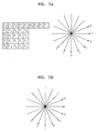
- FIGS. 7A and 7B are reference views for illustrating a predicted direction and a prediction method based on an intra-prediction mode.
- FIG. 7A illustrates pixels of a current block to be intra-predicted and surrounding pixels of the current block.
- FIG. 7B illustrates available intra-prediction modes in the case of a 4x4 pixel block.
- FIG. 7B when intra-predicting a 4x4 block, one of nine prediction directions is determined as a prediction direction. A predicted video is generated by applying the determined prediction direction. For example, as shown in FIG. 7A , previously encoded and recovered neighboring data P0 to P12 is used to predict 4x4 block data Pa to Pq. If the 4x4 block is intra-predicted in a mode 0 (vertical) from among the intra-prediction modes shown in FIG.
- P1, P2, P3, and P4 are vertically extended, thus the pixel values of Pa, Pe, Pi and Pm are predicted from P1, the pixel values of Pb, Pf, Pj and Pn are predicted from P2, the pixel values of Pc, Pg, Pk, and Po are predicted from P3, and the pixel values of Pd, Ph, P1, and Pq are predicted from P4.
- a predicted video is generated by determining one of the nine prediction directions as a prediction direction similarly to the intra-prediction process for the 4x4 block.
- a predicted video is generated by determining one of four prediction directions (horizontal, vertical, DC, and plane directions) as a prediction direction.
- the encoding mode prediction unit 120 detects a directionality of an edge existing in the chrominance component video block and outputs the detected directionality to the encoding unit 110. Then, the encoding unit 110 performs the intra-predict process with respect to the luminance component video block by applying the intra-prediction mode in a direction that is most similar to the direction of the edge existing in the chrominance component video block. For example, as shown in FIG.
- the intra-prediction process is performed with respect to the luminance component video block by applying the intra-prediction mode 4 with a directionality that is most similar to the direction of an edge existing in the luminance component video block 610, from among the various intra-prediction modes.
- the encoding unit 110 determines the intra-prediction mode by independently performing the intra-prediction process with respect to the luminance component video and encodes only information on a difference between the intra-prediction mode predicted by using the directionality of the edge detected in the chrominance component video block and the intra-prediction mode determined by the practical intra-prediction process as information on the intra-prediction mode of the luminance component video block. For example, if an intra-prediction mode that is predicted by using the chrominance component video block is 4 and if an intra-prediction mode that is finally determined by applying various intra-prediction modes to corresponding luminance component video blocks is 5, only a difference of 1 between the intra-prediction modes may be transmitted as information on the intra-prediction mode. On the other hand, the encoding unit 110 may determine the intra-prediction mode of the luminance component video block, which is predicted by using the chrominance component video block, as the intra-prediction mode of the luminance component video block, as it is.
- the encoding unit 110 performs an encoding process by dividing the luminance component video block into various shapes of blocks by using edges existing in the chrominance component video block unlike the conventional method of performing an encoding process by dividing macroblocks into N x M blocks. As shown in FIG. 6 , when an edge is detected in the chrominance component video block 610, the encoding process is performed by dividing the luminance component video block by using the detected edge.
- the luminance component video block is divided and decoded by using the same procedure as at an encoding end by inserting predetermined binary information on whether the block is divided by using the edge detected in the chrominance component video block into a predetermined area of a bitstream generated by encoding the luminance component video block.
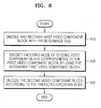
- FIG. 8 is a flowchart illustrating a video encoding method according to an embodiment of the present invention.
- a first video component block with a predetermined size included in a current video signal comprising at least two video components is encoded and recovered.
- the first video component is a chrominance component
- the chrominance component video signal is firstly encoded and recovered.
- an encoding mode of a second video component block corresponding to the first video component block is predicted by using the recovered first video component block.
- an encoding mode of a luminance component video block is predicted by using the chrominance component video block.
- the block mode of the luminance component video block that is currently encoded is predicted by using the block mode for representing a divided form of the chrominance component video block.
- the intra-prediction mode to be applied when intra-predicting the luminance component video block is predicted by using the directionality of an edge existing in the chrominance component video block.
- the luminance component video block may be divided by using the edge existing in the chrominance component video block and then encoded.
- the second video component block is encoded based on the predicted encoding mode.
- the luminance component video block may be encoded by applying the encoding mode predicted by using the chrominance component video to the luminance component video block.
- only a difference in encoding modes between the luminance component video block and the chrominance component video block may be encoded as information on the encoding mode.
- a cost of a bitstream of a luminance component video encoded by using the encoding mode predicted by using the chrominance component video signal in consideration of a correlation with the chrominance component video signal according to the present invention is compared with a cost of a bitstream of a luminance component video signal independently encoded without considering the correlation with the chrominance component video signal according to a conventional technique.
- An encoding mode used to generate a bitstream at least cost is determined as a final encoding mode of the luminance component video signal.
- Information on the determined final encoding mode is added to a predetermined area of the bitstream of the encoded luminance component video signal.
- the encoding mode of the bitstream of the luminance component video encoded by using an encoding mode predicted by using the chrominance component video signal in consideration of the correlation with the chrominance component video signal is set to 1
- the encoding mode of the bitstream of the luminance component video signal independently encoded without considering the correlation with the chrominance component video signal according to the conventional technique is set to 0.
- the decoding device determines whether the luminance component video signal that is currently to be decoded is encoded by using the encoding mode predicted in consideration of the correlation with the previously encoded chrominance component video signal or encoded independently of the chrominance component video signal by using the information on the encoding mode.
- the decoding device determines whether the luminance component video block that is currently to be decoded is encoded according to the current embodiment or encoded according to the conventional technique by extracting information on the encoding mode for representing whether the encoding mode of the luminance component video block is predicted by using the chrominance component video block from the bitstream. As described above, if the information on the encoding mode of the luminance component is 1, the decoding mode of the current luminance component video block to be decoded is predicted by using a block corresponding to the previously decoded chrominance component video block, and the current luminance component video block is decoded according to the predicted decoding mode.
- the current luminance component video block is decoded independently of a block corresponding to the chrominance component video block according to the conventional technique. It is possible for the conventional decoding apparatus to recognize whether the bitstream is encoded according to the current embodiment or encoded according to the conventional technique by allowing the decoding apparatus to determine whether the current embodiment is applied by using the information on the encoding mode using predetermined binary information.
- the present invention may be applicable when encoding a video signal having a plurality of video components.
- FIG. 9 is a block diagram illustrating a structure of a video decoding apparatus according to an embodiment of the present invention.
- FIG. 10 is a detailed block diagram illustrating a decoding unit 910 of FIG. 9 .
- a video decoding apparatus 900 includes the decoding unit 910 and a decoding mode prediction unit 920.
- the decoding unit 910 firstly decodes the chrominance component video signal included in the bitstream. Specifically, referring to FIG. 10 , an entropy decoding unit 1011 generates quantized coefficients by receiving the bitstream and entropy-decoding the chrominance component video signal. An inverse transformation and inverse quantization unit 1012 generates a residual of the chrominance component video signal by inverse-quantizing and inverse-transforming the quantized coefficients. A prediction unit 1015 generates a predicted video signal by predicting the chrominance video signal and outputs the predicted video signal to an adding unit 1013. The adding unit 1013 recovers the chrominance component video signal by adding the residual to the predicted video signal and stores the recovered chrominance component video signal in the storage unit 1014.
- the decoding mode prediction unit 920 predicts the decoding mode for decoding a luminance component video block that is currently to be decoded by using the decoded chrominance component video signal and outputs the predicted decoding mode to the decoding unit 910.
- An operation of the decoding mode prediction unit 920 is similar to that of the encoding mode prediction unit 120 of FIG. 1 . That is, the decoding mode prediction unit 920 determines a block mode by dividing a chrominance component video block according to the complexity of the decoded chrominance component video block and predicts the determined block mode as the block mode of the luminance component video block that is currently to be decoded.
- the decoding mode prediction unit 920 predicts an intra-prediction mode by detecting a directionality of an edge existing in the decoded chrominance component video block and transmits the intra-prediction mode to the decoding unit 910.
- the decoding unit 910 performs the intra-prediction process with respect to the luminance component video block in the prediction direction according to the intra-prediction mode.
- the decoding mode prediction unit 920 detects the edge existing in the chrominance component video block and transmits the detected edge to the decoding unit 910.
- the decoding unit 910 divides the luminance component video block by using the detected edge and then decodes the divided luminance component video block.
- FIG. 11 is a flowchart illustrating a video decoding method according to an embodiment of the present invention.
- a bitstream obtained by encoding a current video signal comprising at least two video components is received, and a first video component block of predetermined size is decoded from the received bitstream.
- the first video component is a chrominance component
- the chrominance component is firstly decoded.
- a decoding mode of a second video component corresponding to the first video component block is predicted by using the decoded first video component block.
- a decoding mode of a luminance component video block is predicted by using the chrominance component video block.
- a block mode of the luminance component video block that is currently to be decoded is predicted by using a block mode for representing a divided form of the chrominance component video block, or an intra-prediction mode to be applied when intra-predicting the luminance component video block is predicted by using a directionality of an edge existing in the chrominance component video block.
- the luminance component video block is divided by using the edge existing in the chrominance component video block and is then decoded.
- the second video component block is decoded according to the predicted decoding mode.
- a video signal may have one of various formats.
- the size of the chrominance component video signal may be different from that of the luminance component video signal according to the formats. Even in this case, it is possible to predict the encoding mode of a luminance component by using a chrominance component block at a corresponding position so as to determine the encoding mode of a block corresponding to the luminance component. For example, in a YCbCr 4:2:0 format, the video size of the chrominance component is half the video size of the luminance component in horizontal and vertical directions. In this case, an encoding mode of a 16x16 luminance component block may be predicted by using 8x8 chrominance component blocks.
- the present invention it is possible to improve efficiency of predicting a luminance component video signal by encoding the luminance component video signal by using a correlation between a chrominance component video signal and the luminance component video signal. Accordingly, efficiency of compressing the luminance component video signal is also improved.
- the invention can also be embodied as computer readable codes on a computer readable recording medium.
- the computer readable recording medium is any data storage device that can store data which can be thereafter read by a computer system. Examples of the computer readable recording medium include read-only memory (ROM), random-access memory (RAM), CD-ROMs, magnetic tapes, floppy disks and optical data storage devices.
- the invention can also be embodied as computer readable codes on a computer readable transmission medium.
- the computer readable transmission medium is any medium that can transmit data which can be thereafter read by a computer system. Examples of the computer readable transmission medium include carrier waves (such as data transmission through the Internet).
- the computer readable recording medium can also be distributed over network coupled computer systems so that the computer readable code is stored and executed in a distributed fashion.
Abstract
Description
- The present invention relates to a video encoding method and apparatus, and a video decoding method and apparatus, and more particularly, to a video encoding method and apparatus, and a video decoding method and apparatus, which are capable of improving efficiency of encoding a luminance component video signal by predicting information on various encoding modes of the luminance component video signal by using a result obtained by encoding a chrominance component video signal.
- In general, an initial video has an RGB color format when video images are captured. A video having the RGB color format is generally encoded into a video having a YUV (or YCbCr) color format. Here, a Y component indicates luminance data including brightness information, and U (or Cb) and V (or Cr) components indicate chrominance data including color information. In the RGB video, information is uniformly distributed over R, G, and B. In the YUV (or YCbCr) video, information is concentrated on the Y component, and the amount of information on the U (or Cb) and V (or Cr) components is reduced. This is advantageous in that a compression rate is increased when compressing a YUV video. In order to additionally improve the compression rate, in general, a YUV (or YCbCr) 4:2:0 video is used by sampling chrominance components U (or Cb) and V (or Cr) of the YUV (or YCbCr) video with a 1/4 size of the luminance component. [04] When the YUV (or YCbCr) video is compressed, in general, the Y component is encoded independently of the U (or Cb) and V (or Cr) components. For example, in the MPEG-4 AVC/H.264 standard of the Joint Video Team (JVT) of ISO/IEC MPEG and ITU-T VCEG ("Text of ISO/IEC FDIS 14496-10: Information Technology - Coding of audio-visual objects - Part 10: Advanced Video Coding", ISO/IEC JTC 1/SC 29/WG 11, N5555, March, 2003) (hereinafter, referred to as MPEG-4 AVC/H.264), when the Y component is intra-video encoded, a spatial prediction process is performed by using nine prediction methods in units of 4x4 blocks along a prediction direction. In addition, the spatial prediction process is performed by using four prediction methods in units of 16x16 blocks along the prediction direction. However, since U (or Cb) and V (or Cr) component video signals are relatively simple compared with a Y component video signal, the spatial prediction process is performed with respect to the U and V component video signals by using four prediction methods in units of 8x8 blocks along the prediction direction independently of the Y component video.
- When the Y component video signal is inter-video encoded, a motion is accurately compensated for, by expanding a predicted video signal by using a 6-tap filter. On the contrary, when the U (or Cb) and V (or Cr) component video signals are inter-video encoded, a motion is compensated for by using a bilinear filter. In a conventional method, the Y component video signal and the U (or Cb) and V (or Cr) component video signals are compressed by using independent methods.
- The present invention provides a method and apparatus for encoding a video signal, and a method and apparatus for decoding the encoded video signal, which are capable of improving efficiency of encoding a luminance component video signal by predicting an encoding mode of the luminance component video signal from an encoded and recovered chrominance video signal by using a correlation between the chrominance component video signal and the luminance component video signal.
- According to an aspect of the present invention, there is provided a video encoding method including the operations of: encoding a first video component block of a predetermined size from a current video signal comprising at least two video components and recovering the encoded first video component block; predicting an encoding mode of a second video component block corresponding to the first video component block by using the recovered first video component block; and encoding the second video component block according to the predicted encoding mode.
- According to another aspect of the present invention, there is provided a video encoding apparatus including: an encoding mode prediction unit which predicts an encoding mode of a second video component block corresponding to a first video component block by using a first video component of a predetermined size which is previously encoded and recovered in a current video signal comprising at least two video components; and an encoding unit which encodes the second video component block according to the predicted encoding mode.
- According to another aspect of the present invention, there is provided a video decoding method including the operations of: decoding a first video component block of a predetermined size from a current video signal comprising at least two video components; predicting a decoding mode of a second video component block corresponding to the first video component block by using the decoded first video component block; and decoding the second video component block according to the predicted decoding mode.
- According to another aspect of the present invention, there is provided a video decoding apparatus including: a decoding mode prediction unit which predicts a decoding mode of a second video component block corresponding to a first video component block by using the first video component of predetermined size which is previously decoded in a current video signal comprising at least two video components; and a decoding unit which decodes the second video component block according to the predicted decoding mode.
- The above and other features and advantages of the present invention will become more apparent by describing in detail exemplary embodiments thereof with reference to the attached drawings in which:
-
FIG. 1 is a block diagram illustrating a structure of a video encoding apparatus according to an exemplary embodiment of the present invention; -
FIG. 2 is a block diagram illustrating an encoding unit shown inFIG. 1 according to an exemplary embodiment of the present invention; -
FIG. 3 illustrates a method of dividing a macroblock; -
FIG. 4 illustrates a procedure for calculating the complexity of a chrominance component image block according to an exemplary embodiment of the present invention; -
FIG. 5 illustrates an example of a divided form of a chrominance component video -
FIG. 6 illustrates an example of an edge in a chrominance component video block; -
FIGS. 7A and 7B are reference views for illustrating a predicted direction and a prediction method based on an intra-prediction mode; -
FIG. 8 is a flowchart illustrating a video encoding method according to an exemplary embodiment of the present invention; -
FIG. 9 is a block diagram illustrating a structure of a video decoding apparatus according to an exemplary embodiment of the present invention; -
FIG. 10 is a detailed block diagram illustrating a decoding unit ofFIG. 9 ; and -
FIG. 11 is a flowchart illustrating a video decoding method according to an exemplary embodiment of the present invention. - Hereinafter, the present invention will be described in detail by explaining exemplary embodiments of the invention with reference to the attached drawings.
- As described above, according to a conventional technique, a luminance component video signal and a chrominance component video signal are encoded by using independent methods. This is because the amount of chrominance component data is less than that of luminance component data. However, although the chrominance component video signal has less data than the luminance component video, an edge component existing in a video commonly tends to exist in both the chrominance component video signal and the luminance component video signal. That is, in a case where an edge is detected in the chrominance component video signal, an edge may be also detected in the luminance component video signal. Directionality and a position of the detected edge may be the same in both the chrominance component video signal and the luminance component video signal. In addition, a macroblock is generally divided into sub-blocks having a smaller size and decoded. A block mode for representing a divided form of the macroblock tends to be the same in both the chrominance component video signal and the luminance component video signal. Accordingly, in the present invention, various encoding modes are predicted by using a result obtained by encoding a chrominance component video that is encoded and recovered, and the luminance component video is encoded by applying the predicted encoding mode.
- Hereinafter, in the present invention, it is defined that the encoding mode includes a block mode for representing a divided form of a block obtained when a block of predetermined size is encoded and an intra-prediction mode obtained when the block of predetermined size is intra-predicted.
-
FIG. 1 is a block diagram illustrating a structure of a video encoding apparatus according to an embodiment of the present invention. - Referring to
FIG. 1 , avideo encoding apparatus 100 includes anencoding unit 110 and an encodingmode prediction unit 120. - The
encoding unit 110 firstly encodes a CbCr video signal that is a chrominance component video signal of an input YCbCr video signal. Specifically, theencoding unit 110 divides an input chrominance component video signal into macroblocks. A predicted video signal is generated by performing intra-prediction and inter-prediction processes with respect to the macroblocks. Bitstreams are generated by quantizing and entropy-encoding a difference between the predicted video signal and the input video signal. When encoding of the chrominance component video signal is completed, it is possible to determine encoding modes in which the macroblocks are encoded. This is because theencoding unit 110 encodes the macroblocks of the chrominance component video signal by applying various available encoding modes in the inter-prediction process and the intra-prediction process, compares costs of the bitstreams generated in the encoding mode with one another, and determines a prediction mode having the least cost, for example, a rate-distortion (RD) cost, as a final encoding mode of macroblocks of the chrominance component video signal. - The
encoding unit 110 begins to encode the luminance component video signal after encoding the chrominance component video. Theencoding unit 110 according to the current embodiment encodes the luminance component video signal by using the encoding mode that is predicted by using information on the encoding mode of the chrominance component video signal determined by using a result of encoding the chrominance component video signal and by using a correlation between the chrominance component and the luminance component. - The encoding
mode prediction unit 120 predicts the encoding mode of the corresponding luminance component video signal by using the chrominance component video signal that is encoded by theencoding unit 110 and recovered. -
FIG. 2 is a block diagram illustrating anencoding unit 110 shown inFIG. 1 according to an embodiment of the present invention. InFIG. 2 , areference numeral 210 corresponds to theencoding unit 110 ofFIG. 1 . Although theencoding unit 210 according to the current embodiment based on the MPEG-4 H.264/AVC standard is shown inFIG. 2 , the encoding unit is not limited thereto. Various widely known compression-encoding apparatuses may be applied to theencoding unit 210. - Referring to
FIG. 2 , theencoding unit 210 includes asubtraction unit 211, a transformation andquantization unit 212, anentropy encoding unit 213, an inverse transformation andinverse quantization unit 214, an addingunit 215, astorage unit 216, and aprediction unit 217. - The
prediction unit 217 generates a predicted chrominance component video signal by performing inter-prediction and intra-prediction processes with respect to a predetermined size of blocks of the chrominance component video. Specifically, when the inter-prediction process is performed with respect to the chrominance component video block, a motion vector is generated by predicting a motion of a current chrominance component video block in a predetermined area of a reference picture, and a predicted block is generated by acquiring an area of the reference picture pointed to by the motion vector. When the intra-prediction process is performed with respect to the chrominance component video block, a predicted chrominance component video block is generated by extending pixels of surrounding blocks which are previously encoded and recovered. - The
subtraction unit 211 generates a residual chrominance component video block by subtracting the predicted chrominance component video block from the input chrominance component video block. The generated residual chrominance component video block is transformed and quantized by using the transformation andquantization unit 212. Theentropy encoding unit 213 generates bitstreams by entropy-encoding the transformed and quantized residual chrominance component video block. - The transformed and quantized residual chrominance component video block is inverse-quantized and inverse-transformed by the inverse quantization and
inverse transformation unit 214. The addingunit 215 recovers the chrominance component video block by adding the inverse-quantized and inverse-transformed residual chrominance component video block to the predicted chrominance component video block and stores the recovered chrominance component video block in thestorage unit 216. - An encoding
mode prediction unit 220 predicts an encoding mode of a luminance component video signal by using the recovered chrominance component video signal. Specifically, the encodingmode prediction unit 220 may predict a block mode of the luminance component video block by calculating the complexity of the chrominance component video block. In addition, the encodingmode prediction unit 220 may predict a block mode of a luminance component video signal corresponding to a divided form of the chrominance component video block. In addition, the encodingmode prediction unit 220 predicts an intra-prediction mode of the luminance component video block by using directionality of an edge existing in the chrominance component video block. In addition, the encodingmode prediction unit 220 may determine a divided form of the luminance component video by using the edge existing in the chrominance component video block. - Hereinafter, a procedure of predicting various encoding modes of the luminance component video signal by using the encoding
mode prediction unit 220 will be described in detail. - First, a procedure of predicting a block mode of the luminance component video signal by using the chrominance component video signal will be described.
-
FIG. 3 illustrates a method of dividing a macroblock. - Referring to
FIG. 3 , a 16x16 macroblock may be divided into sub-blocks having various sizes such as 16x16, 16x8, 8x16, and 8x8 and then encoded. In addition, a block having a size of 8x8 may be divided into sub-blocks having sizes such as 8x8, 8x4, 4x8, and 4x4 and then encoded. In general, in a case where the complexity of the macroblock is low, it is efficient to encode macroblocks having large sizes such as 16x16, 16x8, and 8x16. On the other hand, in a case where the complexity of the macroblock is high, it is suitable to divide macroblocks into smaller form of sub-blocks and encode the sub-blocks. - Accordingly, the encoding
mode prediction unit 220 determines a divided form of the recovered chrominance component video block, that is, the block mode, by dividing the chrominance component video block into sub-blocks according to the complexity of the recovered chrominance component video block and repeatedly dividing the sub-blocks into smaller sub-blocks according to the complexities of the sub-blocks. The encodingmode prediction unit 220 predicts the block mode of the determined chrominance component video block as the block mode of the luminance component video block. - The complexity of the chrominance component video block may be calculated by using various algorithms. For example, it is possible to calculate the complexity by detecting edges in a block and calculating the amount of detected edges by using the Canny edge detection algorithm and the Sobel edge detection algorithm. Alternatively, it is possible to calculate the complexity by adding up gradients of pixels in the chrominance component video block.
-
FIG. 4 illustrates a procedure for calculating the complexity of a chrominance component image block according to an embodiment of the present invention. InFIG. 4 , P(i,j) indicates a value of a pixel located at an i-th row and a j-th column. - Referring to
FIG. 4 , the complexity G of a 16x16 chrominance component video block may be calculated by adding up gradients, as shown inEquation 1.
- In
Equation 1, a gradient at a pixel (i,j) is calculated by adding a difference in pixel values between the pixel (i,j) and a left pixel (i-1,j) thereof to a difference in pixel values between the pixel (i,j) and an upper pixel (i, j-1) thereof. However, the gradient may be calculated by using various methods. For example, it is possible to determine a gradient by calculating a difference in pixel value between a pixel and another pixel spaced apart therefrom by predetermined pixels. - On the other hand, in a case where there are a plurality of chrominance components, it is preferable to predict a luminance component by concurrently using the plurality of chrominance components. This is because an edge area that is not detected in some chrominance components may be detected in other chrominance components. For example, in a case where two chrominance components Cb and Cr exist in a current video signal like a YCbCr video signal, in some situations, a clear edge area in the Cb component will be an unclear edge area in the Cr component. Alternatively, a clear edge area in the Cr component will be an unclear edge area in the Cb component. Accordingly, block complexities calculated in the Cb and Cr components have a complementary relationship with each other. Thus, when predicting the luminance component, it is preferable to concurrently use the complexities calculated in the plurality of chrominance components. In the aforementioned example, it is assumed that a complexity calculated by using a first chrominance component Cb is G1, and a complexity calculated by using a second chrominance component Cr is G2. The complexity of the current block may be defined as the maximum value of the complexities G1 and G2 or the sum of the complexities G1 and G2.
- In a case where the calculated complexity of the 16x16 chrominance component video block is equal to or less than a predetermined threshold T16, the encoding
mode prediction unit 120 maintains the form of the 16x16 chrominance component video block. In a case where the calculated complexity of the 16x16 chrominance component video block is greater than a predetermined threshold T16, the encodingmode prediction unit 120 divides the 16x16 chrominance component video block into sub-blocks, for example 8x8 sub-blocks. Similarly, the encodingmode prediction unit 120 calculates the complexity of each 8x8 sub-blocks and compares the complexity of each 8x8 sub-block with a predetermined threshold T8 and divides 8x8 sub-blocks having a complexity greater than the threshold T8 into sub-blocks, for example, 4x4 sub-blocks. The procedure of dividing a block into sub-blocks may not be performed with respect to sub-blocks having a smaller size than 4x4 sub-blocks. An example of a chrominance component video block obtained through the aforementioned procedure is shown inFIG. 5 . - When the block mode of the chrominance component video block is determined, the encoding
mode prediction unit 120 outputs information on the block mode of the chrominance component video block to theencoding unit 110. Theencoding unit 110 divides the luminance component video block and encodes the divided luminance component video block in the same block mode as the chrominance component video block. Adaptively, theencoding unit 110 independently determines a block mode of the luminance component video signal according to a general block mode determination algorithm and encodes information on a difference between the block mode predicted from the information on the block mode of the chrominance component video signal and the block mode in which a block is divided according to a practical procedure of determining a block mode as information on the block mode. In this case, a predetermined value is defined according to a divided form of each macroblock. A difference between block modes may be encoded as information on a block mode. For example, it is assumed that it is previously determined that the block mode of the macroblock to be encoded with a size of 16x16 is 0, and the block mode of the macroblock to be divided into sub-blocks with a size of 8x8 and encoded is 1. If a block mode determined by dividing the chrominance component video block according to the complexity thereof is 1 and if a block mode determined through a procedure of determining a block mode with respect to the luminance component video block is 0, it is possible to transmit only a difference value of 1 between the block modes of the luminance component video block. On the other hand, it is possible to encode the luminance component video block by dividing the luminance component video block by using a block mode of the chrominance component video block by omitting a practical procedure of determining a block mode for the luminance component video block. - Next, a procedure of predicting an intra-prediction mode of the luminance component video block by using the chrominance component video will be described.
- The encoding
mode prediction unit 120 detects directionality of an edge existing in the chrominance component video block by using the recovered chrominance component video block. As described above, the edge existing in the chrominance component video block may be detected by using various algorithms for detecting edges such as the Canny edge detection algorithm, the Sobel algorithm, and the like. In addition, the edge may be detected by calculating a gradient for each pixel in the block and using pixels having relatively large gradients. -
FIG. 6 illustrates an example of an edge in a chrominance component video block. As shown inFIG. 6 , in a case where an edge exists in a chrominancecomponent video block 610, both areas divided by the edge are considerably different from each other. Accordingly, when the intra-prediction process is performed, it is desirable to determine the intra-prediction direction so as to determine the intra-prediction mode in consideration of the directionality of the edge. -
FIGS. 7A and 7B are reference views for illustrating a predicted direction and a prediction method based on an intra-prediction mode.FIG. 7A illustrates pixels of a current block to be intra-predicted and surrounding pixels of the current block.FIG. 7B illustrates available intra-prediction modes in the case of a 4x4 pixel block. - Referring to
FIG. 7B , when intra-predicting a 4x4 block, one of nine prediction directions is determined as a prediction direction. A predicted video is generated by applying the determined prediction direction. For example, as shown inFIG. 7A , previously encoded and recovered neighboring data P0 to P12 is used to predict 4x4 block data Pa to Pq. If the 4x4 block is intra-predicted in a mode 0 (vertical) from among the intra-prediction modes shown inFIG. 7B , P1, P2, P3, and P4 are vertically extended, thus the pixel values of Pa, Pe, Pi and Pm are predicted from P1, the pixel values of Pb, Pf, Pj and Pn are predicted from P2, the pixel values of Pc, Pg, Pk, and Po are predicted from P3, and the pixel values of Pd, Ph, P1, and Pq are predicted from P4. - In the case of an 8x8 pixel block, a predicted video is generated by determining one of the nine prediction directions as a prediction direction similarly to the intra-prediction process for the 4x4 block. In the case of a 16x16 pixel block, a predicted video is generated by determining one of four prediction directions (horizontal, vertical, DC, and plane directions) as a prediction direction.
- The encoding
mode prediction unit 120 detects a directionality of an edge existing in the chrominance component video block and outputs the detected directionality to theencoding unit 110. Then, theencoding unit 110 performs the intra-predict process with respect to the luminance component video block by applying the intra-prediction mode in a direction that is most similar to the direction of the edge existing in the chrominance component video block. For example, as shown inFIG. 6 , in a case where an edge is detected in the luminancecomponent video block 610, the intra-prediction process is performed with respect to the luminance component video block by applying theintra-prediction mode 4 with a directionality that is most similar to the direction of an edge existing in the luminancecomponent video block 610, from among the various intra-prediction modes. - Adaptively, the
encoding unit 110 determines the intra-prediction mode by independently performing the intra-prediction process with respect to the luminance component video and encodes only information on a difference between the intra-prediction mode predicted by using the directionality of the edge detected in the chrominance component video block and the intra-prediction mode determined by the practical intra-prediction process as information on the intra-prediction mode of the luminance component video block. For example, if an intra-prediction mode that is predicted by using the chrominance component video block is 4 and if an intra-prediction mode that is finally determined by applying various intra-prediction modes to corresponding luminance component video blocks is 5, only a difference of 1 between the intra-prediction modes may be transmitted as information on the intra-prediction mode. On the other hand, theencoding unit 110 may determine the intra-prediction mode of the luminance component video block, which is predicted by using the chrominance component video block, as the intra-prediction mode of the luminance component video block, as it is. - The
encoding unit 110 performs an encoding process by dividing the luminance component video block into various shapes of blocks by using edges existing in the chrominance component video block unlike the conventional method of performing an encoding process by dividing macroblocks into N x M blocks. As shown inFIG. 6 , when an edge is detected in the chrominancecomponent video block 610, the encoding process is performed by dividing the luminance component video block by using the detected edge. In this case, at a decoding end, the luminance component video block is divided and decoded by using the same procedure as at an encoding end by inserting predetermined binary information on whether the block is divided by using the edge detected in the chrominance component video block into a predetermined area of a bitstream generated by encoding the luminance component video block. -
FIG. 8 is a flowchart illustrating a video encoding method according to an embodiment of the present invention. - Referring to
FIG. 8 , inoperation 810, a first video component block with a predetermined size included in a current video signal comprising at least two video components is encoded and recovered. For example, if the first video component is a chrominance component, the chrominance component video signal is firstly encoded and recovered. - In
operation 820, an encoding mode of a second video component block corresponding to the first video component block is predicted by using the recovered first video component block. For example, an encoding mode of a luminance component video block is predicted by using the chrominance component video block. As described above, the block mode of the luminance component video block that is currently encoded is predicted by using the block mode for representing a divided form of the chrominance component video block. Alternatively, the intra-prediction mode to be applied when intra-predicting the luminance component video block is predicted by using the directionality of an edge existing in the chrominance component video block. In addition, the luminance component video block may be divided by using the edge existing in the chrominance component video block and then encoded. - In
operation 830, the second video component block is encoded based on the predicted encoding mode. In this case, the luminance component video block may be encoded by applying the encoding mode predicted by using the chrominance component video to the luminance component video block. Alternatively, after determining encoding modes to be practically applied to the luminance component video block by encoding the luminance component video independently of the chrominance component video, only a difference in encoding modes between the luminance component video block and the chrominance component video block may be encoded as information on the encoding mode. - On the other hand, a cost of a bitstream of a luminance component video encoded by using the encoding mode predicted by using the chrominance component video signal in consideration of a correlation with the chrominance component video signal according to the present invention is compared with a cost of a bitstream of a luminance component video signal independently encoded without considering the correlation with the chrominance component video signal according to a conventional technique. An encoding mode used to generate a bitstream at least cost is determined as a final encoding mode of the luminance component video signal. Information on the determined final encoding mode is added to a predetermined area of the bitstream of the encoded luminance component video signal. Specifically, as described above, the encoding mode of the bitstream of the luminance component video encoded by using an encoding mode predicted by using the chrominance component video signal in consideration of the correlation with the chrominance component video signal is set to 1, and the encoding mode of the bitstream of the luminance component video signal independently encoded without considering the correlation with the chrominance component video signal according to the conventional technique is set to 0. If the information on the finally determined encoding mode obtained by comparing the cost of the bitstream of the luminance component video signal encoded according to the current embodiment with the cost of the bitstream of the luminance component video signal encoded according to the conventional technique is added to the predetermined area of the bitstream of the luminance component video signal, the decoding device determines whether the luminance component video signal that is currently to be decoded is encoded by using the encoding mode predicted in consideration of the correlation with the previously encoded chrominance component video signal or encoded independently of the chrominance component video signal by using the information on the encoding mode.
- The decoding device determines whether the luminance component video block that is currently to be decoded is encoded according to the current embodiment or encoded according to the conventional technique by extracting information on the encoding mode for representing whether the encoding mode of the luminance component video block is predicted by using the chrominance component video block from the bitstream. As described above, if the information on the encoding mode of the luminance component is 1, the decoding mode of the current luminance component video block to be decoded is predicted by using a block corresponding to the previously decoded chrominance component video block, and the current luminance component video block is decoded according to the predicted decoding mode. If the information on the encoding mode of the luminance component is 0, the current luminance component video block is decoded independently of a block corresponding to the chrominance component video block according to the conventional technique. It is possible for the conventional decoding apparatus to recognize whether the bitstream is encoded according to the current embodiment or encoded according to the conventional technique by allowing the decoding apparatus to determine whether the current embodiment is applied by using the information on the encoding mode using predetermined binary information.
- In the present invention, although a case where the first video component is the chromatic component and the second video component is the luminance component was described, the present invention may be applicable when encoding a video signal having a plurality of video components.
-
FIG. 9 is a block diagram illustrating a structure of a video decoding apparatus according to an embodiment of the present invention.FIG. 10 is a detailed block diagram illustrating adecoding unit 910 ofFIG. 9 . - Referring to
FIG. 9 , avideo decoding apparatus 900 includes thedecoding unit 910 and a decodingmode prediction unit 920. - The
decoding unit 910 firstly decodes the chrominance component video signal included in the bitstream. Specifically, referring toFIG. 10 , anentropy decoding unit 1011 generates quantized coefficients by receiving the bitstream and entropy-decoding the chrominance component video signal. An inverse transformation andinverse quantization unit 1012 generates a residual of the chrominance component video signal by inverse-quantizing and inverse-transforming the quantized coefficients. Aprediction unit 1015 generates a predicted video signal by predicting the chrominance video signal and outputs the predicted video signal to an addingunit 1013. The addingunit 1013 recovers the chrominance component video signal by adding the residual to the predicted video signal and stores the recovered chrominance component video signal in thestorage unit 1014. - The decoding
mode prediction unit 920 predicts the decoding mode for decoding a luminance component video block that is currently to be decoded by using the decoded chrominance component video signal and outputs the predicted decoding mode to thedecoding unit 910. An operation of the decodingmode prediction unit 920 is similar to that of the encodingmode prediction unit 120 ofFIG. 1 . That is, the decodingmode prediction unit 920 determines a block mode by dividing a chrominance component video block according to the complexity of the decoded chrominance component video block and predicts the determined block mode as the block mode of the luminance component video block that is currently to be decoded. In addition, the decodingmode prediction unit 920 predicts an intra-prediction mode by detecting a directionality of an edge existing in the decoded chrominance component video block and transmits the intra-prediction mode to thedecoding unit 910. Thedecoding unit 910 performs the intra-prediction process with respect to the luminance component video block in the prediction direction according to the intra-prediction mode. - On the other hand, in a case where the luminance component block that is currently to be decoded is divided and encoded by using an edge existing in the chrominance component video block, the decoding
mode prediction unit 920 detects the edge existing in the chrominance component video block and transmits the detected edge to thedecoding unit 910. Thedecoding unit 910 divides the luminance component video block by using the detected edge and then decodes the divided luminance component video block. -
FIG. 11 is a flowchart illustrating a video decoding method according to an embodiment of the present invention. - Referring to
FIG. 11 , inoperation 1110, a bitstream obtained by encoding a current video signal comprising at least two video components is received, and a first video component block of predetermined size is decoded from the received bitstream. For example, if the first video component is a chrominance component, the chrominance component is firstly decoded. - In
operation 1120, a decoding mode of a second video component corresponding to the first video component block is predicted by using the decoded first video component block. For example, a decoding mode of a luminance component video block is predicted by using the chrominance component video block. As described above, a block mode of the luminance component video block that is currently to be decoded is predicted by using a block mode for representing a divided form of the chrominance component video block, or an intra-prediction mode to be applied when intra-predicting the luminance component video block is predicted by using a directionality of an edge existing in the chrominance component video block. In addition, the luminance component video block is divided by using the edge existing in the chrominance component video block and is then decoded. - In
operation 1130, the second video component block is decoded according to the predicted decoding mode. - In the aforementioned example, a case where a chrominance component video signal and a luminance component video signal have the same size was described. However, a video signal may have one of various formats. The size of the chrominance component video signal may be different from that of the luminance component video signal according to the formats. Even in this case, it is possible to predict the encoding mode of a luminance component by using a chrominance component block at a corresponding position so as to determine the encoding mode of a block corresponding to the luminance component. For example, in a YCbCr 4:2:0 format, the video size of the chrominance component is half the video size of the luminance component in horizontal and vertical directions. In this case, an encoding mode of a 16x16 luminance component block may be predicted by using 8x8 chrominance component blocks.
- According to an embodiment of the present invention it is possible to improve efficiency of predicting a luminance component video signal by encoding the luminance component video signal by using a correlation between a chrominance component video signal and the luminance component video signal. Accordingly, efficiency of compressing the luminance component video signal is also improved.
- The invention can also be embodied as computer readable codes on a computer readable recording medium. The computer readable recording medium is any data storage device that can store data which can be thereafter read by a computer system. Examples of the computer readable recording medium include read-only memory (ROM), random-access memory (RAM), CD-ROMs, magnetic tapes, floppy disks and optical data storage devices. The invention can also be embodied as computer readable codes on a computer readable transmission medium. The computer readable transmission medium is any medium that can transmit data which can be thereafter read by a computer system. Examples of the computer readable transmission medium include carrier waves (such as data transmission through the Internet). The computer readable recording medium can also be distributed over network coupled computer systems so that the computer readable code is stored and executed in a distributed fashion.
- While the present invention has been particularly shown and described with reference to exemplary embodiments thereof, it will be understood by those of ordinary skill in the art that various changes in form and details may be made therein without departing from the scope of the present invention as defined by the appended claims.
Claims (15)
- A video encoding method comprising:encoding a first video component block of a predetermined size from a current video signal comprising at least two video components and recovering the encoded first video component block;predicting an encoding mode of a second video component block corresponding to the first video component block by using the recovered first video component block; andencoding the second video component block according to the predicted encoding mode.
- The video encoding method of claim 1, wherein the first video component is a chrominance component, and the second video component is a luminance component.
- The video encoding method of claim 1 or 2, wherein the encoding mode of the second video component includes at least one of a block mode for representing a divided form of the second video component block and an intra-prediction mode of the second video component block.
- The video encoding method of claim 1, 2 or 3, wherein the predicting of the encoding mode of the second video component block comprises:determining a block mode of the first video component block by determining a final divided form of the first video component block by dividing the first video component block into sub-blocks by using a complexity of the recovered first video component block and repeatedly dividing the sub-blocks into sub-blocks of smaller size according to a complexity of the sub-blocks; anddividing the second video component block according to the same block mode as the determined block mode of the first video component.
- The video encoding method of claim 4,
wherein in the determining of the block mode of the first video component block, in a case where a size of an edge component included in the first video component block is greater than a predetermined first threshold, the first video component block is divided into sub-blocks of smaller size, and
wherein a final divided form of the first video component block is determined by repeatedly dividing sub-blocks having an edge component greater than a second threshold into sub-blocks of smaller size. - The video encoding method of any one of the preceding claims, wherein the prediction of the encoding mode of the second video component block comprises:detecting directionality of an edge included in the recovered first video component block; anddetermining an intra-prediction mode having directionality that is most similar to that of the edge included in the first video component block as an intra-prediction mode to be applied to the second video component block.
- The video encoding method of any one of the preceding claims, wherein the prediction of the encoding mode of the second video component block comprises:detecting an edge included in the recovered first video component block; anddividing the second video component block by using the detected edge included in the first component block.
- The video encoding method of any one of the preceding claims, wherein the encoding of the second video component block comprises:generating a first bitstream by encoding the second video component block according to the predicted encoding mode;generating a second bitstream by encoding the second video component block independently of the predicted encoding mode; anddetermining an encoding mode that can be applied to a bitstream at least cost as a final encoding mode of the second video component block by comparing the first and second bitstreams.
- The video encoding method of any one of the preceding claims, wherein predetermined binary information for representing whether the encoding mode of the second video component block is predicted by using the recovered first video component block is added to a predetermined area of a bitstream.
- A video decoding method comprising:decoding a first video component block of a predetermined size from a current video signal comprising at least two video components;predicting a decoding mode of a second video component block corresponding to the first video component block by using the decoded first video component block; anddecoding the second video component block according to the predicted decoding mode.
- The video decoding method of claim 10, wherein the first video component is a chrominance component, and the second video component is a luminance component.
- The video decoding method of claim 10 or 11, wherein the predicting of the decoding mode of the second video component block comprises:determining a block mode of the first video component block by determining a final divided form of the first video component block by dividing the first video component block into sub-blocks by using a complexity of the decoded first video component block and repeatedly dividing the sub-blocks into sub-blocks of smaller size according to a complexity of the sub-blocks; anddividing the second video component block according to the same block mode as the determined block mode of the first video component.
- The video decoding method of claim 10, 11 or 12, wherein the prediction of the decoding mode of the second video component block comprises:detecting a directionality of an edge included in the recovered first video component block; anddetermining an intra-prediction mode having a directionality that is most similar to that of the edge included in the first video component block as an intra-prediction mode to be applied to the second video component block.
- The video decoding method of any one of claims 10 to 13, wherein the prediction of the decoding mode of the second video component block comprises:detecting an edge included in the recovered first video component block; anddividing the second video component block by using the detected edge included in the first component block.
- A video decoding apparatus comprising:a decoding mode prediction unit which predicts a decoding mode of a second video component block corresponding to a first video component block by using the first video component of predetermined size which is previously decoded in a current video signal comprising at least two video components; and a decoding unit which decodes the second video component block according to the predicted decoding mode.
Applications Claiming Priority (1)
| Application Number | Priority Date | Filing Date | Title |
|---|---|---|---|
| KR20080008029A KR101291196B1 (en) | 2008-01-25 | 2008-01-25 | Video encoding method and apparatus, and video decoding method and apparatus |
Publications (2)
| Publication Number | Publication Date |
|---|---|
| EP2086239A2 true EP2086239A2 (en) | 2009-08-05 |
| EP2086239A3 EP2086239A3 (en) | 2014-07-16 |
Family
ID=40790657
Family Applications (1)
| Application Number | Title | Priority Date | Filing Date |
|---|---|---|---|
| EP20090151276 Withdrawn EP2086239A3 (en) | 2008-01-25 | 2009-01-23 | Block encoding mode prediction for video coding |
Country Status (5)
| Country | Link |
|---|---|
| US (1) | US8509304B2 (en) |
| EP (1) | EP2086239A3 (en) |
| JP (1) | JP5128443B2 (en) |
| KR (1) | KR101291196B1 (en) |
| CN (1) | CN101494782B (en) |
Cited By (13)
| Publication number | Priority date | Publication date | Assignee | Title |
|---|---|---|---|---|
| EP2545712A2 (en) * | 2010-04-05 | 2013-01-16 | Samsung Electronics Co., Ltd. | Methods and apparatuses for encoding and decoding image based on segments |
| WO2013075589A1 (en) * | 2011-11-25 | 2013-05-30 | LI, Yingjin | Method for decoding chroma image |
| CN104363455A (en) * | 2014-10-29 | 2015-02-18 | 复旦大学 | Hardware on-chip storage method applicable to infra-frame prediction reference pixels in HEVC (high efficiency video coding) standard |
| AU2012326873B2 (en) * | 2011-10-17 | 2015-12-24 | Kt Corporation | Method and apparatus for encoding/decoding image |
| US9325993B2 (en) | 2012-01-20 | 2016-04-26 | Huawei Technologies Co., Ltd. | Encoding or decoding method and apparatus |
| US9426472B2 (en) | 2010-04-09 | 2016-08-23 | Lg Electronics Inc. | Method and apparatus for processing video data |
| EP2590410A4 (en) * | 2010-08-12 | 2016-11-02 | Nippon Telegraph & Telephone | Video encoding method, video decoding method, video encoding device, video decoding device, and programs for same |
| TWI594619B (en) * | 2011-06-20 | 2017-08-01 | Jvc Kenwood Corp | Video decoding apparatus, video decoding method, and recording medium |
| US10264283B2 (en) | 2011-10-18 | 2019-04-16 | Kt Corporation | Method and apparatus for decoding a video signal using adaptive transform |
| US10764608B2 (en) | 2010-04-13 | 2020-09-01 | Ge Video Compression, Llc | Coding of a spatial sampling of a two-dimensional information signal using sub-division |
| EP3709641A1 (en) * | 2010-04-13 | 2020-09-16 | GE Video Compression, LLC | Inter-plane prediction |
| US10803485B2 (en) | 2010-04-13 | 2020-10-13 | Ge Video Compression, Llc | Region merging and coding parameter reuse via merging |
| US10863208B2 (en) | 2010-04-13 | 2020-12-08 | Ge Video Compression, Llc | Inheritance in sample array multitree subdivision |
Families Citing this family (56)
| Publication number | Priority date | Publication date | Assignee | Title |
|---|---|---|---|---|
| US8867854B2 (en) * | 2008-10-01 | 2014-10-21 | Electronics And Telecommunications Research Institute | Image encoder and decoder using undirectional prediction |
| EP2465265B8 (en) * | 2009-08-12 | 2019-01-23 | InterDigital VC Holdings, Inc. | Methods and apparatus for improved intra chroma encoding and decoding |
| KR101503269B1 (en) | 2010-04-05 | 2015-03-17 | 삼성전자주식회사 | Method and apparatus for determining intra prediction mode of image coding unit, and method and apparatus for determining intra predion mode of image decoding unit |
| US8743957B2 (en) | 2010-04-12 | 2014-06-03 | Sony Corporation | Context adaptive directional intra prediction |
| JP2013526199A (en) * | 2010-04-26 | 2013-06-20 | パナソニック株式会社 | Predictive coding using block shapes derived from prediction errors |
| KR101562158B1 (en) * | 2010-07-15 | 2015-10-20 | 미쓰비시덴키 가부시키가이샤 | Moving image encoding device, moving image decoding device, moving image coding method, and moving image decoding method |
| WO2012048055A1 (en) | 2010-10-05 | 2012-04-12 | General Instrument Corporation | Coding and decoding utilizing adaptive context model selection with zigzag scan |
| KR101712156B1 (en) * | 2010-12-06 | 2017-03-06 | 에스케이 텔레콤주식회사 | Method and Apparatus for Image Encoding/Decoding by Inter Prediction Using Arbitrary Shape Block |
| JP5509106B2 (en) * | 2011-01-06 | 2014-06-04 | 日本放送協会 | Texture analysis apparatus, intra prediction mode determination apparatus, intra prediction apparatus, and programs thereof |
| CN103314588B (en) * | 2011-01-07 | 2016-05-11 | 联发科技(新加坡)私人有限公司 | Coding method and device and coding/decoding method and device |
| CN102595127B (en) * | 2011-01-14 | 2015-11-25 | 索尼公司 | For the Codeword space reduction of chroma mode signaling in the frame of HEVC |
| US9232227B2 (en) * | 2011-01-14 | 2016-01-05 | Sony Corporation | Codeword space reduction for intra chroma mode signaling for HEVC |
| CN102595128B (en) * | 2011-01-14 | 2015-06-03 | 索尼公司 | Codeword space reduction for intra chroma mode signaling for HEVC |
| KR101953384B1 (en) * | 2011-03-06 | 2019-03-04 | 엘지전자 주식회사 | Intra prediction method of chrominance block using luminance sample, and apparatus using same |
| CN106412585A (en) * | 2011-06-17 | 2017-02-15 | 联发科技股份有限公司 | Method of internal prediction mode coding |
| KR101668583B1 (en) * | 2011-06-23 | 2016-10-21 | 가부시키가이샤 제이브이씨 켄우드 | Image encoding device, image encoding method and image encoding program, and image decoding device, image decoding method and image decoding program |
| SG10201902297VA (en) * | 2011-06-24 | 2019-04-29 | Mitsubishi Electric Corp | Moving image encoding device, moving image decoding device, moving image encoding method, and moving image decoding method |
| US9154796B2 (en) * | 2011-11-04 | 2015-10-06 | Qualcomm Incorporated | Intra-mode video coding |
| US9247257B1 (en) | 2011-11-30 | 2016-01-26 | Google Inc. | Segmentation based entropy encoding and decoding |
| US9438904B2 (en) * | 2012-01-19 | 2016-09-06 | Futurewei Technologies, Inc. | Reduced look-up table for LM mode calculation |
| GB2498550B (en) * | 2012-01-19 | 2016-02-24 | Canon Kk | Method and device for processing components of an image for encoding or decoding |
| US11039138B1 (en) | 2012-03-08 | 2021-06-15 | Google Llc | Adaptive coding of prediction modes using probability distributions |
| KR102096566B1 (en) * | 2012-04-13 | 2020-04-02 | 지이 비디오 컴프레션, 엘엘씨 | Low delay picture coding |
| US9781447B1 (en) | 2012-06-21 | 2017-10-03 | Google Inc. | Correlation based inter-plane prediction encoding and decoding |
| RU2635251C2 (en) | 2012-06-29 | 2017-11-09 | ДжиИ Видео Компрешн, ЭлЭлСи | Video data stream concept |
| US9774856B1 (en) | 2012-07-02 | 2017-09-26 | Google Inc. | Adaptive stochastic entropy coding |
| US9167268B1 (en) | 2012-08-09 | 2015-10-20 | Google Inc. | Second-order orthogonal spatial intra prediction |
| US9344742B2 (en) | 2012-08-10 | 2016-05-17 | Google Inc. | Transform-domain intra prediction |
| US9380298B1 (en) | 2012-08-10 | 2016-06-28 | Google Inc. | Object-based intra-prediction |
| US9369732B2 (en) | 2012-10-08 | 2016-06-14 | Google Inc. | Lossless intra-prediction video coding |
| US9628790B1 (en) | 2013-01-03 | 2017-04-18 | Google Inc. | Adaptive composite intra prediction for image and video compression |
| US9509998B1 (en) | 2013-04-04 | 2016-11-29 | Google Inc. | Conditional predictive multi-symbol run-length coding |
| US9392288B2 (en) | 2013-10-17 | 2016-07-12 | Google Inc. | Video coding using scatter-based scan tables |
| US9179151B2 (en) | 2013-10-18 | 2015-11-03 | Google Inc. | Spatial proximity context entropy coding |
| WO2015100712A1 (en) * | 2014-01-02 | 2015-07-09 | Mediatek Singapore Pte. Ltd. | The method to perform the deblocking on sub-pu edge |
| CN105472384B (en) * | 2014-07-29 | 2018-12-07 | 浙江大华技术股份有限公司 | A kind of video encoding method and device |
| KR101671933B1 (en) * | 2014-10-29 | 2016-11-03 | 삼성전자주식회사 | Method and apparatus for decoding an image |
| CN104363450B (en) * | 2014-11-27 | 2017-10-27 | 北京奇艺世纪科技有限公司 | A kind of intra-frame encoding mode decision-making technique and device |
| KR101671935B1 (en) * | 2015-03-11 | 2016-11-03 | 삼성전자주식회사 | Method and apparatus for decoding an image |
| KR101671934B1 (en) * | 2015-03-11 | 2016-11-03 | 삼성전자주식회사 | Method and apparatus for decoding an image |
| EP3276958A4 (en) * | 2015-03-23 | 2018-08-29 | LG Electronics Inc. | Method for processing image on basis of intra prediction mode and apparatus therefor |
| EP3104610A1 (en) | 2015-06-10 | 2016-12-14 | Thomson Licensing | Method and device for encoding color differences for color picture data |
| JP2017538381A (en) * | 2015-10-09 | 2017-12-21 | テレフオンアクチーボラゲット エルエム エリクソン(パブル) | Inter-component prediction in video coding. |
| CN110572649B (en) * | 2016-04-29 | 2023-04-07 | 世宗大学校产学协力团 | Method and apparatus for encoding and decoding image signal |
| US11039147B2 (en) | 2016-05-28 | 2021-06-15 | Mediatek Inc. | Method and apparatus of palette mode coding for colour video data |
| EP3449633A4 (en) * | 2016-05-28 | 2019-12-18 | MediaTek Inc. | Method and apparatus of palette mode coding for colour video data |
| US10440391B2 (en) * | 2016-08-05 | 2019-10-08 | Mediatek Inc. | Method and apparatus of video coding |
| KR101725287B1 (en) * | 2016-10-27 | 2017-04-10 | 삼성전자주식회사 | Method and apparatus for decoding an image |
| CN108429910B (en) * | 2017-02-15 | 2021-09-10 | 扬智科技股份有限公司 | Image compression method |
| KR101883430B1 (en) * | 2017-08-30 | 2018-07-30 | 삼성전자주식회사 | Method and apparatus for encoding an image, and a computer readable medium |
| CN108174119B (en) * | 2017-12-29 | 2020-05-12 | 深圳市道通智能航空技术有限公司 | Control method of image pickup device, multispectral image pickup apparatus, unmanned aerial vehicle, and computer-readable storage medium |
| WO2019216718A1 (en) * | 2018-05-10 | 2019-11-14 | 삼성전자주식회사 | Method and apparatus for image encoding, and method and apparatus for image decoding |
| US11469881B2 (en) * | 2018-12-26 | 2022-10-11 | Korea Institute Of Science And Technology | Apparatus and method for forgery prevention of digital information |
| US20220224891A1 (en) * | 2019-05-10 | 2022-07-14 | Mediatek Inc. | Method and Apparatus of Chroma Direct Mode Generation for Video Coding |
| CN114747220B (en) * | 2019-09-21 | 2024-01-16 | Lg电子株式会社 | Image coding method based on transformation and device thereof |
| US11394967B2 (en) | 2020-04-26 | 2022-07-19 | Tencent America LLC | Geometric cross-component filtering |
Citations (2)
| Publication number | Priority date | Publication date | Assignee | Title |
|---|---|---|---|---|
| CA2610276A1 (en) * | 2005-07-22 | 2007-01-25 | Mitsubishi Electric Corporation | Image encoder and image decoder, image encoding method and image decoding method, image encoding program and image decoding program, and computer readable recording medium recorded with image encoding program and computer readable recording medium recorded with image decoding program |
| WO2008004768A1 (en) * | 2006-07-04 | 2008-01-10 | Samsung Electronics Co., Ltd. | Image encoding/decoding method and apparatus |
Family Cites Families (17)
| Publication number | Priority date | Publication date | Assignee | Title |
|---|---|---|---|---|
| US4141034A (en) * | 1977-08-19 | 1979-02-20 | Bell Telephone Laboratories, Incorporated | Digital encoding of color video signals |
| EP0706155A4 (en) * | 1994-04-22 | 1997-06-11 | Sony Corp | Method and device for encoding image signal and image signal decoding device |
| EP1465431B1 (en) * | 1996-09-20 | 2015-07-15 | AT&T Corp. | Video coder providing implicit coefficient prediction and scan adaption for image coding and intra coding of video |
| DE19652362A1 (en) * | 1996-12-17 | 1998-06-18 | Thomson Brandt Gmbh | Method and device for compensating for the luminance defects resulting from the processing of chrominance signals |
| US6434196B1 (en) * | 1998-04-03 | 2002-08-13 | Sarnoff Corporation | Method and apparatus for encoding video information |
| US7116831B2 (en) | 2002-04-10 | 2006-10-03 | Microsoft Corporation | Chrominance motion vector rounding |
| JP3791922B2 (en) * | 2002-09-06 | 2006-06-28 | 富士通株式会社 | Moving picture decoding apparatus and method |
| US7336720B2 (en) * | 2002-09-27 | 2008-02-26 | Vanguard Software Solutions, Inc. | Real-time video coding/decoding |
| KR100995445B1 (en) * | 2003-08-19 | 2010-11-18 | 파나소닉 주식회사 | Method for encoding moving image and method for decoding moving image |
| KR20050053297A (en) * | 2003-12-02 | 2005-06-08 | 학교법인 성균관대학 | Method and apparatus of video encoding |
| CN100359953C (en) * | 2004-09-08 | 2008-01-02 | 华为技术有限公司 | Image chroma prediction based on code in frame |
| KR101246915B1 (en) * | 2005-04-18 | 2013-03-25 | 삼성전자주식회사 | Method and apparatus for encoding or decoding moving picture |
| KR101424969B1 (en) * | 2005-07-15 | 2014-08-04 | 삼성전자주식회사 | Method of decoding image |
| WO2007034601A1 (en) * | 2005-09-20 | 2007-03-29 | Mitsubishi Electric Corporation | Image encoding method, image decoding method, image encoding apparatus, image decoding apparatus, image encoded bitstream and recording medium |
| JP2007104117A (en) * | 2005-09-30 | 2007-04-19 | Seiko Epson Corp | Image processing apparatus and program for allowing computer to execute image processing method |
| JP2007116351A (en) * | 2005-10-19 | 2007-05-10 | Ntt Docomo Inc | Image prediction coding apparatus, image prediction decoding apparatus, image prediction coding method, image prediction decoding method, image prediction coding program, and image prediction decoding program |
| KR101330630B1 (en) | 2006-03-13 | 2013-11-22 | 삼성전자주식회사 | Method and apparatus for encoding moving picture, method and apparatus for decoding moving picture, applying adaptively an optimal prediction mode |
-
2008
- 2008-01-25 KR KR20080008029A patent/KR101291196B1/en active IP Right Grant
- 2008-09-05 US US12/204,903 patent/US8509304B2/en not_active Expired - Fee Related
- 2008-09-19 CN CN200810149183.8A patent/CN101494782B/en not_active Expired - Fee Related
- 2008-11-18 JP JP2008294571A patent/JP5128443B2/en not_active Expired - Fee Related
-
2009
- 2009-01-23 EP EP20090151276 patent/EP2086239A3/en not_active Withdrawn
Patent Citations (2)
| Publication number | Priority date | Publication date | Assignee | Title |
|---|---|---|---|---|
| CA2610276A1 (en) * | 2005-07-22 | 2007-01-25 | Mitsubishi Electric Corporation | Image encoder and image decoder, image encoding method and image decoding method, image encoding program and image decoding program, and computer readable recording medium recorded with image encoding program and computer readable recording medium recorded with image decoding program |
| WO2008004768A1 (en) * | 2006-07-04 | 2008-01-10 | Samsung Electronics Co., Ltd. | Image encoding/decoding method and apparatus |
Non-Patent Citations (1)
| Title |
|---|
| "Advanced video coding for generic audiovisual services; H.264 (05/03)", ITU-T STANDARD SUPERSEDED (S), INTERNATIONAL TELECOMMUNICATION UNION, GENEVA, CH, no. H.264 (05/03), 30 May 2003 (2003-05-30), XP017401452, * |
Cited By (75)
| Publication number | Priority date | Publication date | Assignee | Title |
|---|---|---|---|---|
| EP2545712A4 (en) * | 2010-04-05 | 2013-08-07 | Samsung Electronics Co Ltd | Methods and apparatuses for encoding and decoding image based on segments |
| US8849022B2 (en) | 2010-04-05 | 2014-09-30 | Samsung Electronics Co., Ltd. | Methods and apparatuses for encoding and decoding image based on segments |
| EP2545712A2 (en) * | 2010-04-05 | 2013-01-16 | Samsung Electronics Co., Ltd. | Methods and apparatuses for encoding and decoding image based on segments |
| US9426472B2 (en) | 2010-04-09 | 2016-08-23 | Lg Electronics Inc. | Method and apparatus for processing video data |
| US11197026B2 (en) | 2010-04-09 | 2021-12-07 | Lg Electronics Inc. | Method and apparatus for processing video data |
| US10841612B2 (en) | 2010-04-09 | 2020-11-17 | Lg Electronics Inc. | Method and apparatus for processing video data |
| US10321156B2 (en) | 2010-04-09 | 2019-06-11 | Lg Electronics Inc. | Method and apparatus for processing video data |
| US9918106B2 (en) | 2010-04-09 | 2018-03-13 | Lg Electronics Inc. | Method and apparatus for processing video data |
| US11037194B2 (en) | 2010-04-13 | 2021-06-15 | Ge Video Compression, Llc | Region merging and coding parameter reuse via merging |
| US11546642B2 (en) | 2010-04-13 | 2023-01-03 | Ge Video Compression, Llc | Coding of a spatial sampling of a two-dimensional information signal using sub-division |
| US11910029B2 (en) | 2010-04-13 | 2024-02-20 | Ge Video Compression, Llc | Coding of a spatial sampling of a two-dimensional information signal using sub-division preliminary class |
| US11910030B2 (en) | 2010-04-13 | 2024-02-20 | Ge Video Compression, Llc | Inheritance in sample array multitree subdivision |
| US11900415B2 (en) | 2010-04-13 | 2024-02-13 | Ge Video Compression, Llc | Region merging and coding parameter reuse via merging |
| US11856240B1 (en) | 2010-04-13 | 2023-12-26 | Ge Video Compression, Llc | Coding of a spatial sampling of a two-dimensional information signal using sub-division |
| US11810019B2 (en) | 2010-04-13 | 2023-11-07 | Ge Video Compression, Llc | Region merging and coding parameter reuse via merging |
| US10805645B2 (en) | 2010-04-13 | 2020-10-13 | Ge Video Compression, Llc | Coding of a spatial sampling of a two-dimensional information signal using sub-division |
| US11785264B2 (en) | 2010-04-13 | 2023-10-10 | Ge Video Compression, Llc | Multitree subdivision and inheritance of coding parameters in a coding block |
| US11778241B2 (en) | 2010-04-13 | 2023-10-03 | Ge Video Compression, Llc | Coding of a spatial sampling of a two-dimensional information signal using sub-division |
| US11765363B2 (en) | 2010-04-13 | 2023-09-19 | Ge Video Compression, Llc | Inter-plane reuse of coding parameters |
| US11765362B2 (en) | 2010-04-13 | 2023-09-19 | Ge Video Compression, Llc | Inter-plane prediction |
| US10855995B2 (en) | 2010-04-13 | 2020-12-01 | Ge Video Compression, Llc | Inter-plane prediction |
| US10803483B2 (en) | 2010-04-13 | 2020-10-13 | Ge Video Compression, Llc | Region merging and coding parameter reuse via merging |
| US11736738B2 (en) | 2010-04-13 | 2023-08-22 | Ge Video Compression, Llc | Coding of a spatial sampling of a two-dimensional information signal using subdivision |
| US11734714B2 (en) | 2010-04-13 | 2023-08-22 | Ge Video Compression, Llc | Region merging and coding parameter reuse via merging |
| US10855990B2 (en) | 2010-04-13 | 2020-12-01 | Ge Video Compression, Llc | Inter-plane prediction |
| US11611761B2 (en) | 2010-04-13 | 2023-03-21 | Ge Video Compression, Llc | Inter-plane reuse of coding parameters |
| US11553212B2 (en) | 2010-04-13 | 2023-01-10 | Ge Video Compression, Llc | Inheritance in sample array multitree subdivision |
| US10856013B2 (en) | 2010-04-13 | 2020-12-01 | Ge Video Compression, Llc | Coding of a spatial sampling of a two-dimensional information signal using sub-division |
| US11546641B2 (en) | 2010-04-13 | 2023-01-03 | Ge Video Compression, Llc | Inheritance in sample array multitree subdivision |
| US11102518B2 (en) | 2010-04-13 | 2021-08-24 | Ge Video Compression, Llc | Coding of a spatial sampling of a two-dimensional information signal using sub-division |
| US11087355B2 (en) | 2010-04-13 | 2021-08-10 | Ge Video Compression, Llc | Region merging and coding parameter reuse via merging |
| US20210211743A1 (en) | 2010-04-13 | 2021-07-08 | Ge Video Compression, Llc | Coding of a spatial sampling of a two-dimensional information signal using sub-division |
| US11051047B2 (en) | 2010-04-13 | 2021-06-29 | Ge Video Compression, Llc | Inheritance in sample array multitree subdivision |
| US10893301B2 (en) | 2010-04-13 | 2021-01-12 | Ge Video Compression, Llc | Coding of a spatial sampling of a two-dimensional information signal using sub-division |
| US10880580B2 (en) | 2010-04-13 | 2020-12-29 | Ge Video Compression, Llc | Inheritance in sample array multitree subdivision |
| US10880581B2 (en) | 2010-04-13 | 2020-12-29 | Ge Video Compression, Llc | Inheritance in sample array multitree subdivision |
| US10764608B2 (en) | 2010-04-13 | 2020-09-01 | Ge Video Compression, Llc | Coding of a spatial sampling of a two-dimensional information signal using sub-division |
| US10771822B2 (en) | 2010-04-13 | 2020-09-08 | Ge Video Compression, Llc | Coding of a spatial sampling of a two-dimensional information signal using sub-division |
| EP3709641A1 (en) * | 2010-04-13 | 2020-09-16 | GE Video Compression, LLC | Inter-plane prediction |
| US10803485B2 (en) | 2010-04-13 | 2020-10-13 | Ge Video Compression, Llc | Region merging and coding parameter reuse via merging |
| US10855991B2 (en) | 2010-04-13 | 2020-12-01 | Ge Video Compression, Llc | Inter-plane prediction |
| US10873749B2 (en) | 2010-04-13 | 2020-12-22 | Ge Video Compression, Llc | Inter-plane reuse of coding parameters |
| US10863208B2 (en) | 2010-04-13 | 2020-12-08 | Ge Video Compression, Llc | Inheritance in sample array multitree subdivision |
| US10848767B2 (en) | 2010-04-13 | 2020-11-24 | Ge Video Compression, Llc | Inter-plane prediction |
| EP2590410A4 (en) * | 2010-08-12 | 2016-11-02 | Nippon Telegraph & Telephone | Video encoding method, video decoding method, video encoding device, video decoding device, and programs for same |
| US9609318B2 (en) | 2010-08-12 | 2017-03-28 | Nippon Telegraph And Telephone Corporation | Video encoding method, video decoding method, video encoding apparatus, video decoding apparatus, and programs thereof |
| TWI594619B (en) * | 2011-06-20 | 2017-08-01 | Jvc Kenwood Corp | Video decoding apparatus, video decoding method, and recording medium |
| US9661354B2 (en) | 2011-10-17 | 2017-05-23 | Kt Corporation | Method and apparatus for encoding/decoding image |
| US9826251B2 (en) | 2011-10-17 | 2017-11-21 | Kt Corporation | Method and apparatus for encoding/decoding image |
| US9560385B2 (en) | 2011-10-17 | 2017-01-31 | Kt Corporation | Method and apparatus for encoding/decoding image |
| US9560384B2 (en) | 2011-10-17 | 2017-01-31 | Kt Corporation | Method and apparatus for encoding/decoding image |
| US9661346B2 (en) | 2011-10-17 | 2017-05-23 | Kt Corporation | Method and apparatus for encoding/decoding image |
| AU2012326873B2 (en) * | 2011-10-17 | 2015-12-24 | Kt Corporation | Method and apparatus for encoding/decoding image |
| US9661352B2 (en) | 2011-10-17 | 2017-05-23 | Kt Corporation | Method and apparatus for encoding/decoding image |
| US10575015B2 (en) | 2011-10-18 | 2020-02-25 | Kt Corporation | Method and apparatus for decoding a video signal using adaptive transform |
| US10264283B2 (en) | 2011-10-18 | 2019-04-16 | Kt Corporation | Method and apparatus for decoding a video signal using adaptive transform |
| TWI572190B (en) * | 2011-11-25 | 2017-02-21 | 英孚布瑞智有限私人貿易公司 | Method for decoding chroma image |
| US10334257B2 (en) | 2011-11-25 | 2019-06-25 | Infobridge Pte. Ltd. | Method for decoding chroma image using luma quantization |
| US9392287B2 (en) | 2011-11-25 | 2016-07-12 | Infobridge Pte. Ltd. | Method for decoding chroma image using luma quantization |
| WO2013075589A1 (en) * | 2011-11-25 | 2013-05-30 | LI, Yingjin | Method for decoding chroma image |
| US9402078B2 (en) | 2011-11-25 | 2016-07-26 | Infobridge Pte. Ltd. | Method for decoding chroma image using luma quantization |
| US9325995B2 (en) | 2011-11-25 | 2016-04-26 | Infobridge Pte. Ltd. | Method for decoding chroma image using luma quantization |
| CN107277504A (en) * | 2011-11-25 | 2017-10-20 | 英孚布瑞智有限私人贸易公司 | For the method to colourity image decoding |
| US9445100B2 (en) | 2011-11-25 | 2016-09-13 | Infobridge Pte. Ltd. | Apparatus for decoding chroma image using luma quantization |
| US8942284B2 (en) | 2011-11-25 | 2015-01-27 | Infobridge Pte. Ltd. | Method for decoding chroma image using luma quantization |
| US9918097B2 (en) | 2011-11-25 | 2018-03-13 | Infobridge Pte. Ltd. | Method for decoding chroma image using luma quantization |
| US10880559B2 (en) | 2011-11-25 | 2020-12-29 | Infobridge Pte. Ltd. | Method for decoding chroma image using luma quantization |
| US9743080B2 (en) | 2012-01-20 | 2017-08-22 | Huawei Technologies Co., Ltd. | Encoding or decoding method and apparatus |
| US9351001B2 (en) | 2012-01-20 | 2016-05-24 | Huawei Technologies Co., Ltd. | Encoding or decoding method and apparatus |
| US9503729B2 (en) | 2012-01-20 | 2016-11-22 | Huawei Technologies Co., Ltd. | Encoding or decoding method and apparatus |
| US9325993B2 (en) | 2012-01-20 | 2016-04-26 | Huawei Technologies Co., Ltd. | Encoding or decoding method and apparatus |
| RU2636680C1 (en) * | 2012-01-20 | 2017-11-27 | Хуавэй Текнолоджиз Ко., Лтд. | Method and device for coding or decoding |
| US9906789B2 (en) | 2012-01-20 | 2018-02-27 | Huawei Technologies Co., Ltd. | Encoding or decoding method and apparatus |
| RU2586639C2 (en) * | 2012-01-20 | 2016-06-10 | Хуавэй Текнолоджиз Ко., Лтд. | Method and apparatus encoding or decoding |
| CN104363455A (en) * | 2014-10-29 | 2015-02-18 | 复旦大学 | Hardware on-chip storage method applicable to infra-frame prediction reference pixels in HEVC (high efficiency video coding) standard |
Also Published As
| Publication number | Publication date |
|---|---|
| JP5128443B2 (en) | 2013-01-23 |
| US8509304B2 (en) | 2013-08-13 |
| KR20090081878A (en) | 2009-07-29 |
| US20090190659A1 (en) | 2009-07-30 |
| EP2086239A3 (en) | 2014-07-16 |
| JP2009177787A (en) | 2009-08-06 |
| KR101291196B1 (en) | 2013-07-31 |
| CN101494782B (en) | 2014-03-19 |
| CN101494782A (en) | 2009-07-29 |
Similar Documents
| Publication | Publication Date | Title |
|---|---|---|
| EP2086239A2 (en) | Block encoding mode prediction for video coding | |
| US8165195B2 (en) | Method of and apparatus for video intraprediction encoding/decoding | |
| JP6316487B2 (en) | Encoder, decoder, method, and program | |
| US8208545B2 (en) | Method and apparatus for video coding on pixel-wise prediction | |
| US9288494B2 (en) | Methods and apparatus for implicit and semi-implicit intra mode signaling for video encoders and decoders | |
| JP5026092B2 (en) | Moving picture decoding apparatus and moving picture decoding method | |
| EP1538844A2 (en) | Color image residue transformation and encoding method | |
| US8270474B2 (en) | Image encoding and decoding apparatus and method | |
| US20150208091A1 (en) | Methods and apparatuses for encoding/decoding high resolution images | |
| US20140010295A1 (en) | Methods and Apparatus for Geometric-Based Intra Prediction | |
| EP1761063A2 (en) | Methods and apparatus for video intraprediction encoding and decoding | |
| US8639047B2 (en) | Intraprediction/interprediction method and apparatus | |
| EP1997317A1 (en) | Image encoding/decoding method and apparatus | |
| EP1997316A2 (en) | Image encoding/decoding method and apparatus | |
| KR20110073263A (en) | Method and apparatus for encoding and decoding for intra prediction | |
| KR20120083209A (en) | Depth map coding/decoding apparatus and method | |
| WO2010137322A1 (en) | Image encoder, image decoder, image encoding method and image decoding method | |
| JP6825506B2 (en) | Moving image coding device, moving image coding method, moving image coding computer program, moving image decoding device and moving image decoding method, and moving image decoding computer program |
Legal Events
| Date | Code | Title | Description |
|---|---|---|---|
| PUAI | Public reference made under article 153(3) epc to a published international application that has entered the european phase |
Free format text: ORIGINAL CODE: 0009012 |
|
| AK | Designated contracting states |
Kind code of ref document: A2 Designated state(s): AT BE BG CH CY CZ DE DK EE ES FI FR GB GR HR HU IE IS IT LI LT LU LV MC MK MT NL NO PL PT RO SE SI SK TR |
|
| AX | Request for extension of the european patent |
Extension state: AL BA RS |
|
| RAP1 | Party data changed (applicant data changed or rights of an application transferred) |
Owner name: SAMSUNG ELECTRONICS CO., LTD. |
|
| PUAL | Search report despatched |
Free format text: ORIGINAL CODE: 0009013 |
|
| AK | Designated contracting states |
Kind code of ref document: A3 Designated state(s): AT BE BG CH CY CZ DE DK EE ES FI FR GB GR HR HU IE IS IT LI LT LU LV MC MK MT NL NO PL PT RO SE SI SK TR |
|
| AX | Request for extension of the european patent |
Extension state: AL BA RS |
|
| RIC1 | Information provided on ipc code assigned before grant |
Ipc: H04N 19/50 20140101ALI20140611BHEP Ipc: H04N 19/119 20140101ALI20140611BHEP Ipc: H04N 19/11 20140101ALI20140611BHEP Ipc: H04N 19/176 20140101ALI20140611BHEP Ipc: H04N 19/14 20140101ALI20140611BHEP Ipc: H04N 19/61 20140101ALI20140611BHEP Ipc: H04N 19/186 20140101AFI20140611BHEP |
|
| AKY | No designation fees paid | ||
| AXX | Extension fees paid |
Extension state: BA Extension state: RS Extension state: AL |
|
| REG | Reference to a national code |
Ref country code: DE Ref legal event code: R108 |
|
| REG | Reference to a national code |
Ref country code: DE Ref legal event code: R108 Effective date: 20150325 |
|
| STAA | Information on the status of an ep patent application or granted ep patent |
Free format text: STATUS: THE APPLICATION IS DEEMED TO BE WITHDRAWN |
|
| 18D | Application deemed to be withdrawn |
Effective date: 20150117 |