EP2086140A1 - Mimo-ofdm communication system and mimo-ofdm communication method - Google Patents
Mimo-ofdm communication system and mimo-ofdm communication method Download PDFInfo
- Publication number
- EP2086140A1 EP2086140A1 EP07791288A EP07791288A EP2086140A1 EP 2086140 A1 EP2086140 A1 EP 2086140A1 EP 07791288 A EP07791288 A EP 07791288A EP 07791288 A EP07791288 A EP 07791288A EP 2086140 A1 EP2086140 A1 EP 2086140A1
- Authority
- EP
- European Patent Office
- Prior art keywords
- mimo
- processing
- decoding
- transmission data
- transmission
- Prior art date
- Legal status (The legal status is an assumption and is not a legal conclusion. Google has not performed a legal analysis and makes no representation as to the accuracy of the status listed.)
- Granted
Links
Images


Classifications
-
- H—ELECTRICITY
- H04—ELECTRIC COMMUNICATION TECHNIQUE
- H04B—TRANSMISSION
- H04B7/00—Radio transmission systems, i.e. using radiation field
- H04B7/02—Diversity systems; Multi-antenna system, i.e. transmission or reception using multiple antennas
- H04B7/04—Diversity systems; Multi-antenna system, i.e. transmission or reception using multiple antennas using two or more spaced independent antennas
- H04B7/0413—MIMO systems
- H04B7/0417—Feedback systems
-
- H—ELECTRICITY
- H04—ELECTRIC COMMUNICATION TECHNIQUE
- H04B—TRANSMISSION
- H04B7/00—Radio transmission systems, i.e. using radiation field
- H04B7/02—Diversity systems; Multi-antenna system, i.e. transmission or reception using multiple antennas
- H04B7/04—Diversity systems; Multi-antenna system, i.e. transmission or reception using multiple antennas using two or more spaced independent antennas
- H04B7/08—Diversity systems; Multi-antenna system, i.e. transmission or reception using multiple antennas using two or more spaced independent antennas at the receiving station
- H04B7/0837—Diversity systems; Multi-antenna system, i.e. transmission or reception using multiple antennas using two or more spaced independent antennas at the receiving station using pre-detection combining
- H04B7/0842—Weighted combining
- H04B7/0848—Joint weighting
- H04B7/0854—Joint weighting using error minimizing algorithms, e.g. minimum mean squared error [MMSE], "cross-correlation" or matrix inversion
-
- H—ELECTRICITY
- H04—ELECTRIC COMMUNICATION TECHNIQUE
- H04L—TRANSMISSION OF DIGITAL INFORMATION, e.g. TELEGRAPHIC COMMUNICATION
- H04L25/00—Baseband systems
- H04L25/02—Details ; arrangements for supplying electrical power along data transmission lines
- H04L25/03—Shaping networks in transmitter or receiver, e.g. adaptive shaping networks
- H04L25/03006—Arrangements for removing intersymbol interference
- H04L25/03343—Arrangements at the transmitter end
-
- H—ELECTRICITY
- H04—ELECTRIC COMMUNICATION TECHNIQUE
- H04L—TRANSMISSION OF DIGITAL INFORMATION, e.g. TELEGRAPHIC COMMUNICATION
- H04L5/00—Arrangements affording multiple use of the transmission path
- H04L5/003—Arrangements for allocating sub-channels of the transmission path
- H04L5/0044—Arrangements for allocating sub-channels of the transmission path allocation of payload
-
- H—ELECTRICITY
- H04—ELECTRIC COMMUNICATION TECHNIQUE
- H04L—TRANSMISSION OF DIGITAL INFORMATION, e.g. TELEGRAPHIC COMMUNICATION
- H04L25/00—Baseband systems
- H04L25/02—Details ; arrangements for supplying electrical power along data transmission lines
- H04L25/03—Shaping networks in transmitter or receiver, e.g. adaptive shaping networks
- H04L25/03006—Arrangements for removing intersymbol interference
- H04L2025/0335—Arrangements for removing intersymbol interference characterised by the type of transmission
- H04L2025/03375—Passband transmission
- H04L2025/03414—Multicarrier
Definitions
- the present invention relates to a MIMO-OFDM communication system and a MIMO-OFDM communication method thereof, and in particular relates to a MIMO-OFDM communication system and a MIMO-OFDM communication method which enable improvement of system performance and reduction of complexity, in a digital wireless communication system such as a next-generation wireless LAN which send and receive data by means of MIMO-OFDM communication and a spatial multiplexing OFDM system.
- a digital wireless communication system such as a next-generation wireless LAN which send and receive data by means of MIMO-OFDM communication and a spatial multiplexing OFDM system.
- the following equation is used to estimate transmitted data streams.
- the amount of computation for multivalued modulation becomes enormous, and moreover the amount of computation increases exponentially with the number of transmission antennas.
- the transmission portion of the transmitting station TR and reception portion of the receiving station RV in Fig. 21 are configured as an OFDM (Orthogonal Frequency Division Multiplexing) transmission portion and OFDM reception portion.
- the transmission-side precoder 6 performs precoding by multiplying the Ns data streams by the precoding matrix F(k) which is in conformity with the spatial multiplexing precoding method, eigen-mode transfer precoding method, or limited feedback precoding method. If the channel H(k) is unknown, the precoder 6 uses the identity matrix as the precoding matrix F(k), multiplying the transmission data stream by this precoding matrix F(k) to execute precoding (spatial multiplexing precoding method).
- Signals transmitted from the transmission antennas 60 a to 60 Nt pass through fading channels (propagation paths) and are received by the reception antennas 61 1 to 61 Nr of the reception device; the reception circuits (Rx) 62 1 to 62 Nr convert the RF signals received by the antennas into baseband signals, perform AD conversion of the baseband signals into digital signals, and output the signals.
- the symbol extraction portions 63 1 to 63 Nr delete the guard intervals GI, extract OFDM symbols with FFT timing, and input the signals to the FFT portions 64 1 to 64 Nr .
- the FFT portions 64 1 to 64 Nr perform FFT processing for each OFDM symbol extracted, converting the symbols into frequency-domain subcarrier samples.
- the MIMO processing portion 66 separates the data streams according to the MMSE decoding algorithm or the ZF decoding algorithm, and thereafter, spatial deinterleaving, constellation demapping, frequency deinterleaving, depuncture processing, and decoding processing (weighted error-correcting/decoding processing) are performed, in the order opposite that on the transmitting side.
- the circuit scale of the frequency interleaver 54 and constellation mapper 55 can be reduced, and moreover spatial diversity can be utilized.
- the received signals for each subcarrier component can be represented by equations similar to equation (29).
- the following equation obtains from a simple conversion from equation (29). This conversion is conversion of the two-row, two-column matrix on the left side in equation (29) into a four-row, one-column vector.
- the SINR calculation portion 172 uses the channel matrix He, described below, to calculate SINR j (k) and input the result to the decoding portion 171.
- the constellation demappers 167 1 to 167 Ns , frequency deinterleavers 168 1 to 168 Ns , spatial deinterleaver 169, depuncture portion 170, and decoding portion 171 perform demapping processing, frequency deinterleave processing, spatial deinterleave processing, and decoding processing (weighted error correction/decoding processing), in the reverse order of the transmitting-side processing, of each of the data streams s ⁇ k ,which are separated by the MIMO processing portion 166, according to equations (38) and (39), or according to equations (38) and (40).
- the decoding portion 171 regards the SINR input from the SINR calculation portion 172 as the signal reliability, performs weighted multiplication of this SINR with the Viterbi decoding path metric, and executes weighted error correction/decoding processing.
Abstract
Description
- The present invention relates to a MIMO-OFDM communication system and a MIMO-OFDM communication method thereof, and in particular relates to a MIMO-OFDM communication system and a MIMO-OFDM communication method which enable improvement of system performance and reduction of complexity, in a digital wireless communication system such as a next-generation wireless LAN which send and receive data by means of MIMO-OFDM communication and a spatial multiplexing OFDM system.
- Among current wireless communication systems, attention is being paid to spatial multiplexing technology which increases transmission capacity in proportion to the number of transmission antennas, by transmitting different data streams in parallel from a plurality of transmission antennas. Different transmission antennas are placed so as to be mutually uncorrelated, and the data stream transmitted from each of the antennas passes through independent fading transmission path and is received by each of reception antennas.
Here, a plurality of reception antennas, placed so as to be mutually uncorrelated, are utilized in a multiple-input, multiple-output (MIMO) system, thereby a channel correlation matrix with a high degree of freedom can be generated, and the SNR when separating spatial multiplexed data streams can be improved. -
Fig. 21 is an explanatory diagram of the configuration of a MIMO system; TR is a transmitting station, and RV is a receiving station. Data streams S1 to SM in the same number as the plurality M of transmission antennas ATT1 to ATTM undergo data modulation, oversampling, D/A conversion, orthogonal modulation, frequency upconversion, band-limiting filtering, and other processing by respective transmission portions TX1 to TXM, and are transmitted from transmission antennas ATT1 to ATTM. Signals transmitted from the antennas ATT1 to ATTM pass through independent fading channels hmn (m = 1 to M, n = 1 to N), and after spatial multiplexing, are received by N reception antennas ATR1 to ATRN. Signals received by the reception antennas undergo, in respective reception portions RX1 to RXn, filtering, frequency downconversion, orthogonal detection, and A/D conversion processing, and reception data streams y1 to yN are generated. Because the M transmitted data streams are multiplexed into each of the received data streams, by performing signal processing of all of the received data streams in a data processing unit DPU, the transmitted data streams are separated and reproduced. - Algorithms used in signal processing to separate received signals into the transmitted data streams S1 to SM include such linear algorithms as the ZF (Zero-Forcing) algorithm, employing the inverse matrix of the channel correlation matrix, and the MMSE (Minimum Mean Square Error) algorithm, and nonlinear algorithms, of which the BLAST (Bell Laboratories Layered Space-Time) algorithm is representative. In additions, methods which do not use computation of the inverse matrix of the correlation matrix, such as the MLD (Maximum Likelihood Decoding) algorithm, are also known.
If the transmitted data streams are represented by an M-dimensional complex vector S, and the received data streams are represented by an N-dimensional complex vector Y, then the following relation obtains.
Here H is an N×M complex channel matrix (h11-hNM) and V is a N-dimensional AWGN vector.
In the ZF algorithm, the following equation is used to estimate a transmitted data stream.
Here "*" indicates the complex conjugate transpose of a matrix, and H*H is called the channel correlation matrix.
In the MMSE algorithm, the following equation is used to estimate transmitted data streams.
Here p is equivalent to the SNR per reception antenna. In MMSE, the need arises to precisely estimate the SNR; but because the effect of noise emphasis can be reduced, in general characteristics are superior to those of the ZF algorithm. - In the MLD algorithm, the following equation is used to estimate transmitted data streams.

Here Q is the number of signal points of the modulated data; for QPSK, Q=4, for 16QAM, Q=16, and for 64QAM Q=64. Thus in MLD the amount of computation for multivalued modulation becomes enormous, and moreover the amount of computation increases exponentially with the number of transmission antennas.
In MIMO-OFDM transmission and reception, the transmission portion of the transmitting station TR and reception portion of the receiving station RV inFig. 21 are configured as an OFDM (Orthogonal Frequency Division Multiplexing) transmission portion and OFDM reception portion. -
Fig. 22 shows the configuration of a MIMO-OFDM system of the prior art. On the transmitting side, theFEC encoder 1 uses a convolution code to perform encoding processing for error detection and correction on the input data stream, thepuncture portion 2 performs puncture processing according to the coding rate for the encoded data series, and thespatial interleaver 3 divides the punctured data bit series into plural data streams, viz. Ns data streams in the figure. Then, thefrequency interleavers 41 to 4Ns perform frequency interleaving in which the positions of the input serial data (subcarrier signal components) are interchanged. Theconstellation mappers 51 to 5Ns perform constellation mapping of the signal components for the number of subcarriers, according to the data modulation method (BPSK, QPSK, 16QAM, 64QAM, and similar) indicated by an adaptive control portion (not shown). Then, theprecoder 6 multiplies each of the Ns group parallel data streams by a precoding matrix, and converts the Ns data streams into Nt data streams. Precoding processing is performed to obtain the advantages of transmission diversity and to reduce interchannel interference.
The IFFT (Inverse Fast Fourier Transform)portions 71 to 7Nt convert the series-input data from theprecoder 6 into parallel data for the number of subcarriers, and then perform IFFT (inverse Fourier transform) of this parallel data, combining the data in discrete time signals (OFDM signals), which are output. The guardinterval insertion portions 81 to 8Nt insert guard intervals into the OFDM signals input from the IFFT portions, and the transmission portions (TX) 91 to 9Nt perform DA conversion of the OFDM signals with guard intervals inserted, convert the OFDM signal frequency from the baseband frequency to the wireless band, performs high-frequency amplification, and transmits the signals from theantennas 101 to 10Nt. - Signals transmitted from the
transmission antennas 101 to 10Nt pass through fading channels (propagation paths) and are received byreception antennas 111 to 11Nr of the reception device; reception circuits (Rx) 121 to 12Nr convert the RF signals received by the antennas into baseband signals, perform AD conversion to convert the baseband signals into digital signals, and output the signals. Thesymbol extraction portions 131 to 13Nr delete guard intervals GI and extract OFDM symbols with FFT timing, and input the results to theFFT portions 141 to 14r. TheFFT portions 141 to 14r perform FFT processing for each extracted OFDM symbol, converting the symbols to frequency-domain subcarrier samples.
Thechannel estimation circuit 15 performs channel estimation for each subcarrier, and inputs channel state information CSI (channel H(k)) to the transmission side andMIMO processing portion 16. H(k)is channel matrix of the kth subcarrier.
The transmission-side precoder 6 determines the precoding matrix based on the notified channel, and an adaptive control portion, not shown, determines the data modulation method using an adaptive control, and inputs the results to each of theconstellation mappers 51 to 5Ns.
For each subcarrier, theMIMO processing portion 16 uses the estimated channel to separate and output Ns transmission data streams from received signals according to a prescribed signal algorithm.
Subsequently, the constellation demappers 171 to 17Ns,frequency deinterleavers 181 to 18Ns, spatial deinterleaver 19,depuncture portion 20, anddecoding portion 21 perform demapping processing, frequency deinterleave processing, spatial demapping processing, decoding processing to demodulate and decode the transmitted data, in the opposite order of the processes performed on the transmitting side, and outputs the results. - The transmission-
side precoder 6 performs precoding by multiplying the Ns data streams by the precoding matrix F(k) which is in conformity with the spatial multiplexing precoding method, eigen-mode transfer precoding method, or limited feedback precoding method.
If the channel H(k) is unknown, theprecoder 6 uses the identity matrix as the precoding matrix F(k), multiplying the transmission data stream by this precoding matrix F(k) to execute precoding (spatial multiplexing precoding method). If the channel state information CSI (channel H(k)) is known on the transmitting side and on the receiving side, then theprecoder 6 performs singular value decomposition (SVD) of the channel matrix H(k), takes the decomposed matrix to be the precoding matrix F(k), and multiplies the transmission data stream by this matrix F(k) to execute precoding (eigen-mode transfer precoding method). And, if the precoding matrix F(k) adapted to the channel is fed back from the receiving side, then theprecoder 6 multiplies the transmission data stream by this precoding matrix F(k) to execute precoding (limited feedback precoding method).
In the eigen-mode transfer precoding method and the limited feedback precoding method, the transmitting side must utilize channel state information (CSI) or partial CSI. Further, in the eigen-mode transfer precoding method, the transmitting side is required to perform adaptive modulation control and power control. -
Fig. 23 shows another configuration of a conventional MIMO-OFDM communication device; differences with the MIMO-OFDM communication device ofFig. 22 are the provision of a STBC (Space Time Block Coding) portion 6' in place of theprecoder 6, and the STBC portion 6' performs the space time block coding of each of Ns data streams and maps the results of the STBC to Nt antennas, in order to obtain transmission diversity. That is, the STBC encoders 61' to 6Ns' of the STBC portion 6' perform STBC coding processing of data input from therespective constellation mappers 51 to 5Ns and output the results.Fig. 24 explains STBC encoding processing; the STBC encoder 6i' converts continuous two-symbol data [x0,x1] with period T into two symbol data series. The first data series is [x0, -x1*], and the second data series is [x1,x0*]. Here "*" denotes the complex conjugate. The two data series are each OFDM processed and input to two transmission antennas. InFig. 24 , only the OFDM transmission configuration for one data stream is shown, but a similar configuration for the other data stream is comprised.
In the conventional MIMO-OFDM system (spatial multiplexing precoding method, eigen-mode transfer precoding method, limited feedback precoding method) ofFig. 22 , in order to enhance performance, an MLD algorithm is used. And in the conventional hybrid STBC spatial multiplexing OFDM system ofFig. 23 or hybrid SFBC spatial multiplexing OFDM system also, in order to enhance performance, an MLD algorithm is used. Here "SFBC" is an abbreviation of "Space Frequency Block Coding".
However, in the MLD algorithm an extremely large number of computations are performed, and so there is the problem that implementation using this algorithm entails enormous complexity. Hence in order to reduce complexity, a ZF algorithm or an MMSE algorithm is used, and in order to improve performance a repeated decoding algorithm (VBLAST algorithm) or similar is used. However, if a ZF algorithm or MMSE algorithm is used to reduce complexity, the problem of degradation of error rate performance occurs. And if the VBLAST algorithm is used to improve performance, there is the problem that the complexity and processing delay are increased. In conventional MIMO-OFDM communication, adaptive modulation control and power control based on the reception state must be adopted; this control further increases system complexity, and is undesirable from the standpoints of cost and power consumption. For the above reasons, a MIMO-OFDM communication method with improved performance, and which reduces system complexity, has been sought.
Among MIMO-OFDM systems of the prior art, there are systems which accurately predict channel parameters (see Japanese Patent Laid-open No.2002-44051 Tokuhyo 2006-509396 2003-244103 - Hence an object of the invention is to improve error rate performance even when a ZF algorithm or MMSE algorithm is used for MIMO decoding processing on the receiving side.
A further object of the invention is to improve the error rate performance in MIMO-OFDM communication (spatial multiplexing precoding method, eigen-mode transfer precoding method, limited feedback precoding method) using simple signal processing.
A further object of the invention is to improve the error rate performance even when adaptive modulation control and power control are not performed on the transmitting side.
A further object of the invention is to improve the error rate performance in the hybrid STBC special multiplexing OFDM system or hybrid SFBC special multiplexing OFDM system.
A further object of the invention is to improve the performance of the data retransmission. - A first MIMO-OFDM communication method of the invention has, on the transmitting side, a step of performing precoding processing of transmission data using a prescribed precoding method, and a step of OFDM-modulating the precoding-processed data and transmitting the data from a plurality of transmission antennas; and, has on the receiving side, a step of performing MIMO decoding according to either a ZF algorithm or an MMSE algorithm of reception signals received by a plurality of reception antennas, and outputting a transmission data stream, a step of calculating a weighting coefficient according to the precoding method, and a step of performing weighted decoding processing of the transmission data obtained from the decoding processing by multiplying path metric of the docoding processing by the weighting coefficient.
A second MIMO-OFDM communication method of the invention has, on the transmitting side, a step of performing space-time block coding (STBC) processing or space-frequency block coding (SFBC) processing of transmission data and mapping the result to a plurality of transmission antennas; and a step of performing OFDM modulation of each of the transmission data streams mapped by the coding processing, and transmitting the modulated transmission data streams from the transmission antennas; and, comprising on the receiving side, a step of estimating a channel response matrix having as elements the channel responses from each of the transmission antennas of the transmission device to each of the reception antennas, and of performing prescribed conversion of the channel response matrix; a step of using the channel matrix obtained from the conversion to perform MIMO decoding processing of the reception signals according to a ZF decoding algorithm or an MMSE decoding algorithm, and outputting the transmission data streams, a step of using the channel matrix to calculate signal-to-noise ratio SINR of the data streams as weighting coefficients; and a step of performing weighted decoding processing of the transmission data obtained by the MIMO decoding processing, by multiplying path metric of the decoding processing by the weighting coefficients. - A MIMO-OFDM reception device of the invention comprises a plurality of reception antennas, which receive signals transmitted from a plurality of antennas; a MIMO processing portion, which performs decoding processing of the received signals according to a ZF decoding algorithm or an MMSE decoding algorithm, and outputs a transmission data stream; a weighting coefficient calculation portion, which calculates a weighting coefficient according to the precoding method on the transmitting side; and, a decoding portion, which performs weighted decoding processing of the transmission data obtained by the MIMO decoding processing, by multiplying path metric of the decoding processing by the weighting coefficient.
In the MIMO-OFDM reception device, the reception device further comprises a channel estimation portion, which performs channel estimation from reception signals received by a plurality of reception antennas, and a precoding matrix decision portion, which decides the precoding matrix used in precoding processing on the transmission side based on the channel if the precoding method on the transmitting side is the limited feedback precoding method. The MIMO processing portion uses the precording matrix and the channel to perform the MIMO decoding processing of the reception signals according to the ZF decoding algorithm or MMSE decoding algorithm and outputs a transmission data stream, and the weighting coefficient calculation portion uses the precoding matrix and the channel to calculate the signal-to-noise ratio SINR for the data stream, and uses the signal-to-noise ratio SINR as the weighting coefficient. - In a MIMO-OFDM communication system of the invention, a transmission device comprises one FEC encoder which performs encoding processing of a transmission data stream, a puncture portion which performs puncture processing based on the coding rate of the encoded transmission data stream, a frequency interleaver which performs frequency interleaving of the transmission data stream which has been subjected to puncture processing, a constellation mapping portion which performs constellation mapping processing of the transmission data stream after frequency interleaving, a spatial interleaver, provided in a later stage than the puncture portion or the frequency interleaver or the constellation mapping portion, which divides the transmission data stream into a plurality of transmission data streams, a precoder which performs precoding processing of each of the transmission data streams, an OFDM conversion portion which performs OFDM conversion of each of the transmission data streams, and a plurality of transmission antennas which transmit each of the OFDM-converted transmission data streams; and, a reception device comprises a plurality of reception antennas which receive signals transmitted from a plurality of antennas, a MIMO processing portion which performs decoding processing of the received signals according to a ZF decoding algorithm or an MMSE decoding algorithm and separates the result into a plurality of transmission data streams for output, a weighting coefficient calculation portion which calculates a weighting coefficient according to the precoding method on the transmitting side, a processing portion which performs demapping, frequency deinterleaving, spatial deinterleaving, and depuncture processing of the plurality of data streams in the reverse order of the transmitting side, and a decoding portion which performs weighted decoding processing of the input data stream by multiplying path metric of the decoding processing by the weighting coefficient.
- A MIMO-OFDM communication device of the invention has a coding portion, which performs space-time block coding (STBC) processing or space-frequency block coding (SFBC) processing of transmission data, and maps the result to a plurality of transmission antennas, an OFDM transmission portion which performs OFDM modulation of each of the transmission data streams mapped in the coding processing and transmits the transmission data streams from the transmission antenna, a channel acquisition portion which estimates a channel response matrix having as elements the channel responses from the transmission antennas of the transmission device to the reception antennas, and performs prescribed conversion into a channel response matrix, a MIMO processing portion which uses the channel matrix acquired by the channel acquisition portion to perform MIMO decoding processing of reception signals received by the plurality of reception antennas according to a ZF decoding algorithm or an MMSE decoding algorithm, a weighting coefficient calculation portion which uses the channel matrix to calculate a signal-to-noise ratio SINR of the data streams as weighting coefficients; and a decoding portion which performs weighted decoding processing of the transmission data streams obtained in the MIMO decoding processing by multiplying path metric of the decoding processing by the weighting coefficient.
-
-
Fig. 1 shows the configuration of the MIMO-OFDM transmission/reception system of a first embodiment; -
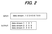
Fig. 2 explains spatial interleaving in a case where s = 1, Ns = 3; -
Fig. 3 shows the switching control configuration of a precoding method in a receiver; -
Fig. 4 is a simulation result example showing error rates versus SNR; -
Fig. 5 is a configuration diagram of the MIMO-OFDM transmission/reception system of a second embodiment; -
Fig. 6 is a configuration diagram of the MIMO-OFDM transmission/reception system of a third embodiment; -
Fig. 7 is a configuration diagram of the MIMO-OFDM transmission/reception system of a fourth embodiment; -
Fig. 8 is a configuration diagram of the MIMO-OFDM transmission/reception system of a fifth embodiment; -
Fig. 9 explains spatial interleaving processing; -
Fig. 10 is a configuration diagram of the MIMO-OFDM transmission/reception system of a sixth embodiment; -
Fig. 11 is a configuration diagram of the MIMO-OFDM transmission/reception system of a seventh embodiment; -
Fig. 12 is a configuration diagram of a MIMO-OFDM communication device in a hybrid STBC spatial multiplexing OFDM system (eighth embodiment); -
Fig. 13 explains STBC encoding processing to map two data streams to four antennas; -
Fig. 14 explains STBC encoding processing to map two data streams to three antennas; -
Fig. 15 explains STBC-IFFT processing; -
Fig. 16 is a configuration diagram of a MIMO-OFDM communication device in a hybrid SFBC spatial multiplexing OFDM system (ninth embodiment); -
Fig. 17 explains SFBC encoding processing to map two data streams to four antennas; -
Fig. 18 explains SFBC encoding processing to map two data streams to three antennas; -
Fig. 19 explains SFBC-IFFT processing; -
Fig. 20 is a configuration diagram of a MIMO-OFDM communication device provided with retransmit functions (tenth embodiment); -
Fig. 21 explains the configuration of a MIMO system; -
Fig. 22 is a configuration diagram of a conventional MIMO-OFDM system; -
Fig. 23 is a configuration diagram of another conventional MIMO-OFDM system; and, -
Fig. 24 explains STBC encoding processing. - Novel weighted Viterbi decoding technology suitable for application in reception processing of a MIMO-OFDM communication system is proposed. The reception device of a MIMO-OFDM communication system calculates the SINR (Signal to Interference Noise Ratio) of a MIMO decoding channel, regards the calculated SINR value as the signal reliability, and uses the SINR as the weighting coefficient of the path metric in Viterbi decoding. By means of this method, the error rate of reception data can be reduced through simple signal processing without performing adaptive modulation control or power control, that is, through simple signal processing using a low-complexity ZF decoding algorithm or MMSE decoding algorithm.
-
Fig. 1 shows the configuration of the MIMO-OFDM communication system of a first embodiment. The transmitting side has Nt transmission antennas, the receiving side has Nr reception antennas, and the number of transmission data streams is Ns, where Ns ≤ min{Nr,Nt}.
On the transmitting side, theFEC encoder 51 employs convolution encoding to perform error detection and correction encoding processing of an input data stream, thepuncture portion 52 performs puncture processing of the encoded data series according to the coding rate, and thespatial interleaver 53 divides the puncture-processed data bit series into a plurality of data streams, which are Ns data streams in the figure. Specifically, thespatial interleaver 53 periodically sends s bit continuous blocks to different data streams in turn. Here, s may be chosen from the following three options.


Here NBPSC is the number of coded bits per subcarrier. For example, in a case where the above 3) is adopted, if data modulation employs BPSK modulation then s=1, if QPSK modulation is used then s=2, and if 16QAM modulation is used then s=4.Fig. 2 explains spatial interleaving when s=1 and Ns=3.
The frequency interleavers 541 to 54Ns perform frequency interleaving in which the positions of the input serial data (subcarrier signal components) are interchanged. The constellation mappers 551 to 55Ns perform constellation mapping of each of the signal components for the number of subcarriers, according to a prescribed data modulation method, for example QPSK modulation. - Then, the
precoder 56 multiples each of the Ns data streams by a prescribed precoding matrix, and converts the Ns data streams into Nt data streams. That is, theprecoder 56 uses a precoding matrix F(k) to map Ns transmission data streams to Nt transmission antennas.
Here k is the subcarrier index, s(k) is an Ns×1 transmission data vector, and x(k) is an Nt×1 transmission antenna data vector.
TheIFFT portions 571 to 57Nt convert the series-input data from theprecoder 56 into parallel data for the number of subcarriers, and then perform IFFT (inverse Fourier transform) of this parallel data, combining the data in discrete time signals (OFDM signals), which are output. The guard interval insertion portions 581 to 58Nt insert guard intervals into the OFDM signals input from the IFFT portions, and the transmission portions (TX) 591 to 59Nt perform DA conversion of the OFDM signals with guard intervals inserted, then convert the frequency of the OFDM signals from baseband to a wireless band, perform high-frequency amplification, and transmit the signals from theantennas 601 to 60Nt.
Signals transmitted from thetransmission antennas 60a to 60Nt pass through fading channels (propagation paths) and are received by thereception antennas 611 to 61Nr of the reception device; the reception circuits (Rx) 621 to 62Nr convert the RF signals received by the antennas into baseband signals, perform AD conversion of the baseband signals into digital signals, and output the signals. The symbol extraction portions 631 to 63Nr delete the guard intervals GI, extract OFDM symbols with FFT timing, and input the signals to theFFT portions 641 to 64Nr. TheFFT portions 641 to 64Nr perform FFT processing for each OFDM symbol extracted, converting the symbols into frequency-domain subcarrier samples.
Thechannel estimation circuit 65 performs channel estimation for each subcarrier using a well-known method, and the codeword determination portion 81 determines the code word corresponding to the optimum precoding matrix F(k) from a code book, and notifies the transmitting-side precoder 56 of the index number. By this means, theprecoder 56 uses the same code book as on the receiving side to determine the precoding matrix F(k), and performs the computation of equation (5). Thechannel estimation portion 65 inputs the channel matrix H(k) for each estimated subcarrier into theMIMO processing portion 66 andSINR calculation portion 72. - Frequency domain signals y(k) output from the
FFT portions 641 to 64Nr can be represented by the following equation.
Here H(k) is the kth subcarrier channel matrix, n(k) represents an Nr×1 noise vector, y(k) represents an Nr×1 reception signal vector, and the signals from each reception antenna are superpositions of transmission signals. y(k), H(k) and F(k) are known from measurements in the receiver. In order to obtain the transmission signals
theMIMO processing portion 66 can use an MLD algorithm, but the degree of complexity becomes enormous. Hence a linear decoder represented by the following equation, with low degree of complexity, is adopted.
Here G(k) is an NsxNr matrix. When using a ZF (Zero Forcing) linear decoder, G(k) is represented by the following equation:
Here (.)+ indicates the pseudo-inverse matrix.
On the other hand, when using an MMSE (Minimum Mean Square Error) linear decoder, G(k) is represented by the equation
where (.)-1 indicates the inverted matrix, and ()' indicates the complex conjugate transpose. Also, No is the noise power received by antennas, εs is the total transmission power of the kth subcarrier, and INs is the NsxNs identity matrix. - The
SINR calculation portion 72 uses the channel matrix H(k) and precoding matrix F(k) to calculate the SINRi(k) and input the result to thedecoding portion 71, as described below.
The constellation demappers 671 to 67Ns, frequency deinterleavers 681 to 68Ns,spatial deinterleaver 69,depuncture portion 70, and decodingportion 71 perform, in the order opposite that on the transmitting side, demapping, frequency deinterleaving, spatial deinterleaving, and decoding processing (weighted error correcting/decoding processing) of each of the data streams
separated using equation (7). The decodingportion 71 takes the input SINR to be the signal reliability, and imparts weighting by multiplying the Viterbi decoding path metric by this SINR, to execute weighted error correcting/decoding processing. - Methods to determine the precoding matrix F(k) include (1) a limited feedback precoding method, (2) eigen-mode transfer precoding method, and (3) spatial multiplexing precoding method. If the channel H(k) is unknown, the
precoder 56 employs a spatial multiplexing precoding method, using the identity matrix as the precoding matrix F(k) to compute equation (5) and perform space-division multiplexed transfer. If the channels H(k) are known on the transmitting side and on the receiving side, theprecoder 56 adopts an eigen-mode transfer precoding method, performs singular value decomposition (SVD) of the channel matrix H(k), takes the decomposed right singular matrix to be the precoding matrix F(k), and performs the computation of equation (5). If an index identifying the precoding matrix F(k) based on the channel H(k) is determined and is fed back from the receiving side, then a limited feedback precoding method is adopted, and theprecoder 56 determines the precoding matrix F(k) according to the index and performs the computation of equation (5). Below, each of these systems is described in detail. - The principle of the limited feedback precoding method is explained. A code book is created in advance, based on a number of data streams Ns, number of transmission channels Nt, and number of feedback bits (L), and it is assumed that the transmitter and receiver have the same code book.
The codeword determination portion 81 of the receiver uses the channel H(k) to select the optimum code word from the code book, and uses a limited feedback channel to feed back the index of the code word to the transmitter. The transmitter uses the fed-back index to select the precoding matrix F(k) from the code book, and multiplies the transmission data streams by this matrix F(k) to perform precoding. The code book is a set of predetermined unitary matrices, and a code word defines one unitary matrix in the code book. If U is a unitary matrix, then the equation
is satisfied. The limited feedback precoding method is described in the paper "Limited Feedback Unitary Precoding for Spatial Multiplexing Systems" by David J. Love and Robert W. Heath Jr., IEEE Transactions on Information Theory, Vol. 51, No. 8, August 2005, pp. 2967-2976. - The following is the detailed order of operation of the limited feedback precoding method.
- (1) First, the code
word determination portion 81 of the receiver selects a code word. This code word selection is performed as follows. In thechannel estimation portion 65, channel estimation is performed, to determine a channel H(k). Then, the codeword determination portion 81 uses the channel H(k) thus determined to select the optimum code word, according to the following criteria (1-1) through (1-3).
(1-1) MMSE (minimum mean square error) selection criterion
The MSE (mean square error) of the receiver can be represented as follows, if H(k) and F(k) are known.
The code word is selected from the code book, based on the following equations, so as to minimize MSE Trace (tr) or Determinant (det):

Here Trace (tr) is the sum of the diagonal elements of the matrix.
In place of the above equations, the code word can be determined using the following simplified equations.

- The code
word determination portion 81 can select a code word from the code book using the following equation, such that the capacity, or in other words, the amount of information communicated per prescribed time, is maximized.
Or, the following simplified equation can also be used.
It should be noted that in principle, from equations (12b) and (14), the maximum-capacity selection criterion and the minimum Det(MSE) criterion are equivalent. - The code
word determination portion 81 selects a code word from the code book using the following equation, so as to maximize the minimum singular value.
Equation (15) means that the matrix H(k)Fj(k) is determined for each of the candidates Fj(k) for code words in the code book, singular value decomposition of the matrix {H(k)Fj(k)} is performed to determine the minimum singular value λmin, and the candidate Fj(k) resulting in the largest minimum singular value among all the minimum singular values is used.
In the above, a case was explained in which a code word is determined using singular value decomposition; but the code word can be similarly determined using eigenvalue decomposition as well. - (2) When the code word is determined, the code
word determination portion 81 feeds back the index of the code word to theprecoder 56 of the transmitter. That is, the receiver transfers to the transmitter, via a limited feedback channel, the index (L bits) of the selected optimum code word. -
- (3) The
precoder 56 of the transmitter, upon receiving the index, references the internal code book and selects the matrix corresponding to the received index. Then, theprecoder 56 uses this selected matrix as a MIMO precoding matrix. - (4) The
MIMO processing portion 66 of the receiver uses a ZF (Zero Forcing) linear decoder or an MMSE (Minimum Mean Square Error) linear decoder to separate the transmission signals,
in parallel with the above code word selection processing. -
- (5) Or, the
SINR calculation portion 72 calculates the SINR to be used as weighting for the path metric in Viterbi decoding processing. - When a ZF decoder (ZF decoding algorithm) is used for transmission signal separation, the
SINR calculation portion 72 calculates the SINR values for each subcarrier using the following equation and inputs the calculation results to thedecoding portion 71.
Here i is an index for data streams. Also, [ · ]i,i is the element in the ith row and ith column of a matrix.
The decodingportion 71 weights the Viterbi path metric by the calculated SINR values as indicated by the following equation.
Viterbi path metric:
Here i is an index for data streams, and n is an index for demapped bits. For example, in the case of 16QAM modulation, demapped bits are the four bits b1 to b4, so that n=1 means b1, n=2 means b2, n=3 means b3 and n-4 means b4. Moreover,
is a soft decision value, and
is a reference value
In this way, by weighting the Viterbi path metric using SINR values, increases in noise due to the ZF decoding algorithm are reduced, and performance can be improved. - The above was a case when a ZF decoder is used; when an MMSE decoder (MMSE decoding algorithm) is used in transmission signal separation, the
SINR calculation portion 72 uses the following equation to calculate the SINR for each subcarrier, and inputs the results to thedecoding portion 71.
The decodingportion 71 uses the calculated SINR values to weight the Viterbi path metric according to the following equation.
Viterbi path metric:
By using the SINR values to weight the Viterbi path metric as described above, increases in noise due to the MMSE decoding algorithm can be reduced, and performance can be improved.
The values calculated using equation (16) for
can be used to weight MMSE decoded signals. Conversely, ZF-decoded signals can be weighted using the value of
calculated in equation (18).
In order to reduce the degree of complexity, when the SINR is lower than a threshold value the SINR can be set to 0, and when the SINR is equal to or greater than the threshold value, the SINR can be set to 1. - Substitution of equation (6) into equation (7) yields the following equation.

For the linear decoders ZF and MMSE, the second term G(k)n(k) in the above equation is a noise increase. When G(k)n(k) is large, the noise in the decoded signal is increased markedly, and the performance of the linear decoder is degraded. Particularly in the case of a frequency-selective MIMO channel, this problem is serious. In this invention, by weighting the Viterbi path metric with the SINR value, this noise increase can be reduced. That is, in this invention the SINR is calculated for each of the data streams and each subcarrier, and the SINR value is adopted as the reliability of demodulated signals to perform weighted Viterbi decoding, as in equations (17) and (19). As a result, when the SINR is small (when the noise increase is large), the contribution of the Viterbi path metric is reduced, and conversely, when the SINR is large (when the noise increase is small), the contribution of the Viterbi path metric is increased, so that as a result the performance can be improved. - The eigen-mode transfer precoding method can be adopted when the channel state information CSI (channels H(k)) at the transmitter and receiver are known. In the eigen-mode transfer precoding method, the channel matrix H(k) is subjected to singular value decomposition (SVD), and the matrix obtained from this analysis is used as the precoding matrix, to construct a high-performance system.
That is, for a subcarrier k, the channel matrix H(k) is an NrxNt matrix. Singular value decomposition of H(k) can be represented as follows.

U(k) in equation (21a) is the left singular matrix, and V(k) is called the right singular matrix. D(k) is a diagonal matrix, and has the diagonal elements indicated in equation (21b). λ1(k), ... , λm(k) are proportional to the eigen-mode gain, and are arranged in order of magnitude, with the first eigen-mode λ1(k) having the largest gain, and the mth eigen-mode λm(k) having the smallest gain. That is, λ1(k) > λ2(k) > ... > λm(k). m is the rank of the channel H(k). The optimal precoding matrix is the Ns columns on the left side of the right singular matrix V(k). - From the above analysis, in an ideal case, that is, when the channel state information CSI (channel H(k)) is known at the transmitter and the receiver, and moreover the two completely coincide, the eigenvalues λi(k) are taken to be the weighting of the path metric in Viterbi decoding, as indicated by the following equation. That is, the decoding
portion 71 takes the above eigenvalues λi(k) to be the path metric weight, which is multiplied by the path metric to perform decoding, and by this means noise increases due to the ZF decoding algorithm and MMSE decoding algorithm can be reduced, and performance can be improved.
When realizing the eigen-mode transfer precoding method, there exist numerous problems, for example relating to channel quantization errors and changes with time in the channel, and in many cases the realization of the eigen-mode transfer precoding method is difficult. In such cases, it is more practical to use the limited feedback precoding method to determine the SINR for use in weighting the path metric. - The spatial multiplexing precoding method is a method in which, when H(k) is unknown on the transmitting side, the identity matrix is used as the precoding matrix F(k). That is, in the case of the spatial multiplexing precoding method, the precoding matrix F(k) is the identity matrix. Consequently the
SINR calculation portion 72 can simply calculate the SINR using the following equation.

Here equation (23a) is for the case in which the ZF decoding algorithm is adopted, and equation (23b) is for the case in which the MMSE decoding algorithm is used.
The decodingportion 71 uses the SINR calculated as above as the path metric weight, multiplying by the path metric to perform decoding, that is, performing decoding according to equation (17) or equation (19), and so the noise increase due to the ZF decoding algorithm or to the MMSE decoding algorithm can be reduced, and performance can be improved. - Depending on the channel conditions and the capabilities of the communication device, the precoding method can be switched between the limited feedback precoding method, eigen-mode transfer precoding method, and spatial multiplexing precoding method, to perform OFDM-MIMO communication.
Specifically, the channel condition number is calculated for each subcarrier using equation (24), the average value thereof is determined as the channel average condition number, and when the channel average condition number is satisfactory, that is, when the channel average condition number is equal to or less than a certain threshold, the spatial multiplexing precoding method is used, but when the channel average condition number is poor, that is, when the average channel condition number exceeds the threshold, the eigen-mode transfer precoding method or the limited feedback precoding method is used, depending on the capabilities of the communication device. - The channel condition number can be calculated using the following equation.

In the above equation, the numerator is the maximum value of diagonal elements in the diagonal matrix obtained by singular value decomposition of the channel matrix H(k) (the maximum singular value), and the denominator is the minimum value of the diagonal elements (the minimum singular value). The smaller the channel condition number, the more uniform are the channels (propagation characteristics) for each propagation path, and the better the reception state can be. In order to secure reliable communication, in some cases it is also possible to reduce the number of data streams. - In the above, a case was explained in which the channel condition number is calculated by means of singular value decomposition; but the channel condition number can similarly be calculated by eigenvalue decomposition.
Further, the above was a case of switching between the limited feedback precoding method, eigen-mode transfer precoding method, and spatial multiplexing precoding method; but switching can also be between the spatial multiplexing precoding method and the limited feedback precoding method based on the channel average condition number, without using the eigen-mode transfer precoding method.
Further, the precoder can use the spatial multiplexing precoding method when the channel H(k) is an unknown initial value, and switching control can be performed so as to use the limited feedback precoding method when the precoding matrix is determined based on the channel H(k).
Fig. 3 shows the configuration for switching control between precoding methods in a receiver; 200a is a reception portion, and 200b is a transmission portion. In thereception portion 200a are provided, in addition to achannel estimation portion 65, codeword determination portion 81, andcode book 82, a channel conditionnumber computation portion 83 and precodingmethod determination portion 84. The channel conditionnumber computation portion 83 computes the channel average condition number based on equation (24), and the precoding method determination portion determines, based on the channel average condition number, whether to use the spatial multiplexing precoding method or the limited feedback precoding method, and transmits precoding command data PC to theprecoder 56 of the transmitter via thetransmission portion 200b. Based on the indicated precoding method, theprecoder 56 determines the precoding matrix and performs the computation of equation (5). - The
MIMO processing portion 66 can use the ZF decoding algorithm or the MMSE decoding algorithm as the decoding algorithm, but depending on the modulation method, the ZF decoding algorithm and the MMSE decoding algorithm can be used selectively. For example, in the case of BPSK and QPSK, the MMSE decoding algorithm may be used, while for 16QAM and 64QAM the ZF decoding algorithm is used. The reason for this is as follows.
The MMSE decoding algorithm is robust with respect to noise, whereas the ZF decoding algorithm is not as robust with respect to noise as the MMSE decoding algorithm. BPSK and QPSK are modulation methods used when noise is intense, and so when using the BPSK or QPSK modulation method, the MMSE decoding algorithm is used. 16QAM and 64QAM are modulation methods used when the reception quality is good, and so when using the 16QAM or 64QAM modulation method, the ZF decoding algorithm is used. -
Fig. 4 shows an example of simulation results indicating the error rate versus the signal-to-noise ratio SNR; the vertical axis shows the packet error rate PER, and the horizontal axis indicates the signal-to-noise ratio (SNR). (A) is the simulation result for a ZF decoder, and (B) is the simulation result for an MMSE decoder; in these cases the modulation method and coding rate are 16QAM and 1/2. In the case of the spatial multiplexing precoding method, the number of transmission antennas is 2, and the number of reception antennas is 2. In the cases of the eigen-mode transfer precoding method and the limited feedback precoding (LFP) method, the number of transmission data streams, number of transmission antennas, and number of reception antennas are respectively 2, 4, and 2.
SP1 and SP2 are are characteristics of spatial multiplexing precoding methods; SP1 is for a case without weighting, and SP2 is for a case with weighting. LFP1 and LFP2 are limited feedback precoding method characteristics; LFP1 is without weighting, and LFP2 is with weighting. MP1 and MP2 are eigen-mode transfer precoding method characteristics; MP1 is without weighting, and MP2 is with weighting.
As is clear from (A) and (B) ofFig.4 , when performing MIMO processing based on the ZF decoding algorithm or MMSE decoding algorithm, in either case the characteristics are confirmed to be improved for the precoding method when weighting is performed.
Of the three precoding method, the performance is best for the eigen-mode transfer precoding method, followed by the performance of the limited feedback precoding method, with the performance of the spatial multiplexing precoding method in third place. - In the above, cases of use in MIMO (Multiple-Input, Multiple-Output) systems were explained; however, this invention can also be applied to MISO (Multiple-Input, Single-Output) and SIMO (Single-Input, Multiple-Output) systems.
In the case of MISO or SIMO, the SINR can be calculated using the following equation.
Hence thedecoding portion 71 represents the path metric in Viterbi decoding using the following equation to perform decoding processing.
In the above equation, i is the index of the transmission antenna (for MISO) or of the reception antenna (for SIMO).
This invention can also be applied to SISO (Single-Input, Single-Output) systems. In the case of SISO, the SINR can be calculated using the following equation.
Hence thedecoding portion 71 represents the path metric in Viterbi decoding using the following equation to perform decoding processing.
-
Fig. 5 shows the configuration of the MIMO-OFDM transmission/reception system of a second embodiment; portions which are the same as in the first embodiment ofFig. 1 are assigned the same symbols. A difference with the first embodiment is the fact that frequency interleaving is performed before spatial interleaving.
The transmitting side comprises one each of anFEC encoder 51,puncture portion 52, andfrequency interleaver 54. In order to utilize spatial diversity, thespatial interleaver 53 divides the frequency-interleaved data bits into Ns data streams, which are input to the constellation mappers 551 to 55Ns. The constellation mappers 551 to 55Ns perform constellation mapping, and theprecoder 56 performs precoding according to a prescribed method. The subsequent procedure is the same as in the first embodiment.
On the receiving side, theMIMO processing portion 66 separates the data streams according to the MMSE decoding algorithm or the ZF decoding algorithm, and thereafter, constellation demapping, spatial deinterleaving, frequency deinterleaving, depuncture processing, and decoding processing (weighted error-correcting/decoding processing) are performed, in the order opposite that on the transmitting side.
In the second embodiment, the circuit scale of thefrequency interleaver 54 can be reduced, and moreover spatial diversity can be utilized. -
Fig. 6 shows the configuration of the MIMO-OFDM transmission/reception system of a third embodiment; portions which are the same as in the first embodiment ofFig. 1 are assigned the same symbols. A difference with the first embodiment is the fact that before performing spatial interleaving, frequency interleaving and constellation mapping are performed.
The transmitting side comprises one each of anFEC encoder 51,puncture portion 52,frequency interleaver 54, andconstellation mapper 55. In order to utilize spatial diversity, thespatial interleaver 53 divides the constellation-mapped data bits into Ns data streams, which are input to theprecoder 56, and theprecoder 56 performs precoding according to a prescribed method. The subsequent procedure is the same as in the first embodiment.
On the receiving side, theMIMO processing portion 66 separates the data streams according to the MMSE decoding algorithm or the ZF decoding algorithm, and thereafter, spatial deinterleaving, constellation demapping, frequency deinterleaving, depuncture processing, and decoding processing (weighted error-correcting/decoding processing) are performed, in the order opposite that on the transmitting side.
In the third embodiment, the circuit scale of thefrequency interleaver 54 andconstellation mapper 55 can be reduced, and moreover spatial diversity can be utilized. -
Fig. 7 shows the configuration of the MIMO-OFDM transmission/reception system of a fourth embodiment; portions which are the same as in the first embodiment ofFig. 1 are assigned the same symbols. A difference with the first embodiment is the fact that Ns transmission data streams are input, there are provided, corresponding to each of the transmission data streams, FEC encoders 511 to 51Ns,puncture portions 521 to 52Ns, frequency interleavers 541 to 54Ns, andconstellation mappers 551 to 55Ns, and there exists no spatial interleaver.
Theprecoder 56 performs precoding, according to a prescribed method, of constellation-mapped signals.
Subsequent processing is the same as in the first embodiment.
On the receiving side, theMIMO processing portion 66 separates data streams according to the MMSE decoding algorithm or the ZF decoding algorithm, and thereafter, for each of the separated data streams, constellation demapping, frequency deinterleaving, depuncture processing, and decoding processing (weighted error-correcting/decoding processing) are performed, in the order opposite that on the transmitting side.
In the fourth embodiment, each of the data streams can be processed in parallel, so that the circuit operating frequency can be lowered. However, spatial diversity cannot be utilized, so that there is some degradation of performance, particularly when using the eigen-mode transfer precoding method. -
Fig. 8 shows the configuration of the MIMO-OFDM transmission/reception system of a fifth embodiment; portions which are the same as in the fourth embodiment ofFig. 7 are assigned the same symbols. A difference with the fourth embodiment is the fact that aspatial interleaver 53 is provided between thepuncture portions 521 to 52Ns and thefrequency interleavers 541 to 54Ns.
In order to utilize spatial diversity, thespatial interleaver 53 rearranges the dta streams after puncturing of each of the data streams. The rearranged data streams are then each subjected to frequency interleaving and constellation mapping, and are input to theprecoder 56. Theprecoder 56 performs precoding processing, according to a prescribed method, of the constellation-mapped signals. Subsequent processing is the same as in the first embodiment.
On the receiving side, theMIMO processing portion 66 separates data streams according to the MMSE decoding algorithm or the ZF decoding algorithm, and thereafter, for each of the separated data streams, constellation demapping, frequency deinterleaving, spatial deinterleaving, depuncture processing, and decoding processing (weighted error-correcting/decoding processing) are performed, in the order opposite that on the transmitting side.
Fig. 9 explains spatial interleaving; in this example, there are three input data streams and three output data streams. Thespatial interleaver 53 distributes the first three data items of the first input data stream to each of the three output data streams, then distributes the first three data items of the second data stream to the three output data streams, and then distributes the first three data items of the third data stream to the three output data streams; thereafter, similar rearrangement is performed to execute spatial interleaving.
In the fifth embodiment, the circuit scale increases slightly compared with the fourth embodiment, but because the data streams can be processed in parallel, the circuit operating frequency can be lowered, and moreover spatial diversity can be utilized. -
Fig. 10 shows the configuration of the MIMO-OFDM transmission/reception system of a sixth embodiment; portions which are the same as in the fourth embodiment ofFig. 7 are assigned the same symbols. A difference with the fourth embodiment is the fact that aspatial interleaver 53 is provided between thefrequency interleavers 541 to 54Ns and the constellation mappers 551 to 55Ns.
In order to utilize spatial diversity, thespatial interleaver 53 rearranges the data streams after performing frequency interleaving of the data streams. Then, constellation mapping is performed for each of the rearranged data streams, and the results are input to theprecoder 56. Theprecoder 56 performs precoding processing of the constellation-mapped signals according to a prescribed method. The subsequent procedure is the same as in the first embodiment.
On the receiving side, theMIMO processing portion 66 separates data streams according to the MMSE decoding algorithm or ZF decoding algorithm, and thereafter, constellation demapping, spatial deinterleaving, frequency deinterleaving, depuncture processing, and decoding processing (weighted error-correction/decoding processing) of each of the separated data streams are performed, in the order opposite that on the transmitting side.
As a result of the sixth embodiment, the circuit scale is increased slightly compared with the fourth embodiment, but because the data streams can be rearranged, the circuit operating frequency can be lowered, and moreover spatial diversity can be utilized. -
Fig. 11 shows the configuration of the MIMO-OFDM transmission/reception system of a seventh embodiment; portions which are the same as in the fourth embodiment ofFig.7 are assigned the same symbols. A difference with the fourth embodiment is the fact that aspatial interleaver 53 is provided between the constellation mappers 551 to 55Ns and theprecoder 56.
In order to utilize spatial diversity, thespatial interleaver 53 rearranges the data streams after performing constellation mapping of the data streams, and the results are input to theprecoder 56. Theprecoder 56 performs precoding processing of the constellation-mapped signals according to a prescribed method. The subsequent procedure is the same as in the first embodiment.
On the receiving side, theMIMO processing portion 66 separates data streams according to the MMSE decoding algorithm or ZF decoding algorithm, and thereafter, spatial deinterleaving, constellation demapping, frequency deinterleaving, depuncture processing, and decoding processing (weighted error-correction/decoding processing) of each of the separated data streams are performed, in the order opposite that on the transmitting side.
As a result of the seventh embodiment, the circuit scale is increased slightly compared with the fourth embodiment, but because the data streams can be rearranged, the circuit operating frequency can be lowered, and moreover spatial diversity can be utilized. -
Fig. 12 is a configuration diagram of a MIMO-OFDM communication device in a hybrid STBC spatial multiplexing OFDM system, having Nt transmission antennas on the transmitting side and Nr reception antennas on the receiving side. If the number of transmission data streams is Ns, then Ns ≤ min[Nr, Nt].
On the transmitting side, theFEC encoder 151 performs encoding processing for error detection and correction of the input data stream using a convolution code, thepuncture portion 152 performs puncture processing of the encoded data series according to the coding rate, and thespatial interleaver 153 divides the puncture-processed data bit series into a plurality of data streams, which inFig. 12 are Ns data streams. Specifically, thespatial interleaver 153 sends continuous blocks of s bits periodically to each data stream in turn(seeFig. 2 ).
The frequency interleavers 1541 to 154Ns perform frequency interleaving in which the positions of the input serial data (subcarrier signal components) are interchanged. The constellation mappers 1551 to 155Ns perform constellation mapping of each of the signal components for the number of subcarriers according to a prescribed data modulation method, for example, QPSK modulation. - Next, the STBC encoders 1561 to 156Ns of the
STBC portion 156 perform STBC encoding processing of the input serial data, convert the Ns data series into Nt data series, and map the result to Nt transmission antennas.Fig. 13 is an example of mapping two data streams to four antennas, and similarly,Fig. 14 is an example of mapping two data streams to three antennas. In the example ofFig. 13 , the continuous two-symbol data with period T [s11,s12] input from the constellation mapper 1551 is converted into two series of symbol data [s11, -s12*], [s12,s11*] in theSTBC encoder 1561, which are mapped to the transmission antennas 1601, 1602. And, the continuous two-symbol data with period T [s21,s22] input from the constellation mapper 1552 is converted into two series of symbol data [s21, -s22*], [s22,s21*] in theSTBC encoder 1562, which are mapped to the transmission antennas 1603, 1604. In the example ofFig. 14 , the continuous two-symbol data with period T [s11,s12] input from the constellation mapper 1551 is converted into two series of symbol data [s11, -s12*], [s12,s11*] in theSTBC encoder 1561, which are mapped to the transmission antennas 1601, 1602, but the continuous two-symbol data with period T [s21,s22] input from the constellation mapper 1552 is mapped to the transmission antenna 1603 as-is, without performing STBC encoding processing. - The IFFT (Inverse Fast Fourier Transform)
portions 1571 to 157Nt convert the series-input data from theSTBC portion 156 into parallel data for the number of subcarriers, and then perform IFFT (inverse Fourier transform) of this parallel data, combining the data in discrete time signals (OFDM signals), which are output.Fig. 15 explains IFFT processing. TheSTBC encoder 1561 performs the above STBC encoding processing of the continuous two OFDM symbols input from the constellation mapper 1551, as shown in (A) ofFig. 15 , and generates two respective series. The serial/parallel conversion portion 157SP of theIFFT portion 1571 converts the serial STBC encoded data input from theSTBC encoder 1561 into k parallel data at time t0 and k parallel data at time t1 as shown in (B) ofFig. 15 , and theIFFT processing portion 157IFFT performs IFFT (inverse Fourier transform) processing in order on each of the parallel data series, combining the data for output as discrete time signals (OFDM signals). TheIFFT portion 1572 performs processing similar to that of theIFFT portion 1571. And, theSTBC encoder 1562 andIFFT portions STBC encoder 1561 andIFFT portions
Returning toFig. 12 , the guard interval insertion portions 1581 to 158Nt insert guard intervals into the OFDM signals input from the IFFT portions, the transmission portion (TX) 1591 to 159Nt perform DA conversion of the OFDM signals with guard intervals inserted, and the OFDM signal frequency is converted from baseband to a wireless range, signals are high-frequency amplified, and transmitted from the antennas 1601 to 160Nt. - Signals transmitted from the transmission antennas 1601 to 160Nt pass through fading channels (transmission paths), and are received by the reception antennas 1611 to 161Nr of the reception device; the receiving circuits (Rx) 1621 to 162Nr convert the RF signals received by the antennas into baseband signals, and perform AD conversion of the baseband signals into digital signals, which are output. The symbol extraction portions 1631 to 163Nr delete the guard intervals GI, extract OFDM symbols with FFT timing, and input the signals to the FFT portions 1641 to 164Nr. The FFT portions 1641 to 164Nr perform FFT processing for each OFDM symbol extracted, converting the symbols into frequency-domain subcarrier samples.
In the case of the STBC encoding processing of (A) ofFig. 13 , the reception signals y11, y12, y21, y22 of the signals s11, s12, s21, s22 transmitted by the subcarriers f1 can be expressed by the following equation.
In equation (29), hi,j is the channel response at frequency f1 from the jth transmitting channel to the ith reception antenna shown in (B) ofFig. 13 . si,j represents the jth symbol in the ith data stream. yi,j represents the jth received symbol at the ith reception antenna. wi,j represents the jth received symbol AWGN noise at the ith reception antenna.
Similarly, the received signals y13, y14, y23, y24 of the signals s13, s14, s23, s24 transmitted by the subcarrier f2 can be represented by the following equation. hi,j' is the channel response at frequency f2 of the ith reception antenna from the jth transmission antenna.
From the above, the received signals for each subcarrier component can be represented by equations similar to equation (29).
The following equation obtains from a simple conversion from equation (29). This conversion is conversion of the two-row, two-column matrix on the left side in equation (29) into a four-row, one-column vector. The following equations (31) to (40) are general expressions without addition of a subcarrier index k, but are equations which obtain for each subcarrier.
where


Here (.)T indicates the matrix transpose. Also, the channel correlation profile of He has the following characteristic.
In this equation,

Similarly, by a simple conversion fromFig. 14 , the following equations

are obtained. ye and we are respectively the same as in equation (34) and equation (35). The above is for cases in which Ns = 2, Nt = 3 and Ns = 2, but clearly application to two or more transmission data streams and to three or more transmission antennas is possible. - In the receiver, ye and He are known, and so the
MIMO processing portion 166 can use maximum likelihood (ML) to determine transmission signals. However, due to the vast increase in complexity, a linear decoder of reduced complexity is adopted. In the linear decoder, the following equation obtains.
Here Ge is a 2Nsx2Nr matrix. When using a ZF (Zero Forcing) linear decoder, Ge is given by the following equation.
Here (.)+ represents the pseudo-inverse of a matrix, and (.)' represents the complex conjugate transpose.
The inverse matrix in equation (39) can be represented by the following equation.
As shown in equation (39a), in actuality there is no need to calculate the inverse matrix, and the complexity can be reduced.
On the other hand, when a MMSE (Minimum Mean Square Error) linear decoder is used, Ge is given by the following equation.
Here (.)-1 represents matrix inversion, and ()' represents the complex conjugate transpose. Also, N0 is the antenna received noise power, εs is the total transmission power of the kth subcarrier, and I2Ns is a 2Nsx2Ns identity matrix.
Similarly to equation (39a), the inverse matrix in equation (40) can be represented as follows.
As indicated in equation (40a), in actuality there is no need to calculated the inverse matrix, and the complexity can be reduced. - The
SINR calculation portion 172 uses the channel matrix He, described below, to calculate SINRj(k) and input the result to thedecoding portion 171. The constellation demappers 1671 to 167Ns,frequency deinterleavers 1681 to 168Ns,spatial deinterleaver 169,depuncture portion 170, anddecoding portion 171 perform demapping processing, frequency deinterleave processing, spatial deinterleave processing, and decoding processing (weighted error correction/decoding processing), in the reverse order of the transmitting-side processing, of each of the data streams
,which are separated by theMIMO processing portion 166, according to equations (38) and (39), or according to equations (38) and (40).
Thedecoding portion 171 regards the SINR input from theSINR calculation portion 172 as the signal reliability, performs weighted multiplication of this SINR with the Viterbi decoding path metric, and executes weighted error correction/decoding processing. - (1) SINR calculation and Viterbi decoding when using a ZF decoder
When using a ZF decoder (ZF decoding algorithm) for transmission signal separation, theSINR calculation portion 172 calculates the SINR for each subcarrier k using the following equations, and inputs the results to thedecoding portion 171.

Here j is the index of the layers of the converted channel. "Layer index" means the index of the column in the square matrix in equation (33) or equation (37). That is, columns in the above square matrices are defined as layers. Also, [ · ]j,j is the element in the jth row and jth column of the matrix. Thedecoding portion 171 multiplies the Viterbi path metric by the SINR as shown in the following equation, thereby weighting is realized.
Here n is the demapped bit index. For example, in the case of 16QAM modulation, demapped bits are four bits b1 to b4, so that if n = 1 then b1 is meant, and n = 2 means b2. i is the data stream index. Also,
is a soft decision value, and
is a reference value. By weighting the Viterbi path metric with the SINR as described above, the increase in noise due to the ZF decoding algorithm is reduced, and performance can be improved. - When using an MMSE decoder (MMSE decoding algorithm) for transmission signal separation, the
SINR calculation portion 172 calculates the SINR for each subcarrier k using the following equations, and inputs the results to thedecoding portion 171.

Thedecoding portion 171 multiplies the Viterbi path metric by the SINR as shown in the following equation.
By weighting the Viterbi path metric by the SINR as above, the noise increase due to the MMSE decoding algorithm is reduced, and performance can be improved.
To weight the MMSE-decoded signal,
calculated using equation (41) can be used. Conversely, for a ZF-decoded signal,
calculated using equation (44) can be used as a weighting.
Further, in order to reduce complexity, when the SINR is equal to or less than a threshold value, the SINR may be set equal to 0, and when the SINR is equal to or above a certain threshold value, the SINR may be set equal to 1.
When a linear decoder ZF and linear decoder MMSE are used, noise is increased, but in this invention, by weighting the Viterbi path metric by the SINR, this noise increase can be reduced. That is, in this invention the SINR is calculated for each of the converted channel layers and each subcarrier, this SINR is adopted as the reliability of the demodulated signal, and weighted Viterbi decoding is performed as indicated by equations (43) and (46). By this means, when the SINR is small (when the noise increase is large), the contribution of the Viterbi path metric is reduced, and conversely, when the SINR is large (when the noise increase is small), the contribution of the Viterbi path metric is increased, so that as a result the performance can be improved. -
Fig. 16 is a configuration diagram of the MIMO-OFDM communication device in a hybrid SFBC spatial multiplexing OFDM system; portions which are the same as in the eighth embodiment ofFig. 12 are assigned the same symbols. A difference in the provision of a SFBC (Space Frequency Block Coding)portion 181 in place of theSTBC portion 156.
The SFBC encoders 1811 to 181Ns of theSFBC portion 181 perform SFBC encoding processing of input serial data, convert the Ns data series into Nt data series, and map the result to Nt transmission antennas.Fig. 17 is an example of mapping of two data streams to four antennas, and similarly,Fig. 18 is an example of mapping of two data streams to three antennas. In the example ofFig. 17 , the continuous two-subcarrier data [s11,s12] input from the constellation mapper 1551 is converted into the symbol data series [s11,s12], [-s12*,s11*] of the subcarriers [f1,f2] in theSFBC encoder 1811, and is mapped to the transmission antennas 1601, 1602. And, the continuous two-subcarrier data [s21,s22] input from the constellation mapper 1552 is converted into the symbol data series [s21,s22], [-s22*,s21*] of the subcarriers [f1,f2] in theSFBC encoder 1812, and is mapped to the transmission antennas 1603, 1604. In the example ofFig. 18 , the continuous two-subcarrier data [s11,s12] input from the constellation mapper 1551 is converted into the symbol data series [s11,s12], [-s12*,s11*] of the subcarriers [f1,f2] in theSFBC encoder 1811, and is mapped to the transmission antennas 1601, 1602, but the continuous two-subcarrier data [s21,s22] input from the constellation mapper 1552 is mapped as-is to the transmission antenna 1603, without performing SFBC encoding processing.
TheIFFT portions 1571 to 157Nt convert the serially input data from theSFBC portion 181 into parallel data series for the number of subcarriers, and then perform IFFT (inverse Fourier transform) processing of the parallel data to combine the data into discrete time signals (OFDM signals), which are output.Fig. 19 explains the IFFT processing. TheSFBC encoder 1811 performs the above SFBC encoding processing of the continuous 2 OFDM symbols input from the constellation mapper 1551, and generates two series each of subcarrier fi, fi+1 (i=1,3,....k-1) components at times t0 and t1 as shown in (A) ofFig. 19 . The serial/parallel conversion portion 157SP of theIFFT portion 1571 converts serial SFBC-encoded data input from theSFBC encoder 1811 into k parallel data series at times t0 and t1, as shown in (B) ofFig. 19 , theIFFT processing portion 157IFFT performs IFFT (inverse Fourier transform) processing of the parallel data and combines the data into discrete time signals (OFDM signals), which are output. TheIFFT portion 1572 also performs processing similar to that of theIFFT portion 1571. And, theSFBC encoder 1812 and theIFFT portions SFBC encoder 1811 and theIFFT portions -
Fig. 20 is a configuration diagram of a MIMO-OFDM communication device provided with retransmit functions; portions which are the same as in the eighth embodiment ofFig. 12 are assigned the same symbols. A difference is the provision of anerror detection portion 191, transmissionantenna decision portion 192,transmission portion 193 which transmits ACK/NACK/transmission antenna information, transmission antennaswitching control portion 194, and transmissionantenna switching portion 195.
When the received data comprises errors, the reception device requests data retransmission by the transmission device, and the transmission device performs retransmission of data in response to the retransmission request. In this case, if the same antenna as used the previous time is used for retransmission, there is a strong possibility of occurrence of the same errors. That is, when performing retransmission control in a MIMO system, if the same antenna is used to transmit the retransmission data, then an antenna with a poor transmission state continues to be used, so that the improvement in error rate through retransmission is small, and the advantage of retransmission control is not obtained. In particular, this problem is serious when changes in fading and multipath are slow compared with the retransmission interval (round-trip time). Hence the transmission device in the tenth embodiment performs retransmission of data with the combination of the antennas retransmitting each data item varied, so as to reduce the error rate in retransmission. When there are errors in re-received data, the reception device combines the data with the previously received data to perform decoding.
InFig. 20 , theerror detection portion 191 checks whether errors exist in the decoding results, and if errors exist, the transmissionantenna decision portion 192 decides on the optimum combination of retransmission data and transmission antennas according to antenna interchange rearrangement criteria, described below, and thetransmission portion 193 sends an error present/absent signal (ACK/NACK) and, when errors are present, transmission antenna combination information to the transmission device. The transmissionantenna control portion 194 controls thetransmission antenna portion 195 based on transmission antenna combination information sent from the reception device, and allocates STBC data series output from theSTBC portion 156 to prescribed antennas.
In the case of four transmission antennas inFig. 13 , there are the following six combinations in all of antenna arrangement patterns.
[(1,2)(3,4)], [(1,2)(4,3)], [(1,3)(2,4)], [(1,3)(4,2)], [(1,4)(2,3)], [(1,4)(3,2)]
Hence as combination information, three bits are necessary as feedback bits for each subcarrier. In the case of three transmission antennas inFig. 14 , there are the following three combinations in all of antenna arrangement patterns.
[1,2,3], [1,3,2], [3,1,2]
Hence as combination information, two bits are necessary as feedback bits for each subcarrier. - Below, antenna rearrangement selection criteria, used to decide the optimum combination of transmission antennas, are explained.
- The reception device selects the optimum combination from among all combinations of transmission data and of antennas transmitting transmission data, so as to maximize capacity. That is, the antenna combination is selected so as to satisfy the following equation.

Hs is the channel matrix corresponding to the combination of the transmission data and the antennas transmitting the transmission data, H is the set of channel matrices converted according to all combinations, and det is the matrix determinant. The capacity is for example the throughput (data transmission quantity per unit time). - The reception device selects the optimum combination from among all the combinations of the transmission data and antennas to transmit the transmission data, so as to maximize the minimum singular value (equivalent to maximizing the minimum SINR). That is, the antenna arrangement pattern satisfying the following equation is selected.

λmin{Hs} is the minimum value (minimum singular value) of the diagonal elements of the diagonal matrix obtained by singular value decomposition of the channel matrix Hs. - The reception device selects the optimum combination from among all combinations of the transmission data and the antenna to transmit the transmission data, so as to minimize the channel condition number. That is, the antenna arrangement pattern satisfying the following equation is selected.

In the above equation, the numerator is the maximum value (maximum singular value) of diagonal elements of the diagonal matrix obtained by singular value decomposition of the channel matrix Hs, and the denominator is the minimum value (minimum singular value) of the diagonal elements. The smaller the channel condition number, the more uniform is the channel for each transmission path (transmission characteristics), and the reception state can be said to be good. In order to secure reliability, in this case reduction of the number of data streams is also possible. - The MSE (mean square error) of the reception device can be expressed as follows.

The optimum combination from among all combinations of the transmission data and the antenna to transmit the transmission data is selected using the following equations, so as to minimize the trace (tr) or the determinant (det) of the MSE.

It should be noted that in principle, the maximum capacity selection criterion is equivalent to the minimum det (MSE) criterion. - By means of this invention, reception signals received by a plurality of reception antennas are subjected to MIMO decoding processing according to a ZF decoding algorithm or an MMSE decoding algorithm to output a transmission data stream, a weighting coefficient is calculated according to the transmission-side precoding method, and the path metric is multiplied by the weighting coefficient to perform weighted decoding processing of the transmission data obtained by the MIMO decoding processing, so that the error rate performance can be improved while suppressing complexity.
By means of this invention, if the precoding method on the transmission side is a limited feedback precoding method or a spatial multiplexing precoding method, the data stream signal-to-noise ratio SINR is used as the weighting coefficient, so that the weighting coefficient for the path metric in decoding can be made large when the SINR is high, and the contribution in decoding can be increased, and as a result the error rate can be reduced and decoding performance improved. And, if the transmission side and reception side channels are known, then an eigen-mode transfer precoding method can be adopted as the precoding method on the transmission side, and the decoding performance can be improved. Hence by means of this invention, the error rate performance in MIMO-OFDM communication (spatial multiplexing, eigen-mode transfer, and limited feedback precoding methods) can be improved.
By means of this invention, the average number of conditions for a channel is calculated, and if the average number of conditions is equal to or less than a threshold value a spatial multiplexing precoding method is adopted as the precoding method, but if the average number of conditions is greater than the threshold value a limited feedback precoding method or an eigen-mode precoding method is adopted as the precoding method, so that the precoding method can be switched simply.
By means of this invention, decoding is performed with the signal-to-noise ratio SINR used as a path metric weighting coefficient, so that performance can be improved, and as a result adaptive modulation control and power control become unnecessary.
And, by means of this invention, a spatial interleaving portion which divides the transmission data stream into a plurality of transmission data streams is provided in a stage after the puncture portion or the frequency interleaver or the constellation mapping portion, so that the advantages of spatial diversity can be obtained.
In this invention, transmission data is STBC-encoded or SFBC-encoded on the transmission side, and on the receiving side the channel response matrix is converted to determine the channel matrix, and the SINR of this channel matrix is used to weight the Viterbi path metric, so that error rate performance can be improved through simple signal processing.
Further, in this invention, when a reception error is detected, the transmission data is retransmitted, and during retransmission the transmission antennas are rearranged to perform retransmission, so that the probability that data can be accurately received through retransmission can be improved.
Further, by means of this invention ZF decoding or MMSE decoding is selected depending on the modulation method, so that an appropriate decoding method can be adopted according to the modulation method, and the error rate performance is improved.
Also, by means of this invention, simple signal processing on the receiving side enables reduction of the wireless system complexity, cost, and power consumption, as well as improvements in performance.
Claims (40)
- A MIMO-OFDM communication method for transmitting and receiving data by MIMO-OFDM communication, comprising the steps, on a transmitting side, of:performing precoding processing of transmission data using a prescribed precoding method; andperforming OFDM modulation of the precoded data, and transmitting the modulated data from a plurality of transmission antennas,and comprising the steps, on a receiving side, of:performing MIMO decoding processing of reception signals received by a plurality of reception antennas, according to a ZF decoding algorithm or to an MMSE decoding algorithm, and outputting transmission data stream;calculating a weighting coefficient according to the precoding method; andby multiplying a path metric of decoding processing by the weighting coefficient, performing weighted decoding processing of transmission data obtained by the MIMO decoding processing.
- The MIMO-OFDM communication method according to Claim 1, wherein, when the transmitting-side precoding method is a limited feedback precoding method, the weighting calculation step on the receiving side comprises the steps of:performing channel estimation using reception signals received by a plurality of reception antennas;determining a precoding matrix in use of precoding processing on the transmitting side based on the channel; andusing the precoding matrix and channel to calculate a signal-to-noise ratio of the data stream as the weighting coefficient.
- The MIMO-OFDM communication method according to Claim 2, wherein
the step of determining a precoding matrix comprises the steps of: selecting an optimal code word existing in a code book prepared in advance using the channel; and feeding back an index of the code word to the transmitting side, and
the precoding step on the transmitting side comprises the steps of: selecting a precoding matrix from a code book prepared in advance using the fed-back index,; and performing precoding by multiplying the transmitted data stream by the precoding matrix. - The MIMO-OFDM communication method according to Claim 1, wherein
the precoding step on the transmitting side comprises the steps of:adopting as the precoding method on the transmitting side an eigen-mode transfer precoding method when the channels are known on the transmitting side and on the receiving side;performing singular value decomposition of a channel matrix resulting from arraying the channels between the plurality of transmission antennas and the plurality of reception antennas, into a matrix;adopting, as the precoding matrix, left-hand Ns columns (where Ns is the number of transmission data streams) in the right singular matrix obtained from the singular value decomposition; andperforming precoding by multiplying transmission data streams by the precoding matrix, and whereinthe weighting calculation step on the receiving side comprises a step of using diagonal elements of a diagonal matrix obtained from the singular value decomposition as the weighting coefficients. - The MIMO-OFDM communication method according to Claim 1, wherein
the precoding step on the transmitting side comprises the steps of:adopting a spatial multiplexing transfer precoding method, when a channel is not known on the transmitting side;using an identity matrix as the precoding matrix; andperforming precoding by multiplying the transmission data streams by the precoding matrix, and whereinthe weighting coefficient calculation step on the receiving side comprises the steps of:performing channel estimation from reception signals received by a plurality of reception antennas; andusing the channel to calculate signal-to-noise ratio SINR of data stream, and performing the weighting coefficient calculations using the SINR. - The MIMO-OFDM communication method according to Claim 2, wherein, when the MMSE decoding algorithm is adopted as a decoding algorithm, in the weighting coefficient calculation step, the MMSE SINR is calculated as the weighting coefficient, and in the weighted decoding processing step, weighted Viterbi decoding is performed using the MMSE SINR as the weighting coefficient of the path metric in the Viterbi decoding.
- The MIMO-OFDM communication method according to Claim 2, wherein, when the ZF decoding algorithm is adopted as a decoding algorithm, in the weighting coefficient calculation step, the ZF SINR is calculated as the weighting coefficient, and in the weighted decoding processing step, weighted Viterbi decoding is performed using the ZF SINR as the weighting coefficient of the path metric in the Viterbi decoding.
- The MIMO-OFDM communication method according to Claim 1, wherein the MIMO decoding processing step comprises a step of determining whether to perform decoding processing using the ZF decoding algorithm or using the MMSE decoding algorithm, based on a type of data modulation method on the transmitting side.
- The MIMO-OFDM communication method according to Claim 3, wherein the code word selection step comprises a step of selecting the code word based on a code word selection criterion equation which is obtained in conformity with minimum MMSE principle, or a simplified equation thereof.
- The MIMO-OFDM communication method according to Claim 3, wherein the code word selection step comprises a step of selecting the code word based on a code word selection criterion equation which is obtained in conformity with maximum capacity principle, or a simplified equation thereof.
- The MIMO-OFDM communication method according to Claim 3, wherein the code word selection step comprises a step, when H(k) is a channel matrix and F(k) is a precoding matrix which is identified by each of candidate code words, of selecting a candidate code word which maximizes the minimum singular value obtained when the matrix {H(k)F(k)} is subjected to singular value decomposition.
- The MIMO-OFDM communication method according to Claim 6 or Claim 7, wherein, when the signal-to-noise ratio SINR is equal to or below a certain threshold, the weighting factor is set to 0, and when the signal-to-noise ratio SINR exceeds the threshold, the weighting factor is set to 1.
- The MIMO-OFDM communication method according to Claim 1, wherein
the communication method further comprises, on the receiving side, steps of:calculating a channel average condition number using the maximum value and minimum value of singular values obtained in singular value decomposition of a channel matrix obtained by arraying channels between the plurality of transmission antennas and the plurality of reception antennas, into a matrix; andadopting a spatial multiplexing precoding method as the precoding method when the average condition number is equal to or less than a threshold, and adopting a limited feedback precoding method or an eigen-mode transfer precoding method as the precoding method when the average condition number is greater than the threshold. - A MIMO-OFDM reception device, which receives signals transmitted by MIMO-OFDM communication, comprising:a plurality of reception antennas, which receive signals transmitted from a plurality of antennas;a MIMO processing portion, which performs decoding processing of the reception signals according to a ZF decoding algorithm or an MMSE decoding algorithm, and outputs a transmission data stream;a weighting coefficient calculation portion, which calculates weighting coefficient according to the precoding method on the transmitting side; anda decoding portion, which performs weighted decoding processing of transmission data obtained by the MIMO decoding processing, by multiplying a path metric of the decoding processing by the weight coefficient.
- The MIMO reception device according to Claim 14, comprising:a channel estimation portion, which performs channel estimation using reception signals received by a plurality of reception antennas; anda precoding matrix determination portion, which, if the precoding method on the transmitting side is a limited feedback precoding method, determines the precoding matrix to be used in precoding processing on the transmitting side based on the channel, and whereinthe MIMO processing portion uses the precoding matrix and the channel to perform the MIMO decoding processing of the reception signals according to the ZF decoding algorithm or thn MMSE decoding algorithm, and outputs a transmission data stream; andthe weighting coefficient calculation portion uses the precoding matrix and the channel to calculate a data stream signal-to-noise ratio SINR, and uses the signal-to-noise ratio SINR as the weighting coefficient.
- The MIMO reception device according to Claim 14, further comprising:a calculation portion, which uses, so as to calculate a channel average condition number, the maximum value and minimum value of singular values obtained by singular value decomposition of a channel matrix obtained by arraying channels between the plurality of transmission antennas and the plurality of reception antennas, into a matrix; anda precoding method determination portion, which adopts as the precoding method a spatial multiplexing precoding method when the average condition number is equal to or less than a threshold, and adopts as the precoding method a limited feedback precoding method or an eigen-mode transfer precoding method when the average condition number is greater than a threshold.
- A MIMO-OFDM communication system in which signals transmitted by MIMO-OFDM communication are received, wherein
a MIMO-OFDM transmission device comprises:one FEC encoder, which performs encoding processing of a transmission data stream;a puncture portion, which performs puncture processing of the encoded transmission data stream based on a coding rate;a frequency interleaver, which performs frequency interleaving of the transmission data stream subjected to puncture processing;a constellation mapper, which performs constellation mapping of the frequency-interleaved transmission data stream;a spatial interleaver, which is provided in the stage following the puncture portion or the frequency interleaver or the constellation mapper, and which divides the transmission data stream into a plurality of data streams;a precoder, which performs precoding processing of each of the transmission data streams;an OFDM modulation portion, which performs OFDM modulation of each of the transmission data streams; anda plurality of transmission antennas, which transmit each of the OFDM-modulated transmission data streams, and whereina MIMO-OFDM reception device comprises:a plurality of reception antennas, which receive signals transmitted from a plurality of antennas;a MIMO processing portion, which performs MIMO decoding processing of the reception signals according to a ZF decoding algorithm or an MMSE decoding algorithm, and separates the results into a plurality of transmission data streams to be outputted;a weighting coefficient calculation portion, which calculates weighting coefficients according to the transmitting-side precoding method;a processing portion, which performs demapping, frequency deinterleaving, spatial deinterleaving, and depuncture processing of the plurality of data streams, in an order opposite an order on the transmitting side; anda decoding portion, which performs weighted decoding processing of the input data streams by multiplying path metric of the decoding processing by the weighting coefficients. - A MIMO-OFDM communication system in which signals transmitted by MIMO-OFDM communication are received, wherein
a MIMO-OFDM transmission device comprises:a plurality of FEC encoders, which perform encoding processing of a plurality of transmission data streams respectively;a puncture portion, which performs puncture processing of each of the encoded transmission data streams based on a coding rate;a frequency interleaver, which performs frequency interleaving of each of the transmission data streams subjected to puncture processing;a constellation mapper, which performs constellation mapping of each of the frequency-interleaved transmission data streams;a precoder, which performs precoding processing of each of the transmission data streams;an OFDM modulation portion, which performs OFDM modulation of each of the transmission data streams; anda plurality of transmission antennas, which transmit each of the OFDM-modulated transmission data streams, and whereina MIMO-OFDM reception device comprises:a plurality of reception antennas, which receive signals transmitted from a plurality of antennas;a MIMO processing portion, which performs MIMO decoding processing of the reception signals according to a ZF decoding algorithm or an MMSE decoding algorithm, and separates the results into a plurality of transmission data streams to be outputted;a weighting coefficient calculation portion, which calculates weighting coefficients according to the transmitting-side precoding method;a processing portion, which performs demapping, frequency deinterleaving, and depuncture processing of the plurality of data streams, in an order opposite an order on the transmitting side; anda plurality of decoding portions, which perform weighted decoding processing of the input plurality of data streams by multiplying path metric of the decoding processing by the weighting coefficients. - A MIMO-OFDM communication system in which signals transmitted by MIMO-OFDM communication are received, wherein
a MIMO-OFDM transmission device comprises:a plurality of FEC encoders, which perform encoding processing of a plurality of transmission data streams respectively;a puncture portion, which performs puncture processing of each of the encoded transmission data streams based on a coding rate;a frequency interleaver, which performs frequency interleaving of each of the transmission data streams subjected to puncture processing;a constellation mapper, which performs constellation mapping of each of the frequency-interleaved transmission data streams;a spatial interleaver, which is provided in a stage following the puncture portion or the frequency interleaver or the constellation mapper, and which rearranges the plurality of transmission data streams;a precoder, which performs precoding processing of each of the transmission data streams;an OFDM modulation portion, which performs OFDM modulation of each of the transmission data streams; anda plurality of transmission antennas, which transmit each of the OFDM-modulated transmission data streams, and whereina MIMO-OFDM reception device comprises:a plurality of reception antennas, which receive signals transmitted from a plurality of antennas;a MIMO processing portion, which performs MIMO decoding processing of the reception signals according to a ZF decoding algorithm or an MMSE decoding algorithm, and separates the results into a plurality of transmission data streams to be outputted;a weighting coefficient calculation portion, which calculates weighting coefficients according to the transmitting-side precoding method;a processing portion, which performs demapping, frequency deinterleaving, spatial deinterleaving, and depuncture processing of the plurality of data streams, in an order opposite an order on the transmitting side; anda plurality of decoding portions, which perform weighted decoding processing of the input plurality of data streams by multiplying path metric of the decoding processing by the weighting coefficients. - The MIMO-OFDM communication system according to Claims 17 through 19, wherein
the MIMO-OFDM reception device comprises:a channel estimation portion, which performs channel estimation using reception signals received by a plurality of reception antennas; anda precoding matrix determination portion, which, when the precoding method on the transmitting side is a limited feedback precoding method, determines the precoding matrix to be used in precoding processing on the transmitting side based on the estimated channels between the plurality of transmission antennas and the plurality of reception antennas, and whereinthe MIMO processing portion uses the precoding matrix and the estimated channels to perform the MIMO decoding processing of the reception signals according to the ZF decoding algorithm or the MMSE decoding algorithm, and outputs a transmission data stream, andthe weighting coefficient calculation portion uses the precoding matrix and the estimated channels to calculate the data stream signal-to-noise ratio SINR, and employs the signal-to-noise ratio SINR as the weighting coefficient. - A MIMO-OFDM communication method in a spatial multiplexing OFDM system for transmitting and receiving data by MIMO-OFDM communication, comprising on a transmitting side, steps of:performing space-time block coding (STBC) processing or space-frequency block coding (SFBC) processing of transmission data and mapping the result to a plurality of transmission antennas; andperforming OFDM modulation of each of the transmission data streams mapped by the coding processing, and transmitting the modulated transmission data streams from the transmission antennas; and,
comprising on the receiving side, steps of:estimating a channel response matrix having as elements the channel responses from each of the transmission antennas of the transmission device to each of the reception antennas, and of performing prescribed conversion of the channel response matrix;using the channel matrix obtained from the conversion to perform MIMO decoding processing of the reception signals according to a ZF decoding algorithm or an MMSE decoding algorithm, and outputting the transmission data streams,using the channel matrix to calculate signal-to-noise ratio SINR of the data streams as weighting coefficients; andperforming weighted decoding processing of the transmission data obtained by the MIMO decoding processing, by multiplying path metric of the decoding processing by the weighting coefficients. - The MIMO-OFDM communication method according to Claim 21, wherein, when the MMSE decoding algorithm is adopted as a decoding algorithm, in the weighting coefficient calculation step, the MMSE SINR is calculated as the weighting coefficient, and in the weighted decoding processing step, weighted Viterbi decoding is performed using the MMSE SINR as the weighting coefficient of the path metric in the Viterbi decoding.
- The MIMO-OFDM communication method according to Claim 21, wherein, when the ZF decoding algorithm is adopted as a decoding algorithm, in the weighting coefficient calculation step, the ZF SINR is calculated as the weighting coefficient, and in the weighted decoding processing step, weighted Viterbi decoding is performed using the ZF SINR as the weighting coefficient of the path metric in the Viterbi decoding.
- The MIMO-OFDM communication method according to Claim 22 or Claim 23, wherein, when the signal-to-noise ratio SINR is equal to or below a certain threshold, the weighting factor is set to 0, and when the signal-to-noise ratio SINR exceeds the threshold, the weighting factor is set to 1.
- The MIMO-OFDM communication method according to Claim 21, wherein the MIMO decoding processing step comprises a step of determining whether to perform decoding processing using the ZF decoding algorithm or using the MMSE decoding algorithm, based on a type of data modulation method on the transmitting side.
- The MIMO-OFDM communication method according to Claim 21, further comprising steps of:judging whether an error exists in the decoded data obtained by the weighted decoding processing;making a request for the retransmission of data of the transmitting side if the error exits; andchanging the combination of the transmission data streams and the transmission antennas which retransmit the transmission data streams and retransmitting the transmission data streams from the transmission antennas.
- The MIMO-OFDM communication method according to Claim 26, further comprising step of:determining the combination of each of the transmission data streams and a transmission antenna which transmits the transmission data stream so that the minimum singular value obtained when said channel matrix Hs is subjected to singular value decomposition, becomes maximum, and transmitting the combination to the transmitting side.
- The MIMO-OFDM communication method according to Claim 26, further comprising a step of:determining the combination of each of the transmission data streams and a transmission antenna which transmits the transmission data stream so that the MSE becomes minimum at the receiving side, and transmitting the combination to the transmitting side.
- The MIMO-OFDM communication method according to Claim 26, further comprising step of:determining the combination of each of the transmission data streams and a transmission antenna which transmits the transmission data stream so that the capacity becomes maximum at the receiving side, and transmitting the combination to the transmitting side.
- The MIMO-OFDM communication method according to Claim 26, further comprising step of:calculating a channel average condition number using the maximum value and minimum value of singular values obtained in singular value decomposition of said channel matrix; anddetermining the combination of each of the transmission data streams and a transmission antenna which transmits the transmission data stream so that the channel average condition number becomes minimum at the receiving side, and transmitting the combination to the transmitting side.
- A MIMO-OFDM communication device in a spatial multiplexing MIMO system for transmitting and receiving data by MIMO-OFDM communication, comprising:a coding portion, which performs space-time block coding (STBC) processing or space-frequency block coding (SFBC) processing of transmission data, and maps the result to a plurality of transmission antennas,an OFDM transmission portion which performs OFDM modulation of each of the transmission data streams mapped in the coding processing and transmits the transmission data streams from the transmission antenna,a channel acquisition portion which estimates a channel response matrix having as elements the channel responses from the transmission antennas of the transmission device to the reception antennas, and performs prescribed conversion into a channel response matrix,a MIMO processing portion which uses the channel matrix acquired by the channel acquisition portion to perform MIMO decoding processing of reception signals received by the plurality of reception antennas according to a ZF decoding algorithm or an MMSE decoding algorithm,a weighting coefficient calculation portion which uses the channel matrix to calculate a signal-to-noise ratio SINR of the data streams as weighting coefficients; anda decoding portion which performs weighted decoding processing of the transmission data streams obtained in the MIMO decoding processing by multiplying path metric of the decoding processing by the weighting coefficient.
- The MIMO-OFDM communication device according to Claim 31, wherein, when the MMSE decoding algorithm is adopted as a decoding algorithm, said weighting coefficient calculation portion calculates the MMSE SINR as the weighting coefficient, and said decoding portion performs weighted Viterbi decoding using the MMSE SINR as the weighting coefficient of the path metric in the Viterbi decoding.
- The MIMO-OFDM communication device according to Claim 31, wherein, when a ZF decoding algorithm is adopted as a decoding algorithm, said weighting coefficient calculation portion calculates the ZF SINR as the weighting coefficient, and said decoding portion performs weighted Viterbi decoding using the ZF SINR as the weighting coefficient of the path metric in the Viterbi decoding.
- The MIMO-OFDM communication device according to Claim 32 or Claim 33, wherein when the signal-to-noise ratio SINR is equal to or below a certain threshold, said weighting coefficient calculation portion sets the weighting factor to 0, and when the signal-to-noise ratio SINR exceeds the threshold, said weighting coefficient calculation portion sets the weighting factor to 1.
- The MIMO-OFDM communication device according to Claim 31, wherein said MIMO processing portion determines whether to perform decoding processing using a ZF decoding algorithm or using a MMSE decoding algorithm, based on a type of data modulation method on the transmitting side.
- The MIMO-OFDM communication device according to Claim 31, further comprising:an error detection portion that detects an error in the decoded data obtained by the weighted decoding processing;a data retransmission request portion that makes a request for the retransmission of data of the transmitting side if the error is detected; andan antenna changing control portion that changes the combination of the transmission data streams and the transmission antennas which retransmit the transmission data streams.
- The MIMO-OFDM communication device according to Claim 36, further comprising:a transmission antenna determination portion that determines the combination of each of the transmission data streams and a transmission antenna which transmits the transmission data stream so that the minimum singular value obtained when said channel matrix Hs is subjected to singular value decomposition, becomes maximum, and transmits the combination to the transmitting side.
- The MIMO-OFDM communication device according to Claim 36, further comprising:a transmission antenna determination portion that determines the combination of each of the transmission data streams and a transmission antenna which transmits the transmission data stream so that the MSE becomes minimum at the receiving side, and transmits the combination to the transmitting side.
- The MIMO-OFDM communication device according to Claim 36, further comprising:a transmission antenna determination portion that determines the combination of each of the transmission data streams and a transmission antenna which transmits the transmission data stream so that the capacity becomes maximum at the receiving side, and transmitting the combination to the transmitting side.
- The MIMO-OFDM communication device according to Claim 36, further comprising:a calculation portion that calculates a channel average condition number using the maximum value and minimum value of singular values obtained in singular value decomposition of said channel matrix; anda transmission antenna determination portion that determines the combination of each of the transmission data streams and a transmission antenna which transmits the transmission data stream so that the channel average condition number becomes minimum at the receiving side, and transmits the combination to the transmitting side.
Applications Claiming Priority (2)
| Application Number | Priority Date | Filing Date | Title |
|---|---|---|---|
| JP2006314947 | 2006-11-22 | ||
| PCT/JP2007/064572 WO2008062587A1 (en) | 2006-11-22 | 2007-07-25 | Mimo-ofdm communication system and mimo-ofdm communication method |
Publications (3)
| Publication Number | Publication Date |
|---|---|
| EP2086140A1 true EP2086140A1 (en) | 2009-08-05 |
| EP2086140A4 EP2086140A4 (en) | 2013-05-22 |
| EP2086140B1 EP2086140B1 (en) | 2016-03-09 |
Family
ID=39429528
Family Applications (1)
| Application Number | Title | Priority Date | Filing Date |
|---|---|---|---|
| EP07791288.9A Not-in-force EP2086140B1 (en) | 2006-11-22 | 2007-07-25 | Mimo-ofdm communication system and mimo-ofdm communication method |
Country Status (5)
| Country | Link |
|---|---|
| US (1) | US8351524B2 (en) |
| EP (1) | EP2086140B1 (en) |
| JP (2) | JP4883091B2 (en) |
| CN (1) | CN101536389B (en) |
| WO (1) | WO2008062587A1 (en) |
Cited By (4)
| Publication number | Priority date | Publication date | Assignee | Title |
|---|---|---|---|---|
| KR20120082864A (en) * | 2009-08-11 | 2012-07-24 | 지티이 코포레이션 | Method for transmitting signals, user equipment thereof |
| US8270505B2 (en) | 2007-07-23 | 2012-09-18 | Sony Corporation | Method for transmitting a signal from a transmitter to a receiver in a power line communication network, transmitter, receiver, power line communication modem and power line communication system |
| US8478335B2 (en) | 2011-03-23 | 2013-07-02 | United States Of America As Represented By The Secretary Of The Navy | System and method for radio communication |
| US9154280B2 (en) | 2010-03-08 | 2015-10-06 | Sony Corporation | Communications system using adaptive orthogonal frequency division multiplexing |
Families Citing this family (71)
| Publication number | Priority date | Publication date | Assignee | Title |
|---|---|---|---|---|
| US7711060B1 (en) * | 2004-12-17 | 2010-05-04 | Marvell International Ltd. | Data stream interleaving with non-monotonically arranged data rotations for spatially diverse transmission |
| US20150030058A9 (en) * | 2006-05-17 | 2015-01-29 | Texas Instruments Inc. | Cqi feedback for mimo deployments |
| US8861356B2 (en) | 2007-03-13 | 2014-10-14 | Ntt Docomo, Inc. | Method and apparatus for prioritized information delivery with network coding over time-varying network topologies |
| US8107544B2 (en) * | 2007-05-16 | 2012-01-31 | Motorola Mobility, Inc. | Method and apparatus for feedback in closed loop transmitting |
| KR20100108607A (en) * | 2008-01-29 | 2010-10-07 | 코닌클리케 필립스 일렉트로닉스 엔.브이. | Method of packet retransmission and reception and wireless device employing the same |
| US8705575B2 (en) | 2008-07-03 | 2014-04-22 | Telefonaktiebolaget L M Ericsson (Publ) | Methods and arrangements in a wireless communication system using multi-codeword transmission and ACK/NACK compression |
| US8320492B2 (en) * | 2008-07-07 | 2012-11-27 | Wi-Lan Inc. | Closed form singular value decomposition |
| KR20100019948A (en) * | 2008-08-11 | 2010-02-19 | 엘지전자 주식회사 | Method of transmitting data using spatial multiplexing |
| JP2010074453A (en) * | 2008-09-18 | 2010-04-02 | Fujitsu Ltd | Radio communication device and method |
| JP2010081396A (en) * | 2008-09-26 | 2010-04-08 | Kyocera Corp | Wireless communication apparatus and wireless communication method |
| CN102084675A (en) * | 2008-10-24 | 2011-06-01 | 联发科技股份有限公司 | Contention-based access channel design in MIMO OFDM/OFDMA systems |
| RU2525084C2 (en) * | 2008-11-14 | 2014-08-10 | Панасоник Корпорэйшн | Wireless communication terminal device, wireless communication base station device and cluster constellation setting method |
| US8488536B2 (en) * | 2008-12-11 | 2013-07-16 | Alvarion Ltd. | Mode selection for MIMO in wireless communication |
| JP5186355B2 (en) * | 2008-12-25 | 2013-04-17 | 株式会社Kddi研究所 | Communication characteristic measuring apparatus and wireless terminal |
| US8830918B2 (en) | 2009-03-16 | 2014-09-09 | Interdigital Patent Holdings, Inc. | Method and apparatus for performing uplink transmit diversity |
| JP5488016B2 (en) * | 2009-03-30 | 2014-05-14 | 富士通株式会社 | Wireless communication method, wireless communication system, and wireless communication apparatus |
| KR101800294B1 (en) * | 2009-04-02 | 2017-12-20 | 삼성전자주식회사 | Apparatus and method for error minimization of cell boundary users in multi-call communication system |
| CN101877607B (en) * | 2009-04-30 | 2014-09-10 | 中兴通讯股份有限公司 | Method and device for configuring pre-coding weights in cells |
| EP2425546A1 (en) | 2009-04-30 | 2012-03-07 | Koninklijke Philips Electronics N.V. | A method for communicating in a network |
| US9048977B2 (en) * | 2009-05-05 | 2015-06-02 | Ntt Docomo, Inc. | Receiver terminal driven joint encoder and decoder mode adaptation for SU-MIMO systems |
| JP5122529B2 (en) | 2009-06-23 | 2013-01-16 | 株式会社エヌ・ティ・ティ・ドコモ | Mobile terminal apparatus, radio base station apparatus, radio communication method, and radio communication system |
| US8411783B2 (en) * | 2009-09-23 | 2013-04-02 | Intel Corporation | Method of identifying a precoding matrix corresponding to a wireless network channel and method of approximating a capacity of a wireless network channel in a wireless network |
| JP5576081B2 (en) | 2009-09-28 | 2014-08-20 | 京セラ株式会社 | Wireless communication system and wireless communication method |
| EP2487950B1 (en) * | 2009-10-08 | 2017-06-21 | Fujitsu Limited | Wireless communication system, mobile terminal and collaborative communication method |
| CN102064863B (en) * | 2009-11-16 | 2014-12-10 | 瑞昱半导体股份有限公司 | Transmit diversity method applied to transmission system and transmission system of multiple transmission paths |
| CN102075300B (en) * | 2009-11-20 | 2013-12-04 | 富士通株式会社 | Method and device for selecting modulation coding schemes and precoding matrixes |
| KR101624148B1 (en) | 2009-12-30 | 2016-06-07 | 삼성전자주식회사 | Method and appratus for sending and receiving channel state information in network multiple-input mutiple-output wireless communication systems |
| WO2011096747A2 (en) | 2010-02-02 | 2011-08-11 | Lg Electronics Inc. | Feedback method for interference alignment in wireless network |
| CN101789850B (en) * | 2010-03-09 | 2013-04-17 | 上海交通大学 | Merging pretreatment method of subcarriers in multi-input multi-output system |
| ES2639770T3 (en) * | 2010-04-07 | 2017-10-30 | Telefonaktiebolaget Lm Ericsson (Publ) | A precoder structure for MIMO precoding |
| US8630379B1 (en) | 2010-06-23 | 2014-01-14 | Marvell International Ltd. | Methods and apparatus for multiple input multiple output (MIMO) successive interference cancellation (SIC) |
| JP5625573B2 (en) * | 2010-07-15 | 2014-11-19 | 富士通株式会社 | Wireless communication system, wireless communication apparatus, and wireless communication method |
| KR20120009649A (en) * | 2010-07-20 | 2012-02-02 | 삼성전자주식회사 | Apparatus and method for precoding using channel orthogonalization in multi user multi antenna system |
| JP5578617B2 (en) | 2010-10-18 | 2014-08-27 | パナソニック インテレクチュアル プロパティ コーポレーション オブ アメリカ | Transmission method, transmission device, reception method, and reception device |
| US8798551B2 (en) * | 2011-01-07 | 2014-08-05 | Zte (Usa) Inc. | Method and system for spatial CSI feedback for coordinated multi-point processing (CoMP) |
| JP5540146B2 (en) | 2011-02-21 | 2014-07-02 | パナソニック株式会社 | Precoding method and precoding device |
| CN107104716B (en) | 2011-04-19 | 2020-10-02 | 太阳专利托管公司 | Signal generation method and device, and signal processing method and device |
| CN102916762B (en) * | 2011-08-02 | 2017-08-18 | 瑞典爱立信有限公司 | Method and apparatus for being decoded to precoded signal |
| CN102238118B (en) * | 2011-08-12 | 2014-04-09 | 电信科学技术研究院 | Measuring method and device based on channel response estimation |
| JP5682536B2 (en) * | 2011-10-24 | 2015-03-11 | 株式会社Jvcケンウッド | Transmitting device, receiving device, transmitting method, receiving method |
| KR101643976B1 (en) * | 2011-10-27 | 2016-08-10 | 엠파이어 테크놀로지 디벨롭먼트 엘엘씨 | Low complexity and power efficient error correction coding schemes |
| US8761294B2 (en) * | 2012-02-17 | 2014-06-24 | Alcatel Lucent | Methods and systems for reducing crosstalk |
| CA2873862C (en) * | 2012-05-18 | 2020-08-04 | Rearden, Llc | Systems and methods to enhance spatial diversity in distributed input distributed output wireless systems |
| US9191131B2 (en) * | 2012-07-06 | 2015-11-17 | Intel Deutschland Gmbh | Method for control channel detection in wireless communications systems |
| US9385834B2 (en) * | 2013-01-18 | 2016-07-05 | Electronics And Telecommunications Research Institute | Method for interference alignment using multiple antennas in overlapped multi-cell overlapped environment |
| US9838227B2 (en) * | 2013-04-09 | 2017-12-05 | Interdigital Patent Holdings, Inc. | Joint precoding and multivariate backhaul compression for the downlink of cloud radio access networks |
| US9094029B2 (en) | 2013-05-03 | 2015-07-28 | Marvell World Trade Ltd. | Systems and methods for ordering codewords based on posterior information in successive interference cancellation (SIC) receivers |
| KR102202935B1 (en) * | 2013-06-21 | 2021-01-14 | 삼성전자 주식회사 | A method and apparatus for energy efficient signal transmission in massive multi-antenna wireless communication systems |
| JP2015073260A (en) | 2013-09-04 | 2015-04-16 | 富士通株式会社 | Radio communication system and radio communication method |
| WO2015089741A1 (en) | 2013-12-17 | 2015-06-25 | 华为技术有限公司 | Data reception method and device, and data sending method and device |
| US9490938B1 (en) | 2014-01-06 | 2016-11-08 | Marvell International Ltd. | Systems and methods for performing iterative interference cancellation |
| WO2015126289A1 (en) | 2014-02-19 | 2015-08-27 | Telefonaktiebolaget L M Ericsson (Publ) | Data transmission over a reduced number of physical antennas |
| WO2016129272A1 (en) * | 2015-02-10 | 2016-08-18 | 日本放送協会 | Transmission device, reception device, and semiconductor chip |
| JP2016149738A (en) | 2015-02-10 | 2016-08-18 | 日本放送協会 | Transmitter, receiver, and semiconductor chip |
| WO2016129274A1 (en) * | 2015-02-10 | 2016-08-18 | 日本放送協会 | Transmission device, reception device, and semiconductor chip |
| US9794036B2 (en) * | 2015-03-26 | 2017-10-17 | Facebook, Inc. | Optimizations for zero-forcing precoding |
| WO2016184503A1 (en) * | 2015-05-19 | 2016-11-24 | Nokia Solutions And Networks Oy | Enhancing data transfer |
| CN107615694B (en) * | 2015-06-17 | 2021-02-05 | 苹果公司 | Method and precoding module for determining a precoding matrix |
| WO2016209041A1 (en) * | 2015-06-26 | 2016-12-29 | 경북대학교 산학협력단 | Mimo communication system and transceiving device therefor |
| US9667355B2 (en) * | 2015-08-06 | 2017-05-30 | Lg Electronics Inc. | Method and user equipment for removing interference in wireless communication system |
| US10277334B2 (en) * | 2016-11-03 | 2019-04-30 | Khalifa University of Science and Technology | Hybrid OFDM body coupled communication transceiver |
| EP3404843B1 (en) * | 2017-05-17 | 2022-12-07 | Mitsubishi Electric R&D Centre Europe B.V. | Method for enabling both analog and digital beamforming |
| WO2018215050A1 (en) * | 2017-05-23 | 2018-11-29 | Telefonaktiebolaget Lm Ericsson (Publ) | Estimation of channel conditions |
| US10644908B2 (en) * | 2017-08-29 | 2020-05-05 | Cable Laboratories, Inc | System and methods for multi-level signal transmission |
| US10873373B2 (en) | 2018-03-16 | 2020-12-22 | Huawei Technologies Co., Ltd. | Simplified detection for spatial modulation and space-time block coding with antenna selection |
| US20230051882A1 (en) * | 2019-12-27 | 2023-02-16 | Zte Corporation | Downlink signal processing method and apparatus, and base station |
| US10965386B1 (en) * | 2020-03-06 | 2021-03-30 | Rockwell Collins, Inc. | System and method for calibrating antenna array |
| WO2021062448A2 (en) * | 2020-05-14 | 2021-04-01 | Zeku, Inc. | Apparatus and method of recursive tree search based multiple-input multiple-output detection |
| US11190244B1 (en) * | 2020-07-31 | 2021-11-30 | Samsung Electronics Co., Ltd. | Low complexity algorithms for precoding matrix calculation |
| CN112104397B (en) * | 2020-11-23 | 2021-03-23 | 国网江西省电力有限公司经济技术研究院 | MIMO power line communication data transmission method and device |
| CN113194056A (en) * | 2021-04-22 | 2021-07-30 | 西安交通大学 | Orthogonal space-frequency index modulation method adopting Givens precoding and diagonal code word structure |
Citations (1)
| Publication number | Priority date | Publication date | Assignee | Title |
|---|---|---|---|---|
| EP1158716A2 (en) * | 2000-05-22 | 2001-11-28 | AT&T Corp. | MIMO OFDM system |
Family Cites Families (16)
| Publication number | Priority date | Publication date | Assignee | Title |
|---|---|---|---|---|
| US6985434B2 (en) * | 2000-09-01 | 2006-01-10 | Nortel Networks Limited | Adaptive time diversity and spatial diversity for OFDM |
| JP3926641B2 (en) | 2002-02-13 | 2007-06-06 | 株式会社エヌ・ティ・ティ・ドコモ | Multi-input multi-output turbo receiver |
| FI20021013A0 (en) * | 2002-05-29 | 2002-05-29 | Nokia Corp | Procedure for data communication and data transmission systems |
| ATE370567T1 (en) | 2002-12-03 | 2007-09-15 | Koninkl Philips Electronics Nv | SIMPLIFIED DECODER FOR A BIT INTERESTED COFDM-MIMO SYSTEM |
| US7616698B2 (en) * | 2003-11-04 | 2009-11-10 | Atheros Communications, Inc. | Multiple-input multiple output system and method |
| JP2005150914A (en) * | 2003-11-12 | 2005-06-09 | Matsushita Electric Ind Co Ltd | Communications device and error correction method |
| JP3802031B2 (en) * | 2004-02-16 | 2006-07-26 | パイオニア株式会社 | Receiving apparatus and receiving method |
| US20060018247A1 (en) * | 2004-07-22 | 2006-01-26 | Bas Driesen | Method and apparatus for space interleaved communication in a multiple antenna communication system |
| EP1779574A1 (en) * | 2004-08-20 | 2007-05-02 | Nokia Corporation | System and method for precoding in a multiple-input multiple-output (mimo) system |
| JP2006165970A (en) * | 2004-12-07 | 2006-06-22 | Sanyo Electric Co Ltd | Retransmission method and transmitting device, and receiving device using the same |
| JP4765322B2 (en) * | 2005-01-21 | 2011-09-07 | ソニー株式会社 | Wireless communication system, wireless communication apparatus, wireless communication method, and computer program |
| CN1832386A (en) * | 2005-03-10 | 2006-09-13 | 松下电器产业株式会社 | Multi-selection multi-input multi-out put detection method and device based on reducing conditional number |
| US7602855B2 (en) * | 2005-04-01 | 2009-10-13 | Interdigital Technology Corporation | Method and apparatus for singular value decomposition of a channel matrix |
| JP2007228029A (en) * | 2006-02-21 | 2007-09-06 | Fujitsu Ltd | Wireless communication system and receiving device |
| US7949064B2 (en) * | 2006-08-14 | 2011-05-24 | Texas Instruments Incorporated | Codebook and pre-coder selection for closed-loop mimo |
| US8493834B2 (en) * | 2006-08-28 | 2013-07-23 | Qualcomm Incorporated | Content-adaptive multimedia coding and physical layer modulation |
-
2007
- 2007-07-25 JP JP2008545323A patent/JP4883091B2/en not_active Expired - Fee Related
- 2007-07-25 CN CN200780040642.2A patent/CN101536389B/en not_active Expired - Fee Related
- 2007-07-25 WO PCT/JP2007/064572 patent/WO2008062587A1/en active Application Filing
- 2007-07-25 EP EP07791288.9A patent/EP2086140B1/en not_active Not-in-force
-
2009
- 2009-05-21 US US12/470,249 patent/US8351524B2/en not_active Expired - Fee Related
-
2011
- 2011-07-25 JP JP2011161610A patent/JP5397428B2/en not_active Expired - Fee Related
Patent Citations (1)
| Publication number | Priority date | Publication date | Assignee | Title |
|---|---|---|---|---|
| EP1158716A2 (en) * | 2000-05-22 | 2001-11-28 | AT&T Corp. | MIMO OFDM system |
Non-Patent Citations (2)
| Title |
|---|
| LIANG ZHOU ET AL: "High Performance Space Frequency Interleaved MIMO-OFDM Eigenmode Transmission Systems", 2006 IEEE 64TH VEHICULAR TECHNOLOGY CONFERENCE : VTC 2006-FALL ; 25 - 28 SEPTEMBER 2006, MONTREAL, QUEBEC, CANADA, PISCATAWAY, NJ : IEEE OPERATIONS CENTER, 1 September 2006 (2006-09-01), pages 1-5, XP031051129, DOI: 10.1109/VTCF.2006.106 ISBN: 978-1-4244-0062-1 * |
| See also references of WO2008062587A1 * |
Cited By (9)
| Publication number | Priority date | Publication date | Assignee | Title |
|---|---|---|---|---|
| US8270505B2 (en) | 2007-07-23 | 2012-09-18 | Sony Corporation | Method for transmitting a signal from a transmitter to a receiver in a power line communication network, transmitter, receiver, power line communication modem and power line communication system |
| US8406329B2 (en) | 2007-07-23 | 2013-03-26 | Sony Corporation | Method for transmitting a signal from a transmitter to a receiver in a power line communication network, transmitter, receiver, power line communication modem and power line communication system |
| US8509333B2 (en) | 2007-07-23 | 2013-08-13 | Sony Corporation | Method for transmitting a signal from a transmitter to a receiver in a power line communication network, transmitter, receiver, power line communication modem and power line communication system |
| US8542759B2 (en) | 2007-07-23 | 2013-09-24 | Sony Corporation | Method for transmitting a signal from a transmitter to a receiver in a power line communication network, transmitter, receiver, power line communication modem and power line communication system |
| US8711953B2 (en) | 2007-07-23 | 2014-04-29 | Sony Corporation | Method for transmitting a signal from a transmitter to a receiver in a power line communication network, transmitter, receiver, power line communication modem and power line communication system |
| US8817893B2 (en) | 2007-07-23 | 2014-08-26 | Sony Corporation | Method for transmitting a signal from a transmitter to a receiver in a power line communication network, transmitter, receiver, power line communication modem and power line communication system |
| KR20120082864A (en) * | 2009-08-11 | 2012-07-24 | 지티이 코포레이션 | Method for transmitting signals, user equipment thereof |
| US9154280B2 (en) | 2010-03-08 | 2015-10-06 | Sony Corporation | Communications system using adaptive orthogonal frequency division multiplexing |
| US8478335B2 (en) | 2011-03-23 | 2013-07-02 | United States Of America As Represented By The Secretary Of The Navy | System and method for radio communication |
Also Published As
| Publication number | Publication date |
|---|---|
| CN101536389A (en) | 2009-09-16 |
| US8351524B2 (en) | 2013-01-08 |
| JP2011259475A (en) | 2011-12-22 |
| JP5397428B2 (en) | 2014-01-22 |
| CN101536389B (en) | 2013-01-16 |
| JPWO2008062587A1 (en) | 2010-03-04 |
| EP2086140A4 (en) | 2013-05-22 |
| JP4883091B2 (en) | 2012-02-22 |
| US20090285325A1 (en) | 2009-11-19 |
| WO2008062587A1 (en) | 2008-05-29 |
| EP2086140B1 (en) | 2016-03-09 |
Similar Documents
| Publication | Publication Date | Title |
|---|---|---|
| EP2086140B1 (en) | Mimo-ofdm communication system and mimo-ofdm communication method | |
| CN101030800B (en) | Method and apparatus for processing data in a multiple-input multiple-output (mimo) communication system utilizing channel state information | |
| US7006848B2 (en) | Method and apparatus for utilizing channel state information in a wireless communication system | |
| US7657244B2 (en) | Methods of antenna selection for downlink MIMO-OFDM transmission over spatial correlated channels | |
| US7620067B2 (en) | Method of switching transmission modes in IEEE 802.11n MIMO communication systems | |
| US10404515B2 (en) | Adaptive time diversity and spatial diversity for OFDM | |
| EP2082512B1 (en) | Method for selecting transmission parameters for a data transmission and data transmission controller | |
| US7751494B2 (en) | Reduced search space technique for codeword selection | |
| US8229016B2 (en) | MIMO receiver and MIMO communication system | |
| US20060215781A1 (en) | Method for detecting and decoding a signal in a MIMO communication system | |
| US20070058746A1 (en) | Method for transmitting symbols through at least a communication channel | |
| US20080101493A1 (en) | Method and system for computing a spatial spreading matrix for space-time coding in wireless communication systems | |
| AU2002309674A1 (en) | Method and apparatus for processing data in a multiple-input multiple-output (mimo) communication system utilizing channel state information | |
| EP2221990B1 (en) | Apparatus and method for supporting multiple-input multiple-output and beamforming simultaneously in wireless communication system | |
| US20060182207A1 (en) | Hybrid STBC receiver | |
| KR20090045906A (en) | Method and apparatus for space-time coding mode decision in mimo system, and method and apparatus for responding the decided stc mode |
Legal Events
| Date | Code | Title | Description |
|---|---|---|---|
| PUAI | Public reference made under article 153(3) epc to a published international application that has entered the european phase |
Free format text: ORIGINAL CODE: 0009012 |
|
| 17P | Request for examination filed |
Effective date: 20090617 |
|
| AK | Designated contracting states |
Kind code of ref document: A1 Designated state(s): AT BE BG CH CY CZ DE DK EE ES FI FR GB GR HU IE IS IT LI LT LU LV MC MT NL PL PT RO SE SI SK TR |
|
| RIC1 | Information provided on ipc code assigned before grant |
Ipc: H04J 99/00 20090101AFI20090713BHEP Ipc: H04B 7/04 20060101ALI20090713BHEP Ipc: H04L 1/16 20060101ALI20090713BHEP Ipc: H04J 11/00 20060101ALI20090713BHEP Ipc: H04B 7/26 20060101ALI20090713BHEP |
|
| DAX | Request for extension of the european patent (deleted) | ||
| A4 | Supplementary search report drawn up and despatched |
Effective date: 20130418 |
|
| RIC1 | Information provided on ipc code assigned before grant |
Ipc: H04L 27/26 20060101ALI20130412BHEP Ipc: H04J 99/00 20090101AFI20130412BHEP Ipc: H04L 1/16 20060101ALI20130412BHEP Ipc: H04B 7/08 20060101ALI20130412BHEP Ipc: H04B 7/04 20060101ALI20130412BHEP Ipc: H04J 11/00 20060101ALI20130412BHEP Ipc: H04L 25/03 20060101ALI20130412BHEP Ipc: H04B 7/26 20060101ALI20130412BHEP |
|
| 17Q | First examination report despatched |
Effective date: 20131125 |
|
| GRAP | Despatch of communication of intention to grant a patent |
Free format text: ORIGINAL CODE: EPIDOSNIGR1 |
|
| INTG | Intention to grant announced |
Effective date: 20150911 |
|
| GRAS | Grant fee paid |
Free format text: ORIGINAL CODE: EPIDOSNIGR3 |
|
| GRAA | (expected) grant |
Free format text: ORIGINAL CODE: 0009210 |
|
| AK | Designated contracting states |
Kind code of ref document: B1 Designated state(s): AT BE BG CH CY CZ DE DK EE ES FI FR GB GR HU IE IS IT LI LT LU LV MC MT NL PL PT RO SE SI SK TR |
|
| REG | Reference to a national code |
Ref country code: GB Ref legal event code: FG4D |
|
| REG | Reference to a national code |
Ref country code: AT Ref legal event code: REF Ref document number: 780171 Country of ref document: AT Kind code of ref document: T Effective date: 20160315 Ref country code: CH Ref legal event code: EP |
|
| REG | Reference to a national code |
Ref country code: IE Ref legal event code: FG4D |
|
| REG | Reference to a national code |
Ref country code: DE Ref legal event code: R096 Ref document number: 602007045173 Country of ref document: DE |
|
| REG | Reference to a national code |
Ref country code: FR Ref legal event code: PLFP Year of fee payment: 10 |
|
| REG | Reference to a national code |
Ref country code: LT Ref legal event code: MG4D |
|
| REG | Reference to a national code |
Ref country code: NL Ref legal event code: MP Effective date: 20160309 |
|
| PG25 | Lapsed in a contracting state [announced via postgrant information from national office to epo] |
Ref country code: FI Free format text: LAPSE BECAUSE OF FAILURE TO SUBMIT A TRANSLATION OF THE DESCRIPTION OR TO PAY THE FEE WITHIN THE PRESCRIBED TIME-LIMIT Effective date: 20160309 Ref country code: ES Free format text: LAPSE BECAUSE OF FAILURE TO SUBMIT A TRANSLATION OF THE DESCRIPTION OR TO PAY THE FEE WITHIN THE PRESCRIBED TIME-LIMIT Effective date: 20160309 Ref country code: GR Free format text: LAPSE BECAUSE OF FAILURE TO SUBMIT A TRANSLATION OF THE DESCRIPTION OR TO PAY THE FEE WITHIN THE PRESCRIBED TIME-LIMIT Effective date: 20160610 |
|
| REG | Reference to a national code |
Ref country code: AT Ref legal event code: MK05 Ref document number: 780171 Country of ref document: AT Kind code of ref document: T Effective date: 20160309 |
|
| PG25 | Lapsed in a contracting state [announced via postgrant information from national office to epo] |
Ref country code: NL Free format text: LAPSE BECAUSE OF FAILURE TO SUBMIT A TRANSLATION OF THE DESCRIPTION OR TO PAY THE FEE WITHIN THE PRESCRIBED TIME-LIMIT Effective date: 20160309 Ref country code: LV Free format text: LAPSE BECAUSE OF FAILURE TO SUBMIT A TRANSLATION OF THE DESCRIPTION OR TO PAY THE FEE WITHIN THE PRESCRIBED TIME-LIMIT Effective date: 20160309 Ref country code: LT Free format text: LAPSE BECAUSE OF FAILURE TO SUBMIT A TRANSLATION OF THE DESCRIPTION OR TO PAY THE FEE WITHIN THE PRESCRIBED TIME-LIMIT Effective date: 20160309 Ref country code: SE Free format text: LAPSE BECAUSE OF FAILURE TO SUBMIT A TRANSLATION OF THE DESCRIPTION OR TO PAY THE FEE WITHIN THE PRESCRIBED TIME-LIMIT Effective date: 20160309 Ref country code: PL Free format text: LAPSE BECAUSE OF FAILURE TO SUBMIT A TRANSLATION OF THE DESCRIPTION OR TO PAY THE FEE WITHIN THE PRESCRIBED TIME-LIMIT Effective date: 20160309 |
|
| PG25 | Lapsed in a contracting state [announced via postgrant information from national office to epo] |
Ref country code: IS Free format text: LAPSE BECAUSE OF FAILURE TO SUBMIT A TRANSLATION OF THE DESCRIPTION OR TO PAY THE FEE WITHIN THE PRESCRIBED TIME-LIMIT Effective date: 20160709 Ref country code: EE Free format text: LAPSE BECAUSE OF FAILURE TO SUBMIT A TRANSLATION OF THE DESCRIPTION OR TO PAY THE FEE WITHIN THE PRESCRIBED TIME-LIMIT Effective date: 20160309 |
|
| PG25 | Lapsed in a contracting state [announced via postgrant information from national office to epo] |
Ref country code: PT Free format text: LAPSE BECAUSE OF FAILURE TO SUBMIT A TRANSLATION OF THE DESCRIPTION OR TO PAY THE FEE WITHIN THE PRESCRIBED TIME-LIMIT Effective date: 20160711 Ref country code: SK Free format text: LAPSE BECAUSE OF FAILURE TO SUBMIT A TRANSLATION OF THE DESCRIPTION OR TO PAY THE FEE WITHIN THE PRESCRIBED TIME-LIMIT Effective date: 20160309 Ref country code: RO Free format text: LAPSE BECAUSE OF FAILURE TO SUBMIT A TRANSLATION OF THE DESCRIPTION OR TO PAY THE FEE WITHIN THE PRESCRIBED TIME-LIMIT Effective date: 20160309 Ref country code: AT Free format text: LAPSE BECAUSE OF FAILURE TO SUBMIT A TRANSLATION OF THE DESCRIPTION OR TO PAY THE FEE WITHIN THE PRESCRIBED TIME-LIMIT Effective date: 20160309 Ref country code: CZ Free format text: LAPSE BECAUSE OF FAILURE TO SUBMIT A TRANSLATION OF THE DESCRIPTION OR TO PAY THE FEE WITHIN THE PRESCRIBED TIME-LIMIT Effective date: 20160309 |
|
| REG | Reference to a national code |
Ref country code: DE Ref legal event code: R097 Ref document number: 602007045173 Country of ref document: DE |
|
| PG25 | Lapsed in a contracting state [announced via postgrant information from national office to epo] |
Ref country code: IT Free format text: LAPSE BECAUSE OF FAILURE TO SUBMIT A TRANSLATION OF THE DESCRIPTION OR TO PAY THE FEE WITHIN THE PRESCRIBED TIME-LIMIT Effective date: 20160309 Ref country code: BE Free format text: LAPSE BECAUSE OF FAILURE TO SUBMIT A TRANSLATION OF THE DESCRIPTION OR TO PAY THE FEE WITHIN THE PRESCRIBED TIME-LIMIT Effective date: 20160309 |
|
| PLBE | No opposition filed within time limit |
Free format text: ORIGINAL CODE: 0009261 |
|
| STAA | Information on the status of an ep patent application or granted ep patent |
Free format text: STATUS: NO OPPOSITION FILED WITHIN TIME LIMIT |
|
| PG25 | Lapsed in a contracting state [announced via postgrant information from national office to epo] |
Ref country code: DK Free format text: LAPSE BECAUSE OF FAILURE TO SUBMIT A TRANSLATION OF THE DESCRIPTION OR TO PAY THE FEE WITHIN THE PRESCRIBED TIME-LIMIT Effective date: 20160309 |
|
| 26N | No opposition filed |
Effective date: 20161212 |
|
| PG25 | Lapsed in a contracting state [announced via postgrant information from national office to epo] |
Ref country code: BG Free format text: LAPSE BECAUSE OF FAILURE TO SUBMIT A TRANSLATION OF THE DESCRIPTION OR TO PAY THE FEE WITHIN THE PRESCRIBED TIME-LIMIT Effective date: 20160609 |
|
| REG | Reference to a national code |
Ref country code: CH Ref legal event code: PL |
|
| PG25 | Lapsed in a contracting state [announced via postgrant information from national office to epo] |
Ref country code: MC Free format text: LAPSE BECAUSE OF FAILURE TO SUBMIT A TRANSLATION OF THE DESCRIPTION OR TO PAY THE FEE WITHIN THE PRESCRIBED TIME-LIMIT Effective date: 20160309 |
|
| PG25 | Lapsed in a contracting state [announced via postgrant information from national office to epo] |
Ref country code: CH Free format text: LAPSE BECAUSE OF NON-PAYMENT OF DUE FEES Effective date: 20160731 Ref country code: LI Free format text: LAPSE BECAUSE OF NON-PAYMENT OF DUE FEES Effective date: 20160731 |
|
| REG | Reference to a national code |
Ref country code: IE Ref legal event code: MM4A |
|
| PG25 | Lapsed in a contracting state [announced via postgrant information from national office to epo] |
Ref country code: SI Free format text: LAPSE BECAUSE OF FAILURE TO SUBMIT A TRANSLATION OF THE DESCRIPTION OR TO PAY THE FEE WITHIN THE PRESCRIBED TIME-LIMIT Effective date: 20160309 |
|
| REG | Reference to a national code |
Ref country code: FR Ref legal event code: PLFP Year of fee payment: 11 |
|
| PG25 | Lapsed in a contracting state [announced via postgrant information from national office to epo] |
Ref country code: IE Free format text: LAPSE BECAUSE OF NON-PAYMENT OF DUE FEES Effective date: 20160725 |
|
| PGFP | Annual fee paid to national office [announced via postgrant information from national office to epo] |
Ref country code: FR Payment date: 20170613 Year of fee payment: 11 |
|
| PG25 | Lapsed in a contracting state [announced via postgrant information from national office to epo] |
Ref country code: LU Free format text: LAPSE BECAUSE OF NON-PAYMENT OF DUE FEES Effective date: 20160725 |
|
| PGFP | Annual fee paid to national office [announced via postgrant information from national office to epo] |
Ref country code: GB Payment date: 20170719 Year of fee payment: 11 Ref country code: DE Payment date: 20170719 Year of fee payment: 11 |
|
| PG25 | Lapsed in a contracting state [announced via postgrant information from national office to epo] |
Ref country code: CY Free format text: LAPSE BECAUSE OF FAILURE TO SUBMIT A TRANSLATION OF THE DESCRIPTION OR TO PAY THE FEE WITHIN THE PRESCRIBED TIME-LIMIT Effective date: 20160309 Ref country code: HU Free format text: LAPSE BECAUSE OF FAILURE TO SUBMIT A TRANSLATION OF THE DESCRIPTION OR TO PAY THE FEE WITHIN THE PRESCRIBED TIME-LIMIT; INVALID AB INITIO Effective date: 20070725 |
|
| PG25 | Lapsed in a contracting state [announced via postgrant information from national office to epo] |
Ref country code: TR Free format text: LAPSE BECAUSE OF FAILURE TO SUBMIT A TRANSLATION OF THE DESCRIPTION OR TO PAY THE FEE WITHIN THE PRESCRIBED TIME-LIMIT Effective date: 20160309 Ref country code: MT Free format text: LAPSE BECAUSE OF NON-PAYMENT OF DUE FEES Effective date: 20160731 |
|
| REG | Reference to a national code |
Ref country code: DE Ref legal event code: R119 Ref document number: 602007045173 Country of ref document: DE |
|
| GBPC | Gb: european patent ceased through non-payment of renewal fee |
Effective date: 20180725 |
|
| PG25 | Lapsed in a contracting state [announced via postgrant information from national office to epo] |
Ref country code: GB Free format text: LAPSE BECAUSE OF NON-PAYMENT OF DUE FEES Effective date: 20180725 Ref country code: DE Free format text: LAPSE BECAUSE OF NON-PAYMENT OF DUE FEES Effective date: 20190201 Ref country code: FR Free format text: LAPSE BECAUSE OF NON-PAYMENT OF DUE FEES Effective date: 20180731 |