EP2085954A2 - Laser projection marking system - Google Patents
Laser projection marking system Download PDFInfo
- Publication number
- EP2085954A2 EP2085954A2 EP08252780A EP08252780A EP2085954A2 EP 2085954 A2 EP2085954 A2 EP 2085954A2 EP 08252780 A EP08252780 A EP 08252780A EP 08252780 A EP08252780 A EP 08252780A EP 2085954 A2 EP2085954 A2 EP 2085954A2
- Authority
- EP
- European Patent Office
- Prior art keywords
- laser
- image
- laser projectors
- projectors
- purge chamber
- Prior art date
- Legal status (The legal status is an assumption and is not a legal conclusion. Google has not performed a legal analysis and makes no representation as to the accuracy of the status listed.)
- Granted
Links
Images


Classifications
-
- G—PHYSICS
- G09—EDUCATION; CRYPTOGRAPHY; DISPLAY; ADVERTISING; SEALS
- G09F—DISPLAYING; ADVERTISING; SIGNS; LABELS OR NAME-PLATES; SEALS
- G09F19/00—Advertising or display means not otherwise provided for
- G09F19/12—Advertising or display means not otherwise provided for using special optical effects
- G09F19/18—Advertising or display means not otherwise provided for using special optical effects involving the use of optical projection means, e.g. projection of images on clouds
-
- G—PHYSICS
- G03—PHOTOGRAPHY; CINEMATOGRAPHY; ANALOGOUS TECHNIQUES USING WAVES OTHER THAN OPTICAL WAVES; ELECTROGRAPHY; HOLOGRAPHY
- G03B—APPARATUS OR ARRANGEMENTS FOR TAKING PHOTOGRAPHS OR FOR PROJECTING OR VIEWING THEM; APPARATUS OR ARRANGEMENTS EMPLOYING ANALOGOUS TECHNIQUES USING WAVES OTHER THAN OPTICAL WAVES; ACCESSORIES THEREFOR
- G03B21/00—Projectors or projection-type viewers; Accessories therefor
- G03B21/14—Details
- G03B21/26—Projecting separately subsidiary matter simultaneously with main image
Definitions
- the present disclosure is generally related to laser projection and, more particularly, is related to a laser projector system for marking company liveries on large-scale vehicle surfaces.
- the invention has particular utility for use with an aircraft and will be described in connection with such utility, although other utilities are contemplated.
- the liveries may include one or more logos of the vehicle as well as identifying indicia for the vehicle.
- the liveries may be formed using one or more colors.
- custom Mylar tools are constructed to enable the application of liveries to large-scale vehicles.
- Mylar tools are expensive to build and maintain.
- these Mylar tools are hand made for every paint design. Changes to a design generally require a new hand built set of tools.
- testing is done to insure proper fit and function.
- the building and testing is performed on the vehicle in final assembly after substantial completion of vehicle construction.
- the building and testing requires access to the vehicle and may require dangerous positioning of tooling personnel (as liveries are regularly positioned in locations that require staging or other structures or support to access). It is not unusual for a Mylar tool set for a decorative layout to be constructed over a thirty-day schedule.
- Flaws found in testing may require another thirty-day schedule to complete a revised Mylar tool set.
- the Mylar tool set may be crafted to the specifications of the vehicle and as-built irregularities in a surface of the vehicle may require reconstruction of the Mylar tool set.
- Embodiments of the present disclosure provide a system and method for laser projection marking on a large object.
- the system contains a plurality of laser projectors.
- An image of a marking is projected in a synchronized form by the plurality of laser projectors.
- a computer network provides communication with the laser projectors.
- a central workstation communicates with the laser projectors through the computer network. The central workstation coordinates the image projected by the laser projectors.
- the present disclosure can also be viewed as providing methods for laser projection marking on a large object.
- one embodiment of such a method can be broadly summarized by the following steps: calibrating a plurality of laser projectors about the object; communicating an image to the plurality of laser projectors from a central workstation through a computer network; and projecting the image onto the object with the plurality of laser projectors.
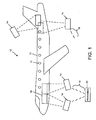
- FIG. 1 is an illustration of a system 10 for laser projection marking on a large object 12, in accordance with a first exemplary embodiment of the present disclosure.
- the system 10 contains a plurality of laser projectors 14.
- An image 16 of a marking is projected in a synchronized form by the plurality of laser projectors 14.
- a computer network 18 provides communication with the laser projectors 14.
- a central workstation 20 communicates with the laser projectors 14 through the computer network 18. The central workstation 20 coordinates the image 16 projected by the laser projectors 14.
- the large object 12 may be, as shown in FIG. 1 , an aircraft, although other similarly sized objects may utilize the embodiments disclosed herein.
- the laser projectors 14, properly coordinated, allow marking the large object 12 in many different locations concurrently in a manner that would not be feasible with a single laser projector. Thus, work may be performed concurrently along the entire large object 12 to paint and/or otherwise mark the large object 12.
- the image 16, while including the marking to be applied to the large object 12, may also include physical features found on the large object 12, such as windows 13. Providing features of the large object 12 in the image 16 may assist in the transformation of the image along the large object 12. Assisting in transformation will improve the proper marking of the large object 12.
- the laser projectors 14 may be in wireless communication with the central workstation 20 via a computer network 18.
- the central workstation 20 may be in communication with a transmitter that is part of the computer network 18.
- the central workstation 20 transmits through the transmitter a wireless signal to the laser projectors 14 to coordinate display of the image 16 on the large object 12.
- the computer network 18 and the central workstation 20 may include devices known to those having ordinary skill in the art for generation and communication of signals to output devices, such as laser projectors 14.
- the central workstation 20 may further divide the image 16 into a plurality of portions of the image 16 such that each laser projector 14 projects a portion of the image 16 and the sum of the projected portions of the image 16 is the whole image 16. Further, the portions of the image 16 projected may overlap and, in some cases, overlap significantly to insure proper projection of the image 16.
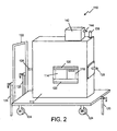
- FIG. 2 is a perspective illustration of an individual laser projector 14 marking on a large object 12, in accordance with the present disclosure.
- the projector 14 is contained within a cart system 110 which contains a purge chamber 112 such as described in co-pending U.S. application Serial No. 12/024,825, filed February 1, 2008 assigned to the common Assignee (Attorney Docket BOEING 07-1231).
- a substantially optically transparent wall 114 is formed along the purge chamber 112.
- a laser projector 116 is mounted within the purge chamber 112.
- the laser projector 14 (shown in FIG. 5 ) is positioned to project a laser beam through the substantially optically transparent wall 114.
- the purge chamber 112 maintains an environment within the purge chamber 112 that allows for safe operation of the laser projector 14.
- the purge chamber 112 may be connected to one or more conduits that transmit one or more gasses into and out of the purge chamber 112.
- the purge chamber 112 may have one or more monitors housed therein that monitor the environment within the purge chamber 112 for the presence of hazardous or explosive gasses.
- the purge chamber 112 may include a device for communicating to a user the presence of hazardous or explosive gasses in the environment within the purge chamber 112 and/or automatically terminating operation of the laser projector 14 upon indication of the presence of hazardous or explosive gasses.
- the substantially optically transparent wall 114 forms a window that allows the laser projector 14 to project a line, image, or other projection out of the purge chamber 112.
- the substantially optically transparent wall 114 may be designed of a material that allows at least partial passage of the radiation emitted from the laser projector 14. Thus, for example, if the laser projector projects a non-visible wavelength of radiation, the substantially optically transparent wall 114 need only allow transmission of that non-visible wavelength of radiation, although the substantially optically transparent wall 114 may allow transmission of a broad band of radiation wavelengths.
- the laser projector 14 may be any device known in the industry for transmitting one or more beams of radiation.
- the laser projector 14 may include hardware and software for accurately projecting images onto uneven, three dimensional objects.
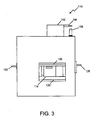
- FIG. 3 is a front illustration of the system 110 for laser projection marking on a large object 12 shown in FIG. 1 , in accordance with the present disclosure.
- the system 110 includes a protective wall 118 movable between a first position (shown in FIG. 3 ) and a second position (shown in FIG. 2 ), wherein the first position substantially overlaps the substantially optically transparent wall 114 and the second position substantially reveals the substantially optically transparent wall 114.
- the protective wall 118 may be utilized when practical to protect the substantially optically transparent wall 114.
- the system 110 includes a cart 122 (shown in FIG. 2 ) having a plurality of wheels 124, wherein the purge chamber 112 is mounted to the cart 122.
- the cart 122 allows the purge chamber 112 to be rolled to various locations for use of the laser projector 14.
- the system 110 includes at least one pivot pin 126 mounted to an exterior surface of the purge chamber 112.
- the purge chamber 112 may have pivot pins 126 on opposing sides of the purge chamber 112.
- the purge chamber 112 may be rotated, for instance, ninety degrees on the pivot pins 126.
- the pivot pins 126 may also be used to pick up the purge chamber 112 with a forklift.
- at least one fork pocket may be formed in the purge chamber 112.
- the fork pocket may be sized to receive a fork of a forklift, allowing the purge chamber 112 to be lifted with the forklift.
- the system 110 includes a wireless communications device 136 mounted within the purge chamber 112 and wired to the laser projector 14.
- the wireless communications device 136 allows communications to the laser projector 14 through the purge chamber 112.
- the system 110 may include an antenna 138 mounted to the purge chamber 112 at least partially exterior to the purge chamber 112.
- the antenna 138 is in communication with the wireless communications device 136 and may provide enhanced transmission of a signal from the wireless communications device 136.
- the wireless communications device 136 and antenna 138 may be commercially available wireless communications products.
- the wireless communications device 136 may be integral with antenna 138:
- the wireless communications device 136 may, for instance, be used to transmit images to the laser projector 14 for projection.
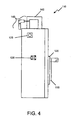
- FIG. 4 is a side illustration of the system 110 for laser projection marking on a large object 12 shown in FIG. 1 , in accordance with the present disclosure.
- a conduit 140 is connected to the purge chamber 112 for gas transmission.
- the conduit 140 is shown connected to the purge chamber 112 through a purge controller 142 mounted to the purge chamber 112.
- the purge controller 142 controls gas transmission through the conduit 140.
- the purge controller 142 may also have a release valve 144 ( FIG. 5 ) mounted thereto. The release valve 144 may be operated to release an excess of gas pressure within the purge chamber 112.
- FIG. 5 is an interior illustration of the system 110 for laser projection marking on a large object 12 shown in FIG. 1 , in accordance with the present disclosure.
- a power strip 132 may be mounted within the purge chamber 112 for connection to the laser projector 14.
- the illustrated embodiment also shows devices for wireless communication to the laser projector 14 and, while both devices may be provided, it may be more likely that either wired or wireless communication to the laser projector 14 be provided.
- FIG. 6 is an illustration of the system 110 for laser projection marking on a large object 12, in accordance with a first exemplary embodiment of the present disclosure.
- the system 110 contains a plurality of laser projectors 14A, 14B.
- An image 116 of a marking is projected in a synchronized form by the plurality of laser projectors 14A, 14B.
- a computer network 118 provides communication with the laser projectors 14A, 14B.
- a central workstation 20 communicates with the laser projectors 14A, 14B through the computer network 118. The central workstation 20 coordinates the image 116 projected by the laser projectors 14A, 14B.
- the laser projectors include both mobile laser projectors 14A and stationary laser projectors 14B.
- stationary laser projectors 14B may be convenient in that transformation of the image 116 may be easier and more reliable.
- some markings may be required in locations that are not convenient for stationary laser projectors 14B and, for those markings, mobile laser projectors 14A may be useful.
- the system 110 may be conveniently adopted with between 3 and approximately 30 or more laser projectors 14A, 14B in which a percentage, e.g., approximately twenty percent of the laser projectors are mobile laser projectors 14A, and the balance, approximately eighty percent of the laser projectors are stationary laser projectors 14B. Further, for a larger number of laser projectors, it may be useful to adopt more than one central workstation 20.
- FIG. 7 is an illustration showing the alignment of images projected by stationary laser projectors 14B.
- the images 182, 183, 184, 185 overlap at predetermined points on the large object. These points may be marked using small retro-reflective surfaces 170 to ensure that all stationary laser projectors work as a single system.
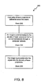
- FIG. 8 is a flowchart 200 illustrating a method of providing the abovementioned system 10 for laser projection marking on a large object 12, in accordance with the above described exemplary embodiment.
- any process descriptions or blocks in flow charts should be understood as representing modules, segments, portions of code, or steps that include one or more instructions for implementing specific logical functions in the process, and alternate implementations are included within the scope of the present disclosure in which functions may be executed out of order from that shown or discussed, including substantially concurrently or in reverse order, depending on the functionality involved.
- a plurality of laser projectors 14 is calibrated about the object 12.
- An image 16 is communicated to the plurality of laser projectors 14 from a central workstation 20 through a computer network 18 (block 204).
- the image 16 is projected onto the object 12 with the plurality of laser projectors 14 (block 206).
Landscapes
- Physics & Mathematics (AREA)
- General Physics & Mathematics (AREA)
- Theoretical Computer Science (AREA)
- Marketing (AREA)
- Accounting & Taxation (AREA)
- Engineering & Computer Science (AREA)
- Business, Economics & Management (AREA)
- Projection Apparatus (AREA)
- Lasers (AREA)
- Thermal Transfer Or Thermal Recording In General (AREA)
- Illuminated Signs And Luminous Advertising (AREA)
- Laser Beam Processing (AREA)
- Control Of Indicators Other Than Cathode Ray Tubes (AREA)
- Length Measuring Devices By Optical Means (AREA)
Abstract
Description
- The present disclosure is generally related to laser projection and, more particularly, is related to a laser projector system for marking company liveries on large-scale vehicle surfaces. The invention has particular utility for use with an aircraft and will be described in connection with such utility, although other utilities are contemplated.
- Large-scale vehicles, such as airplanes, may be provided with customer liveries during the manufacturing process. The liveries may include one or more logos of the vehicle as well as identifying indicia for the vehicle. The liveries may be formed using one or more colors.
- Presently, custom Mylar tools are constructed to enable the application of liveries to large-scale vehicles. Mylar tools are expensive to build and maintain. Typically, these Mylar tools are hand made for every paint design. Changes to a design generally require a new hand built set of tools. Once the set of Mylar tools are made, testing is done to insure proper fit and function. The building and testing is performed on the vehicle in final assembly after substantial completion of vehicle construction. Thus, the building and testing requires access to the vehicle and may require dangerous positioning of tooling personnel (as liveries are regularly positioned in locations that require staging or other structures or support to access). It is not unusual for a Mylar tool set for a decorative layout to be constructed over a thirty-day schedule. Flaws found in testing may require another thirty-day schedule to complete a revised Mylar tool set. Also, the Mylar tool set may be crafted to the specifications of the vehicle and as-built irregularities in a surface of the vehicle may require reconstruction of the Mylar tool set.
- Therefore, it would be advantageous to have a method and apparatus that overcomes the problems discussed above.
- Embodiments of the present disclosure provide a system and method for laser projection marking on a large object. Briefly described, in architecture, one embodiment of the system, among others, can be implemented as follows. The system contains a plurality of laser projectors. An image of a marking is projected in a synchronized form by the plurality of laser projectors. A computer network provides communication with the laser projectors. A central workstation communicates with the laser projectors through the computer network. The central workstation coordinates the image projected by the laser projectors.
- The present disclosure can also be viewed as providing methods for laser projection marking on a large object. In this regard, one embodiment of such a method, among others, can be broadly summarized by the following steps: calibrating a plurality of laser projectors about the object; communicating an image to the plurality of laser projectors from a central workstation through a computer network; and projecting the image onto the object with the plurality of laser projectors.
- Other systems, methods, features, and advantages of the present disclosure will be or become apparent to one with skill in the art upon examination of the following drawings and detailed description. The features, functions and advantages that have been discussed can be achieved independently in various embodiments of the present disclosure or may be combined in yet other embodiments further details of which can be seen with reference to the following description and drawings.
- Many aspects of the invention can be better understood with reference to the following drawings. The components in the drawings are not necessarily to scale, emphasis instead being placed upon clearly illustrating the principles of the present invention. Moreover, in the drawings, like reference numerals designate corresponding parts throughout the several views.
-
FIG. 1 is an illustration of a system for laser projection marking on a large object, in accordance with one embodiment of the present disclosure; -
FIG. 2 is a perspective illustration of an individual system for laser projection marking on a large object, in accordance with the present disclosure; -
FIG. 3 is a front illustration of the system shown inFIG. 2 ; -
FIG. 4 is a side illustration of the system shown inFIG. 2 ; -
FIG. 5 is an interior illustration of the system shown inFIG. 2 ; -
FIG. 6 is an illustration of a system for laser projection marking on a large object, in accordance with the second exemplary embodiment of the present disclosure; -
FIG. 7 is an illustration showing the alignment of images projected by the system for laser projection marking on a large object, in accordance with the second exemplary embodiment of the present disclosure; and -
FIG. 8 is a flowchart illustrating a method of providing the abovementioned system for laser projection marking on a large object, in accordance with the present disclosure. -
FIG. 1 is an illustration of asystem 10 for laser projection marking on alarge object 12, in accordance with a first exemplary embodiment of the present disclosure. Thesystem 10 contains a plurality oflaser projectors 14. Animage 16 of a marking is projected in a synchronized form by the plurality oflaser projectors 14. Acomputer network 18 provides communication with thelaser projectors 14. Acentral workstation 20 communicates with thelaser projectors 14 through thecomputer network 18. Thecentral workstation 20 coordinates theimage 16 projected by thelaser projectors 14. - The
large object 12 may be, as shown inFIG. 1 , an aircraft, although other similarly sized objects may utilize the embodiments disclosed herein. Thelaser projectors 14, properly coordinated, allow marking thelarge object 12 in many different locations concurrently in a manner that would not be feasible with a single laser projector. Thus, work may be performed concurrently along the entirelarge object 12 to paint and/or otherwise mark thelarge object 12. - The
image 16, while including the marking to be applied to thelarge object 12, may also include physical features found on thelarge object 12, such aswindows 13. Providing features of thelarge object 12 in theimage 16 may assist in the transformation of the image along thelarge object 12. Assisting in transformation will improve the proper marking of thelarge object 12. - As shown in
FIG. 1 , thelaser projectors 14 may be in wireless communication with thecentral workstation 20 via acomputer network 18. Thecentral workstation 20 may be in communication with a transmitter that is part of thecomputer network 18. Thecentral workstation 20 transmits through the transmitter a wireless signal to thelaser projectors 14 to coordinate display of theimage 16 on thelarge object 12. Thecomputer network 18 and thecentral workstation 20 may include devices known to those having ordinary skill in the art for generation and communication of signals to output devices, such aslaser projectors 14. Thecentral workstation 20 may further divide theimage 16 into a plurality of portions of theimage 16 such that eachlaser projector 14 projects a portion of theimage 16 and the sum of the projected portions of theimage 16 is thewhole image 16. Further, the portions of theimage 16 projected may overlap and, in some cases, overlap significantly to insure proper projection of theimage 16. -
FIG. 2 is a perspective illustration of anindividual laser projector 14 marking on alarge object 12, in accordance with the present disclosure. Theprojector 14 is contained within acart system 110 which contains apurge chamber 112 such as described in co-pendingU.S. application Serial No. 12/024,825, filed February 1, 2008 assigned to the common Assignee (Attorney Docket BOEING 07-1231). A substantially opticallytransparent wall 114 is formed along thepurge chamber 112. Alaser projector 116 is mounted within thepurge chamber 112. The laser projector 14 (shown inFIG. 5 ) is positioned to project a laser beam through the substantially opticallytransparent wall 114. - The
purge chamber 112 maintains an environment within thepurge chamber 112 that allows for safe operation of thelaser projector 14. Thepurge chamber 112 may be connected to one or more conduits that transmit one or more gasses into and out of thepurge chamber 112. Thepurge chamber 112 may have one or more monitors housed therein that monitor the environment within thepurge chamber 112 for the presence of hazardous or explosive gasses. Thepurge chamber 112 may include a device for communicating to a user the presence of hazardous or explosive gasses in the environment within thepurge chamber 112 and/or automatically terminating operation of thelaser projector 14 upon indication of the presence of hazardous or explosive gasses. - The substantially optically
transparent wall 114 forms a window that allows thelaser projector 14 to project a line, image, or other projection out of thepurge chamber 112. The substantially opticallytransparent wall 114 may be designed of a material that allows at least partial passage of the radiation emitted from thelaser projector 14. Thus, for example, if the laser projector projects a non-visible wavelength of radiation, the substantially opticallytransparent wall 114 need only allow transmission of that non-visible wavelength of radiation, although the substantially opticallytransparent wall 114 may allow transmission of a broad band of radiation wavelengths. - The
laser projector 14 may be any device known in the industry for transmitting one or more beams of radiation. Thelaser projector 14 may include hardware and software for accurately projecting images onto uneven, three dimensional objects. -
FIG. 3 is a front illustration of thesystem 110 for laser projection marking on alarge object 12 shown inFIG. 1 , in accordance with the present disclosure. Thesystem 110 includes aprotective wall 118 movable between a first position (shown inFIG. 3 ) and a second position (shown inFIG. 2 ), wherein the first position substantially overlaps the substantially opticallytransparent wall 114 and the second position substantially reveals the substantially opticallytransparent wall 114. As thesystem 110 is intended for operation in hazardous sites having heavy machinery and/or painting that could harm or frustrate the purpose of the substantially opticallytransparent wall 114, theprotective wall 118 may be utilized when practical to protect the substantially opticallytransparent wall 114. - The
system 110 includes a cart 122 (shown inFIG. 2 ) having a plurality ofwheels 124, wherein thepurge chamber 112 is mounted to thecart 122. Thecart 122 allows thepurge chamber 112 to be rolled to various locations for use of thelaser projector 14. - The
system 110 includes at least onepivot pin 126 mounted to an exterior surface of thepurge chamber 112. As shown inFIG. 3 , thepurge chamber 112 may have pivot pins 126 on opposing sides of thepurge chamber 112. When mounted on the pivot pins 126, thepurge chamber 112 may be rotated, for instance, ninety degrees on the pivot pins 126. Providing the opportunity to rotate thepurge chamber 112, provides an opportunity to rotate thelaser projector 14 and project images at various angles, The pivot pins 126 may also be used to pick up thepurge chamber 112 with a forklift. Not shown, at least one fork pocket may be formed in thepurge chamber 112. The fork pocket may be sized to receive a fork of a forklift, allowing thepurge chamber 112 to be lifted with the forklift. - The
system 110 includes awireless communications device 136 mounted within thepurge chamber 112 and wired to thelaser projector 14. Thewireless communications device 136 allows communications to thelaser projector 14 through thepurge chamber 112. As shown inFIG. 3 , thesystem 110 may include anantenna 138 mounted to thepurge chamber 112 at least partially exterior to thepurge chamber 112. Theantenna 138 is in communication with thewireless communications device 136 and may provide enhanced transmission of a signal from thewireless communications device 136. Thewireless communications device 136 andantenna 138 may be commercially available wireless communications products. Thewireless communications device 136 may be integral with antenna 138: Thewireless communications device 136 may, for instance, be used to transmit images to thelaser projector 14 for projection. -
FIG. 4 is a side illustration of thesystem 110 for laser projection marking on alarge object 12 shown inFIG. 1 , in accordance with the present disclosure. Aconduit 140 is connected to thepurge chamber 112 for gas transmission. Theconduit 140 is shown connected to thepurge chamber 112 through apurge controller 142 mounted to thepurge chamber 112. Thepurge controller 142 controls gas transmission through theconduit 140. Thepurge controller 142 may also have a release valve 144 (FIG. 5 ) mounted thereto. Therelease valve 144 may be operated to release an excess of gas pressure within thepurge chamber 112. -
FIG. 5 is an interior illustration of thesystem 110 for laser projection marking on alarge object 12 shown inFIG. 1 , in accordance with the present disclosure. As shown inFIG. 5 , apower strip 132 may be mounted within thepurge chamber 112 for connection to thelaser projector 14. The illustrated embodiment also shows devices for wireless communication to thelaser projector 14 and, while both devices may be provided, it may be more likely that either wired or wireless communication to thelaser projector 14 be provided. -
FIG. 6 is an illustration of thesystem 110 for laser projection marking on alarge object 12, in accordance with a first exemplary embodiment of the present disclosure. Thesystem 110 contains a plurality oflaser projectors image 116 of a marking is projected in a synchronized form by the plurality oflaser projectors computer network 118 provides communication with thelaser projectors central workstation 20 communicates with thelaser projectors computer network 118. Thecentral workstation 20 coordinates theimage 116 projected by thelaser projectors - As shown in
FIG. 6 , the laser projectors include bothmobile laser projectors 14A andstationary laser projectors 14B. For repeated marking/manufacture of similarlarge objects 12,stationary laser projectors 14B may be convenient in that transformation of theimage 116 may be easier and more reliable. However, some markings may be required in locations that are not convenient forstationary laser projectors 14B and, for those markings,mobile laser projectors 14A may be useful. Thesystem 110 may be conveniently adopted with between 3 and approximately 30 ormore laser projectors mobile laser projectors 14A, and the balance, approximately eighty percent of the laser projectors arestationary laser projectors 14B. Further, for a larger number of laser projectors, it may be useful to adopt more than onecentral workstation 20. -
FIG. 7 is an illustration showing the alignment of images projected bystationary laser projectors 14B. Theimages reflective surfaces 170 to ensure that all stationary laser projectors work as a single system. -
FIG. 8 is aflowchart 200 illustrating a method of providing theabovementioned system 10 for laser projection marking on alarge object 12, in accordance with the above described exemplary embodiment. It should be noted that any process descriptions or blocks in flow charts should be understood as representing modules, segments, portions of code, or steps that include one or more instructions for implementing specific logical functions in the process, and alternate implementations are included within the scope of the present disclosure in which functions may be executed out of order from that shown or discussed, including substantially concurrently or in reverse order, depending on the functionality involved. - As is shown by
block 202, a plurality oflaser projectors 14 is calibrated about theobject 12. Animage 16 is communicated to the plurality oflaser projectors 14 from acentral workstation 20 through a computer network 18 (block 204). Theimage 16 is projected onto theobject 12 with the plurality of laser projectors 14 (block 206). - It should be emphasized that the above-described embodiments of the present disclosure, particularly, any "preferred" embodiments, are merely possible examples of implementations, merely set forth for a clear understanding of the principles of the present disclosure. Many variations and modifications may be made to the above-described embodiments without departing substantially from the spirit and principles of the disclosure. All such modifications and variations are intended to be included herein within the scope of this disclosure and protected by the following claims.
Claims (15)
- An apparatus for laser projection marking on a vehicle exterior, the apparatus characterized by comprising:a plurality of laser projectors 14, 14A, 14B;an image 16, 116 on the vehicle exterior projected in a synchronized form by the plurality of laser projectors 14, 14A, 14B;a computer network 18, 118 in communication with the laser projectors 14, 14A, 14B; anda central workstation 20 in communication with the laser projectors 14, 14A, 14B through the computer network 18, 118, whereby the central workstation 20 coordinates the image projected by the laser projectors 14, 14A, 14B.
- The apparatus of claim 1, characterized by further comprising a plurality of purge chambers 112, each purge chamber 112 having a substantially optically transparent wall 114 formed along the purge chamber 112, wherein each laser projector 14, 14A, 14B is mounted within one of the purge chambers 112 and positioned to project a laser beam through the substantially optically transparent wall.
- The apparatus of claim 2, characterized by further comprising at least one cart 122 having a plurality of wheels 124, wherein one of the purge chambers 112 is mounted to the cart 122.
- The apparatus of claim 1, characterized in that the communication 18, 118 between the computer network and the laser projectors is wireless.
- The apparatus of claim 1, characterized in that the plurality of laser projectors further comprises a plurality of stationary laser projectors 114B and a plurality of mobile laser projectors 114A, and wherein each of the mobile laser projectors is mounted to a cart 122.
- The apparatus of claim 1, characterized in that the plurality of laser projectors further comprises between 3 and 30 laser projectors 14, 14A, 14B.
- The apparatus of claim 1, characterized by further comprising a plurality of central workstations 20 in communication with the laser projectors 14, 14A, 14B through the computer network 18, 118, whereby the central workstations 20 coordinate the image 116 projected by the laser projectors 14, 14A, 14B.
- The apparatus of claim 1, characterized in that the laser projectors 14, 14A, 14B project a plurality of portions of the image 116.
- The apparatus of claim 8, characterized in that the portions of the image 116 overlap as projected by the laser projectors 14, 14A, 14B.
- The apparatus of claim 8, characterized in that the portions of the image combine to form the image 116.
- A method for laser marking on a large object, the method characterized by comprising the steps of:calibrating a plurality of laser projectors 14, 14A, 14B about the object;communicating an image to the plurality of laser projectors 14, 14A, 14B from a central workstation 20 through a computer network 18, 118; andprojecting the image 116 onto the object with the plurality of laser projectors 14, 14A, 14B.
- The method of claim 11, characterized by further comprising:mounting at least one of the laser projectors 14, 14A, 14B within a purge chamber 112; andpositioning the laser projector 14, 14A, 14B to project a laser beam through a substantially optically transparent wall 114 of the purge chamber 112.
- The method of claim 11, characterized by further comprising mounting at least a portion of the plurality of laser projectors 14B in stationary positions.
- The method of claim 11, characterized by further comprising including characteristics of the large object 12 in the image, thereby aiding in a transformation of the image along the large object.
- The method of claim 11, characterized in that the step of projecting the image 116 further comprises each laser projector 14, 14A, 14B projecting one of a plurality of portions of the image, whereby the portions of the image combine to form the image 116.
Applications Claiming Priority (1)
| Application Number | Priority Date | Filing Date | Title |
|---|---|---|---|
| US12/024,853 US7887191B2 (en) | 2008-02-01 | 2008-02-01 | Method and system for making a large object itilizing laser projection |
Publications (3)
| Publication Number | Publication Date |
|---|---|
| EP2085954A2 true EP2085954A2 (en) | 2009-08-05 |
| EP2085954A3 EP2085954A3 (en) | 2012-07-18 |
| EP2085954B1 EP2085954B1 (en) | 2017-03-08 |
Family
ID=40640337
Family Applications (1)
| Application Number | Title | Priority Date | Filing Date |
|---|---|---|---|
| EP08252780.5A Active EP2085954B1 (en) | 2008-02-01 | 2008-08-21 | Laser projection marking system |
Country Status (9)
| Country | Link |
|---|---|
| US (1) | US7887191B2 (en) |
| EP (1) | EP2085954B1 (en) |
| JP (1) | JP2009186974A (en) |
| KR (1) | KR101146891B1 (en) |
| CN (1) | CN101497278B (en) |
| AU (1) | AU2008205428B2 (en) |
| CA (1) | CA2638607C (en) |
| ES (1) | ES2619653T3 (en) |
| RU (1) | RU2008142189A (en) |
Cited By (1)
| Publication number | Priority date | Publication date | Assignee | Title |
|---|---|---|---|---|
| EP3342717A1 (en) * | 2016-12-28 | 2018-07-04 | Airbus Operations, S.L. | Illumination device for illuminating the vertical tail plane of an aircraft and aircraft with exterior illumination on its vertical tail plane |
Families Citing this family (18)
| Publication number | Priority date | Publication date | Assignee | Title |
|---|---|---|---|---|
| US7887190B2 (en) * | 2008-02-01 | 2011-02-15 | The Boeing Company | Method and system for an enclosed, portable, volatile environment laser projector |
| US8690715B2 (en) * | 2010-09-13 | 2014-04-08 | Steven D. Vogt | Light source projecting lines defining activity area |
| US8622554B1 (en) * | 2011-05-26 | 2014-01-07 | Twilight Features, Inc. | Portable weather-resistant unit for video projectors |
| US8651664B2 (en) * | 2011-06-27 | 2014-02-18 | The Boeing Company | Aircraft projector system and movement detection system responsive to aircraft structure movement |
| FR2982736B1 (en) * | 2011-11-18 | 2013-12-13 | Airbus Operations Sas | METHOD AND DEVICE FOR VISIBLE IMPARRINATION OF AVIAN SPECIES, ESPECIALLY FOR AN AIRCRAFT. |
| US9324248B2 (en) * | 2012-09-04 | 2016-04-26 | The Boeing Company | Exterior aircraft display system |
| US8933819B1 (en) | 2012-09-04 | 2015-01-13 | The Boeing Company | Exterior aircraft display system |
| WO2015021173A1 (en) | 2013-08-06 | 2015-02-12 | Laser Projection Technologies, Inc. | Virtual laser projection system and method |
| FR3021784B1 (en) | 2014-05-27 | 2017-10-13 | European Aeronautic Defence & Space Co Eads France | METHOD FOR PROJECTING VIRTUAL DATA AND DEVICE FOR SAID PROJECTION |
| CN105923162A (en) * | 2016-06-17 | 2016-09-07 | 苏州大学 | A UAV automatic inkjet device |
| CN106077779A (en) * | 2016-08-26 | 2016-11-09 | 芜湖明特威工程机械有限公司 | A kind of electromagnetic platen formula sword plate edge milling machines of band location |
| US12007220B2 (en) * | 2017-12-29 | 2024-06-11 | II John Tyson | Optical structural health monitoring |
| US11486697B1 (en) * | 2017-12-29 | 2022-11-01 | II John Tyson | Optical structural health monitoring |
| US10807383B2 (en) | 2018-09-24 | 2020-10-20 | The Boeing Company | Robotic printing system for an aircraft exterior |
| US11396385B2 (en) * | 2019-01-14 | 2022-07-26 | The Boeing Company | Method and apparatus for remote optical measurement of the position of a surface |
| US11585653B2 (en) | 2019-01-14 | 2023-02-21 | The Boeing Company | Method and apparatus for remote optical measurement of the position of a surface |
| CN110813934A (en) * | 2019-11-29 | 2020-02-21 | 北京京诚之星科技开发有限公司 | An online laser descaling cleaning device and system |
| CN114758596B (en) * | 2022-03-17 | 2024-03-26 | 深圳影一映画文化传播有限公司 | Mobile projection equipment for creative culture advertisement |
Citations (1)
| Publication number | Priority date | Publication date | Assignee | Title |
|---|---|---|---|---|
| US2482508A (en) | 1946-08-21 | 1949-09-20 | Monsanto Chemicals | Modified methylol melamine resins |
Family Cites Families (19)
| Publication number | Priority date | Publication date | Assignee | Title |
|---|---|---|---|---|
| JPS5257526A (en) * | 1975-11-06 | 1977-05-12 | Yasuo Ikeda | Band heater |
| US5388318A (en) * | 1992-10-09 | 1995-02-14 | Laharco, Inc. | Method for defining a template for assembling a structure |
| US5425179A (en) * | 1993-10-22 | 1995-06-20 | The Charles Machine Works, Inc. | Optical sensor for measuring inclination angles |
| US5436027A (en) * | 1993-12-23 | 1995-07-25 | The Boeing Company | Method of applying a coating design |
| US5932119A (en) | 1996-01-05 | 1999-08-03 | Lazare Kaplan International, Inc. | Laser marking system |
| US5771260A (en) * | 1996-10-04 | 1998-06-23 | Excimer Laser Systems, Inc. | Enclosure system for laser optical systems and devices |
| US7079157B2 (en) | 2000-03-17 | 2006-07-18 | Sun Microsystems, Inc. | Matching the edges of multiple overlapping screen images |
| JP3497805B2 (en) | 2000-08-29 | 2004-02-16 | オリンパス株式会社 | Image projection display device |
| JP2002108563A (en) * | 2000-10-04 | 2002-04-12 | Asahi Eng Co Ltd | Large display with internal pressure explosion-proof structure |
| JP4615146B2 (en) * | 2001-05-18 | 2011-01-19 | 旭化成エンジニアリング株式会社 | Operation indicator with explosion-proof construction |
| JP2003200700A (en) | 2002-01-07 | 2003-07-15 | Masao Yoshida | Aggregate transparent body having outer markings |
| US6931149B2 (en) * | 2002-04-19 | 2005-08-16 | Norsk Elektro Optikk A/S | Pipeline internal inspection device and method |
| US7463368B2 (en) | 2003-09-10 | 2008-12-09 | Metris Canada Inc | Laser projection system, intelligent data correction system and method |
| JP4732347B2 (en) * | 2003-09-10 | 2011-07-27 | ニコン メトロロジー エヌブイ | Method for projecting a laser template |
| US7977026B2 (en) * | 2004-02-06 | 2011-07-12 | Rohm And Haas Electronic Materials Llc | Imaging methods |
| JP2006330329A (en) * | 2005-05-26 | 2006-12-07 | Seiko Epson Corp | Multi-projection display |
| US8782878B2 (en) * | 2005-09-28 | 2014-07-22 | Nikon Metrology Nv | Fastener automation system |
| US20080007400A1 (en) * | 2006-07-07 | 2008-01-10 | Terry Murphy | Image projection system |
| FR2907246B1 (en) * | 2006-10-12 | 2008-12-12 | Airbus France Sas | METHOD AND DEVICES FOR PROJECTING TWO-DIMENSIONAL PATTERNS ON COMPLEX SURFACES OF THREE-DIMENSIONAL OBJECTS |
-
2008
- 2008-02-01 US US12/024,853 patent/US7887191B2/en active Active
- 2008-08-11 CA CA2638607A patent/CA2638607C/en active Active
- 2008-08-14 AU AU2008205428A patent/AU2008205428B2/en active Active
- 2008-08-21 ES ES08252780.5T patent/ES2619653T3/en active Active
- 2008-08-21 EP EP08252780.5A patent/EP2085954B1/en active Active
- 2008-08-29 JP JP2008221996A patent/JP2009186974A/en active Pending
- 2008-09-08 KR KR1020080088369A patent/KR101146891B1/en active Active
- 2008-09-12 CN CN200810149433.8A patent/CN101497278B/en active Active
- 2008-10-24 RU RU2008142189/28A patent/RU2008142189A/en not_active Application Discontinuation
Patent Citations (1)
| Publication number | Priority date | Publication date | Assignee | Title |
|---|---|---|---|---|
| US2482508A (en) | 1946-08-21 | 1949-09-20 | Monsanto Chemicals | Modified methylol melamine resins |
Cited By (2)
| Publication number | Priority date | Publication date | Assignee | Title |
|---|---|---|---|---|
| EP3342717A1 (en) * | 2016-12-28 | 2018-07-04 | Airbus Operations, S.L. | Illumination device for illuminating the vertical tail plane of an aircraft and aircraft with exterior illumination on its vertical tail plane |
| US10269274B2 (en) | 2016-12-28 | 2019-04-23 | Airbus Operations S.L. | Illumination device for illuminating the vertical tail plane of an aircraft and aircraft with exterior illumination on its vertical tail plane |
Also Published As
| Publication number | Publication date |
|---|---|
| CN101497278B (en) | 2013-03-06 |
| JP2009186974A (en) | 2009-08-20 |
| US20090195753A1 (en) | 2009-08-06 |
| RU2008142189A (en) | 2010-04-27 |
| KR101146891B1 (en) | 2012-05-16 |
| CA2638607A1 (en) | 2009-08-01 |
| EP2085954A3 (en) | 2012-07-18 |
| CA2638607C (en) | 2012-10-30 |
| KR20090084638A (en) | 2009-08-05 |
| AU2008205428A1 (en) | 2009-08-20 |
| ES2619653T3 (en) | 2017-06-26 |
| CN101497278A (en) | 2009-08-05 |
| EP2085954B1 (en) | 2017-03-08 |
| US7887191B2 (en) | 2011-02-15 |
| AU2008205428B2 (en) | 2013-06-20 |
Similar Documents
| Publication | Publication Date | Title |
|---|---|---|
| CA2638607C (en) | Method and system for marking a large object utilizing laser projection | |
| CN111630517B (en) | Three-dimensional pattern display system, three-dimensional pattern display method and program | |
| US7887190B2 (en) | Method and system for an enclosed, portable, volatile environment laser projector | |
| CN101907440B (en) | CMM arm with exoskeleton | |
| US8294571B2 (en) | Object location and reporting system for harsh RF environments | |
| CA2852519C (en) | Robotic-mounted monument system for metrology systems | |
| KR20060015557A (en) | Cmm arm with exoskeleton | |
| JP7438680B2 (en) | Augmented reality system with active portable anchor | |
| CN204195075U (en) | A kind of laser welding platform based on hand-held control | |
| ITUA20164597A1 (en) | POSITIONING SYSTEM AND METHOD FOR DETERMINING AN OPERATIONAL POSITION OF AN AIR DEVICE | |
| KR101155443B1 (en) | The position control apparatus and method for module transporter | |
| KR100868230B1 (en) | Wall marking method using IPS | |
| KR20070053070A (en) | Loading position display method of atypical vehicle and its device | |
| IT201600107650A1 (en) | Feeler device and localization procedure of a feeler device for the measurement of large objects | |
| JPS638805A (en) | Self-contained correcting device for stereoscopic pantograph | |
| CN104176089A (en) | Out-of-gauge detection system for rail freight car |
Legal Events
| Date | Code | Title | Description |
|---|---|---|---|
| PUAI | Public reference made under article 153(3) epc to a published international application that has entered the european phase |
Free format text: ORIGINAL CODE: 0009012 |
|
| 17P | Request for examination filed |
Effective date: 20080901 |
|
| AK | Designated contracting states |
Kind code of ref document: A2 Designated state(s): AT BE BG CH CY CZ DE DK EE ES FI FR GB GR HR HU IE IS IT LI LT LU LV MC MT NL NO PL PT RO SE SI SK TR |
|
| AX | Request for extension of the european patent |
Extension state: AL BA MK RS |
|
| RIC1 | Information provided on ipc code assigned before grant |
Ipc: B25H 7/00 20060101ALN20110317BHEP Ipc: G09F 19/18 20060101AFI20090609BHEP |
|
| PUAL | Search report despatched |
Free format text: ORIGINAL CODE: 0009013 |
|
| AK | Designated contracting states |
Kind code of ref document: A3 Designated state(s): AT BE BG CH CY CZ DE DK EE ES FI FR GB GR HR HU IE IS IT LI LT LU LV MC MT NL NO PL PT RO SE SI SK TR |
|
| AX | Request for extension of the european patent |
Extension state: AL BA MK RS |
|
| RIC1 | Information provided on ipc code assigned before grant |
Ipc: B25H 7/00 20060101ALN20120613BHEP Ipc: G09F 19/18 20060101AFI20120613BHEP Ipc: G03B 21/00 20060101ALI20120613BHEP |
|
| AKX | Designation fees paid |
Designated state(s): AT BE BG CH CY CZ DE DK EE ES FI FR GB GR HR HU IE IS IT LI LT LU LV MC MT NL NO PL PT RO SE SI SK TR |
|
| 17Q | First examination report despatched |
Effective date: 20151012 |
|
| GRAP | Despatch of communication of intention to grant a patent |
Free format text: ORIGINAL CODE: EPIDOSNIGR1 |
|
| INTG | Intention to grant announced |
Effective date: 20160920 |
|
| GRAS | Grant fee paid |
Free format text: ORIGINAL CODE: EPIDOSNIGR3 |
|
| GRAA | (expected) grant |
Free format text: ORIGINAL CODE: 0009210 |
|
| AK | Designated contracting states |
Kind code of ref document: B1 Designated state(s): AT BE BG CH CY CZ DE DK EE ES FI FR GB GR HR HU IE IS IT LI LT LU LV MC MT NL NO PL PT RO SE SI SK TR |
|
| REG | Reference to a national code |
Ref country code: GB Ref legal event code: FG4D |
|
| REG | Reference to a national code |
Ref country code: CH Ref legal event code: EP Ref country code: AT Ref legal event code: REF Ref document number: 874168 Country of ref document: AT Kind code of ref document: T Effective date: 20170315 |
|
| REG | Reference to a national code |
Ref country code: IE Ref legal event code: FG4D |
|
| REG | Reference to a national code |
Ref country code: DE Ref legal event code: R096 Ref document number: 602008049057 Country of ref document: DE |
|
| REG | Reference to a national code |
Ref country code: SE Ref legal event code: TRGR |
|
| REG | Reference to a national code |
Ref country code: ES Ref legal event code: FG2A Ref document number: 2619653 Country of ref document: ES Kind code of ref document: T3 Effective date: 20170626 |
|
| REG | Reference to a national code |
Ref country code: LT Ref legal event code: MG4D |
|
| REG | Reference to a national code |
Ref country code: NL Ref legal event code: MP Effective date: 20170308 |
|
| PG25 | Lapsed in a contracting state [announced via postgrant information from national office to epo] |
Ref country code: HR Free format text: LAPSE BECAUSE OF FAILURE TO SUBMIT A TRANSLATION OF THE DESCRIPTION OR TO PAY THE FEE WITHIN THE PRESCRIBED TIME-LIMIT Effective date: 20170308 Ref country code: GR Free format text: LAPSE BECAUSE OF FAILURE TO SUBMIT A TRANSLATION OF THE DESCRIPTION OR TO PAY THE FEE WITHIN THE PRESCRIBED TIME-LIMIT Effective date: 20170609 Ref country code: NO Free format text: LAPSE BECAUSE OF FAILURE TO SUBMIT A TRANSLATION OF THE DESCRIPTION OR TO PAY THE FEE WITHIN THE PRESCRIBED TIME-LIMIT Effective date: 20170608 Ref country code: LT Free format text: LAPSE BECAUSE OF FAILURE TO SUBMIT A TRANSLATION OF THE DESCRIPTION OR TO PAY THE FEE WITHIN THE PRESCRIBED TIME-LIMIT Effective date: 20170308 Ref country code: FI Free format text: LAPSE BECAUSE OF FAILURE TO SUBMIT A TRANSLATION OF THE DESCRIPTION OR TO PAY THE FEE WITHIN THE PRESCRIBED TIME-LIMIT Effective date: 20170308 |
|
| REG | Reference to a national code |
Ref country code: AT Ref legal event code: MK05 Ref document number: 874168 Country of ref document: AT Kind code of ref document: T Effective date: 20170308 |
|
| REG | Reference to a national code |
Ref country code: FR Ref legal event code: PLFP Year of fee payment: 10 |
|
| PG25 | Lapsed in a contracting state [announced via postgrant information from national office to epo] |
Ref country code: BG Free format text: LAPSE BECAUSE OF FAILURE TO SUBMIT A TRANSLATION OF THE DESCRIPTION OR TO PAY THE FEE WITHIN THE PRESCRIBED TIME-LIMIT Effective date: 20170608 Ref country code: LV Free format text: LAPSE BECAUSE OF FAILURE TO SUBMIT A TRANSLATION OF THE DESCRIPTION OR TO PAY THE FEE WITHIN THE PRESCRIBED TIME-LIMIT Effective date: 20170308 |
|
| PG25 | Lapsed in a contracting state [announced via postgrant information from national office to epo] |
Ref country code: NL Free format text: LAPSE BECAUSE OF FAILURE TO SUBMIT A TRANSLATION OF THE DESCRIPTION OR TO PAY THE FEE WITHIN THE PRESCRIBED TIME-LIMIT Effective date: 20170308 |
|
| PG25 | Lapsed in a contracting state [announced via postgrant information from national office to epo] |
Ref country code: RO Free format text: LAPSE BECAUSE OF FAILURE TO SUBMIT A TRANSLATION OF THE DESCRIPTION OR TO PAY THE FEE WITHIN THE PRESCRIBED TIME-LIMIT Effective date: 20170308 Ref country code: SK Free format text: LAPSE BECAUSE OF FAILURE TO SUBMIT A TRANSLATION OF THE DESCRIPTION OR TO PAY THE FEE WITHIN THE PRESCRIBED TIME-LIMIT Effective date: 20170308 Ref country code: CZ Free format text: LAPSE BECAUSE OF FAILURE TO SUBMIT A TRANSLATION OF THE DESCRIPTION OR TO PAY THE FEE WITHIN THE PRESCRIBED TIME-LIMIT Effective date: 20170308 Ref country code: AT Free format text: LAPSE BECAUSE OF FAILURE TO SUBMIT A TRANSLATION OF THE DESCRIPTION OR TO PAY THE FEE WITHIN THE PRESCRIBED TIME-LIMIT Effective date: 20170308 Ref country code: EE Free format text: LAPSE BECAUSE OF FAILURE TO SUBMIT A TRANSLATION OF THE DESCRIPTION OR TO PAY THE FEE WITHIN THE PRESCRIBED TIME-LIMIT Effective date: 20170308 |
|
| PG25 | Lapsed in a contracting state [announced via postgrant information from national office to epo] |
Ref country code: IS Free format text: LAPSE BECAUSE OF FAILURE TO SUBMIT A TRANSLATION OF THE DESCRIPTION OR TO PAY THE FEE WITHIN THE PRESCRIBED TIME-LIMIT Effective date: 20170708 Ref country code: PT Free format text: LAPSE BECAUSE OF FAILURE TO SUBMIT A TRANSLATION OF THE DESCRIPTION OR TO PAY THE FEE WITHIN THE PRESCRIBED TIME-LIMIT Effective date: 20170710 Ref country code: PL Free format text: LAPSE BECAUSE OF FAILURE TO SUBMIT A TRANSLATION OF THE DESCRIPTION OR TO PAY THE FEE WITHIN THE PRESCRIBED TIME-LIMIT Effective date: 20170308 |
|
| REG | Reference to a national code |
Ref country code: DE Ref legal event code: R097 Ref document number: 602008049057 Country of ref document: DE |
|
| PLBE | No opposition filed within time limit |
Free format text: ORIGINAL CODE: 0009261 |
|
| STAA | Information on the status of an ep patent application or granted ep patent |
Free format text: STATUS: NO OPPOSITION FILED WITHIN TIME LIMIT |
|
| PG25 | Lapsed in a contracting state [announced via postgrant information from national office to epo] |
Ref country code: DK Free format text: LAPSE BECAUSE OF FAILURE TO SUBMIT A TRANSLATION OF THE DESCRIPTION OR TO PAY THE FEE WITHIN THE PRESCRIBED TIME-LIMIT Effective date: 20170308 |
|
| 26N | No opposition filed |
Effective date: 20171211 |
|
| PG25 | Lapsed in a contracting state [announced via postgrant information from national office to epo] |
Ref country code: SI Free format text: LAPSE BECAUSE OF FAILURE TO SUBMIT A TRANSLATION OF THE DESCRIPTION OR TO PAY THE FEE WITHIN THE PRESCRIBED TIME-LIMIT Effective date: 20170308 |
|
| REG | Reference to a national code |
Ref country code: CH Ref legal event code: PL |
|
| PG25 | Lapsed in a contracting state [announced via postgrant information from national office to epo] |
Ref country code: MC Free format text: LAPSE BECAUSE OF FAILURE TO SUBMIT A TRANSLATION OF THE DESCRIPTION OR TO PAY THE FEE WITHIN THE PRESCRIBED TIME-LIMIT Effective date: 20170308 |
|
| PG25 | Lapsed in a contracting state [announced via postgrant information from national office to epo] |
Ref country code: CH Free format text: LAPSE BECAUSE OF NON-PAYMENT OF DUE FEES Effective date: 20170831 Ref country code: LI Free format text: LAPSE BECAUSE OF NON-PAYMENT OF DUE FEES Effective date: 20170831 |
|
| REG | Reference to a national code |
Ref country code: IE Ref legal event code: MM4A |
|
| REG | Reference to a national code |
Ref country code: BE Ref legal event code: MM Effective date: 20170831 |
|
| PG25 | Lapsed in a contracting state [announced via postgrant information from national office to epo] |
Ref country code: LU Free format text: LAPSE BECAUSE OF NON-PAYMENT OF DUE FEES Effective date: 20170821 |
|
| PG25 | Lapsed in a contracting state [announced via postgrant information from national office to epo] |
Ref country code: IE Free format text: LAPSE BECAUSE OF NON-PAYMENT OF DUE FEES Effective date: 20170821 |
|
| REG | Reference to a national code |
Ref country code: FR Ref legal event code: PLFP Year of fee payment: 11 |
|
| PG25 | Lapsed in a contracting state [announced via postgrant information from national office to epo] |
Ref country code: BE Free format text: LAPSE BECAUSE OF NON-PAYMENT OF DUE FEES Effective date: 20170831 |
|
| PG25 | Lapsed in a contracting state [announced via postgrant information from national office to epo] |
Ref country code: MT Free format text: LAPSE BECAUSE OF NON-PAYMENT OF DUE FEES Effective date: 20170821 |
|
| PG25 | Lapsed in a contracting state [announced via postgrant information from national office to epo] |
Ref country code: HU Free format text: LAPSE BECAUSE OF FAILURE TO SUBMIT A TRANSLATION OF THE DESCRIPTION OR TO PAY THE FEE WITHIN THE PRESCRIBED TIME-LIMIT; INVALID AB INITIO Effective date: 20080821 |
|
| PG25 | Lapsed in a contracting state [announced via postgrant information from national office to epo] |
Ref country code: CY Free format text: LAPSE BECAUSE OF NON-PAYMENT OF DUE FEES Effective date: 20170308 |
|
| REG | Reference to a national code |
Ref country code: DE Ref legal event code: R082 Ref document number: 602008049057 Country of ref document: DE Representative=s name: MAIER, LL.M., MICHAEL C., DE Ref country code: DE Ref legal event code: R082 Ref document number: 602008049057 Country of ref document: DE Representative=s name: BOULT WADE TENNANT LLP, DE |
|
| REG | Reference to a national code |
Ref country code: DE Ref legal event code: R082 Ref document number: 602008049057 Country of ref document: DE Representative=s name: BOULT WADE TENNANT LLP, DE |
|
| P01 | Opt-out of the competence of the unified patent court (upc) registered |
Effective date: 20230516 |
|
| PGFP | Annual fee paid to national office [announced via postgrant information from national office to epo] |
Ref country code: ES Payment date: 20250901 Year of fee payment: 18 |
|
| PGFP | Annual fee paid to national office [announced via postgrant information from national office to epo] |
Ref country code: DE Payment date: 20250827 Year of fee payment: 18 |
|
| PGFP | Annual fee paid to national office [announced via postgrant information from national office to epo] |
Ref country code: TR Payment date: 20250814 Year of fee payment: 18 Ref country code: IT Payment date: 20250820 Year of fee payment: 18 |
|
| PGFP | Annual fee paid to national office [announced via postgrant information from national office to epo] |
Ref country code: GB Payment date: 20250827 Year of fee payment: 18 |
|
| PGFP | Annual fee paid to national office [announced via postgrant information from national office to epo] |
Ref country code: FR Payment date: 20250825 Year of fee payment: 18 |
|
| PGFP | Annual fee paid to national office [announced via postgrant information from national office to epo] |
Ref country code: SE Payment date: 20250827 Year of fee payment: 18 |