EP2085715A1 - System for changing fluid temperature and method for controlling such a system - Google Patents
System for changing fluid temperature and method for controlling such a system Download PDFInfo
- Publication number
- EP2085715A1 EP2085715A1 EP08150779A EP08150779A EP2085715A1 EP 2085715 A1 EP2085715 A1 EP 2085715A1 EP 08150779 A EP08150779 A EP 08150779A EP 08150779 A EP08150779 A EP 08150779A EP 2085715 A1 EP2085715 A1 EP 2085715A1
- Authority
- EP
- European Patent Office
- Prior art keywords
- temperature
- fluid
- conduit
- heat transfer
- estimating
- Prior art date
- Legal status (The legal status is an assumption and is not a legal conclusion. Google has not performed a legal analysis and makes no representation as to the accuracy of the status listed.)
- Withdrawn
Links
- 239000012530 fluid Substances 0.000 title claims abstract description 124
- 238000000034 method Methods 0.000 title claims description 20
- 238000012546 transfer Methods 0.000 claims abstract description 67
- XLYOFNOQVPJJNP-UHFFFAOYSA-N water Substances O XLYOFNOQVPJJNP-UHFFFAOYSA-N 0.000 claims abstract description 42
- 238000010438 heat treatment Methods 0.000 claims abstract description 18
- 230000004044 response Effects 0.000 claims abstract description 5
- 238000004422 calculation algorithm Methods 0.000 claims description 12
- 230000004043 responsiveness Effects 0.000 abstract description 3
- 239000000463 material Substances 0.000 description 35
- 229910000831 Steel Inorganic materials 0.000 description 6
- 239000010959 steel Substances 0.000 description 6
- 230000006870 function Effects 0.000 description 5
- 238000004364 calculation method Methods 0.000 description 4
- 238000001816 cooling Methods 0.000 description 4
- 230000008859 change Effects 0.000 description 3
- 230000000694 effects Effects 0.000 description 3
- 238000013459 approach Methods 0.000 description 2
- 239000012223 aqueous fraction Substances 0.000 description 2
- 230000008901 benefit Effects 0.000 description 2
- 238000013461 design Methods 0.000 description 2
- CPLXHLVBOLITMK-UHFFFAOYSA-N magnesium oxide Inorganic materials [Mg]=O CPLXHLVBOLITMK-UHFFFAOYSA-N 0.000 description 2
- 239000000395 magnesium oxide Substances 0.000 description 2
- AXZKOIWUVFPNLO-UHFFFAOYSA-N magnesium;oxygen(2-) Chemical compound [O-2].[Mg+2] AXZKOIWUVFPNLO-UHFFFAOYSA-N 0.000 description 2
- 238000013178 mathematical model Methods 0.000 description 2
- 230000036962 time dependent Effects 0.000 description 2
- 239000000919 ceramic Substances 0.000 description 1
- 238000006243 chemical reaction Methods 0.000 description 1
- 230000007423 decrease Effects 0.000 description 1
- 230000001419 dependent effect Effects 0.000 description 1
- 238000010586 diagram Methods 0.000 description 1
- 230000004941 influx Effects 0.000 description 1
- 230000007246 mechanism Effects 0.000 description 1
- 238000012986 modification Methods 0.000 description 1
- 230000004048 modification Effects 0.000 description 1
- 238000012544 monitoring process Methods 0.000 description 1
- 238000012545 processing Methods 0.000 description 1
- 238000004088 simulation Methods 0.000 description 1
- 239000000126 substance Substances 0.000 description 1
Images
Classifications
-
- F—MECHANICAL ENGINEERING; LIGHTING; HEATING; WEAPONS; BLASTING
- F24—HEATING; RANGES; VENTILATING
- F24H—FLUID HEATERS, e.g. WATER OR AIR HEATERS, HAVING HEAT-GENERATING MEANS, e.g. HEAT PUMPS, IN GENERAL
- F24H9/00—Details
- F24H9/20—Arrangement or mounting of control or safety devices
- F24H9/2007—Arrangement or mounting of control or safety devices for water heaters
- F24H9/2014—Arrangement or mounting of control or safety devices for water heaters using electrical energy supply
- F24H9/2028—Continuous-flow heaters
-
- F—MECHANICAL ENGINEERING; LIGHTING; HEATING; WEAPONS; BLASTING
- F24—HEATING; RANGES; VENTILATING
- F24H—FLUID HEATERS, e.g. WATER OR AIR HEATERS, HAVING HEAT-GENERATING MEANS, e.g. HEAT PUMPS, IN GENERAL
- F24H15/00—Control of fluid heaters
- F24H15/10—Control of fluid heaters characterised by the purpose of the control
- F24H15/144—Measuring or calculating energy consumption
- F24H15/148—Assessing the current energy consumption
-
- F—MECHANICAL ENGINEERING; LIGHTING; HEATING; WEAPONS; BLASTING
- F24—HEATING; RANGES; VENTILATING
- F24H—FLUID HEATERS, e.g. WATER OR AIR HEATERS, HAVING HEAT-GENERATING MEANS, e.g. HEAT PUMPS, IN GENERAL
- F24H15/00—Control of fluid heaters
- F24H15/20—Control of fluid heaters characterised by control inputs
- F24H15/212—Temperature of the water
- F24H15/215—Temperature of the water before heating
-
- F—MECHANICAL ENGINEERING; LIGHTING; HEATING; WEAPONS; BLASTING
- F24—HEATING; RANGES; VENTILATING
- F24H—FLUID HEATERS, e.g. WATER OR AIR HEATERS, HAVING HEAT-GENERATING MEANS, e.g. HEAT PUMPS, IN GENERAL
- F24H15/00—Control of fluid heaters
- F24H15/20—Control of fluid heaters characterised by control inputs
- F24H15/238—Flow rate
-
- F—MECHANICAL ENGINEERING; LIGHTING; HEATING; WEAPONS; BLASTING
- F24—HEATING; RANGES; VENTILATING
- F24H—FLUID HEATERS, e.g. WATER OR AIR HEATERS, HAVING HEAT-GENERATING MEANS, e.g. HEAT PUMPS, IN GENERAL
- F24H15/00—Control of fluid heaters
- F24H15/30—Control of fluid heaters characterised by control outputs; characterised by the components to be controlled
- F24H15/355—Control of heat-generating means in heaters
- F24H15/37—Control of heat-generating means in heaters of electric heaters
-
- F—MECHANICAL ENGINEERING; LIGHTING; HEATING; WEAPONS; BLASTING
- F24—HEATING; RANGES; VENTILATING
- F24H—FLUID HEATERS, e.g. WATER OR AIR HEATERS, HAVING HEAT-GENERATING MEANS, e.g. HEAT PUMPS, IN GENERAL
- F24H15/00—Control of fluid heaters
- F24H15/40—Control of fluid heaters characterised by the type of controllers
- F24H15/414—Control of fluid heaters characterised by the type of controllers using electronic processing, e.g. computer-based
- F24H15/421—Control of fluid heaters characterised by the type of controllers using electronic processing, e.g. computer-based using pre-stored data
-
- G—PHYSICS
- G05—CONTROLLING; REGULATING
- G05D—SYSTEMS FOR CONTROLLING OR REGULATING NON-ELECTRIC VARIABLES
- G05D23/00—Control of temperature
- G05D23/19—Control of temperature characterised by the use of electric means
- G05D23/1919—Control of temperature characterised by the use of electric means characterised by the type of controller
Definitions
- the conduit comprises at least one temperature sensor for providing temperature feedback to the temperature estimation program.
- This feedback can be used to calibrate the heat transfer model employed by the temperature estimation program. This is particularly advantageous in situations where the system is subjected to changes in ambient conditions that cannot be accurately predicted by the heat transfer model.
- the accuracy of the estimated heat transfer between the fluid and the external medium may be further improved by combining the estimated heat transfer between the temperature adjusting element and an inner layer of the multi-layered structure, the estimated heat transfer between neighboring layers of the multi-layered structure; and the estimated heat transfer between the outermost layer of the multi-layered structure and the fluid.
- the program running on the processor of the system of the present invention implements the method of the present invention, comprising estimating the fluid temperature in a selected location in the conduit by estimating the heat transfer between the fluid and the conduit; and providing a control signal to the temperature altering means in response to the estimated fluid temperature and the various other advantageous embodiments discussed above.
- the flow rate may for instance be measured using a flow rate meter (not shown in Fig. 1 ).
- a fraction 120" of the water volume in the conduit 110 is replaced with 'fresh', i.e. unheated water, at ambient temperature.
- the temperature within the conduit 110 thus decreases slightly according to the size (volume) of the fraction 120" at each interval ⁇ t.
- the system reaches equilibrium when the heat effectively transferred from the heating element 130 to the water 120 is equal to the heat loss by the flow of water, i.e. water volume, leaving the conduit 110 at outlet 114 and the heat loss to the external surroundings 160.
- the water temperature estimating algorithm may be further refined to take optional additional features of the conduit 110 into consideration.
- the conduit 110 may include a spring coil within the water channel for the purpose of mixing the water as it travels through the conduit 110. Analysis of experimental results has demonstrated that this coil spring effectively alters the heat capacity of the water by a factor related to the occupied volume of the spring within the conduit 110.
- SHC water & spring 1 - spring % ⁇ SH ⁇ C water + spring % ⁇ SHC steel_spring
- the loss-factor is also adjusted in calculating the energy in the water / spring medium as shown in equation 10.
- E water ⁇ ⁇ t Loss_factor inner_wall + Loss_factor water ⁇ T inner_wall t - 1 - T water t - 1 It will be appreciated that other modifications to the conduit 110 may be modeled in a similar fashion.
- the heat transfer model may be further refined by incorporating temperature sensors in the system of the present invention.
- the output of the temperature sensors may be used as calibration data for the heat transfer model. This is particularly useful in situations where the heat transfer model only approximates the real system, such as in situations where real-time changes to the system, such as ambient system temperature, cannot be accurately predicted.
- the temperature sensors take readings at predefined time intervals, such as every few seconds, with the temperature estimation program using these readings to recalibrate appropriate parameters in its heat transfer model. This way, it can be ensured that the heat transfer model accurately predicts the fluid temperature over prolonged periods of time.
- the processor 140 should have sufficient computational power to ensure that the control signal 146 is provided in time for the controller 150 to complete the calculation of the load before the arrival of the next zero crossing 602. This may for instance be realized by using a high end digital signal processor 140.
Landscapes
- Engineering & Computer Science (AREA)
- Physics & Mathematics (AREA)
- Mechanical Engineering (AREA)
- General Engineering & Computer Science (AREA)
- Thermal Sciences (AREA)
- Chemical & Material Sciences (AREA)
- Combustion & Propulsion (AREA)
- Automation & Control Theory (AREA)
- General Physics & Mathematics (AREA)
- Computer Hardware Design (AREA)
- Fluid Mechanics (AREA)
- Control Of Temperature (AREA)
- Instantaneous Water Boilers, Portable Hot-Water Supply Apparatuses, And Control Of Portable Hot-Water Supply Apparatuses (AREA)
Abstract
Description
- The present invention relates to a system for changing the temperature of a fluid, comprising an input for receiving the fluid at a first temperature; an output for delivering the fluid at a second temperature; and a conduit for transporting the fluid from the input to the output, the conduit comprising means for altering the temperature of the fluid from the first temperature to the second temperature.
- The present invention further relates to a method for controlling such a system.
- Systems for changing the temperature of a fluid such as on-demand water coolers and water heaters typically rely on some sort of feedback from the system to ensure that the desired output temperature of the fluid is reached. To this end, such systems typically comprise one or more temperature sensors that measure the temperature of the fluid in the system and use the sensor readings to control the temperature adjustment means of the system, such as a heating element or a cooling element. Examples of on-demand water heaters are given in
US patent No. 6,539,173 and its referenced citations. - A known problem with the use of such sensors is the relatively slow responsiveness of the sensor to changes in the fluid temperature. The slow responsiveness is typically caused by the thermal mass of the sensor, and may be more pronounced when the sensor is not in direct contact with the fluid. Such thermal lag typically causes a discrepancy in the temperature measured by the sensor and the actual temperature of the fluid, especially when the fluid temperature is subject to rapid changes. Consequently, a discrepancy may occur between the desired and actual output temperature of the fluid.
- One way of solving this problem is to compensate the sensor readings for thermal lag. However, such compensation is not trivial because it is a function of multiple system-variable parameters such as the fluid flow rate through the system, which makes it difficult to accurately compensate for thermal sensor lag.
- The present invention seeks to provide a system for changing the temperature of a fluid that does not significantly suffer from thermal lag.
- The present invention further seeks to provide a method for controlling such a system.
- According to a first aspect of the present invention, there is provided a system for changing the temperature of a fluid, comprising an input for receiving the fluid at a first temperature; an output for delivering the fluid at a second temperature; a conduit for transporting the fluid from the input to the output, the conduit comprising means for altering the temperature of the fluid from the first temperature to the second temperature; a processor comprising a temperature estimating program for estimating the fluid temperature in a selected location of the conduit based on an estimate of the heat transfer between the fluid and the conduit; and a controller for providing a control signal to the temperature altering means in response to the estimated fluid temperature.
- The virtual sensor of the present invention, i.e. the program running on the processor of the system of the present invention, may be implemented using a heat transfer model that can be implemented using different levels of complexity. For instance, the program may comprise a heat transfer model for estimating the heat transfer between the temperature altering means and the fluid to get an accurate estimate of the amount of energy transferred from or to the fluid. Such an estimate may be achieved using the most recent value of the control signal as an input variable because this can be used to give an accurate estimate of the energy state of the temperature altering means.
- The invention thus provides a system for changing the temperature of a fluid where temperature sensor may be avoided altogether, thus avoiding any of the aforementioned drawbacks of using hardware sensors.
- However, in an embodiment, the conduit comprises at least one temperature sensor for providing temperature feedback to the temperature estimation program. This feedback can be used to calibrate the heat transfer model employed by the temperature estimation program. This is particularly advantageous in situations where the system is subjected to changes in ambient conditions that cannot be accurately predicted by the heat transfer model.
- In case the temperature altering means are located inside the conduit, the program may be arranged to estimate the fluid temperature by including an estimate of the heat transfer between the fluid and a medium external to the conduit through the conduit wall to further improve the accuracy of the fluid temperature estimate.
- For temperature adjusting means comprising a temperature adjusting element covered by a multi-layered structure, the accuracy of the estimated heat transfer between the fluid and the external medium may be further improved by combining the estimated heat transfer between the temperature adjusting element and an inner layer of the multi-layered structure, the estimated heat transfer between neighboring layers of the multi-layered structure; and the estimated heat transfer between the outermost layer of the multi-layered structure and the fluid.
- The accuracy of the heat transfer estimate may be further improved if the program is arranged to use at least one fluid relating parameter selected from a group comprising the first temperature and flow rate of the fluid through the conduit as an input variable. This is particularly advantageous if such fluid relating parameters exhibit non-negligible variation over a period of time.
- The heat transfer estimation program may be further arranged to take other aspects of the system affecting the heat transfer between the fluid and the conduit into consideration. For instance, the conduit may comprise a coil for mixing the fluid, wherein the program is arranged to calculate the heat transfer between the temperature adjusting means and the combination of the fluid and the coil. This further improves the accuracy of the temperature estimate.
- Preferably, the temperature adjusting means are arranged to be switched on or off during a zero crossing of an alternating mains current to reduce the risk of occurring voltage variations on the mains that may lead to e.g. flicker effects. In this case, the processor is preferably arranged to provide an estimate of the fluid temperature in a selected location in the conduit and to provide the controller with said estimate in between two contiguous zero crossings such that the temperature estimate can be updated during each switching cycle of the temperature adjusting means, thus yielding a fine-grained temperature control mechanism.
- The program may be arranged to estimate the respective fluid temperatures in a plurality of locations of the conduit. This further improves the temperature control accuracy of the system, especially in cases where the temperature variation of the fluid through the conduit is not linear or in cases where the conduit comprises multiple stages, in which case a temperature estimate may be provided for a location in each stage, e.g. at the stage input and/or output.
- Typically, the controller is arranged to calculate a demand for the temperature adjusting means from the one or more temperatures estimated by the processor.
- The program running on the processor of the system of the present invention implements the method of the present invention, comprising estimating the fluid temperature in a selected location in the conduit by estimating the heat transfer between the fluid and the conduit; and providing a control signal to the temperature altering means in response to the estimated fluid temperature and the various other advantageous embodiments discussed above.
- The program that implements the method of the present invention may be provided on a computer-readable storage medium such as a DVD, CD-ROM, memory stick and so on, including a remotely accessible storage medium such as a hard disk of a server accessible via the internet.
- The invention is described in more detail and by way of non-limiting examples with reference to the accompanying drawings, wherein:
-
Fig. 1 schematically depicts an embodiment of a system of the present invention; -
Fig. 2 schematically depicts a model of a conduit of the system of the present invention; -
Fig. 3 schematically depicts a heat transfer model approach for an embodiment of a system of the present invention; -
Fig. 4 schematically depicts a heat transfer model for a multi-layered material; -
Fig. 5 schematically depicts a temperature estimation approach for embodiment of a system of the present invention; and -
Fig. 6 schematically depicts a timing diagram for a possible implementation of the program of an embodiment of the system of the present invention. - It should be understood that the Figures are merely schematic and are not drawn to scale. It should also be understood that the same reference numerals are used throughout the Figures to indicate the same or similar parts.
-
Fig. 1 shows a schematic representation of asystem 100 according to the present invention. Thesystem 100 comprises aconduit 110 having an inlet 112 and anoutlet 114 and comprises a temperature adjustingelement 130 such as a heating element or a cooling element for adjusting the temperature of a fluid entering theconduit 110 at inlet 112 at a temperature T1 to a temperature T2 at theoutlet 114. Thesystem 100 comprises acontroller 150 for controlling the temperature adjustingelement 130. The controller typically regulates the required demand for the temperature adjustingelement 130 to ensure that the required output temperature T2 is achieved as accurately as possible. - The
system 100 further comprises aprocessor 140 for providing the controller with acontrol signal 146. Theprocessor 140 may be implemented in any known suitable way, such as a dedicated microcontroller or a multi-purpose central processing unit, and so on. Thecontroller 150 may be implemented by theprocessor 140, or may be realized separately. Theprocessor 140 generates thecontrol signal 146 using a program for estimating the temperature of the fluid in a predefined location of theconduit 110. This may be at theoutlet 114, in which case the estimated temperature is the outlet temperature T2, or at an intermediate location inside theconduit 110. Theprocessor 140 may estimate respective fluid temperatures at different locations in theconduit 110, such as at one or more intermediate locations and at theoutlet 114. To this end, the program utilizes a model description of theconduit 110 and the temperature adjusting means 130, and comprises algorithms for estimating the heat transfer between thefluid 120 and the various parts of theconduit 110 including the temperature adjusting means 130. - The program typically estimates the heat transfer between the
conduit 110 including the temperature adjusting means 130 and thefluid 120 using one or more time-dependent variables, which may be received on theinputs processor 140. For instance, thecontroller 150 may calculate a load for the temperature adjusting means 130 from thecontrol signal 146 received from theprocessor 140, and may generate a further control signal forcing the temperature adjusting means 130 to assume the calculated load. The further control signal may be fed back to theprocessor 140 viainput 142. In addition, theprocessor 140 may receive time-dependent fluid relating parameter values on itsinput 144 such as a fluid input temperature T1 and a fluid flow rate through theconduit 110. The temperature T1 may be measured using a temperature sensor (not shown). This sensor is less likely to suffer from the aforementioned problems addressed by the present invention because the temperature T1 typically exhibits only small variations, and varies much more slowly than for instance temperature T2. In fact, in cases where the variations in T1 are sufficiently small, T1 may be implemented in the algorithm of the temperature estimating program as a constant. Similarly, the fluid flow rate may be implemented as a constant if the flow rate through theconduit 110 does not change (significantly). The variables used by the temperature estimating program are not limited to the above examples; other fluid or conduit relating parameters may also be used. - The heat transfer model used by the temperature estimating program of the
system 100 will now be described in more detail. In this description, thesystem 100 will be described as an on-demand water heater (ODH), which is a preferred embodiment of thesystem 100. It should however be appreciated that the fluid 120 does not need to be water; other fluids are equally feasible. Moreover, it should be appreciated that the temperature adjusting means 130 do not need to be a heating element, but may also be a cooling element. Also, the temperature adjusting means 130 do not necessarily have to be located inside theconduit 110; they may also be located in or around the conduit wall. - The mathematical model for the temperature estimating program of the ODH is based on a physical model for thermal flow between materials. Heat will always tend to flow from a hot material to a cooler material until thermal equilibrium is achieved. Hence, the energy transfer between materials may be calculated. This transfer function determines the temperature of the materials over time. In other words, this model can be used to predict the output temperature T2 of the water at a specific flow rate at a specific time.
- The basic physical structure of the
system 100 comprises aradial conduit 110, which has twocoil heater elements 130 at its centre. The coil heater elements are embedded in and surrounded by a magnesium oxide (MgO)ceramic layer 132. This layer is surrounded by aninner steel wall 134. The fluid 120, i.e. water in this example, flows around thisinner steel wall 134 and is contained within thesystem 100 by an outer wall of steel or another suitable material. This outer wall comprises theconduit 110. The outer wall is exposed to theoutside environment 160, e.g. to air. The physical structure of the radial heater can be simplified for calculation as shown inFig. 2 , with theheater 130 on the far left (energy input) and theoutside environment 160 on the far right.Fig. 3 shows how the radialinner steel wall 134 can be modeled by a flat slab of material for calculation and simulation purposes. It will be appreciated that such a model may also be used for other parts of thesystem 100, e.g. the wall of theconduit 110. - Heat transfer or thermal flow between neighboring materials can be calculated over a period of time by determining the amount of energy gained or lost by a material during a specific time step, i.e. during a predefined unit of time. This energy exchange is equal to the mass of the substance (m [Kg]) multiplied by its specific heat capacity (SHC [JKg-1K-1]) multiplied by its change of temperature (final temperature - initial temperature [K]) as shown in equation 1:

- The specific heat capacity of a material is a measure of its ability to store heat as it changes in temperature. The material also gives up energy; this is defined by the loss factor (equation 2) and is based on the dimensions of the material and its thermal conductivity. The factor ½ is introduced as a simplification and allows the calculation of the energy transfer from the midpoint of one material to its neighboring material.

E Energy change in material [J] Loss_Factor Loss factor of material [KW-1] Ti Initial temperature of material [K] Tf Final temperature of material [K] Δt Predefined time unit [s] - Consider the simple heat transfer model shown in
Fig. 4 . - When the
heating element 130 has been inactive for a sufficiently long time period, thematerials heating element 130, i.e. it is switched on, energy transfer takes place: the heat energy flows from the hottest material to the coolest material. The temperature and energy within each material can be calculated over a number of time steps using the following algorithm, in which equation 1 is rearranged to arrive at equation 4:
- In which mc[JK-1] = Heat Capacity = m[Kg] x SHC[JKg-1K-1].
- This yields the following algorithm for the layered system shown in
Fig. 2 : - 1. Determine ambient material temperature. This may be done using a sensor or by means of assuming a constant value for the ambient temperature.
- 2. Determine energy EHeater in
heating element 130 for time step Δt- EHeater =
- number of heat quanta consumed by the
heating element 130 in time step Δt
controller 150. Alternatively, thecontroller 150 may simply indicate if theheating element 130 is switched on or off, or the exact amount of load applied, which may be translated by theprocessor 140 into a number of heat quanta, for instance by using a conversion function or a look-up table. - 3. Calculate temperature of the
heating element 130 using equation 5, wherein subscript M1 indicatesmaterial 132, and subscript (t-1) indicates previous time step.
- 4. Calculate energy transfer between material 130 - 132 (M1) using equation 6:

- 5. Calculate temperature in material 132 (M1) using equation 7:

- 6. Calculate energy transfer between
material 132 to 134 (M2 in equation 8)
- 7. Calculate temperature in material 134 (M2 in equation 9)

- 8. Calculate energy transfer between
material 134 and 136 (M3 in equation 10)
- 9. Calculate temperature in material 136 (M3 in equation 11)

- The above algorithm deals with a
heating element 130 supplying energy into a number (e.g. three) adjacent or neighboring materials. In such a heating system, the materials will continue to heat up as long as the amount of energy introduced into theheating element 130 keeps increasing. The choice of three material layers is by way of non-limiting example only. The model may include fewer material layers. Alternatively, this model may of course be extended to include the remaining parts of the heat transfer system, such as thewater volume 120, theconduit 110 and theexternal environment 160. The parameters of the heat transfer function involving the external environment may be obtained experimentally. Typically, heat energy is being drawn away from theheating element 130 by thewater 120 and external environment 160.It is pointed out that the heat loss to theexternal environment 160 may be ignored if this is sufficiently small, for instance in the case of aninsulated conduit 110. - The mathematical model of the temperature estimating program may further consider temperature gradients introduced by the flow of water through the conduit 110.The water flow causes a 'cooling' effect on the
heating element 130. The model determines a 'variable volume factor' from the water flow rate, volume ofconduit 110 and the size of the time step Δt, as shown in equation 12:
wherein Tick_size is the predefined time interval Δt, and the following units are used for the variables in equation 12:Variable vol factor l Tick size s Heater volume l Flowrate ls-1 - The flow rate may for instance be measured using a flow rate meter (not shown in
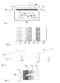
Fig. 1 ). As demonstrated inFig. 5 , for each time interval Δt, afraction 120" of the water volume in theconduit 110 is replaced with 'fresh', i.e. unheated water, at ambient temperature. The temperature within theconduit 110 thus decreases slightly according to the size (volume) of thefraction 120" at each interval Δt. The temperature of the water fraction 120' already present in theconduit 110 is estimated using equation 13:
whereas the temperature ofwater fraction 120" is estimated using equation 14:
- Equations 13 and 14 may be combined to provide an estimate of the average water temperature inside the
conduit 110 for a specific time step Δt, as shown in equation 15:
- The influx of
unheated water 120 via inlet 112 has the effect of reducing the average water temperature within theconduit 110 for each time step Δt. Equations 12-15 demonstrate that this model is capable of describing the water temperature at specific locations within theconduit 110 when subject to a water flow through theconduit 110 such that water passes through theconduit 110 in a plurality of time intervals Δt (i.e. more than one time interval Δt). - The system reaches equilibrium when the heat effectively transferred from the
heating element 130 to thewater 120 is equal to the heat loss by the flow of water, i.e. water volume, leaving theconduit 110 atoutlet 114 and the heat loss to theexternal surroundings 160. - The water temperature estimating algorithm may be further refined to take optional additional features of the
conduit 110 into consideration. For instance, theconduit 110 may include a spring coil within the water channel for the purpose of mixing the water as it travels through theconduit 110. Analysis of experimental results has demonstrated that this coil spring effectively alters the heat capacity of the water by a factor related to the occupied volume of the spring within theconduit 110. - The temperature estimating algorithm may factor in a percentage value for the volume of the spring within the water channel of the
conduit 110. In other words, the water channel volume is occupied by both water as well as the steel spring. Typically, the combined SHC of the spring and water is different to that of water alone. The SHC of the water channel can thus be adjusted to take into consideration the different mass and SHC of the steel spring within the water channel. - The combined SHC of water and spring can be calculated as shown in equation 16:

The loss-factor is also adjusted in calculating the energy in the water / spring medium as shown in equation 10.
It will be appreciated that other modifications to theconduit 110 may be modeled in a similar fashion. - The heat transfer model may be further refined by incorporating temperature sensors in the system of the present invention. The output of the temperature sensors may be used as calibration data for the heat transfer model. This is particularly useful in situations where the heat transfer model only approximates the real system, such as in situations where real-time changes to the system, such as ambient system temperature, cannot be accurately predicted. To this end, the temperature sensors take readings at predefined time intervals, such as every few seconds, with the temperature estimation program using these readings to recalibrate appropriate parameters in its heat transfer model. This way, it can be ensured that the heat transfer model accurately predicts the fluid temperature over prolonged periods of time.
- It will be appreciated that such a mixed system comprises distinct advantages over a system controlled by temperature sensors only, because the temperature estimation program provides a more accurate monitoring of rapid fluid temperature changes, with the relatively slow temperature sensors primarily being used to reduce or avoid drift in the calibration of the temperature estimation program.
- A fluid
temperature adjusting system 100 typically presents a relatively large load. Such loads can cause noticeable voltage variations on mains alternating current (AC) supply, which can lead to observable flicker in light sources connected to the AC mains. A known good design practice to limit the amount of flicker on the mains dictates that such a load is only switched on during a zero crossing of the mains AC cycle. Consequently, thetemperature adjusting element 130 can only be switched on or off every 10ms for a 50 Hz AC mains supply, or any other suitable frequency e.g. 60Hz. -
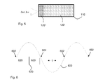
Fig. 6 shows a preferred embodiment of the duty cycle of thesystem 100 with respect to themains AC cycle 600 having zerocrossings 602. Theprocessor 140 is arranged to perform the temperature estimation of the fluid temperature in a selected location in theconduit 110 duringtime interval 620. Theprocessor 140 typically estimates the fluid temperature at the next zerocrossing 602. Upon completion of the estimation, as indicated byline 625, thecontroller 150 is provided with acontrol signal 146, which provides thecontroller 150 with an indication of the estimated temperature. Thecontroller 150 subsequently calculates the load to be applied to thetemperature adjusting element 130 at the next zerocrossing 602 as a function of thecontrol signal 146. This may be the determination of the amount of a variable load, or may be a binary switch on/off decision. - The
processor 140 should have sufficient computational power to ensure that thecontrol signal 146 is provided in time for thecontroller 150 to complete the calculation of the load before the arrival of the next zerocrossing 602. This may for instance be realized by using a high enddigital signal processor 140. - It should be noted that the above-mentioned embodiments illustrate rather than limit the invention, and that those skilled in the art will be able to design many alternative embodiments without departing from the scope of the appended claims. In the claims, any reference signs placed between parentheses shall not be construed as limiting the claim. The word "comprising" does not exclude the presence of elements or steps other than those listed in a claim. The word "a" or "an" preceding an element does not exclude the presence of a plurality of such elements. The mere fact that certain measures are recited in mutually different dependent claims does not indicate that a combination of these measures cannot be used to advantage.
Claims (31)
- A system (100) for changing the temperature (T1) of a fluid (120), comprising:an input (112) for receiving the fluid (120) at a first temperature (T1);an output (114) for delivering the fluid (120) at a second temperature (T2);a conduit (110) for transporting the fluid (120) from the input (112) to the output (114), the conduit (110) comprising means (130) for altering the temperature of the fluid from the first temperature (T1) to the second temperature (T2);a processor (140) comprising a temperature estimating program for estimating the fluid temperature in a selected location of the conduit (110) based on an estimate of the heat transfer between the fluid (120) and the conduit (110); anda controller (150) for providing a control signal to the temperature altering means (130) in response to the estimated fluid temperature.
- A system (100) as claimed in claim 1, wherein the program comprises a heat transfer model for estimating the heat transfer between the temperature altering means (130) and the fluid (120).
- A system (100) as claimed in claim 2, wherein program is arranged to estimate the heat transfer between the temperature altering means (130) and the fluid (120) using the most recent value of the control signal as an input variable.
- A system (100) as claimed in claim 2 or 3, wherein the temperature altering means (130) are located inside the conduit (110), and wherein the program is arranged to estimate the fluid temperature by including an estimate of the heat transfer between the fluid (120) and a medium (160) external to the conduit (110) through the conduit wall.
- A system (100) as claimed in claim 3, wherein the temperature adjusting means (130) comprise a multi-layered structure (132; 134) surrounding a temperature adjusting element (130), and wherein the program is arranged to estimate the heat transfer between the fluid (120) and the temperature adjusting means (130) by combining:- the estimated heat transfer between the temperature adjusting element (130) and an inner layer (132) of the multi-layered structure;- the estimated heat transfer between neighboring layers (132, 134) of the multi-layered structure; and- the estimated heat transfer between the outermost layer (134) of the multi-layered structure and the fluid (120).
- A system (100) as claimed in any of the preceding claims, wherein the program is arranged to use at least one fluid relating parameter selected from a group comprising the first temperature (T1) and flow rate of the fluid through the conduit as an input variable.
- A system (100) as claimed in any of claims 2-6, wherein the conduit (110) comprises mixing means for mixing the fluid (120), and wherein the program is arranged to calculate the heat transfer between the temperature adjusting means (130) and the combination of the fluid (120) and the mixing means.
- A system (100) as claimed in any of the preceding claims, wherein the temperature adjusting means (130) are arranged to be switched on or off during a zero crossing (602) of an alternating mains current (600), and wherein the processor (140) is arranged to provide to estimate the fluid temperature in a selected location in the conduit (110) and provide the controller (150) with said estimate in between two contiguous zero crossings (602).
- A system (100) as claimed in any of the preceding claims, wherein the program is arranged to estimate respective fluid temperatures in a plurality of locations of the conduit (110).
- A system (100) as claimed in any of the preceding claims, wherein the controller (150) is arranged to calculate a load for the temperature adjusting means (130) from the one or more temperatures estimated by the processor (140).
- A system (100) as claimed in any of the preceding claims, wherein the fluid (120) is water and the temperature adjusting means comprise a heating element (130).
- A system (100) as claimed in any of the preceding claims, wherein the heat transfer model is arranged to include heat loss.
- A system as claimed in any of the preceding claims, wherein the system comprises at least one temperature sensor for measuring the temperature of the fluid, the temperature sensor being arranged to provide the temperature estimation program with an output indicative of the measured temperature.
- A method for controlling a system for changing the temperature of a fluid (120), the system (100) comprising:an input (112) for receiving the fluid (120) at a first temperature (T1);an output (114) for delivering the fluid (120) at a second temperature (T2);a conduit (110) for transporting the fluid (120) from the input (112) to the output (114), the conduit (110) comprising means (130) for altering the temperature of the fluid (120) from the first temperature (T1) to the second temperature (T2); the method comprising:estimating the fluid temperature in a selected location of the conduit (110) by estimating the heat transfer between the fluid (120) and the conduit (110); andproviding a control signal to the temperature altering means (130) in response to the estimated fluid temperature.
- A method as claimed in claim 14, wherein the step of estimating the fluid temperature comprises estimating the heat transfer between the temperature altering means (130) and the fluid (120) using a heat transfer model.
- A method as claimed in claim 15, wherein the step of estimating the fluid temperature comprises estimating said temperature using the most recent value of the control signal as an input variable.
- A method as claimed in claim 15 or 16, wherein the temperature altering means (130) are located inside the conduit (110), and wherein the method further comprises estimating the fluid temperature by including the heat transfer between the fluid (120) and a medium (160) external to the conduit (110) through the conduit wall.
- A method as claimed in claim 15, wherein the temperature adjusting means (130) comprise a multi-layered structure (132; 134) surrounding a temperature adjusting element (130), and wherein the method comprises estimating the heat transfer between the temperature adjusting means (130) and the fluid (120) by:- estimating the heat transfer between the temperature adjusting element (130) and an inner layer (132) of the multi-layered structure;- estimating the heat transfer between neighboring layers (132, 134) of the multi-layered structure;- estimating the heat transfer between the outermost layer (134) of the multi-layered structure and the fluid (120); and- combining said estimations.
- A method as claimed in any of the claims 14-18, further comprising using at least one fluid relating parameter from a group comprising the first temperature (T1) and flow rate of the fluid (120) through the conduit (110) as an input variable for estimating said temperature.
- A method as claimed in any of claims 15-19, wherein the conduit (110) comprises mixing means for mixing the fluid, and wherein the method comprises calculating the heat transfer between the temperature adjusting means (130) and the combination of the fluid (120) and the mixing means.
- A method as claimed in any of claims 14-20, further comprising:switching the temperature adjusting means (130) during a zero crossing (602) of an alternating mains current (600); anda combined step of estimating the fluid temperature in a selected location of the conduit (110) and providing the controller (150) with said estimate during a time interval in between two contiguous zero crossings (602).
- A method as claimed in any of claims 14-21, further comprising estimating respective fluid temperatures in a plurality of locations of the conduit (110).
- A method as claimed in any of claims 14-22, further comprising calculating a load for the temperature adjusting means (130) from the one or more estimated temperatures.
- A method as claimed in any of claims 15-23, further comprising:measuring a temperature of the fluid inside the system;adjusting the heat transfer model based on the measured temperature.
- A computer-readable storage medium comprising a program for use with the system (100) of claim 1, the program comprising an algorithm for estimating the fluid temperature in a selected location of the conduit (110) based on an estimate of the heat transfer between the fluid (120) and the conduit (110).
- A computer-readable storage medium as claimed in claim 25, wherein the algorithm is arranged to estimate the heat transfer between the temperature altering means (130) and the fluid (120).
- A computer-readable storage medium as claimed in claim 25 or 26, wherein the algorithm is arranged to estimate said temperature using the most recent value of the control signal as an input variable.
- A computer-readable storage medium as claimed in any of claims 25-27, wherein the algorithm is arranged to estimate the fluid temperature by including the heat transfer between the fluid (120) and a medium (160) external to the conduit (110) through the conduit wall.
- A computer-readable storage medium as claimed in claim 28, wherein the temperature adjusting means (130) comprise a multi-layered structure (132; 134) surrounding a temperature adjusting element (130), and wherein the program is arranged to estimate the heat transfer between the fluid (120) and the temperature adjusting means (130) by combining:- the estimated heat transfer between the temperature adjusting element (130) and an inner layer (132) of the multi-layered structure;- the estimated heat transfer between neighboring layers (132, 134) of the multi-layered structure; and- the estimated heat transfer between the outer layer (134) of the multi-layered structure and the fluid (120).
- A computer-readable storage medium as claimed in any of claims 25-29, wherein the algorithm is arranged to estimate the heat transfer between the temperature adjusting means (130) and the combination of the fluid (120) and a mixing coil in the conduit (110).
- A computer-readable storage medium as claimed in any of claims 25-30, wherein the program is arranged to estimate respective fluid temperatures in a plurality of locations of the conduit (110).
Priority Applications (5)
| Application Number | Priority Date | Filing Date | Title |
|---|---|---|---|
| EP08150779A EP2085715A1 (en) | 2008-01-29 | 2008-01-29 | System for changing fluid temperature and method for controlling such a system |
| JP2009011247A JP5355106B2 (en) | 2008-01-29 | 2009-01-21 | System for changing fluid temperature and method for controlling such a system |
| US12/360,603 US8118482B2 (en) | 2008-01-29 | 2009-01-27 | System for changing fluid temperature and method for controlling such a system |
| CA002651443A CA2651443A1 (en) | 2008-01-29 | 2009-01-28 | System for changing fluid temperature and method for controlling such a system |
| CNA2009100032783A CN101498943A (en) | 2008-01-29 | 2009-02-01 | System for changing fluid temperature and method for controlling such a system |
Applications Claiming Priority (1)
| Application Number | Priority Date | Filing Date | Title |
|---|---|---|---|
| EP08150779A EP2085715A1 (en) | 2008-01-29 | 2008-01-29 | System for changing fluid temperature and method for controlling such a system |
Publications (1)
| Publication Number | Publication Date |
|---|---|
| EP2085715A1 true EP2085715A1 (en) | 2009-08-05 |
Family
ID=39563370
Family Applications (1)
| Application Number | Title | Priority Date | Filing Date |
|---|---|---|---|
| EP08150779A Withdrawn EP2085715A1 (en) | 2008-01-29 | 2008-01-29 | System for changing fluid temperature and method for controlling such a system |
Country Status (5)
| Country | Link |
|---|---|
| US (1) | US8118482B2 (en) |
| EP (1) | EP2085715A1 (en) |
| JP (1) | JP5355106B2 (en) |
| CN (1) | CN101498943A (en) |
| CA (1) | CA2651443A1 (en) |
Families Citing this family (9)
| Publication number | Priority date | Publication date | Assignee | Title |
|---|---|---|---|---|
| US8770152B2 (en) * | 2008-10-21 | 2014-07-08 | Honeywell International Inc. | Water Heater with partially thermally isolated temperature sensor |
| WO2011106024A1 (en) * | 2010-02-26 | 2011-09-01 | Hewlett-Packard Development Company, L.P. | Flow measurement system and methods |
| WO2013154534A1 (en) * | 2012-04-10 | 2013-10-17 | Deere & Company | Piezoelectric control system |
| CN103558881B (en) * | 2013-11-11 | 2016-01-27 | 深圳市理邦精密仪器股份有限公司 | A kind of method and device heating blood in testing pipes |
| US9704329B2 (en) * | 2014-05-01 | 2017-07-11 | Elkay Manufacturing Company | System and method for dispensing consumable liquids |
| CN107949078B (en) * | 2018-01-09 | 2024-05-14 | 广东环葆嘉节能科技有限公司 | Moving medium double-heating control device |
| CN109084477B (en) * | 2018-08-23 | 2024-02-23 | 芜湖美的厨卫电器制造有限公司 | Phase-change water heater |
| RU2770168C1 (en) * | 2018-09-28 | 2022-04-14 | Роузмаунт Инк. | Non-invasive indication of the temperature of the process medium with reduced error |
| CN111256288B (en) * | 2020-01-21 | 2021-11-02 | 海信(广东)空调有限公司 | Refrigerant temperature and refrigerant leak detection method for compressor and air conditioner |
Citations (5)
| Publication number | Priority date | Publication date | Assignee | Title |
|---|---|---|---|---|
| WO1993004421A1 (en) | 1991-08-13 | 1993-03-04 | Sous Chef Limited | Temperature control in an ohmic process |
| EP0654724A1 (en) | 1993-11-19 | 1995-05-24 | Electricite De France | Device and method for electric fluid heating in an electric-resistance pipe |
| DE19531134A1 (en) | 1995-08-24 | 1997-02-27 | Forbach Gmbh | Electrical through-flow water heater with several separate adjustable heating stages |
| WO1999038356A1 (en) | 1998-01-23 | 1999-07-29 | Lufran Incorporated | Demand anticipation control system for a high efficiency ultra-pure fluid heater |
| WO2004034742A1 (en) * | 2002-10-10 | 2004-04-22 | Irca S.P.A. | Improvement in a through-flow fluid heater tube |
Family Cites Families (11)
| Publication number | Priority date | Publication date | Assignee | Title |
|---|---|---|---|---|
| JPS5956040A (en) * | 1982-09-22 | 1984-03-31 | Mitsubishi Electric Corp | Tap controlled type hot-water supplying apparatus |
| DE3544411A1 (en) * | 1985-12-16 | 1987-06-19 | Honeywell Bv | HOT WATER HEATING SYSTEM WITH HEAT CONSUMER |
| JPH0820112B2 (en) * | 1991-07-08 | 1996-03-04 | 阪神エレクトリック株式会社 | Hot water temperature control method for automatic hot water supply system |
| JP3579440B2 (en) * | 1993-09-01 | 2004-10-20 | 株式会社ガスター | Self-check method of temperature sensor in large capacity hot water supply system with combined heat source |
| US5504306A (en) * | 1994-07-25 | 1996-04-02 | Chronomite Laboratories, Inc. | Microprocessor controlled tankless water heater system |
| JP3644354B2 (en) * | 2000-05-09 | 2005-04-27 | トヨタ自動車株式会社 | Temperature estimation method and apparatus |
| US6539173B2 (en) | 2001-05-02 | 2003-03-25 | Dynamo Aviation, Inc. | Sensor controlled water heater and method of use |
| JP2004069667A (en) * | 2002-06-12 | 2004-03-04 | Yokogawa Electric Corp | Thermal mass flow meter for liquid |
| US7225629B2 (en) * | 2004-01-20 | 2007-06-05 | Carrier Corporation | Energy-efficient heat pump water heater |
| US7945146B2 (en) * | 2007-06-07 | 2011-05-17 | Ecosmart Us Llc | Tankless hot water heater with power modulation |
| US20110135289A1 (en) * | 2009-12-08 | 2011-06-09 | Kayser Kenneth W | Water heating system with point-of-use control |
-
2008
- 2008-01-29 EP EP08150779A patent/EP2085715A1/en not_active Withdrawn
-
2009
- 2009-01-21 JP JP2009011247A patent/JP5355106B2/en not_active Expired - Fee Related
- 2009-01-27 US US12/360,603 patent/US8118482B2/en not_active Expired - Fee Related
- 2009-01-28 CA CA002651443A patent/CA2651443A1/en not_active Abandoned
- 2009-02-01 CN CNA2009100032783A patent/CN101498943A/en active Pending
Patent Citations (5)
| Publication number | Priority date | Publication date | Assignee | Title |
|---|---|---|---|---|
| WO1993004421A1 (en) | 1991-08-13 | 1993-03-04 | Sous Chef Limited | Temperature control in an ohmic process |
| EP0654724A1 (en) | 1993-11-19 | 1995-05-24 | Electricite De France | Device and method for electric fluid heating in an electric-resistance pipe |
| DE19531134A1 (en) | 1995-08-24 | 1997-02-27 | Forbach Gmbh | Electrical through-flow water heater with several separate adjustable heating stages |
| WO1999038356A1 (en) | 1998-01-23 | 1999-07-29 | Lufran Incorporated | Demand anticipation control system for a high efficiency ultra-pure fluid heater |
| WO2004034742A1 (en) * | 2002-10-10 | 2004-04-22 | Irca S.P.A. | Improvement in a through-flow fluid heater tube |
Also Published As
| Publication number | Publication date |
|---|---|
| US8118482B2 (en) | 2012-02-21 |
| JP2009180496A (en) | 2009-08-13 |
| JP5355106B2 (en) | 2013-11-27 |
| US20090192748A1 (en) | 2009-07-30 |
| CN101498943A (en) | 2009-08-05 |
| CA2651443A1 (en) | 2009-07-29 |
Similar Documents
| Publication | Publication Date | Title |
|---|---|---|
| EP2085715A1 (en) | System for changing fluid temperature and method for controlling such a system | |
| JP5735639B2 (en) | Temperature estimation | |
| Weinläder et al. | PCM cooling ceilings in the Energy Efficiency Center—passive cooling potential of two different system designs | |
| Cholewa et al. | On the heat transfer coefficients between heated/cooled radiant ceiling and room | |
| CN112484230B (en) | Device and method for controlling comfort temperature of air conditioning equipment or air conditioning system | |
| Koo et al. | Effects of wallboard design parameters on the thermal storage in buildings | |
| US10378805B2 (en) | Model predictive control for heat transfer to fluids | |
| KR102368854B1 (en) | Method and device for determining the heat loss coefficient of a room | |
| US20110211612A1 (en) | Temperature sensor array and method of analyzing a condition of water in a tank of a water heating system | |
| US9448193B2 (en) | Method and device for determining the heat loss coefficient of a premises | |
| CA2868478C (en) | Thermal storage device | |
| AU2016214236A1 (en) | Determination of the thermal resistance of a wall | |
| De Gracia et al. | A simple model to predict the thermal performance of a ventilated facade with phase change materials | |
| JP6240900B2 (en) | HEAT PUMP CONTROL DEVICE AND HEAT PUMP CONTROL DEVICE CONTROL METHOD | |
| GB2518365A (en) | Apparatus and method for volumetric estimation of heated water | |
| Vián et al. | Development of a hybrid refrigerator combining thermoelectric and vapor compression technologies | |
| EP3279579B1 (en) | Air-conditioning system control device | |
| Basak et al. | Performance evaluation of material and comparison of different temperature control strategies of a Guarded Hot Box U-value Test Facility | |
| Rodríguez et al. | Development and experimental validation of a computational model in order to simulate ice cube production in a thermoelectric ice-maker | |
| JP7128958B2 (en) | How to control hair care appliances | |
| JP2019120531A (en) | Thermophysical property measuring apparatus and thermophysical property measuring method | |
| Antypov et al. | Analysis of the Influence of the Internal Heat Capacity of a Public Building on the Thermal Comfort Parameters of the Premises During the Operation of the Heating System in Alternating Mode. | |
| JP2006038387A (en) | Regenerative floor heating device | |
| Abramchuk et al. | Dynamic method for measuring thermal characteristics of heating devices | |
| JPH0876858A (en) | Heat source control system |
Legal Events
| Date | Code | Title | Description |
|---|---|---|---|
| PUAI | Public reference made under article 153(3) epc to a published international application that has entered the european phase |
Free format text: ORIGINAL CODE: 0009012 |
|
| 17P | Request for examination filed |
Effective date: 20080130 |
|
| AK | Designated contracting states |
Kind code of ref document: A1 Designated state(s): AT BE BG CH CY CZ DE DK EE ES FI FR GB GR HR HU IE IS IT LI LT LU LV MC MT NL NO PL PT RO SE SI SK TR |
|
| AX | Request for extension of the european patent |
Extension state: AL BA MK RS |
|
| AKX | Designation fees paid |
Designated state(s): AT BE BG CH CY CZ DE DK EE ES FI FR GB GR HR HU IE IS IT LI LT LU LV MC MT NL NO PL PT RO SE SI SK TR |
|
| REG | Reference to a national code |
Ref country code: HK Ref legal event code: DE Ref document number: 1135757 Country of ref document: HK |
|
| STAA | Information on the status of an ep patent application or granted ep patent |
Free format text: STATUS: THE APPLICATION HAS BEEN WITHDRAWN |
|
| 18W | Application withdrawn |
Effective date: 20140214 |
|
| REG | Reference to a national code |
Ref country code: HK Ref legal event code: WD Ref document number: 1135757 Country of ref document: HK |