EP2085681A2 - Dispositif d'éclairage à DEL, module de source lumineuse à DEL, et élément de support à DEL - Google Patents
Dispositif d'éclairage à DEL, module de source lumineuse à DEL, et élément de support à DEL Download PDFInfo
- Publication number
- EP2085681A2 EP2085681A2 EP09151178A EP09151178A EP2085681A2 EP 2085681 A2 EP2085681 A2 EP 2085681A2 EP 09151178 A EP09151178 A EP 09151178A EP 09151178 A EP09151178 A EP 09151178A EP 2085681 A2 EP2085681 A2 EP 2085681A2
- Authority
- EP
- European Patent Office
- Prior art keywords
- foam
- led
- metal
- layer
- foam metal
- Prior art date
- Legal status (The legal status is an assumption and is not a legal conclusion. Google has not performed a legal analysis and makes no representation as to the accuracy of the status listed.)
- Withdrawn
Links
Images


Classifications
-
- F—MECHANICAL ENGINEERING; LIGHTING; HEATING; WEAPONS; BLASTING
- F21—LIGHTING
- F21V—FUNCTIONAL FEATURES OR DETAILS OF LIGHTING DEVICES OR SYSTEMS THEREOF; STRUCTURAL COMBINATIONS OF LIGHTING DEVICES WITH OTHER ARTICLES, NOT OTHERWISE PROVIDED FOR
- F21V29/00—Protecting lighting devices from thermal damage; Cooling or heating arrangements specially adapted for lighting devices or systems
- F21V29/85—Protecting lighting devices from thermal damage; Cooling or heating arrangements specially adapted for lighting devices or systems characterised by the material
- F21V29/89—Metals
-
- F—MECHANICAL ENGINEERING; LIGHTING; HEATING; WEAPONS; BLASTING
- F21—LIGHTING
- F21K—NON-ELECTRIC LIGHT SOURCES USING LUMINESCENCE; LIGHT SOURCES USING ELECTROCHEMILUMINESCENCE; LIGHT SOURCES USING CHARGES OF COMBUSTIBLE MATERIAL; LIGHT SOURCES USING SEMICONDUCTOR DEVICES AS LIGHT-GENERATING ELEMENTS; LIGHT SOURCES NOT OTHERWISE PROVIDED FOR
- F21K9/00—Light sources using semiconductor devices as light-generating elements, e.g. using light-emitting diodes [LED] or lasers
- F21K9/60—Optical arrangements integrated in the light source, e.g. for improving the colour rendering index or the light extraction
-
- F—MECHANICAL ENGINEERING; LIGHTING; HEATING; WEAPONS; BLASTING
- F21—LIGHTING
- F21S—NON-PORTABLE LIGHTING DEVICES; SYSTEMS THEREOF; VEHICLE LIGHTING DEVICES SPECIALLY ADAPTED FOR VEHICLE EXTERIORS
- F21S2/00—Systems of lighting devices, not provided for in main groups F21S4/00 - F21S10/00 or F21S19/00, e.g. of modular construction
- F21S2/005—Systems of lighting devices, not provided for in main groups F21S4/00 - F21S10/00 or F21S19/00, e.g. of modular construction of modular construction
-
- F—MECHANICAL ENGINEERING; LIGHTING; HEATING; WEAPONS; BLASTING
- F21—LIGHTING
- F21V—FUNCTIONAL FEATURES OR DETAILS OF LIGHTING DEVICES OR SYSTEMS THEREOF; STRUCTURAL COMBINATIONS OF LIGHTING DEVICES WITH OTHER ARTICLES, NOT OTHERWISE PROVIDED FOR
- F21V29/00—Protecting lighting devices from thermal damage; Cooling or heating arrangements specially adapted for lighting devices or systems
- F21V29/50—Cooling arrangements
- F21V29/60—Cooling arrangements characterised by the use of a forced flow of gas, e.g. air
- F21V29/67—Cooling arrangements characterised by the use of a forced flow of gas, e.g. air characterised by the arrangement of fans
-
- F—MECHANICAL ENGINEERING; LIGHTING; HEATING; WEAPONS; BLASTING
- F21—LIGHTING
- F21V—FUNCTIONAL FEATURES OR DETAILS OF LIGHTING DEVICES OR SYSTEMS THEREOF; STRUCTURAL COMBINATIONS OF LIGHTING DEVICES WITH OTHER ARTICLES, NOT OTHERWISE PROVIDED FOR
- F21V29/00—Protecting lighting devices from thermal damage; Cooling or heating arrangements specially adapted for lighting devices or systems
- F21V29/50—Cooling arrangements
- F21V29/70—Cooling arrangements characterised by passive heat-dissipating elements, e.g. heat-sinks
- F21V29/74—Cooling arrangements characterised by passive heat-dissipating elements, e.g. heat-sinks with fins or blades
-
- F—MECHANICAL ENGINEERING; LIGHTING; HEATING; WEAPONS; BLASTING
- F21—LIGHTING
- F21V—FUNCTIONAL FEATURES OR DETAILS OF LIGHTING DEVICES OR SYSTEMS THEREOF; STRUCTURAL COMBINATIONS OF LIGHTING DEVICES WITH OTHER ARTICLES, NOT OTHERWISE PROVIDED FOR
- F21V29/00—Protecting lighting devices from thermal damage; Cooling or heating arrangements specially adapted for lighting devices or systems
- F21V29/85—Protecting lighting devices from thermal damage; Cooling or heating arrangements specially adapted for lighting devices or systems characterised by the material
-
- F—MECHANICAL ENGINEERING; LIGHTING; HEATING; WEAPONS; BLASTING
- F21—LIGHTING
- F21K—NON-ELECTRIC LIGHT SOURCES USING LUMINESCENCE; LIGHT SOURCES USING ELECTROCHEMILUMINESCENCE; LIGHT SOURCES USING CHARGES OF COMBUSTIBLE MATERIAL; LIGHT SOURCES USING SEMICONDUCTOR DEVICES AS LIGHT-GENERATING ELEMENTS; LIGHT SOURCES NOT OTHERWISE PROVIDED FOR
- F21K9/00—Light sources using semiconductor devices as light-generating elements, e.g. using light-emitting diodes [LED] or lasers
-
- F—MECHANICAL ENGINEERING; LIGHTING; HEATING; WEAPONS; BLASTING
- F21—LIGHTING
- F21Y—INDEXING SCHEME ASSOCIATED WITH SUBCLASSES F21K, F21L, F21S and F21V, RELATING TO THE FORM OR THE KIND OF THE LIGHT SOURCES OR OF THE COLOUR OF THE LIGHT EMITTED
- F21Y2115/00—Light-generating elements of semiconductor light sources
- F21Y2115/10—Light-emitting diodes [LED]
Definitions
- the present invention relates to a light emitting diode (LED) illuminating structure, and more particularly to a LED illuminating device, a LED light source module, and a LED support member.
- LED light emitting diode
- LED light emitting diode
- LED illuminating devices is a LED light source module having a plurality of LEDs installed on an aluminum (Al) substrate and arranged according to a predetermined manner, wherein the Al substrate is used to dissipate heat generated by the LEDs.
- Al substrate is used to dissipate heat generated by the LEDs.
- the thickness of the Al substrate must be increased.
- the weight of the entire LED illuminating device may be inevitably increased, the operational convenience thereof may be lowered, and the manufacture cost thereof may be increased.
- the foregoing shortcomings of high-power LED illuminating devices are apparent.
- a high-power LED street lamp of 120 watts which is provided with a Al substrate for dissipating heat, has a weight about 9kg, wherein most of the weight is due to the thickness and height of the Al substrate increased for heat-dissipating purpose.
- the weight of the entire street lamp is substantially increased, so that the installation and disassembly thereof is inconvenient and the material cost thereof is increased.
- the Al substrate has too large integrated heat sinks, the demand of cast molds for the Al substrate may be increased. Meanwhile, the product yield thereof may be lowered, and the manufacture cost thereof may be substantially increased.
- the heat-dissipation efficiency of the entire street lamp can not be enhanced to an ideal value.
- a primary object of the present invention is to provide a LED illuminating device, which includes a housing and a LED light source module which has a plurality of LEDs and a LED support member.
- the LEDs are installed on the LED support member which is provided with a foam metal layer and a metal support layer having at least one portion for supporting the LEDs.
- the foam metal layer is made of foam metal having porous structures, the metal support layer is formed on a portion of a surface of the foam metal layer, and the metal support layer and the foam metal layer are connected to each other.
- a secondary object of the present invention is to provide a LED light source module, which includes a plurality of LEDs and a LED support member.
- the LEDs are installed on the LED support member which is provided with a foam metal layer and a metal support layer having at least one portion for supporting the LEDs.
- the foam metal layer is made of foam metal having porous structures, the metal support layer is formed on a portion of a surface of the foam metal layer, and the metal support layer and the foam metal layer are connected to each other.
- a third object of the present invention is to provide a LED support member, which is used to support a plurality of LEDs.
- the LED support member includes a foam metal layer and a metal support layer having at least one portion for supporting the LEDs.
- the foam metal layer is made of foam metal having porous structures, the metal support layer is formed on a portion of a surface of the foam metal layer, and the metal support layer and the foam metal layer are connected to each other.
- the foam metal is foam iron, foam copper, foam aluminum, foam iron alloy, foam copper alloy, or foam aluminum alloy.
- the foam metal has 10-50 micro-pores per inch.
- the metal support layer is a solid metal layer made of the same metal material as the foam metal.
- a cooling fan is mounted on a surface of the foam metal layer different from the surface thereof formed with the metal support layer or received in a receiving space defined by the foam metal layer.
- remaining surfaces of the foam metal layer different from the surface thereof formed with the metal support layer has at least one covered portion.
- the metal support layer is connected to the foam metal layer by electro-plating.
- the LED support member of the LED illuminating device according to the present invention is improved, wherein the surface of the foam metal layer is formed with the metal support layer, and the LEDs are installed on the metal support layer through a printed circuit board.
- the heat generated by the LEDs is speedily transmitted to the foam metal layer through the metal support layer.
- the foam metal layer provides 3-dimensional webbed structures therein, so as to substantially increase surface area of the foam metal layer for being in contact with external air.
- the heat-dissipation efficiency can be improved.
- the foam metal layer made of foam metal is advantageous to save considerable metal material, so as to substantially lower the weight of the entire LED illuminating device and the manufacture cost thereof, and enhance the convenience thereof.
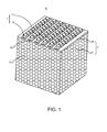
- Fig. 1 is an assembled perspective view of a LED light source module in a LED illuminating device according to a first embodiment of the present invention
- Fig. 2 is an assembled perspective view of a LED light source module in a LED illuminating device according to a second embodiment of the present invention
- Fig. 3 is another perspective view of the LED light source module in the LED illuminating device, as shown in Fig. 2 ;
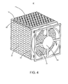
- Fig. 4 is an assembled perspective view of a LED light source module in a LED illuminating device according to a third embodiment of the present invention.
- Fig. 5 is an assembled perspective view of a LED light source module in a LED illuminating device according to a fourth embodiment of the present invention.
- Fig. 6 is an assembled perspective view of a LED light source module in a LED illuminating device according to a fifth embodiment of the present invention.
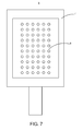
- Fig. 7 is a schematic view of the LED illuminating device according to the first embodiment of the present invention.
- the LED illuminating device 9 comprises a housing 7 and a LED light source module 8 which has a LED light source 1 and a LED support member 2.
- the LED light source 1 comprises a plurality of LEDs (not-shown) and a plurality of printed circuit boards 10 made of high thermal conductive material (such as aluminum) for supporting the LEDs.
- the LEDs are arranged on each of the printed circuit boards 10 to define a plurality of LED illuminating strips (unlabeled).
- each of the LEDs can be provided with a lens means 11 according to an actual desire.
- the LED support member 2 comprises a foam metal layer 21 and a metal support layer 20 having at least one portion for supporting the LEDs.
- the foam metal layer 21 is made of foam metal having porous structures, such as foam iron, foam copper, foam aluminum, foam iron alloy, foam copper alloy, foam aluminum alloy, and etc, wherein the foam metal has about 10-50 micro-pores per inch.
- the foam metal layer 21 is made of foam copper
- the metal support layer 20 is formed on a portion of a surface of the foam metal layer 21.
- the metal support layer 20 is a solid metal layer made of the same metal material as the foam metal.
- the foam metal layer 21 is made of foam copper
- the metal support layer 20 is a solid metal layer made of copper.
- the metal support layer 20 and the foam metal layer 21 are connected to each other.
- the metal support layer 20 is connected to the foam metal layer 21 by electro-plating.
- the LEDs are mounted on the LED support member 2 through the printed circuit board 10.
- the LEDs are mounted on the metal support layer 20 through the printed circuit board 10 which is tightly in contact with the metal support layer 20 to increase the surface area therebetween.
- a thermal conductive material (such as a thermal conductive adhesive) can be optionally disposed between the printed circuit board 10 and the metal support layer 20.
- the foam metal layer 21 provides 3-dimensional webbed structures therein, so as to substantially increase surface area of the foam metal layer 21 for being in contact with external air.
- the heat-dissipation efficiency can be improved.
- the foam metal layer 21 made of foam metal is advantageous to save considerable metal material, so as to substantially lower the weight of the entire LED illuminating device 9 and the manufacture cost thereof, and enhance the convenience thereof.
- the LED illuminating device of the second embodiment comprises a LED light source module 8' different from that of the first embodiment.
- the LED light source module 8' has a LED support member 2 which is further provided with a cooling fan 23.
- the cooling fan 23 is mounted on a surface of the foam metal layer 21 different from the surface thereof formed with the metal support layer 20.
- the cooling fan 23 is mounted on a surface of the foam metal layer 21 opposite to the surface formed with the metal support layer 20.
- the cooling fan 23 rotates, and the foam metal layer 21 made of foam metal having porous structures can provide 3-dimensional webbed structures and micro-pores therein.
- the foam metal layer 21 made of foam metal having porous structures can provide 3-dimensional webbed structures and micro-pores therein.
- the LED illuminating device of the third embodiment comprises a LED light source module 8" different from that of the second embodiment.
- the LED light source module 8" is provided with a cooling fan 23.
- the cooling fan 23 is mounted on a side surface of the foam metal layer 21 adjacent to the surface thereof formed with the metal support layer 20.
- the operational principle of the LED illuminating device of the third embodiment is similar to that of the second embodiment, so that the description thereof will be omitted hereinafter.
- the LED illuminating device of the fourth embodiment comprises a LED light source module 8"' different from that of the first embodiment.
- the LED light source module 8"' has a foam metal layer 21 which has a side surface covered by a thermal insulation plate 25.
- the thermal insulation plate 25 covers a desired side surface of the foam metal layer 21 according to an actual position of a heat source and a possible position of a cooling fan 23, so as to provide a better heat-dissipation efficiency and efficiently solve the problem of partial concentration of the heat source.
- the covered side surface of the foam metal layer 21 is determined according to the actual position of the heat source. For example, a side surface of the foam metal layer 21 which the heat source is close to may keep open, while the remaining side surfaces thereof are covered by the thermal insulation plate 25.
- the cooling fan 23 operates, air mainly flows through the side surface of the foam metal layer 21 where the heat source is close to, so as to efficiently solve the problem of partial concentration of the heat source.
- the LED illuminating device of the fifth embodiment comprises a LED light source module 8"" different from that of the first embodiment.
- the LED light source module 8"" has a cooling fan 23 received in a receiving space (unlabeled) defined by a foam metal layer 21.
- the operational principle of the LED illuminating device of the fifth embodiment is similar to that of the second embodiment, so that the description thereof will be omitted hereinafter.
Applications Claiming Priority (1)
| Application Number | Priority Date | Filing Date | Title |
|---|---|---|---|
| CNA2008100333273A CN101220934A (zh) | 2008-01-31 | 2008-01-31 | Led照明装置 |
Publications (1)
| Publication Number | Publication Date |
|---|---|
| EP2085681A2 true EP2085681A2 (fr) | 2009-08-05 |
Family
ID=39630932
Family Applications (1)
| Application Number | Title | Priority Date | Filing Date |
|---|---|---|---|
| EP09151178A Withdrawn EP2085681A2 (fr) | 2008-01-31 | 2009-01-23 | Dispositif d'éclairage à DEL, module de source lumineuse à DEL, et élément de support à DEL |
Country Status (4)
| Country | Link |
|---|---|
| EP (1) | EP2085681A2 (fr) |
| JP (1) | JP2009182327A (fr) |
| KR (1) | KR20090084689A (fr) |
| CN (1) | CN101220934A (fr) |
Cited By (3)
| Publication number | Priority date | Publication date | Assignee | Title |
|---|---|---|---|---|
| EP2400252A1 (fr) * | 2010-06-24 | 2011-12-28 | Valeo Vision | Dispositif à échange de chaleur, notamment pour véhicule automobile |
| FR2965042A1 (fr) * | 2010-09-22 | 2012-03-23 | Valeo Vision | Dispositif a echange de chaleur, notamment pour vehicule automobile |
| US10378750B2 (en) * | 2015-01-12 | 2019-08-13 | Xyzed | Lighting module with diodes having improved cooling |
Families Citing this family (6)
| Publication number | Priority date | Publication date | Assignee | Title |
|---|---|---|---|---|
| JP5574671B2 (ja) * | 2009-11-05 | 2014-08-20 | キヤノン株式会社 | Usbホスト装置、制御方法、及びプログラム |
| CN102661505A (zh) * | 2012-05-02 | 2012-09-12 | 浙江全加好科技有限公司 | 一种设有金属散热装置的大功率led平板灯具 |
| CN102661504A (zh) * | 2012-05-02 | 2012-09-12 | 浙江全加好科技有限公司 | 一种设有金属散热装置的大功率led筒灯 |
| CN104315486A (zh) * | 2013-04-20 | 2015-01-28 | 大连三维传热技术有限公司 | SiO2纳米液体工质的泡沫金属吸液芯热板散热器 |
| CN103727506A (zh) * | 2013-12-13 | 2014-04-16 | 青岛威力电子科技有限公司 | Led光源承载体的高效散热方法 |
| CN105177339B (zh) * | 2015-10-26 | 2016-12-07 | 三峡大学 | 一种三维空间有序孔结构泡沫铝及其制备方法 |
Family Cites Families (2)
| Publication number | Priority date | Publication date | Assignee | Title |
|---|---|---|---|---|
| GB2404009B (en) * | 2003-07-17 | 2005-06-15 | Enfis Ltd | Cooling method and apparatus |
| US9412926B2 (en) * | 2005-06-10 | 2016-08-09 | Cree, Inc. | High power solid-state lamp |
-
2008
- 2008-01-31 CN CNA2008100333273A patent/CN101220934A/zh active Pending
-
2009
- 2009-01-22 KR KR1020090005409A patent/KR20090084689A/ko not_active Application Discontinuation
- 2009-01-23 JP JP2009012664A patent/JP2009182327A/ja active Pending
- 2009-01-23 EP EP09151178A patent/EP2085681A2/fr not_active Withdrawn
Cited By (6)
| Publication number | Priority date | Publication date | Assignee | Title |
|---|---|---|---|---|
| EP2400252A1 (fr) * | 2010-06-24 | 2011-12-28 | Valeo Vision | Dispositif à échange de chaleur, notamment pour véhicule automobile |
| FR2961894A1 (fr) * | 2010-06-24 | 2011-12-30 | Valeo Vision | Dispositif a echange de chaleur, notamment pour vehicule automobile |
| US9103605B2 (en) | 2010-06-24 | 2015-08-11 | Valeo Vision | Heat exchange device |
| FR2965042A1 (fr) * | 2010-09-22 | 2012-03-23 | Valeo Vision | Dispositif a echange de chaleur, notamment pour vehicule automobile |
| EP2434246A1 (fr) * | 2010-09-22 | 2012-03-28 | Valeo Vision | Dispositif à échange de chaleur, notamment pour véhicule automobile |
| US10378750B2 (en) * | 2015-01-12 | 2019-08-13 | Xyzed | Lighting module with diodes having improved cooling |
Also Published As
| Publication number | Publication date |
|---|---|
| JP2009182327A (ja) | 2009-08-13 |
| KR20090084689A (ko) | 2009-08-05 |
| CN101220934A (zh) | 2008-07-16 |
Similar Documents
| Publication | Publication Date | Title |
|---|---|---|
| EP2085681A2 (fr) | Dispositif d'éclairage à DEL, module de source lumineuse à DEL, et élément de support à DEL | |
| US7699501B2 (en) | LED illuminating device and light engine thereof | |
| EP2192346A2 (fr) | Arrangement de dissipation thermique pour DEL | |
| US20090016062A1 (en) | Led lamp | |
| US20080149305A1 (en) | Heat Sink Structure for High Power LED Lamp | |
| KR20080002564U (ko) | 발광 다이오드 모듈을 구비한 조명장치 | |
| JP2014135350A (ja) | ヒートシンク | |
| KR101033989B1 (ko) | 경금속계열 합금의 방열구조를 갖는 파워 발광다이오드형 도로 조명기구 | |
| CN101220935A (zh) | Led光源承载体 | |
| US9541275B2 (en) | Apparatus and method for management of heat in a LED mounted lighting fixture | |
| KR101294943B1 (ko) | 방열구조를 가지는 인쇄회로기판 및 이를 포함하는 led 조명장치 | |
| CN101220946A (zh) | 改善led光源模组散热效果的方法 | |
| CN201170510Y (zh) | Led照明装置 | |
| JP3163777U (ja) | ヒートシンクおよびledランプ | |
| KR20160033952A (ko) | 조명장치 | |
| KR102419835B1 (ko) | 방열성을 극대화하여 우수한 발광효율을 갖는 엘이디 조명등 | |
| TWI360620B (en) | Led lamp | |
| CN202327758U (zh) | 一种led光源组件 | |
| KR20110024214A (ko) | 우수한 광량을 갖는 led 조명등 | |
| TWI420040B (zh) | 發光二極體燈具 | |
| CN103727499A (zh) | Led光源承载体的高效散热装置 | |
| CN201170513Y (zh) | Led光源模组 | |
| CN201170511Y (zh) | Led光源模组 | |
| CN201170512Y (zh) | Led照明装置 | |
| CN101220932A (zh) | Led光源模组 |
Legal Events
| Date | Code | Title | Description |
|---|---|---|---|
| PUAI | Public reference made under article 153(3) epc to a published international application that has entered the european phase |
Free format text: ORIGINAL CODE: 0009012 |
|
| AK | Designated contracting states |
Kind code of ref document: A2 Designated state(s): AT BE BG CH CY CZ DE DK EE ES FI FR GB GR HR HU IE IS IT LI LT LU LV MC MK MT NL NO PL PT RO SE SI SK TR |
|
| AX | Request for extension of the european patent |
Extension state: AL BA RS |
|
| STAA | Information on the status of an ep patent application or granted ep patent |
Free format text: STATUS: THE APPLICATION IS DEEMED TO BE WITHDRAWN |
|
| 18D | Application deemed to be withdrawn |
Effective date: 20110803 |