EP2085577A1 - Method for the start-up of a gas turbine - Google Patents
Method for the start-up of a gas turbine Download PDFInfo
- Publication number
- EP2085577A1 EP2085577A1 EP09151772A EP09151772A EP2085577A1 EP 2085577 A1 EP2085577 A1 EP 2085577A1 EP 09151772 A EP09151772 A EP 09151772A EP 09151772 A EP09151772 A EP 09151772A EP 2085577 A1 EP2085577 A1 EP 2085577A1
- Authority
- EP
- European Patent Office
- Prior art keywords
- turbine
- combustor
- fuel
- ignition
- fsr
- Prior art date
- Legal status (The legal status is an assumption and is not a legal conclusion. Google has not performed a legal analysis and makes no representation as to the accuracy of the status listed.)
- Granted
Links
- 238000000034 method Methods 0.000 title claims abstract description 27
- 239000000446 fuel Substances 0.000 claims abstract description 56
- 238000010926 purge Methods 0.000 claims abstract description 20
- 239000000203 mixture Substances 0.000 claims abstract description 18
- 239000007789 gas Substances 0.000 description 33
- 238000010586 diagram Methods 0.000 description 6
- 238000002485 combustion reaction Methods 0.000 description 4
- 239000002737 fuel gas Substances 0.000 description 4
- 230000003213 activating effect Effects 0.000 description 3
- 230000007423 decrease Effects 0.000 description 3
- 238000010438 heat treatment Methods 0.000 description 2
- 230000001133 acceleration Effects 0.000 description 1
- 230000004913 activation Effects 0.000 description 1
- 238000004140 cleaning Methods 0.000 description 1
- 230000006835 compression Effects 0.000 description 1
- 238000007906 compression Methods 0.000 description 1
- 230000001276 controlling effect Effects 0.000 description 1
- 230000002596 correlated effect Effects 0.000 description 1
- 230000001419 dependent effect Effects 0.000 description 1
- 238000004880 explosion Methods 0.000 description 1
- 230000005484 gravity Effects 0.000 description 1
- 238000002955 isolation Methods 0.000 description 1
- 238000004519 manufacturing process Methods 0.000 description 1
- 238000012986 modification Methods 0.000 description 1
- 230000004048 modification Effects 0.000 description 1
Images


Classifications
-
- F—MECHANICAL ENGINEERING; LIGHTING; HEATING; WEAPONS; BLASTING
- F01—MACHINES OR ENGINES IN GENERAL; ENGINE PLANTS IN GENERAL; STEAM ENGINES
- F01D—NON-POSITIVE DISPLACEMENT MACHINES OR ENGINES, e.g. STEAM TURBINES
- F01D19/00—Starting of machines or engines; Regulating, controlling, or safety means in connection therewith
-
- F—MECHANICAL ENGINEERING; LIGHTING; HEATING; WEAPONS; BLASTING
- F02—COMBUSTION ENGINES; HOT-GAS OR COMBUSTION-PRODUCT ENGINE PLANTS
- F02C—GAS-TURBINE PLANTS; AIR INTAKES FOR JET-PROPULSION PLANTS; CONTROLLING FUEL SUPPLY IN AIR-BREATHING JET-PROPULSION PLANTS
- F02C7/00—Features, components parts, details or accessories, not provided for in, or of interest apart form groups F02C1/00 - F02C6/00; Air intakes for jet-propulsion plants
- F02C7/26—Starting; Ignition
-
- F—MECHANICAL ENGINEERING; LIGHTING; HEATING; WEAPONS; BLASTING
- F02—COMBUSTION ENGINES; HOT-GAS OR COMBUSTION-PRODUCT ENGINE PLANTS
- F02C—GAS-TURBINE PLANTS; AIR INTAKES FOR JET-PROPULSION PLANTS; CONTROLLING FUEL SUPPLY IN AIR-BREATHING JET-PROPULSION PLANTS
- F02C7/00—Features, components parts, details or accessories, not provided for in, or of interest apart form groups F02C1/00 - F02C6/00; Air intakes for jet-propulsion plants
- F02C7/04—Air intakes for gas-turbine plants or jet-propulsion plants
- F02C7/057—Control or regulation
-
- F—MECHANICAL ENGINEERING; LIGHTING; HEATING; WEAPONS; BLASTING
- F02—COMBUSTION ENGINES; HOT-GAS OR COMBUSTION-PRODUCT ENGINE PLANTS
- F02C—GAS-TURBINE PLANTS; AIR INTAKES FOR JET-PROPULSION PLANTS; CONTROLLING FUEL SUPPLY IN AIR-BREATHING JET-PROPULSION PLANTS
- F02C7/00—Features, components parts, details or accessories, not provided for in, or of interest apart form groups F02C1/00 - F02C6/00; Air intakes for jet-propulsion plants
- F02C7/26—Starting; Ignition
- F02C7/264—Ignition
-
- F—MECHANICAL ENGINEERING; LIGHTING; HEATING; WEAPONS; BLASTING
- F02—COMBUSTION ENGINES; HOT-GAS OR COMBUSTION-PRODUCT ENGINE PLANTS
- F02C—GAS-TURBINE PLANTS; AIR INTAKES FOR JET-PROPULSION PLANTS; CONTROLLING FUEL SUPPLY IN AIR-BREATHING JET-PROPULSION PLANTS
- F02C9/00—Controlling gas-turbine plants; Controlling fuel supply in air- breathing jet-propulsion plants
- F02C9/26—Control of fuel supply
Abstract
Description
- The present invention relates to a method for the start-up of a gas turbine.
- In numerous industrial applications, such as for example in the production of electric energy, the use is known of gas turbines, normally consisting of a multiphase compressor, in which air sucked from the outside is compressed, a combustor, in which the combustion takes place of gaseous fuel added to the compressed air, and a turbine or expander, in which the gases coming from the combustor are expanded. The turbine is therefore capable of generating mechanical energy which can be exploited for driving operating machines or for charging electric generators.
- As is known, the start-up or activation phase of a gas turbine is a relatively complex operation. Before a gas turbine can operate at full regime, it is normally necessary to bring the compressor to a rotation rate which is sufficient for providing a certain compression ratio. This operation is generally effected by means of a boost engine.
- At the above rotation rate, the compressor must be capable of supplying a sufficient air flow-rate for igniting a flame at minimum regime in the combustor, this functioning condition being known in technical jargon as "light off". In practice, the light off condition is verified when the rotation rate of the compressor is selected so that flow conditions are established in the combustion chamber which are such as to facilitate the ignition of the fuel gas and stabilize the flame generated. The flow-rate of fuel gas is selected as a consequence.
- Once the machine has reached a self-sustaining condition or, in other words, a condition in which the turbine is capable of producing enough power to entrain the compressor, the boost engine can be disinserted and the flow-rate of fuel increased, until the machine has reached its regime rate.
- A gas turbine is typically capable of operating with different mixtures of fuel gas having different heat values. As the variation range of the Wobbe indexes relating to the different gaseous fuels used is normally relatively wide, there can be different light off conditions for the same turbine depending on the various fuels adopted. As is known, the Wobbe index measures the ratio between the lower heat value (or upper) of a gas and the square root of the relative density of the gas, measured with respect to the air:

wherein:
IW = Wobbe index of a certain gas;
PC = heat value (lower or upper) of the gas;
TG = temperature of the gas;
GS = relative density (or specific gravity) of the gas. - It should be pointed out that what is indicated in the above formula is called "modified Wobbe index", to distinguish it from the actual Wobbe index which does not include the correction with the temperature of the fuel gas mixture.
- The start-up phase of a turbine effected using a gaseous fuel with characteristics not specifically determined and/or with uncertainties in estimating the flow-rate of air that can be supplied by the compressor, i.e. with air/fuel ratios not perfectly calibrated, can cause various problems, among which the following can be mentioned:
- ignition failure of the turbine due to the difficulty in controlling the flammability conditions of the air/fuel mixture in the combustion chamber;
- damage to the mechanical parts of the turbine and/or problems for the safety of the operators, due to the possibility, even if remote, of explosions inside the motor and/or of the discharge ducts as a result of the heat produced in the ignition phase.
- So far, the only possibility of achieving an effective and safe start-up of a turbine involved the necessity of using fuels with well-known characteristics or a reduction, within extremely limited ranges, in the variation in the air/fuel ratio in the mixture. A known method for the start-up of a gas turbine is described for example in
US patent 6,062,016 . - A general objective of the present invention is therefore to provide a method which allows the effective and safe start-up of a gas turbine, which overcomes the above-mentioned problems of the known art.
- In particular, an objective of the present invention is to provide a method for the start-up of a gas turbine in which it is always possible to obtain an effective ignition also in the case of a variation in the air/fuel ratio in the mixture.
- Another objective of the invention is to provide a method for the start-up of a gas turbine capable of maintaining the average air/fuel ratio in the mixture below the flammability limits, facilitating the isolation, on the part of the safety devices installed on the machine, of possible small quantities of flammable mixture in the flame extinguishing areas present in the discharge ducts of the machine itself.
- These objectives according to the present invention are achieved by providing a method for the start-up of a gas turbine as specified in
claim 1. - Further characteristics of the invention are indicated in the dependent claims, which are an integrant part of the present description.
- The characteristics and advantages of a method for the start-up of a gas turbine effected according to the present invention will appear more evident from the following illustrative and non-limiting description, referring to the enclosed schematic drawings, in which:
-
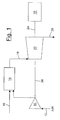
figure 1 is a schematic illustration of a gas turbine to which a method for the start-up according to the present invention can be applied; -
figure 2 is a diagram which shows the variation, in relation to the time, in the hypothetical lower heat value of a certain gaseous fuel used in the turbine offigure 1 ; -
figure 3 is a diagram which shows the variation, in relation to the time, in the hypothetical specific weight of a certain gaseous fuel used in the turbine offigure 1 ; -
figure 4 is a diagram which shows the utilization index of the turbine offigure 1 in the various application phases of the start-up method according to the present invention; -
figure 5 is a diagram which shows the heat consumption under the light off conditions in the various application phases of the start-up method of a turbine according to the present invention; and -
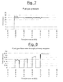
figures 6 to 10 indicate some experimental parameters, measured in relation to the time, which show the validity of the method for the start-up of a turbine according to the present invention. - With reference in particular to
figure 1 , this schematically shows a generic gas turbine, comprising acompressor 10 capable of compressing air introduced through aninlet duct 12. The compressed air is then sent to acombustor 14 to be mixed with a gaseous fuel, selected from a series of gaseous fuels having different Wobbe indexes, coming from afeeding duct 16. The combustion raises the temperature, the rate and flow volume of gas and consequently the energy contained therein. Said flow of combusted gas is directed, through aduct 18, towards aturbine 20, which transforms the energy into work energy which can be exploited for activating operating machines, such as for example, agenerator 22 connected to theturbine 20 itself by means of ashaft 24. Theturbine 20 also supplies the necessary energy for activating thecompressor 10 through therelative shaft 26, whereas the discharge gases are expelled from theturbine 20 through anoutlet duct 28. - According to the invention, the method for the start-up of a gas turbine comprises first of all a preliminary purging cycle of the
discharge duct 28, to be effected while theturbine 20 is rotating at the purging rate. As is known, "purging" refers to the periodical cleaning operation of the feeding ducts of the gaseous fuel when the relative burner line is not in use. At the end of the purging phase, the light off phase is effected, and the flow of gaseous fuel at the inlet of thecombustor 14 is set at a first predetermined minimum value FSR1, which is sufficient for igniting the richest air/fuel mixture among those which can be obtained with the different gaseous fuels, for a period of time which is adequate for filling thefeeding duct 16 and effecting a first attempt at ignition, according to the known procedures in a generic gas turbine. - At this point, if the ignition of the mixture has not taken place, an intermediate purging cycle of the
discharge duct 28 is effected, interrupting the flow of fuel to thecombustor 14. The flow of gaseous fuel entering thecombustor 14 is then set at a second predetermined value FSR2, higher than the first predetermined minimum value FSR1 and maintained for a sufficient time for effecting a further brief attempt at igniting the air/fuel mixture. In the case of ignition failure, a further purging cycle of thedischarge duct 28 will be effected. - The sequence indicated above is repeated, with successive increases in the FSRn value of the flow of gaseous fuel, until the ignition of the air/fuel mixture has been effected, or until a predetermined maximum value FSRmax of said fuel flow has been reached. If this last hypothesis is verified, i.e. if, in the meantime, it has not been possible to activate the
turbine 20, a final purging cycle must be effected, after theturbine 20 has been brought to a particularly reduced predefined rotation regime (defined in technical jargon as "crank speed"), before stopping the machine and possibly restarting with the sequence of ignition phases. - More specifically, with reference to
figures 2 to 5 , these show an illustrative ignition sequence of a turbine, using the method according to the present invention. In the diagram offigure 2 , LHV indicates the lower heat value of a certain gaseous fuel used in the turbine. The lower heat value LHV varies from a maximum value LHVmax to a minimum value LHVmin, wherein LHVmax corresponds to the lower heat value of the richest gaseous fuel among those used. The minimum value LHVmin, on the other hand, is calculated as the maximum value between the lower heat value measured by the instrumentation of the turbine, for example by means of a calorimeter, and the minimum value of the lower heat value of the poorest gaseous fuel considered safe during the start-up of the turbine. If there is no device available for measuring or estimating the heat value of the gas, the LHVcalorimeter value can be considered zero. In practice:
- In the diagram of
figure 3 , SG indicates the specific weight of a certain gaseous fuel used in the turbine. Analogously to what is specified above, the specific weight value SG varies from a maximum value SGmax to a minimum value SGmin, wherein SGmin corresponds to the specific weight of the richest gaseous fuel among those used. The maximum value SGmax, on the other hand, is calculated as the minimum value of the specific weight of the gaseous fuel considered safe during the start-up of the turbine, and is equal to:
- As in the case of the lower heat value LHV, if there is no device available for measuring or estimating the specific weight SG, the SGcalorimeter value can be considered zero.
-
Figure 5 shows the reference heat consumption under light off conditions, correlated to the utilization index MDCSW offigure 4 . In this figure, when MDCSW = 1 the ignition system is activated, whereas when MDCSW = 0 the ignition system is deactivated. - In consideration of this, the typical start-up phases of a gas turbine, in relation to the time ti and with reference to
figures 2 to 5 , can be summarized as follows: - Time to:
- the preliminary purging phase of the
discharge duct 28 is completed. The turbine is brought to the light off rotation rate. In this phase:


- the preliminary purging phase of the
- Time t1:
- the turbine is at the light off rotation rate, the ignition system is activated and the safety vents are opened. In this phase:


- the turbine is at the light off rotation rate, the ignition system is activated and the safety vents are opened. In this phase:
- Time t2:
- ignition has not taken place. An intermediate purging phase of the
discharge duct 28 is effected. The ignition system is deactivated and the safety vents are closed. In this phase:


- ignition has not taken place. An intermediate purging phase of the
- Time t3:
- the intermediate purging phase of the
discharge duct 28 is stopped. The feeding of gaseous fuel is restarted, the ignition system is activated and the safety vents are opened. In this phase:


- the intermediate purging phase of the
- Time t4:
- ignition has failed. A new intermediate purging phase of the
discharge duct 28 is effected. The ignition system is deactivated and the safety vents are closed. In this phase:


- ignition has failed. A new intermediate purging phase of the
- If, at any given time t8, the start-up of the turbine has not taken place, the light off sequence is terminated. A complete purging phase of the machine is therefore effected before its complete stoppage.
- Assuming, on the other hand, that at a certain time ti, the air/fuel mixture is ignited, the heating phase of the turbine can be started. The current lower heat values LHV and specific weight values SG of the gas are established by the control logics of the machine as values for the start-up sequence. The light off sequence is terminated and the machine is ready for heating and subsequent acceleration until the functioning rate at full regime is reached.
-
Figures 6 to 10 illustrate various experimental parameters, measured in relation to the time, obtained during a "blank" start-up test of a gas turbine in operation. Using a particularly rich gaseous fuel, it was observed that ignition was verified in the initial phases of the light off sequence whereas with a poor fuel ignition only took place in the final phases, but always fully respecting the desired safety conditions. - It can thus be seen that the method for the start-up of a gas turbine according to the present invention achieves the objectives previously specified, obtaining the following advantages:
- possibility of activating the turbine with different compositions of gaseous fuels:
- effective and safe start-up sequence;
- fewer requisites, with respect to the applications of the known type, that the compositions of gaseous fuels must have for effecting the start-up of the turbine.
- The method for the start-up of a gas turbine of the present invention thus conceived can in any case undergo numerous modifications and variants, all included in the same inventive concept. The protection scope of the invention is therefore defined by the enclosed claims.
Claims (8)
- A method for the start-up of a gas turbine of the type comprising at least one compressor (10), which compresses the air introduced therein through an inlet duct (12), at least one combustor (14), in which said compressed air is mixed and combusted with a gaseous fuel, coming from a feeding duct (16), and at least one turbine (20), which transforms the energy of the combusted gas coming from said combustor (14) into work energy, the method comprising the following phases:a) establishing a predetermined minimum value (FSR1) of the fuel flow entering said combustor (14) and effecting a first attempt at ignition; andb) progressively increasing the value (FSRn) of the fuel flow entering said combustor (14) and effecting further attempts at ignition until the complete ignition of the air/fuel mixture and consequent start-up of said turbine (20), or until a predetermined maximum value (FSRmax) of said fuel flow is reached.
- The method according to claim 1, wherein before said first phase a) a preliminary purging cycle of the discharge duct (28) of said turbine (20) is effected.
- The method according to claim 2, wherein said preliminary purging cycle is effected while said turbine (20) is rotating in particular at the purging rate or at the light off rate.
- The method according to any one of the preceding claims, wherein in said phase b) an intermediate purging cycle of said discharge duct (28) is effected, interrupting the flow of gaseous fuel to said combustor (14) before an, any or each increase in said value (FSRn) of the fuel flow.
- The method according to any one of the preceding claims, wherein after phase b), a final purging cycle of said turbine (20) is effected, in the case of ignition failure of the air/fuel mixture when said predetermined maximum value (FSRmax) of the fuel flow has been reached, to be effected after said turbine (20) has been brought to predefined rotation regime and before stopping said turbine (20) to restart with the sequence of ignition phases.
- The method according to any one of the preceding claims, also comprising purging cycles with said turbine (20) in rotation.
- The method according to any one of the preceding claims, wherein said gaseous fuel is selected from a plurality of gaseous fuels having different Wobbe indexes.
- The method according to claim 7, wherein said predetermined minimum value (FSR1) of the flow of gaseous fuel entering said combustor (14) is sufficient for igniting the richest air/fuel mixture among those obtainable with said plurality of gaseous fuels having different Wobbe indexes.
Applications Claiming Priority (1)
| Application Number | Priority Date | Filing Date | Title |
|---|---|---|---|
| IT000164A ITMI20080164A1 (en) | 2008-02-04 | 2008-02-04 | METHOD FOR STARTING A GAS TURBINE |
Publications (2)
| Publication Number | Publication Date |
|---|---|
| EP2085577A1 true EP2085577A1 (en) | 2009-08-05 |
| EP2085577B1 EP2085577B1 (en) | 2012-05-30 |
Family
ID=40291580
Family Applications (1)
| Application Number | Title | Priority Date | Filing Date |
|---|---|---|---|
| EP09151772A Active EP2085577B1 (en) | 2008-02-04 | 2009-01-30 | Method for the start-up of a gas turbine |
Country Status (8)
| Country | Link |
|---|---|
| US (1) | US8448445B2 (en) |
| EP (1) | EP2085577B1 (en) |
| JP (1) | JP5536350B2 (en) |
| KR (2) | KR20090085541A (en) |
| CN (1) | CN101503977B (en) |
| CA (1) | CA2651746C (en) |
| IT (1) | ITMI20080164A1 (en) |
| RU (1) | RU2491436C2 (en) |
Cited By (5)
| Publication number | Priority date | Publication date | Assignee | Title |
|---|---|---|---|---|
| WO2011154528A1 (en) * | 2010-06-11 | 2011-12-15 | Ge Energy Products France Snc | Method and device for starting or stopping a gas turbine engine |
| US8713946B2 (en) | 2009-11-27 | 2014-05-06 | Nuovo Pignone S.P.A. | Exhaust temperature based threshold for control method and turbine |
| US8820089B2 (en) | 2009-11-27 | 2014-09-02 | Nuovo Pignone S.P.A. | Exhaust temperature based mode control method for gas turbine and gas turbine |
| US8904803B2 (en) | 2009-11-27 | 2014-12-09 | Nuovo Pignone S.P.A. | Exhaust temperature based threshold for control method and turbine |
| US9140195B2 (en) | 2009-11-27 | 2015-09-22 | Nuovo Pignone S.P.A. | Exhaust temperature versus turbine pressure ratio based turbine control method and device |
Families Citing this family (6)
| Publication number | Priority date | Publication date | Assignee | Title |
|---|---|---|---|---|
| US8955334B2 (en) * | 2010-07-22 | 2015-02-17 | General Electric Company | Systems and methods for controlling the startup of a gas turbine |
| IT1401923B1 (en) * | 2010-09-09 | 2013-08-28 | Nuovo Pignone Spa | METHODS AND DEVICES FOR TESTING A LOW-SPEED LOW-TIME ROTOR IN A TURBOMACCHINE |
| FR2970304B1 (en) * | 2011-01-11 | 2013-02-08 | Turbomeca | METHOD FOR STARTING A TURBOMACHINE |
| EP2762687A1 (en) | 2013-02-01 | 2014-08-06 | Siemens Aktiengesellschaft | Method for starting a combustion system |
| CN104329173B (en) * | 2014-09-11 | 2016-05-25 | 中国科学院工程热物理研究所 | The control method of a kind of gas turbine fuel and air mixing ratio and device |
| CN111441869A (en) * | 2020-03-29 | 2020-07-24 | 至玥腾风科技集团有限公司 | Method and system for starting micro gas turbine |
Citations (5)
| Publication number | Priority date | Publication date | Assignee | Title |
|---|---|---|---|---|
| US6062016A (en) | 1997-04-21 | 2000-05-16 | Capstone Turbine Corporation | Gas turbine engine fixed speed light-off method |
| WO2003014551A1 (en) * | 2001-07-27 | 2003-02-20 | Elliott Energy Systems, Inc. | Method for ignition and start up of a turbogenerator |
| DE10226721A1 (en) * | 2002-06-14 | 2004-01-22 | Bbp Power Plants Gmbh I.Ins. | Control system for gas turbine generating power, has three-way valve and heat exchanger for warming fuel gas entering combustion chamber to maintain constant Wobbe number |
| US20070245745A1 (en) | 2006-04-20 | 2007-10-25 | Siemens Power Generation, Inc. | Method and device for optimizing a light-up procedure of a gas turbine engine |
| EP1860302A1 (en) * | 2006-05-22 | 2007-11-28 | Siemens Aktiengesellschaft | Gas turbine engine starting method and control device |
Family Cites Families (11)
| Publication number | Priority date | Publication date | Assignee | Title |
|---|---|---|---|---|
| SU1059236A1 (en) * | 1982-06-16 | 1983-12-07 | Производственное Объединение Турбостроения "Ленинградский Металлический Завод" | Gas-turbine plant starting system |
| JPS5915639A (en) * | 1982-07-19 | 1984-01-26 | Yanmar Diesel Engine Co Ltd | Control device of gas turbine engine |
| JPS6047167A (en) * | 1983-08-26 | 1985-03-14 | 清水建設株式会社 | Automatic conveyor in building scene of multi-storied building |
| RU2007599C1 (en) * | 1989-10-23 | 1994-02-15 | Колчин Николай Владимирович | Method of control of gas-turbine engine |
| US5274996A (en) * | 1991-10-11 | 1994-01-04 | Allied-Signal, Inc. | Closed loop fuel control system |
| JP2961018B2 (en) * | 1992-07-06 | 1999-10-12 | 三菱重工業株式会社 | Gas turbine engine arrival / misfire monitoring method |
| JPH07253030A (en) * | 1994-03-15 | 1995-10-03 | Mitsubishi Heavy Ind Ltd | Gas turbine restarting method |
| DE4412315B4 (en) | 1994-04-11 | 2005-12-15 | Alstom | Method and device for operating the combustion chamber of a gas turbine |
| US5966925A (en) | 1996-04-26 | 1999-10-19 | Kabushiki Kaisha Toshiba | Gas turbine power plant control for starting and stopping |
| US7565805B2 (en) * | 2005-11-22 | 2009-07-28 | General Electric Company | Method for operating gas turbine engine systems |
| CN100389252C (en) | 2006-05-31 | 2008-05-21 | 东北大学 | Start control device and method for micro gas turbine high speed engine |
-
2008
- 2008-02-04 IT IT000164A patent/ITMI20080164A1/en unknown
-
2009
- 2009-01-30 CA CA2651746A patent/CA2651746C/en active Active
- 2009-01-30 EP EP09151772A patent/EP2085577B1/en active Active
- 2009-02-02 JP JP2009021343A patent/JP5536350B2/en active Active
- 2009-02-03 KR KR1020090008550A patent/KR20090085541A/en active Application Filing
- 2009-02-03 US US12/364,580 patent/US8448445B2/en active Active
- 2009-02-03 RU RU2009103539/06A patent/RU2491436C2/en active
- 2009-02-04 CN CN200910005788.4A patent/CN101503977B/en not_active Expired - Fee Related
-
2015
- 2015-08-20 KR KR1020150117222A patent/KR20150110439A/en not_active Application Discontinuation
Patent Citations (5)
| Publication number | Priority date | Publication date | Assignee | Title |
|---|---|---|---|---|
| US6062016A (en) | 1997-04-21 | 2000-05-16 | Capstone Turbine Corporation | Gas turbine engine fixed speed light-off method |
| WO2003014551A1 (en) * | 2001-07-27 | 2003-02-20 | Elliott Energy Systems, Inc. | Method for ignition and start up of a turbogenerator |
| DE10226721A1 (en) * | 2002-06-14 | 2004-01-22 | Bbp Power Plants Gmbh I.Ins. | Control system for gas turbine generating power, has three-way valve and heat exchanger for warming fuel gas entering combustion chamber to maintain constant Wobbe number |
| US20070245745A1 (en) | 2006-04-20 | 2007-10-25 | Siemens Power Generation, Inc. | Method and device for optimizing a light-up procedure of a gas turbine engine |
| EP1860302A1 (en) * | 2006-05-22 | 2007-11-28 | Siemens Aktiengesellschaft | Gas turbine engine starting method and control device |
Cited By (6)
| Publication number | Priority date | Publication date | Assignee | Title |
|---|---|---|---|---|
| US8713946B2 (en) | 2009-11-27 | 2014-05-06 | Nuovo Pignone S.P.A. | Exhaust temperature based threshold for control method and turbine |
| US8820089B2 (en) | 2009-11-27 | 2014-09-02 | Nuovo Pignone S.P.A. | Exhaust temperature based mode control method for gas turbine and gas turbine |
| US8904803B2 (en) | 2009-11-27 | 2014-12-09 | Nuovo Pignone S.P.A. | Exhaust temperature based threshold for control method and turbine |
| US9140195B2 (en) | 2009-11-27 | 2015-09-22 | Nuovo Pignone S.P.A. | Exhaust temperature versus turbine pressure ratio based turbine control method and device |
| WO2011154528A1 (en) * | 2010-06-11 | 2011-12-15 | Ge Energy Products France Snc | Method and device for starting or stopping a gas turbine engine |
| FR2961261A1 (en) * | 2010-06-11 | 2011-12-16 | Ge Energy Products France Snc | METHOD AND DEVICE FOR STARTING OR STOPPING A GAS TURBINE |
Also Published As
| Publication number | Publication date |
|---|---|
| KR20090085541A (en) | 2009-08-07 |
| CN101503977B (en) | 2015-02-25 |
| CA2651746C (en) | 2016-05-10 |
| US20100126179A1 (en) | 2010-05-27 |
| JP2009185817A (en) | 2009-08-20 |
| CA2651746A1 (en) | 2009-08-04 |
| ITMI20080164A1 (en) | 2009-08-05 |
| RU2009103539A (en) | 2010-08-10 |
| JP5536350B2 (en) | 2014-07-02 |
| RU2491436C2 (en) | 2013-08-27 |
| KR20150110439A (en) | 2015-10-02 |
| CN101503977A (en) | 2009-08-12 |
| US8448445B2 (en) | 2013-05-28 |
| EP2085577B1 (en) | 2012-05-30 |
Similar Documents
| Publication | Publication Date | Title |
|---|---|---|
| EP2085577B1 (en) | Method for the start-up of a gas turbine | |
| RU2482393C2 (en) | Method and device to control combustion in gas turbine | |
| US7861534B2 (en) | Method of starting turbine engine from low engine speed | |
| JP4118811B2 (en) | Gas turbine engine starting method | |
| JP6633960B2 (en) | Ignition detection device for aircraft gas turbine engine | |
| EP3650676A1 (en) | Fuel flow control system and method for engine start | |
| JP2007315398A (en) | Method for gas turbine operation during under-frequency operation through use of air extraction | |
| US20040122581A1 (en) | Multiple control loop acceleration of turboalternator after reaching self-sustaining speed previous to reaching synchronous speed | |
| EP2644865A2 (en) | Method of startup control for a gas turbine system operating in a fired deceleration shutdown process mode | |
| RU2594843C2 (en) | Method for gas turbine engine start-up | |
| JP6633962B2 (en) | Aircraft gas turbine engine controller | |
| US8844295B2 (en) | Method for meeting a purge flow requirement for a power plant and a power plant having a purge control system | |
| US9464574B2 (en) | Method for running up a stationary gas turbine | |
| US20130104561A1 (en) | Active fuel control on gas turbine shutdown sequence | |
| JP5222008B2 (en) | Method and apparatus for restarting single-shaft combined plant | |
| JP5931556B2 (en) | Gas turbine control device, gas turbine, and gas turbine control method | |
| JP2003201864A (en) | Starting method of gas turbine device and gas turbine device |
Legal Events
| Date | Code | Title | Description |
|---|---|---|---|
| PUAI | Public reference made under article 153(3) epc to a published international application that has entered the european phase |
Free format text: ORIGINAL CODE: 0009012 |
|
| AK | Designated contracting states |
Kind code of ref document: A1 Designated state(s): AT BE BG CH CY CZ DE DK EE ES FI FR GB GR HR HU IE IS IT LI LT LU LV MC MK MT NL NO PL PT RO SE SI SK TR |
|
| AX | Request for extension of the european patent |
Extension state: AL BA RS |
|
| 17P | Request for examination filed |
Effective date: 20100205 |
|
| 17Q | First examination report despatched |
Effective date: 20100310 |
|
| AKX | Designation fees paid |
Designated state(s): AT BE BG CH CY CZ DE DK EE ES FI FR GB GR HR HU IE IS IT LI LT LU LV MC MK MT NL NO PL PT RO SE SI SK TR |
|
| GRAP | Despatch of communication of intention to grant a patent |
Free format text: ORIGINAL CODE: EPIDOSNIGR1 |
|
| GRAS | Grant fee paid |
Free format text: ORIGINAL CODE: EPIDOSNIGR3 |
|
| GRAA | (expected) grant |
Free format text: ORIGINAL CODE: 0009210 |
|
| AK | Designated contracting states |
Kind code of ref document: B1 Designated state(s): AT BE BG CH CY CZ DE DK EE ES FI FR GB GR HR HU IE IS IT LI LT LU LV MC MK MT NL NO PL PT RO SE SI SK TR |
|
| REG | Reference to a national code |
Ref country code: GB Ref legal event code: FG4D |
|
| REG | Reference to a national code |
Ref country code: CH Ref legal event code: EP |
|
| REG | Reference to a national code |
Ref country code: AT Ref legal event code: REF Ref document number: 560180 Country of ref document: AT Kind code of ref document: T Effective date: 20120615 |
|
| REG | Reference to a national code |
Ref country code: IE Ref legal event code: FG4D |
|
| REG | Reference to a national code |
Ref country code: CH Ref legal event code: NV Representative=s name: SERVOPATENT GMBH |
|
| REG | Reference to a national code |
Ref country code: DE Ref legal event code: R096 Ref document number: 602009007267 Country of ref document: DE Effective date: 20120726 |
|
| REG | Reference to a national code |
Ref country code: NL Ref legal event code: T3 |
|
| REG | Reference to a national code |
Ref country code: NO Ref legal event code: T2 Effective date: 20120530 |
|
| REG | Reference to a national code |
Ref country code: LT Ref legal event code: MG4D Effective date: 20120530 |
|
| PG25 | Lapsed in a contracting state [announced via postgrant information from national office to epo] |
Ref country code: CY Free format text: LAPSE BECAUSE OF FAILURE TO SUBMIT A TRANSLATION OF THE DESCRIPTION OR TO PAY THE FEE WITHIN THE PRESCRIBED TIME-LIMIT Effective date: 20120530 Ref country code: LT Free format text: LAPSE BECAUSE OF FAILURE TO SUBMIT A TRANSLATION OF THE DESCRIPTION OR TO PAY THE FEE WITHIN THE PRESCRIBED TIME-LIMIT Effective date: 20120530 Ref country code: SE Free format text: LAPSE BECAUSE OF FAILURE TO SUBMIT A TRANSLATION OF THE DESCRIPTION OR TO PAY THE FEE WITHIN THE PRESCRIBED TIME-LIMIT Effective date: 20120530 Ref country code: IS Free format text: LAPSE BECAUSE OF FAILURE TO SUBMIT A TRANSLATION OF THE DESCRIPTION OR TO PAY THE FEE WITHIN THE PRESCRIBED TIME-LIMIT Effective date: 20120930 Ref country code: FI Free format text: LAPSE BECAUSE OF FAILURE TO SUBMIT A TRANSLATION OF THE DESCRIPTION OR TO PAY THE FEE WITHIN THE PRESCRIBED TIME-LIMIT Effective date: 20120530 |
|
| REG | Reference to a national code |
Ref country code: AT Ref legal event code: MK05 Ref document number: 560180 Country of ref document: AT Kind code of ref document: T Effective date: 20120530 |
|
| PG25 | Lapsed in a contracting state [announced via postgrant information from national office to epo] |
Ref country code: LV Free format text: LAPSE BECAUSE OF FAILURE TO SUBMIT A TRANSLATION OF THE DESCRIPTION OR TO PAY THE FEE WITHIN THE PRESCRIBED TIME-LIMIT Effective date: 20120530 Ref country code: GR Free format text: LAPSE BECAUSE OF FAILURE TO SUBMIT A TRANSLATION OF THE DESCRIPTION OR TO PAY THE FEE WITHIN THE PRESCRIBED TIME-LIMIT Effective date: 20120831 Ref country code: SI Free format text: LAPSE BECAUSE OF FAILURE TO SUBMIT A TRANSLATION OF THE DESCRIPTION OR TO PAY THE FEE WITHIN THE PRESCRIBED TIME-LIMIT Effective date: 20120530 Ref country code: HR Free format text: LAPSE BECAUSE OF FAILURE TO SUBMIT A TRANSLATION OF THE DESCRIPTION OR TO PAY THE FEE WITHIN THE PRESCRIBED TIME-LIMIT Effective date: 20120530 |
|
| PG25 | Lapsed in a contracting state [announced via postgrant information from national office to epo] |
Ref country code: BE Free format text: LAPSE BECAUSE OF FAILURE TO SUBMIT A TRANSLATION OF THE DESCRIPTION OR TO PAY THE FEE WITHIN THE PRESCRIBED TIME-LIMIT Effective date: 20120530 |
|
| PG25 | Lapsed in a contracting state [announced via postgrant information from national office to epo] |
Ref country code: AT Free format text: LAPSE BECAUSE OF FAILURE TO SUBMIT A TRANSLATION OF THE DESCRIPTION OR TO PAY THE FEE WITHIN THE PRESCRIBED TIME-LIMIT Effective date: 20120530 Ref country code: SK Free format text: LAPSE BECAUSE OF FAILURE TO SUBMIT A TRANSLATION OF THE DESCRIPTION OR TO PAY THE FEE WITHIN THE PRESCRIBED TIME-LIMIT Effective date: 20120530 Ref country code: CZ Free format text: LAPSE BECAUSE OF FAILURE TO SUBMIT A TRANSLATION OF THE DESCRIPTION OR TO PAY THE FEE WITHIN THE PRESCRIBED TIME-LIMIT Effective date: 20120530 Ref country code: RO Free format text: LAPSE BECAUSE OF FAILURE TO SUBMIT A TRANSLATION OF THE DESCRIPTION OR TO PAY THE FEE WITHIN THE PRESCRIBED TIME-LIMIT Effective date: 20120530 Ref country code: DK Free format text: LAPSE BECAUSE OF FAILURE TO SUBMIT A TRANSLATION OF THE DESCRIPTION OR TO PAY THE FEE WITHIN THE PRESCRIBED TIME-LIMIT Effective date: 20120530 Ref country code: EE Free format text: LAPSE BECAUSE OF FAILURE TO SUBMIT A TRANSLATION OF THE DESCRIPTION OR TO PAY THE FEE WITHIN THE PRESCRIBED TIME-LIMIT Effective date: 20120530 |
|
| PG25 | Lapsed in a contracting state [announced via postgrant information from national office to epo] |
Ref country code: PL Free format text: LAPSE BECAUSE OF FAILURE TO SUBMIT A TRANSLATION OF THE DESCRIPTION OR TO PAY THE FEE WITHIN THE PRESCRIBED TIME-LIMIT Effective date: 20120530 Ref country code: PT Free format text: LAPSE BECAUSE OF FAILURE TO SUBMIT A TRANSLATION OF THE DESCRIPTION OR TO PAY THE FEE WITHIN THE PRESCRIBED TIME-LIMIT Effective date: 20121001 |
|
| PLBE | No opposition filed within time limit |
Free format text: ORIGINAL CODE: 0009261 |
|
| STAA | Information on the status of an ep patent application or granted ep patent |
Free format text: STATUS: NO OPPOSITION FILED WITHIN TIME LIMIT |
|
| PG25 | Lapsed in a contracting state [announced via postgrant information from national office to epo] |
Ref country code: ES Free format text: LAPSE BECAUSE OF FAILURE TO SUBMIT A TRANSLATION OF THE DESCRIPTION OR TO PAY THE FEE WITHIN THE PRESCRIBED TIME-LIMIT Effective date: 20120910 |
|
| 26N | No opposition filed |
Effective date: 20130301 |
|
| REG | Reference to a national code |
Ref country code: DE Ref legal event code: R097 Ref document number: 602009007267 Country of ref document: DE Effective date: 20130301 |
|
| PG25 | Lapsed in a contracting state [announced via postgrant information from national office to epo] |
Ref country code: BG Free format text: LAPSE BECAUSE OF FAILURE TO SUBMIT A TRANSLATION OF THE DESCRIPTION OR TO PAY THE FEE WITHIN THE PRESCRIBED TIME-LIMIT Effective date: 20120830 |
|
| PG25 | Lapsed in a contracting state [announced via postgrant information from national office to epo] |
Ref country code: MC Free format text: LAPSE BECAUSE OF NON-PAYMENT OF DUE FEES Effective date: 20130131 |
|
| REG | Reference to a national code |
Ref country code: IE Ref legal event code: MM4A |
|
| PG25 | Lapsed in a contracting state [announced via postgrant information from national office to epo] |
Ref country code: IE Free format text: LAPSE BECAUSE OF NON-PAYMENT OF DUE FEES Effective date: 20130130 |
|
| PG25 | Lapsed in a contracting state [announced via postgrant information from national office to epo] |
Ref country code: MT Free format text: LAPSE BECAUSE OF FAILURE TO SUBMIT A TRANSLATION OF THE DESCRIPTION OR TO PAY THE FEE WITHIN THE PRESCRIBED TIME-LIMIT Effective date: 20120530 |
|
| PG25 | Lapsed in a contracting state [announced via postgrant information from national office to epo] |
Ref country code: TR Free format text: LAPSE BECAUSE OF FAILURE TO SUBMIT A TRANSLATION OF THE DESCRIPTION OR TO PAY THE FEE WITHIN THE PRESCRIBED TIME-LIMIT Effective date: 20120530 |
|
| PG25 | Lapsed in a contracting state [announced via postgrant information from national office to epo] |
Ref country code: LU Free format text: LAPSE BECAUSE OF NON-PAYMENT OF DUE FEES Effective date: 20130130 Ref country code: MK Free format text: LAPSE BECAUSE OF FAILURE TO SUBMIT A TRANSLATION OF THE DESCRIPTION OR TO PAY THE FEE WITHIN THE PRESCRIBED TIME-LIMIT Effective date: 20120530 Ref country code: HU Free format text: LAPSE BECAUSE OF FAILURE TO SUBMIT A TRANSLATION OF THE DESCRIPTION OR TO PAY THE FEE WITHIN THE PRESCRIBED TIME-LIMIT; INVALID AB INITIO Effective date: 20090130 |
|
| REG | Reference to a national code |
Ref country code: FR Ref legal event code: PLFP Year of fee payment: 8 |
|
| PGFP | Annual fee paid to national office [announced via postgrant information from national office to epo] |
Ref country code: NL Payment date: 20160126 Year of fee payment: 8 |
|
| PGFP | Annual fee paid to national office [announced via postgrant information from national office to epo] |
Ref country code: NO Payment date: 20160127 Year of fee payment: 8 Ref country code: CH Payment date: 20160127 Year of fee payment: 8 |
|
| REG | Reference to a national code |
Ref country code: FR Ref legal event code: PLFP Year of fee payment: 9 |
|
| REG | Reference to a national code |
Ref country code: NO Ref legal event code: MMEP |
|
| REG | Reference to a national code |
Ref country code: CH Ref legal event code: PL |
|
| REG | Reference to a national code |
Ref country code: NL Ref legal event code: MM Effective date: 20170201 |
|
| PG25 | Lapsed in a contracting state [announced via postgrant information from national office to epo] |
Ref country code: LI Free format text: LAPSE BECAUSE OF NON-PAYMENT OF DUE FEES Effective date: 20170131 Ref country code: NO Free format text: LAPSE BECAUSE OF NON-PAYMENT OF DUE FEES Effective date: 20170131 Ref country code: CH Free format text: LAPSE BECAUSE OF NON-PAYMENT OF DUE FEES Effective date: 20170131 |
|
| PG25 | Lapsed in a contracting state [announced via postgrant information from national office to epo] |
Ref country code: NL Free format text: LAPSE BECAUSE OF NON-PAYMENT OF DUE FEES Effective date: 20170201 |
|
| REG | Reference to a national code |
Ref country code: FR Ref legal event code: PLFP Year of fee payment: 10 |
|
| REG | Reference to a national code |
Ref country code: GB Ref legal event code: 732E Free format text: REGISTERED BETWEEN 20220728 AND 20220803 |
|
| PGFP | Annual fee paid to national office [announced via postgrant information from national office to epo] |
Ref country code: IT Payment date: 20230103 Year of fee payment: 15 Ref country code: DE Payment date: 20221220 Year of fee payment: 15 |
|
| PGFP | Annual fee paid to national office [announced via postgrant information from national office to epo] |
Ref country code: GB Payment date: 20231219 Year of fee payment: 16 |
|
| PGFP | Annual fee paid to national office [announced via postgrant information from national office to epo] |
Ref country code: FR Payment date: 20231219 Year of fee payment: 16 |