EP2085562A2 - Mosquito-net with rollaway net-guiding chain for net with horizontal sliding - Google Patents
Mosquito-net with rollaway net-guiding chain for net with horizontal sliding Download PDFInfo
- Publication number
- EP2085562A2 EP2085562A2 EP09001215A EP09001215A EP2085562A2 EP 2085562 A2 EP2085562 A2 EP 2085562A2 EP 09001215 A EP09001215 A EP 09001215A EP 09001215 A EP09001215 A EP 09001215A EP 2085562 A2 EP2085562 A2 EP 2085562A2
- Authority
- EP
- European Patent Office
- Prior art keywords
- net
- guiding chain
- handlebar
- mosquito
- chain
- Prior art date
- Legal status (The legal status is an assumption and is not a legal conclusion. Google has not performed a legal analysis and makes no representation as to the accuracy of the status listed.)
- Withdrawn
Links
- 230000005540 biological transmission Effects 0.000 claims abstract description 3
- 230000010355 oscillation Effects 0.000 description 3
- 241000238631 Hexapoda Species 0.000 description 2
- 238000009434 installation Methods 0.000 description 2
- 230000000007 visual effect Effects 0.000 description 2
- 206010043268 Tension Diseases 0.000 description 1
- XAGFODPZIPBFFR-UHFFFAOYSA-N aluminium Chemical compound [Al] XAGFODPZIPBFFR-UHFFFAOYSA-N 0.000 description 1
- 229910052782 aluminium Inorganic materials 0.000 description 1
- 239000004411 aluminium Substances 0.000 description 1
- 230000000694 effects Effects 0.000 description 1
- 230000007246 mechanism Effects 0.000 description 1
- 230000002085 persistent effect Effects 0.000 description 1
- 230000001681 protective effect Effects 0.000 description 1
- 230000000306 recurrent effect Effects 0.000 description 1
- 238000005096 rolling process Methods 0.000 description 1
- 238000004804 winding Methods 0.000 description 1
Images


Classifications
-
- E—FIXED CONSTRUCTIONS
- E06—DOORS, WINDOWS, SHUTTERS, OR ROLLER BLINDS IN GENERAL; LADDERS
- E06B—FIXED OR MOVABLE CLOSURES FOR OPENINGS IN BUILDINGS, VEHICLES, FENCES OR LIKE ENCLOSURES IN GENERAL, e.g. DOORS, WINDOWS, BLINDS, GATES
- E06B9/00—Screening or protective devices for wall or similar openings, with or without operating or securing mechanisms; Closures of similar construction
- E06B9/52—Devices affording protection against insects, e.g. fly screens; Mesh windows for other purposes
- E06B9/54—Roller fly screens
- E06B2009/543—Horizontally moving screens
Definitions
- the subject of this invention is a mosquito-net with rollaway net-guiding chain for net with horizontal sliding.
- the invention finds particular even if not exclusive application in the field of mosquito-nets suitable for preventing insects from entering conventionally inhabited places, for example houses and offices.
- the mosquito-nets can be put into two categories.
- a second, indicated as mosquito-net in assembly kits, is that much more common on the market.
- the roller shutter box In both said categories of mosquito-nets, there are common realization elements; which can be explicited by the roller shutter box, of the type generally given by a profile or extruded aluminium bar, on the inside of which is coaxially inserted the mosquito-net roller.
- the roller In the non-motorized version, the roller may also include one corresponding preloaded return spring.
- Concerning the ends of the roller shutter box they are normally closed by suitable plates, or better heads, which are supplied in two versions, fixed or with counter-plates or caps which are adjustable.
- the roller shutter box combines in the installation with one or more guides or slide-ways, inside of which the end of the handlebar and the corresponding side edge of the net slides in and out.
- a shielding device for a horizontally sliding screen comprising a foldable shield that is pleated, having a base side, a left-hand side and a right-hand side, the shield extending longitudinally between a left-hand frame element extending upwards and a right-hand frame element extending upwards, longitudinally movable the one with respect to the other in order to open the foldable shield, the apparatus including moreover a top guide element extending longitudinally and an base guide element extending longitudinally, each guide element being flexible and bent in a cross direction adjacently to one of the left-hand and right-hand frame elements so as to present a free end that moves downwards and upwards as regards one of said left-hand and right-hand frame elements when the shield is opened or closed, each guide element having flexing elasticity determining an elastic return force, characterised in that the free ends of each guide element slides along one of said left-hand or right-hand frame elements, in that the other end of each guide element is fixed to the other one of
- EP 999335 (Metaco) describes a shielding device including:
- a flexible guide structure made up of a number of rigid units pivotably connected one after another by means of pins.
- the guide structure engaged in a slidable way along a fixed section, presents an end fixed on the movable stanchion and an end section sliding and guided along a shaped prolongation of the section.
- the guide structure therefore maintains a rectilinear development in the section extracted from the fixed stanchion, and flexes at the input opening in the stanchion to be housed and extracted from the same in accordance with the opening and closing movements of the curtain.
- the represented screen solutions all aim to contain, if not apparently eliminate, the visual impact of horizontal and parallel guides that are usually placed along the horizontal levels that delimit, on the upper and lower part the architectonic opening to be closed with said protective screen.
- the represented solutions are not able to minimize the sizes of guides where present, with an aesthetic aspect that results in conclusion little acceptable.
- the mechanisms are not particularly efficient in allowing for manageable, that is smooth, screen movement, without stick-slip-motions, thus not guaranteeing linear sliding and the correct tension of the net.
- the illustrated solutions seem constructively complex, not easily manufacturable also due to the presence of a large number of codes that complicate warehouse management.
- the aim of this invention is also to avoid the above-mentioned drawbacks.
- a first and unquestionable value as regards the conventional mosquito-nets, consists in the fact that the mosquito-net does not have a lower guide, and in any case, for particularly wide openings, can provide also a thin and rectilinear line but that however has an extremely contained thickness (less than 3mm with a tolerance of ⁇ 0.2mm). Moreover, said thin line has no guide function for facilitating the rectilinear sliding of the handlebar, but is only a means for containing the side oscillation of the net-guiding chain.
- the prevision of the roller, inside the roller shutter box allows for a persistent yet light tension on the net, which, when pulled out offers greater guarantee of effectiveness against intruding insects, and simultaneously the tenseness remains uniform and particularly resisting to the deformations also with insistent pressure on the surface of same, e.g. because of a faster air circulation or usual gusts of wind.
- the movement of the handlebar is smooth and easy, whether the net is pulled out or wound up, requiring only slight effort from the user.
- One more aim is that the assembly and vice-versa of the mosquito-net is more effective and noticeably comfortable, the roller shutter box is contained dimensionally, favouring housing in the narrow seats and as a whole with less visual impact.
- the mosquito-net 1a, 1 b includes at least: a side and vertical roller shutter box 10 that contains a roller 100 of the net or screen 200, a ; handlebar 20, a fixed upper guide 30 and a lower net-guiding chain 40.
- the roller 100 ( figs. 3 , 4 ) is longitudinally housed, with the related net or screen 200.
- the net or screen 200 is with a first end joined to said roller 100 around which it is wound, then turned exiting sideways from the roller shutter box 10 by means of the coming and going movement, along the horizontal axis of the handlebar 20 to which said net 200 is vertically joined with the second end.
- the upper end 21 of the handlebar 20 is driven by the upper guide 30, horizontal, that is fixed at the lintel of the architectonic opening, while the lower end 22 is configured so as to lay down, with the participation of the driving device, the net-guiding chain 40 that also slides inside and along the handlebar 20.
- the function of the net-guiding chain 40 is particularly to hold and drive during its distending, after the movement of the handlebar 20, the lower border 201 of the net 200, while the top edge 202 of the net 200 slides and remains inside the upper guide 30.
- the roller 100 that is vertically contained inside the roller shutter box 10, comprises ( figures 3 , 4 and 5 ) of a cylindrical pipe, on the surface of which it clamps the first end of the net 200. Inside the pipe there is a spiral spring 102, coaxial to a sleeve 103, this spiral spring 102 on one side is joined to a key 104 that is attached along the inside wall of the cylindrical pipe, on the other exiting from the sleeve 103, engaging a shaft 105, with a gear-wheel 106 keyed on the top.
- the roller 100 is thus introduced inside the roller shutter box 10 and is held in vertical position by means of the base 11 and head 12 ( figure 3 ) that close the two ends, respectively lower and upper, of the roller shutter box 10.
- the base 11 besides closing the lower end of the roller shutter box 10, allowing pivoting by means of the pin 110 of the roller 100 closed by the head 107, is provided with two side appendixes 111 ( figure 3 and 4 ) to the which the first end 400 of the net-guiding chain 40 ( figure 5 ) is engaged .
- the head 12 ( figure 3 and 4 ) that is applied on the upper part of the roller shutter box 10 is shaped with a recess 120 inside of which the gear-wheel 106 is housed that is connected with the spiral spring 102.
- the driving device ( figure 5 ) of the net-guiding chain 40 includes the gear-wheel 106, which engages the chain 50 made up at least for a part by a number of balls one after another with the first end 51 that is engaged at the upper end 21 of the handlebar 20.
- the chain 50 that originates from the handlebar 20 runs along and inside the upper guide 30, carries out a geared first turn around the gear-wheel 106, and then by means of a pulley 60 hinged in the upper end 21 of the handlebar 20 is transmitted towards the lower end 22 of the handlebar 20.
- the pulley 61 is hinged around which the rope portion of the chain 50 rotates to be forced upwards to turn around the pulley 62 that is hinged to the head module 41 of the net-guiding chain 40, then again transmitted downwards in such a way that the second end 52 fixes at the lower end 22 of the handlebar 20.
- the net-guiding chain 40 consists of a series of modules 41, one hinged to another, in such a way as to result reciprocally concatenated, and slides longitudinally guided inside the handlebar 20 that is hollow.
- a rope 70 is placed along the fixed upper guide 30 with a first end 71 engaged at the end 301 of the fixed upper guide 30 and with the second end 72 transmitted by means of the pulley 63 hinged on the top 21 of the handlebar 20 downwards, to be engaged to the head module 41 of the net-guiding chain 40.
- the handlebar 20 at the lower end 22 is shaped to provide a curved guide 220 accessible through the removal of a cover 221 along which the net-guiding chain 40 is transmitted to scroll along the handlebar 20.
- the mosquito-net 1a is shown only with the lower net-guiding chain 40 that is de-placed on the lower plane of the architectonic opening, holding only the lower edge 201 of the net 200, each module 41 on the upper part being configured in such a way as to provide a continuous seat 410 inside of which said lower edge 201 of the net 200 is longitudinally housed.
- the mosquito-net 1 b suitable for a mosquito-net of particular width provides the combination of a thin rectilinear line 80, applied along the plane of the architectonic opening, along which lays the net-guiding chain 40, whose thickness is less than 3mm, in this case with a tolerance of ⁇ 0.2mm.
- the function of the net-guiding chain 40 is also to prevent the possible side oscillation of said net 200 and of the net-guiding chain 40, each module 41 being provided with a lower corresponding seat, in such a way as to obtain a continuous seat 411, that develops for the whole length of the net-guiding chain 40.
- the seat 411 then substantially straddles the thin line 80 with the parallel walls 412, at the longitudinal edges of the thin line 80. In this way the alignment of the net-guiding chain 40 is also assured, simplified by the possible presence of a sliding guide placed at the lower end 22 of the handlebar 20.
Landscapes
- Engineering & Computer Science (AREA)
- Structural Engineering (AREA)
- Life Sciences & Earth Sciences (AREA)
- Insects & Arthropods (AREA)
- Pest Control & Pesticides (AREA)
- Architecture (AREA)
- Civil Engineering (AREA)
- Catching Or Destruction (AREA)
- Operating, Guiding And Securing Of Roll- Type Closing Members (AREA)
Abstract
a) a vertical roller shutter box (10) containing a roller (100), lateral compared to a horizontal and fixed upper guide (30), said net joined with a first end to the roller (100);
b) a horizontal and fixed upper guide (30);
c) a vertical handlebar (20) to which the second end of the net is joined, with the upper end fixed to the fixed guide and mobile longitudinally;
d) a net-guiding chain (40) with containing seat of the lower border (201) of the net; consisting of modular elements (41) reciprocally interconnected, with a engaged first end (400) at the lower end of the roller shutter box (100), while the second end slides inside the handlebar bar (20);
e) a driving device of the net-guiding chain (40), comprising at least a rope (70), chain (50), and relative transmission means placed at least at the handlebar (20) and the roller shutter box (10).
Description
- The subject of this invention is a mosquito-net with rollaway net-guiding chain for net with horizontal sliding.
- The invention, finds particular even if not exclusive application in the field of mosquito-nets suitable for preventing insects from entering conventionally inhabited places, for example houses and offices.
- The mosquito-nets can be put into two categories. A first, so-called made-to-measure, that is a type of mosquito-net realised according to sizes received from the client, to be delivered to the final recipient allowing for the installation by specialist staff; a second, indicated as mosquito-net in assembly kits, is that much more common on the market.
- In both said categories of mosquito-nets, there are common realization elements; which can be explicited by the roller shutter box, of the type generally given by a profile or extruded aluminium bar, on the inside of which is coaxially inserted the mosquito-net roller. In the non-motorized version, the roller may also include one corresponding preloaded return spring. Concerning the ends of the roller shutter box, they are normally closed by suitable plates, or better heads, which are supplied in two versions, fixed or with counter-plates or caps which are adjustable. The roller shutter box combines in the installation with one or more guides or slide-ways, inside of which the end of the handlebar and the corresponding side edge of the net slides in and out.
- There are also known variations, which however are very similar to the described solutions and are recurrent, as much in the mosquito-nets, as in rolling curtains and, finally, in the shade curtains. One of these, for example, regards less valuable mosquito-nets, without the preloaded spring inside. These are differentiated from the first ones, because they require manual operations, both for unwinding the curtain from the roll and for rewinding it. In one case, for example, a closed circuit chain is used, which engaging, from one side, a wheel or pulley keyed to the relative roller, housed in a roller shutter box, determines the winding, or unwinding of the mosquito-net in a controlled way.
- These mosquito-net solutions, which slide the net horizontally or vertically, are therefore composed as such:
- a) a roller shutter box, closed at the ends by corresponding heads;
- b) a roller, inside said roller shutter box, supported at the ends by a couple of heads, which are engaged at the end of the roller shutter box;
- c) a possible helicoidal torsion spring placed coaxially, cooperating with said roller;
- d) a net, anchored on one side to said roller and at the other joined to a handlebar;
- e) and finally, in the solution with vertically sliding net, two parallel slide-ways, inside of which are slideable ends of said handlebar and the side flaps of the net. For the horizontally sliding net, the slide-ways act as guides, and usually are placed, respectively, a first one along the lintel of the opening to be closed and a second one along the lower plane.
- In
EP753642 -
EP 999335 - a couple of assembly frames of the shield respectively opposite, at least one of which is sliding;
- a shield mounted between said assembly frames of the shield in order to allow for its opening and closing;
- a sliding guide frame situated close to a side of said shield not connected to the shield assembly frame, at least one end of which is an insertable free end and is extractable from inside of one of said shield assembly frames.
- Guides made up with rigid units consecutively interconnected are known. In
JP 53-51648 JP 06-158961
In conclusion, it is also reasonable to consider known: - a) a shielding body that includes a base, two sides and a top;
- b) two longitudinally movable vertical stanchions;
- c) an upper guide element and a lower guide element which are flexible and folded along one of the stanchions with a free end that moves downwards and upwards;
- d) the end opposite to the free one of the upper and lower guide elements is engaged along the stanchion;
- e) the stanchions and the upper and lower guide elements form a frame.
- a) a couple of stanchions, shield or screen assembly frame, at least one sliding;
- b) a screen;
- c) a sliding guide element, not connected to the couple of stanchions, with an end free to slide in one of said stanchions;
- d) the sliding guide element is formed by adjacent rigid interconnected units, each with a couple of parallel side-walls and a connecting portion that joins the walls, and in which the rigid units turn so that the guide element is foldable;
- e) stopping means that preserve the straightness of the guide element portion when it is extracted from the stanchion.
- From the functional point of view, the represented screen solutions all aim to contain, if not apparently eliminate, the visual impact of horizontal and parallel guides that are usually placed along the horizontal levels that delimit, on the upper and lower part the architectonic opening to be closed with said protective screen. However, the represented solutions are not able to minimize the sizes of guides where present, with an aesthetic aspect that results in conclusion little acceptable. Furthermore, as regards the solutions both with guides and without guides, the mechanisms are not particularly efficient in allowing for manageable, that is smooth, screen movement, without stick-slip-motions, thus not guaranteeing linear sliding and the correct tension of the net. In addition, the illustrated solutions seem constructively complex, not easily manufacturable also due to the presence of a large number of codes that complicate warehouse management.
- From these introductive considerations, identifying alternative solutions is certainly preeminent.
- The aim of this invention is also to avoid the above-mentioned drawbacks.
- This and other aims are reached by the present invention according to the characteristics as in the included claims solving the arising problems by means of a mosquito-net with rollaway net-guiding chain for net with horizontal sliding, made up of:
- a) a vertical roller shutter box, lateral as regards a horizontal and fixed upper guide, containing the net roller; said net is joined with a first end to the roller;
- b) a horizontal and fixed upper guide, joined with an end at the upper end of the vertical roller shutter box;
- c) a vertical handlebar to which the second end of the net is joined; the handlebar being with the upper end constrained to the fixed guide and mobile longitudinally as to said fixed guide;
- d) a net-guiding chain with seat containing the lower edge of the net; the net-guiding chain consisting of modular elements which are interconnected, where said net-guiding chain is with a first end engaged to the lower end of the roller shutter box, while the second end slides inside the handlebar;
- e) a driving device of the net-guiding chain, comprised at least of a rope, chain, and relative transmission means placed at least inside the handlebar and the roller shutter box.
- In this way, by the considerable creative contribution the effect of which constitutes immediate technical progress, multiple advantages are achieved.
- A first and unquestionable value, as regards the conventional mosquito-nets, consists in the fact that the mosquito-net does not have a lower guide, and in any case, for particularly wide openings, can provide also a thin and rectilinear line but that however has an extremely contained thickness (less than 3mm with a tolerance of ±0.2mm). Moreover, said thin line has no guide function for facilitating the rectilinear sliding of the handlebar, but is only a means for containing the side oscillation of the net-guiding chain. Under the practical profile, when the mosquito-net is not pulled out, that is, the net is wound on the corresponding roller, it is not visible or significantly visible, along the lower plane of the architectonic opening to be closed, any element that can be little aesthetically acceptable and obstacle to the free transit of people and things.
- Compared to the previous solutions, the prevision of the roller, inside the roller shutter box, allows for a persistent yet light tension on the net, which, when pulled out offers greater guarantee of effectiveness against intruding insects, and simultaneously the tenseness remains uniform and particularly resisting to the deformations also with insistent pressure on the surface of same, e.g. because of a faster air circulation or usual gusts of wind.
- Moreover, because of the particular driving device, the movement of the handlebar is smooth and easy, whether the net is pulled out or wound up, requiring only slight effort from the user.
- One more aim is that the assembly and vice-versa of the mosquito-net is more effective and noticeably comfortable, the roller shutter box is contained dimensionally, favouring housing in the narrow seats and as a whole with less visual impact.
- These and other advantages will appear from the following detailed description of at least one preferred solution with the aid of enclosed schematic drawings whose details are not to be considered limitative but only illustrative.
-
-
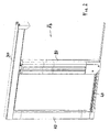
Figure 1 , represents the mosquito-net mounted with horizontally sliding net, in a first solution without line. -
Figure 2 , represents the mosquito-net mounted with horizontally sliding net, in a second solution, with side oscillation containing line. -
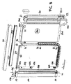
Figure 3 is the mosquito-net ofFigure 1 in an exploded view; -
Figure 4 is the mosquito-net ofFigure 2 in an exploded view; - Finally,
figure 5 is an exploded view of main components of the mosquito-net ofFigure 1 and2 , respectively; handlebar, roller, driving device, and net-guiding chain. - With reference to
figures 1 and2 the mosquito-net 1a, 1 b, includes at least: a side and verticalroller shutter box 10 that contains aroller 100 of the net orscreen 200, a ;handlebar 20, a fixedupper guide 30 and a lower net-guidingchain 40. - Inside the
roller shutter box 10, made up of a box-like element, metallic, closed by a base 11 and ahead 12, the roller 100 (figs. 3 ,4 ) is longitudinally housed, with the related net orscreen 200. The net orscreen 200 is with a first end joined to saidroller 100 around which it is wound, then turned exiting sideways from theroller shutter box 10 by means of the coming and going movement, along the horizontal axis of thehandlebar 20 to which said net 200 is vertically joined with the second end. Theupper end 21 of thehandlebar 20 is driven by theupper guide 30, horizontal, that is fixed at the lintel of the architectonic opening, while thelower end 22 is configured so as to lay down, with the participation of the driving device, the net-guidingchain 40 that also slides inside and along thehandlebar 20. The function of the net-guidingchain 40 is particularly to hold and drive during its distending, after the movement of thehandlebar 20, thelower border 201 of the net 200, while thetop edge 202 of the net 200 slides and remains inside theupper guide 30. - The
roller 100 that is vertically contained inside theroller shutter box 10, comprises (figures 3 ,4 and5 ) of a cylindrical pipe, on the surface of which it clamps the first end of the net 200. Inside the pipe there is aspiral spring 102, coaxial to asleeve 103, thisspiral spring 102 on one side is joined to a key 104 that is attached along the inside wall of the cylindrical pipe, on the other exiting from thesleeve 103, engaging ashaft 105, with a gear-wheel 106 keyed on the top. Theroller 100, is thus introduced inside theroller shutter box 10 and is held in vertical position by means of the base 11 and head 12 (figure 3 ) that close the two ends, respectively lower and upper, of theroller shutter box 10. - The base 11, besides closing the lower end of the
roller shutter box 10, allowing pivoting by means of thepin 110 of theroller 100 closed by thehead 107, is provided with two side appendixes 111 (figure 3 and4 ) to the which thefirst end 400 of the net-guiding chain 40 (figure 5 ) is engaged . The head 12 (figure 3 and4 ) that is applied on the upper part of theroller shutter box 10 is shaped with arecess 120 inside of which the gear-wheel 106 is housed that is connected with thespiral spring 102. - The driving device (
figure 5 ) of the net-guidingchain 40 includes the gear-wheel 106, which engages thechain 50 made up at least for a part by a number of balls one after another with thefirst end 51 that is engaged at theupper end 21 of thehandlebar 20. Thechain 50 that originates from thehandlebar 20 runs along and inside theupper guide 30, carries out a geared first turn around the gear-wheel 106, and then by means of apulley 60 hinged in theupper end 21 of thehandlebar 20 is transmitted towards thelower end 22 of thehandlebar 20. At thelower end 22 of thehandlebar 20 thepulley 61 is hinged around which the rope portion of thechain 50 rotates to be forced upwards to turn around the pulley 62 that is hinged to the head module 41 of the net-guidingchain 40, then again transmitted downwards in such a way that thesecond end 52 fixes at thelower end 22 of thehandlebar 20. In this case, the net-guidingchain 40 consists of a series of modules 41, one hinged to another, in such a way as to result reciprocally concatenated, and slides longitudinally guided inside thehandlebar 20 that is hollow. Arope 70 is placed along the fixedupper guide 30 with afirst end 71 engaged at theend 301 of the fixedupper guide 30 and with thesecond end 72 transmitted by means of the pulley 63 hinged on the top 21 of thehandlebar 20 downwards, to be engaged to the head module 41 of the net-guidingchain 40. - The
handlebar 20 at thelower end 22 is shaped to provide acurved guide 220 accessible through the removal of acover 221 along which the net-guidingchain 40 is transmitted to scroll along thehandlebar 20. - In the solution of
figure 1 and3 , the mosquito-net 1a is shown only with the lower net-guidingchain 40 that is de-placed on the lower plane of the architectonic opening, holding only thelower edge 201 of the net 200, each module 41 on the upper part being configured in such a way as to provide acontinuous seat 410 inside of which saidlower edge 201 of the net 200 is longitudinally housed. As regards, the solution offigures 2 and4 , the mosquito-net 1 b suitable for a mosquito-net of particular width, provides the combination of a thinrectilinear line 80, applied along the plane of the architectonic opening, along which lays the net-guidingchain 40, whose thickness is less than 3mm, in this case with a tolerance of ±0.2mm. In this case the function of the net-guidingchain 40 is also to prevent the possible side oscillation of said net 200 and of the net-guidingchain 40, each module 41 being provided with a lower corresponding seat, in such a way as to obtain a continuous seat 411, that develops for the whole length of the net-guidingchain 40. The seat 411 then substantially straddles thethin line 80 with theparallel walls 412, at the longitudinal edges of thethin line 80. In this way the alignment of the net-guidingchain 40 is also assured, simplified by the possible presence of a sliding guide placed at thelower end 22 of thehandlebar 20. -
- 1 a, 1 b, mosquito-net
- 10 side and vertical roller shutter box
- 100 roller
- 102 spiral spring
- 103 sleeve
- 104 key
- 105 shaft
- 106 gear-wheel
- 200 net or screen
- 201 lower edge
- 202 upper edge
- 20 handlebar
- 21 upper end
- 22 lower end
- 220 curved guide
- 221 cover
- 300 fixed upper guide
- 301 end
- 40 lower net-guiding chain
- 41 head module
- 400 first end
- 410 continuous upper seat
- 411 continuous lower seat
- 412 parallel walls
- 11 base
- 110 pin
- 111 side appendixes
- 12 head
- 120 recess
- 107 head
- 50 chain
- 51 first end
- 52 second end
- 60 pulley
- 61 pulley
- 62 pulley
- 63 pulley
- 70 rope
- 71 first end
- 72 second end
- 80 thin line
Claims (8)
- Mosquito-net with rollaway net-guiding chain for net with horizontal sliding, characterised in that it consists of:a) a vertical roller shutter box 100, lateral as compared to a horizontal and fixed upper guide 30, containing the roller 100 of the net 200; the net 200 is joined with a first end to the roller 100;b) a horizontal and fixed upper guide 30 joined with one end at the upper end of the vertical roller shutter box 100;c) a vertical handlebar 20 to which the second end of the net 200 is joined; the handlebar 20 being with the upper end 21 constrained to the fixed guide 30 and mobile longitudinally as to the said fixed guide 30;d) a net-guiding chain 40 with containing seat 410 of the lower border 201 of the net 200; the net-guiding chain 40 consisting of modular elements 41 reciprocally interconnected, where said net-guiding chain 40 is with a first end 400 engaged at the lower end of the roller shutter box 100, while the second end slides inside the handlebar 20;e) a driving device of the net-guiding chain 40, comprising at least a rope 70, chain 50, and relative transmission means placed at least at the handlebar 20 and the roller shutter box 10.
- Mosquito-net with rollaway net-guiding chain for net with horizontal sliding, according to claim 1, characterised in that the net-guiding chain 40 consisting of a series of modules 41 one hinged to the other in a removable manner, resulting reciprocally concatenated, that slides longitudinally guided inside the hollow handlebar 20, is provided with upper seat 410 inside of which the lower border 201 of the net 200 is housed in an engaged manner.
- Mosquito-net with rollaway net-guiding chain for net with horizontal sliding, according to claim 1, characterised in that the roller 100 of the net 200 contained in the roller shutter box 10 includes a charging spring 102, and a gear-wheel 106.
- Mosquito-net with rollaway net-guiding chain for net with horizontal sliding, according to claims 1 and 2, characterised in that the driving device of the net-guiding chain 40 is composed of:- gear-wheel 106 that engages the chain 50 with the first end 51 engaged at the upper end 21 of the handlebar 20; the chain 50 that originates from the handlebar 20 runs along and inside the upper guide 30, carries out a first turn geared around the gear-wheel 106, and by means of a pulley 60 hinged in the upper end 21 of the handlebar 20 is transmitted towards the lower end 22 of the handlebar 20 where the pulley 61 is hinged around which the rope portion of the chain 50 rotates to be forced upwards to turn around the pulley 62 that is hinged to the head module 41 of the net-guiding chain 40, then again transmitted downwards in such a way that the second end 52 fixes at the lower end 22 of the handlebar 20;- rope 70 situated along the fixed upper guide 30, with a first end 71 engaged at the end 301 of the fixed upper guide 30 and with the second end 72 transmitted by means of the pulley 63 hinged on the top 21 of the handlebar 20 downwards, fixed to the head module 41 of the net-guiding chain 40.
- Mosquito-net with rollaway net-guiding chain for net with horizontal sliding, according to the previous claims, characterised in that the base 11 shuts the lower ends of the roller shutter box 10, and by means of the pin 110, hinges the roller 100 closed by the head 107; said base 11 provided with two side appendixes 111 to which the first end 400 of the net-guiding chain 40 is engaged.
- Mosquito-net with rollaway net-guiding chain for net with horizontal sliding, according to the previous claims, characterised in that the head 12 is shaped with a recess 120 inside of which the gear-wheel 106 is housed that is connected with the spiral spring 102.
- Mosquito-net with rollaway net-guiding chain for net with horizontal sliding, according to the previous claims, characterised in that it requires the thin line 80, applied along the plane of the architectonic opening, along which the net-guiding chain 40 is situated, said thin line 80 being between 1 mm and 3mm thick, with a tolerance of ±0.2mm.
- Mosquito-net with rollaway net-guiding chain for net with horizontal sliding, according to the previous claims, characterised in that each module 41 of the net-guiding chain 40 has below one corresponding seat, in such a way as to obtain a continuous seat 411, that develops for the whole length of the net-guiding chain 40, said seat 411 substantially straddling the thin line 80 with the parallel walls 412, at the longitudinal edges of the thin line 80.
Applications Claiming Priority (1)
| Application Number | Priority Date | Filing Date | Title |
|---|---|---|---|
| IT000020A ITTV20080020A1 (en) | 2008-02-01 | 2008-02-01 | MOSQUITO NET WITH CHAIN YOU WILL HAVE A RETRACTABLE FOR HORIZONTAL SLIDING NETWORK. |
Publications (2)
| Publication Number | Publication Date |
|---|---|
| EP2085562A2 true EP2085562A2 (en) | 2009-08-05 |
| EP2085562A3 EP2085562A3 (en) | 2012-09-19 |
Family
ID=40292031
Family Applications (1)
| Application Number | Title | Priority Date | Filing Date |
|---|---|---|---|
| EP09001215A Withdrawn EP2085562A3 (en) | 2008-02-01 | 2009-01-29 | Mosquito-net with rollaway net-guiding chain for net with horizontal sliding |
Country Status (2)
| Country | Link |
|---|---|
| EP (1) | EP2085562A3 (en) |
| IT (1) | ITTV20080020A1 (en) |
Cited By (13)
| Publication number | Priority date | Publication date | Assignee | Title |
|---|---|---|---|---|
| ITTV20090199A1 (en) * | 2009-10-09 | 2011-04-10 | Bettio Group Sas Di Bettio Denis & C | STEERING CABLE GUIDE SYSTEM TO MOVE THE NETWORK WITH BAR HORIZONTAL SLIDING HANDLE IN A MOSQUITO NET WITH DRIVING NETWORK DRIVING CHAIN. |
| ITMI20101138A1 (en) * | 2010-06-23 | 2011-12-24 | Antonino Crupi | MOSQUITO NET FOR ARCH OPENING. |
| ITBO20110442A1 (en) * | 2011-07-26 | 2013-01-27 | Mv Line Spa | GROUP OF MOVEMENT FOR MOSQUITO NETS, CURTAINS AND LAMINAR ELEMENTS IN GENERAL |
| ES2401790A1 (en) * | 2011-06-03 | 2013-04-24 | Orozco Herrero, S.L. | Device for guiding a piece of fabric |
| ITBO20110614A1 (en) * | 2011-11-02 | 2013-05-03 | Mv Line Spa | MOVABLE MOSQUITO NET, PARTICULARLY FOR WINDOWS, DOORS AND THE LIKE. |
| EP2746524A1 (en) * | 2012-12-20 | 2014-06-25 | EFFE S.r.l. | Motorized screen group |
| WO2015079267A1 (en) * | 2013-11-28 | 2015-06-04 | Ideco Industrial S.A. | Anti-mosquito net system for fixed and articulated lower guide |
| ITUA20161655A1 (en) * | 2016-03-15 | 2017-09-15 | Giuseppe Forciniti | SHIELD FOR LATERAL SLIDING DOORS WITH LOWER GUIDE TO CART |
| US20180305976A1 (en) * | 2015-11-24 | 2018-10-25 | Metaco, Inc. | Electric screen device |
| CN110644915A (en) * | 2019-09-24 | 2020-01-03 | 安徽省唯一纺织有限公司 | Screen door |
| IT201900002879A1 (en) * | 2019-02-28 | 2020-08-28 | Luca Buggio | TENSIONING DEVICE FOR MOSQUITO NETS AND ROLLING BLINDS |
| EP4047172A1 (en) * | 2021-02-17 | 2022-08-24 | Hendrikus Antonius Maria Bouhuis | Screen door control device for automatic opening and closing of a screen door |
| US11505990B2 (en) * | 2018-02-26 | 2022-11-22 | Argyrios Papadopoulos | Autonomous anti-mosquito net system for a fixed lower guide |
Families Citing this family (2)
| Publication number | Priority date | Publication date | Assignee | Title |
|---|---|---|---|---|
| EP3056650B1 (en) | 2015-02-13 | 2017-06-21 | Bettio Service Spa | Insect screen with a driving device of the net guiding chain and system for facilitating assembly and for correcting the positioning arrangement |
| IT202100007952A1 (en) | 2021-03-31 | 2022-10-01 | Bettio Flyscreens S R L | HORIZONTAL SLIDING MOSQUITO SCREEN EQUIPPED WITH DEVICES TO FACILITATE ASSEMBLY AND ADJUSTMENT OF THE POSITIONING SET-UP |
Citations (4)
| Publication number | Priority date | Publication date | Assignee | Title |
|---|---|---|---|---|
| JPS5351648A (en) | 1976-10-21 | 1978-05-11 | Sato Shigeo | Temperature control element |
| JPH06158961A (en) | 1992-11-26 | 1994-06-07 | Sanwa Shutter Corp | Window screen device |
| EP0753642A2 (en) | 1995-07-14 | 1997-01-15 | Metaco Inc. | Screen apparatus |
| EP0999335A1 (en) | 1998-11-06 | 2000-05-10 | Metaco Inc. | Screen device |
Family Cites Families (3)
| Publication number | Priority date | Publication date | Assignee | Title |
|---|---|---|---|---|
| JP4109573B2 (en) * | 2003-05-21 | 2008-07-02 | セイキ販売株式会社 | Retractable screen device |
| JP4084327B2 (en) * | 2004-03-30 | 2008-04-30 | セイキ販売株式会社 | Screen device |
| CA2633877C (en) * | 2005-12-12 | 2014-03-25 | Centor Australia Pty Ltd | A pull across roll up screen assembly |
-
2008
- 2008-02-01 IT IT000020A patent/ITTV20080020A1/en unknown
-
2009
- 2009-01-29 EP EP09001215A patent/EP2085562A3/en not_active Withdrawn
Patent Citations (4)
| Publication number | Priority date | Publication date | Assignee | Title |
|---|---|---|---|---|
| JPS5351648A (en) | 1976-10-21 | 1978-05-11 | Sato Shigeo | Temperature control element |
| JPH06158961A (en) | 1992-11-26 | 1994-06-07 | Sanwa Shutter Corp | Window screen device |
| EP0753642A2 (en) | 1995-07-14 | 1997-01-15 | Metaco Inc. | Screen apparatus |
| EP0999335A1 (en) | 1998-11-06 | 2000-05-10 | Metaco Inc. | Screen device |
Cited By (18)
| Publication number | Priority date | Publication date | Assignee | Title |
|---|---|---|---|---|
| EP2312113A1 (en) * | 2009-10-09 | 2011-04-20 | BETTIO GROUP SAS di Bettio Denis & C. | Cable arrangement for actuating a horizontally sliding mosquito screen |
| ITTV20090199A1 (en) * | 2009-10-09 | 2011-04-10 | Bettio Group Sas Di Bettio Denis & C | STEERING CABLE GUIDE SYSTEM TO MOVE THE NETWORK WITH BAR HORIZONTAL SLIDING HANDLE IN A MOSQUITO NET WITH DRIVING NETWORK DRIVING CHAIN. |
| ITMI20101138A1 (en) * | 2010-06-23 | 2011-12-24 | Antonino Crupi | MOSQUITO NET FOR ARCH OPENING. |
| EP2400105A1 (en) * | 2010-06-23 | 2011-12-28 | Antonio Trotta | Mosquito net for arc-like opening |
| EP2530236A3 (en) * | 2011-06-03 | 2014-09-03 | Orozco Herrero, S.L. | Device for guiding a piece of fabric |
| ES2401790A1 (en) * | 2011-06-03 | 2013-04-24 | Orozco Herrero, S.L. | Device for guiding a piece of fabric |
| ITBO20110442A1 (en) * | 2011-07-26 | 2013-01-27 | Mv Line Spa | GROUP OF MOVEMENT FOR MOSQUITO NETS, CURTAINS AND LAMINAR ELEMENTS IN GENERAL |
| ITBO20110614A1 (en) * | 2011-11-02 | 2013-05-03 | Mv Line Spa | MOVABLE MOSQUITO NET, PARTICULARLY FOR WINDOWS, DOORS AND THE LIKE. |
| WO2013064308A1 (en) * | 2011-11-02 | 2013-05-10 | Mv Line S.P.A. | Movable mosquito screen, particularly for windows, doors and the like |
| EP2746524A1 (en) * | 2012-12-20 | 2014-06-25 | EFFE S.r.l. | Motorized screen group |
| WO2015079267A1 (en) * | 2013-11-28 | 2015-06-04 | Ideco Industrial S.A. | Anti-mosquito net system for fixed and articulated lower guide |
| US20180305976A1 (en) * | 2015-11-24 | 2018-10-25 | Metaco, Inc. | Electric screen device |
| US10822868B2 (en) * | 2015-11-24 | 2020-11-03 | Metaco, Inc. | Electric screen device |
| ITUA20161655A1 (en) * | 2016-03-15 | 2017-09-15 | Giuseppe Forciniti | SHIELD FOR LATERAL SLIDING DOORS WITH LOWER GUIDE TO CART |
| US11505990B2 (en) * | 2018-02-26 | 2022-11-22 | Argyrios Papadopoulos | Autonomous anti-mosquito net system for a fixed lower guide |
| IT201900002879A1 (en) * | 2019-02-28 | 2020-08-28 | Luca Buggio | TENSIONING DEVICE FOR MOSQUITO NETS AND ROLLING BLINDS |
| CN110644915A (en) * | 2019-09-24 | 2020-01-03 | 安徽省唯一纺织有限公司 | Screen door |
| EP4047172A1 (en) * | 2021-02-17 | 2022-08-24 | Hendrikus Antonius Maria Bouhuis | Screen door control device for automatic opening and closing of a screen door |
Also Published As
| Publication number | Publication date |
|---|---|
| ITTV20080020A1 (en) | 2009-08-02 |
| EP2085562A3 (en) | 2012-09-19 |
Similar Documents
| Publication | Publication Date | Title |
|---|---|---|
| EP2085562A2 (en) | Mosquito-net with rollaway net-guiding chain for net with horizontal sliding | |
| EP2085563A1 (en) | Mosquito-net with net-guiding chain driving device for net with horizontal sliding | |
| US6899380B2 (en) | Sunshade for a motor vehicle roof | |
| DE69233107T2 (en) | pleated shade | |
| EP2312113A1 (en) | Cable arrangement for actuating a horizontally sliding mosquito screen | |
| KR20170038469A (en) | roll screen device | |
| RU2304683C2 (en) | Door assembly | |
| DE2906871C2 (en) | ||
| US20100116448A1 (en) | Tensioning system for retractable screens and shades | |
| EP2294275B1 (en) | Roller shutter having a driving means and a driving element in form of a toothed belt | |
| EP3056650B1 (en) | Insect screen with a driving device of the net guiding chain and system for facilitating assembly and for correcting the positioning arrangement | |
| DE102008036742A1 (en) | Roller shutters for a skylight | |
| ES2662576T3 (en) | Element for moving mosquito nets, curtains and the like | |
| ES2328385T3 (en) | DEVICE FOR THE OPENING AND CLOSURE OF A WINDOW OR DOOR MOUNTED SLIDING ON A FRAME. | |
| CN102421981A (en) | Screen fittings | |
| US20060137830A1 (en) | Winding mechanism of blind | |
| DE202013012570U1 (en) | roller blind | |
| DE102009035426B4 (en) | Roller blind arrangement, in particular for a vehicle, and roof arrangement | |
| DE202004020095U1 (en) | Automotive sunscreen blind is deployed by hand from upright cassette along guide rails | |
| DE3225099A1 (en) | Shutting-off device | |
| US8307876B2 (en) | Garage door/track/coupler system | |
| DE3910998A1 (en) | Roller blind | |
| JP5207397B2 (en) | Curtain opening and closing device | |
| KR101667497B1 (en) | Winder type screen door | |
| JP2521790Y2 (en) | Screen opening and closing device |
Legal Events
| Date | Code | Title | Description |
|---|---|---|---|
| PUAI | Public reference made under article 153(3) epc to a published international application that has entered the european phase |
Free format text: ORIGINAL CODE: 0009012 |
|
| AK | Designated contracting states |
Kind code of ref document: A2 Designated state(s): AT BE BG CH CY CZ DE DK EE ES FI FR GB GR HR HU IE IS IT LI LT LU LV MC MK MT NL NO PL PT RO SE SI SK TR |
|
| AX | Request for extension of the european patent |
Extension state: AL BA RS |
|
| 17P | Request for examination filed |
Effective date: 20100115 |
|
| RAP1 | Party data changed (applicant data changed or rights of an application transferred) |
Owner name: BETTIO SERVICE SPA |
|
| PUAL | Search report despatched |
Free format text: ORIGINAL CODE: 0009013 |
|
| AK | Designated contracting states |
Kind code of ref document: A3 Designated state(s): AT BE BG CH CY CZ DE DK EE ES FI FR GB GR HR HU IE IS IT LI LT LU LV MC MK MT NL NO PL PT RO SE SI SK TR |
|
| AX | Request for extension of the european patent |
Extension state: AL BA RS |
|
| RIC1 | Information provided on ipc code assigned before grant |
Ipc: E06B 9/54 20060101ALI20120816BHEP Ipc: E06B 9/52 20060101AFI20120816BHEP |
|
| AKX | Designation fees paid |
Designated state(s): AT BE BG CH CY CZ DE DK EE ES FI FR GB GR HR HU IE IS IT LI LT LU LV MC MK MT NL NO PL PT RO SE SI SK TR |
|
| STAA | Information on the status of an ep patent application or granted ep patent |
Free format text: STATUS: THE APPLICATION IS DEEMED TO BE WITHDRAWN |
|
| 18D | Application deemed to be withdrawn |
Effective date: 20150801 |