EP2085271A1 - Airbag device - Google Patents
Airbag device Download PDFInfo
- Publication number
- EP2085271A1 EP2085271A1 EP08166647A EP08166647A EP2085271A1 EP 2085271 A1 EP2085271 A1 EP 2085271A1 EP 08166647 A EP08166647 A EP 08166647A EP 08166647 A EP08166647 A EP 08166647A EP 2085271 A1 EP2085271 A1 EP 2085271A1
- Authority
- EP
- European Patent Office
- Prior art keywords
- airbag
- lid
- lid cover
- airbag device
- cover
- Prior art date
- Legal status (The legal status is an assumption and is not a legal conclusion. Google has not performed a legal analysis and makes no representation as to the accuracy of the status listed.)
- Granted
Links
- 230000002093 peripheral effect Effects 0.000 claims description 12
- 239000000463 material Substances 0.000 description 8
- 239000002828 fuel tank Substances 0.000 description 4
- IJGRMHOSHXDMSA-UHFFFAOYSA-N Atomic nitrogen Chemical compound N#N IJGRMHOSHXDMSA-UHFFFAOYSA-N 0.000 description 3
- 230000000994 depressogenic effect Effects 0.000 description 3
- 229910001873 dinitrogen Inorganic materials 0.000 description 3
- 241000237983 Trochidae Species 0.000 description 2
- 239000003795 chemical substances by application Substances 0.000 description 2
- 239000004677 Nylon Substances 0.000 description 1
- 238000004140 cleaning Methods 0.000 description 1
- 238000006073 displacement reaction Methods 0.000 description 1
- 230000002708 enhancing effect Effects 0.000 description 1
- 239000004744 fabric Substances 0.000 description 1
- 239000000945 filler Substances 0.000 description 1
- 239000000446 fuel Substances 0.000 description 1
- 230000010354 integration Effects 0.000 description 1
- 238000000034 method Methods 0.000 description 1
- 229920001778 nylon Polymers 0.000 description 1
- 230000002265 prevention Effects 0.000 description 1
- 230000003584 silencer Effects 0.000 description 1
Images



Classifications
-
- B—PERFORMING OPERATIONS; TRANSPORTING
- B60—VEHICLES IN GENERAL
- B60R—VEHICLES, VEHICLE FITTINGS, OR VEHICLE PARTS, NOT OTHERWISE PROVIDED FOR
- B60R21/00—Arrangements or fittings on vehicles for protecting or preventing injuries to occupants or pedestrians in case of accidents or other traffic risks
- B60R21/02—Occupant safety arrangements or fittings, e.g. crash pads
- B60R21/16—Inflatable occupant restraints or confinements designed to inflate upon impact or impending impact, e.g. air bags
-
- B—PERFORMING OPERATIONS; TRANSPORTING
- B62—LAND VEHICLES FOR TRAVELLING OTHERWISE THAN ON RAILS
- B62J—CYCLE SADDLES OR SEATS; AUXILIARY DEVICES OR ACCESSORIES SPECIALLY ADAPTED TO CYCLES AND NOT OTHERWISE PROVIDED FOR, e.g. ARTICLE CARRIERS OR CYCLE PROTECTORS
- B62J27/00—Safety equipment
- B62J27/20—Airbags specially adapted for motorcycles or the like
-
- B—PERFORMING OPERATIONS; TRANSPORTING
- B60—VEHICLES IN GENERAL
- B60R—VEHICLES, VEHICLE FITTINGS, OR VEHICLE PARTS, NOT OTHERWISE PROVIDED FOR
- B60R21/00—Arrangements or fittings on vehicles for protecting or preventing injuries to occupants or pedestrians in case of accidents or other traffic risks
- B60R2021/0065—Type of vehicles
- B60R2021/0088—Cycles, e.g. motorcycles
Definitions
- the present invention relates to an airbag device for a vehicle such as a motorcycle or four-wheeled vehicle.
- the airbag device includes an inflator, an airbag, and a module cover.
- the inflator and the airbag are accommodated in a casing provided on the vehicle body.
- the module cover openably covers a top opening of the casing, thereby hiding the inflator and the airbag.
- the module cover includes a tear line. When the airbag is deployed, the module cover is torn along the tear line to be forwardly opened by being pushed by the deploying airbag, thereby allowing the airbag to be deployed further (see Patent Document 1). JP-A No. 2007-69792
- the module cover makes up a vehicle body exterior, so that there can be cases where it is difficult to secure exterior design integrity between the module cover and other exterior parts of the vehicle body. Furthermore, to allow the module cover to make up a vehicle body exterior while being capable of appropriate opening movement, it is necessary to design the module cover differently for different models of motorcycles. This reduces the applicability of the airbag device.
- An object of the present invention is to provide an airbag device which, while excelling in applicability, can improve exterior design integrity between the airbag device and a vehicle body exterior.
- an airbag device comprising a case (for example, the case 53 of the following embodiment) which accommodates an airbag (for example, the airbag 51 of the following embodiment) and an inflator (for example, the inflator 52 of the following embodiment), a lid (for example, the lid 62 of the following embodiment) which, when the airbag deploys, releases a side of the case, and a lid cover (for example, the lid cover 70 of the following embodiment) for covering the lid.
- a case for example, the case 53 of the following embodiment
- an airbag for example, the airbag 51 of the following embodiment
- an inflator for example, the inflator 52 of the following embodiment
- a lid for example, the lid 62 of the following embodiment
- a lid cover for example, the lid cover 70 of the following embodiment
- Designing a lid cover which is to make up an exposed exterior part of a vehicle body requires consideration to be made to prevent sink lines from being formed on the lid cover and also to secure integrity, in terms of both material and exterior design, between the lid cover and other exterior parts of the vehicle body.
- the lid cover structured as in the above invention requires no such consideration to be made, so that the lid cover is only required to be capable of being released when the airbag is deployed.
- the lid cover makes up an exterior design of a vehicle. It is, therefore, possible to form the lid cover using a material similar to that of other exterior parts of the vehicle body separately from the lid closely related with the deploying function of the airbag.
- the lid cover is structured to be easily released from a peripheral part (for example, the fixing seat 77 of the following embodiment) when the airbag deploys. Therefore, the lid cover does not hinder the opening movement of the lid.
- the lid cover is provided with a fixture part for fixation to a peripheral part, the fixture part having a fragile portion. It is, therefore, possible, by adjusting the fragile portion, to adjust the way the lid cover opens when the lid is opened by the deploying airbag.
- the lid cover is forwardly openable along a forward direction of the vehicle. This allows the airbag to be deployed effectively.
- an exterior surface of the lid cover makes up a panel section (for example, the panel section 32a or top shell 32 of the following embodiment) positioned rearward of a handlebar (for example, the handlebar 43 of the following embodiment) and forward of a seat (for example, the front seat 27 of the following embodiment) of a motorcycle (for example, the motorcycle 1 of the following embodiment). In this arrangement, the lid cover does not spoil the appearance of the conspicuous exterior portion of the motorcycle.
- the lid cover itself can be formed of an exterior member of the vehicle body. Therefore, unlike in cases where a lid is exposed on the vehicle body, the lid cover can be designed without giving consideration for the prevention of sink line generation or for securing integration, in terms of both material and exterior design, between the lid cover and other exterior parts of the vehicle. Namely, the lid cover is only required to be capable of being released when the airbag is deployed. Thus, integrity between the lid cover and other exterior parts of the vehicle can be easily secured without special consideration. Furthermore, the case and the lid can be commonly used for different models of motorcycles, enhancing the applicability of the airbag device.
- the lid cover can be formed of a material similar to that of other exterior parts of the vehicle body separately from the lid closely related with the deploying function of the airbag. This facilitates improving the external appearance quality of the motorcycle.
- the lid cover does not hinder the opening movement of the lid, so that the airbag can be deployed smoothly.
- the airbag can hold the occupant.
- the lid cover does not spoil the appearance of the conspicuous exterior portion of the motorcycle, and allows the external appearance quality of the motorcycle to be improved.
- a front wheel 2 of a motorcycle 1 is journaled to a lower end portion of a pair of left and right front forks 3.
- An upper portion of each of the front forks 3 is steerably connected, via a steering system 4, to a head pipe 6 provided in a front end portion of a body frame 5.
- a handlebar 43 for steering the front wheel is attached to an upper portion of the steering system 4.
- a pair of left and right main frames 7 extend downwardly and rearwardly from the head pipe 6.
- a water-cooled, 4-stroke, horizontally-opposed six-cylinder engine 10 as a prime mover for the motorcycle 1 is mounted below the main frames 7.
- a front end portion of a swing arm 11 to which a rear wheel 9 is journaled is swingably connected to a pivot plate 8 connected to a rear end portion of each of the main frames 7.
- the swing arm 11 is of a hollow one-sided type, and the rear wheel 9 is journaled to a rear end portion thereof.
- a drive shaft, not shown, extending from the engine 10 is inserted through the one-sided swing arm. Power generated by the engine 10 is transmitted to the rear wheel 9 via the drive shaft and a gear box 12 disposed in a central portion of the rear wheel.
- a front portion of a seat frame 14 supporting front and rear seats 27 and 28 for occupants is joined to near the pivot plate 8.
- the front seat 27 is for a rider.
- the rear seat 28 is for a pillion passenger.
- the front seat 27 includes a front seat body 27a and a backrest 27b.
- the rear seat 28 includes a rear seat body 28a and a seat back 28b.
- the front and rear seat bodies 27a and 28a are integrally formed, and the backrest 27b is disposed between them.
- a rear trunk 29 is disposed behind the rear seat body 28a.
- the seat back 28b is positioned in front of the rear trunk 29.
- a fuel tank 30 and an air cleaner box 31 for cleaning intake air are disposed forwardly of the front seat 27 with the fuel tank 30 extending to below the front seat 27. These parts are covered by a top shelter 32 which is an exterior part.
- a large front cowl 34 provided with a pair of left and right headlamps 33 is disposed in a front body portion of the motorcycle 1.
- a large windscreen 35 is provided above a front portion of the front cowl 34.
- a meter panel 36 provided with, for example, a speedometer and a tachometer is disposed on a rear side of an upper portion of the front cowl 34.
- the top shelter 32 extending downwardly and rearwardly of the meter panel 36 covers a motorcycle body portion ranging from the rear side of the front cowl 34 to the front seat 27.
- Left and right mirrors 38 each provided with a front winker 37 are attached to both sides of an upper portion of the front cowl 34.
- a radiator 39 for the engine is disposed laterally inwardly of the front cowl 34 (inwardly in the vehicle width direction), the radiator 39 being oriented approximately perpendicularly to the lateral direction of the motorcycle.
- Left and right saddle bags 40 are disposed on both sides below the rear seat 28 and rear trunk 29.
- Rear combination lamps 41 each of which functions as tail lamps, brake lamps, and rear winkers are disposed on both sides of a rear portion of the left and right saddle bags 40 and both sides of a rear portion of the rear trunk 29.
- a silencer 42 for engine exhaust is disposed downwardly of each of the left and right saddle bags 40.
- the top shelter 32 is provided with an openable/closable shelter lid 44 disposed in front of the front seat 27.
- the shelter lid 44 allows fuel to be fed to the internal fuel tank through a filler opening of the fuel tank.
- a panel section 32a is formed in front of the shelter lid 44 to be rearward of a handlebar 43 and forward of the front seat 27.
- the panel section 32a has a cut-out portion 44a in which an airbag device 50 is disposed.
- the top shelter 32 may be provided with a depressed part, and the airbag device 50 may be disposed in the depressed part, or such a depressed part to accommodate the airbag device 50 may be provided in the panel section 32a.
- Fig. 4 is an exploded perspective view of the airbag device.
- Figs. 5 to 8 each show the airbag device schematically.
- the airbag device 50 has a case 53 which accommodates an airbag 51 and an inflator 52.
- the case 53 is shaped like a rectangular box having an open top, left and right sidewalls 54, front wall 55, rear wall 56, and bottom wall 57.
- a bracket 58 to be fixed to the body frame 5 is fixed to each of the sidewalls 54.
- the bracket 58 varies in type between different models of motorcycles.
- Fixing holes 60 for rivets 80 are formed in an upper portion of each of the front wall 55, rear wall 56, and side walls 54.
- the number of the fixing holes 60 formed in each of the front wall 55 and rear wall 56 is, for example, three.
- the number of the fixing holes 60 formed in each of the side walls 54 is, for example, two.
- Two pins 61 are provided in a lower portion of the front wall 55.
- the airbag 51 is made of, for example, nylon cloth.
- the inflator 52 is provided with an electric igniter, an ignition agent, and a nitrogen gas generating agent.
- the airbag 51 accommodated in the case 53 may be attached with one end of a belt member, not shown, the other end of which is attached to the vehicle body. In such an arrangement, when the airbag 51 is deployed, the belt member can keep the airbag 51 in an appropriate position.
- the open top of the case 53 is fixedly covered by the lid 62 such that the lid 62 is released when the airbag 51 is deployed.
- the lid 62 is a rectangular member having an upper wall 63, a front wall 64, side walls 65, and a rear wall 66, the upper wall 63 being surrounded by the other walls. It has fixing holes 67 corresponding to the fixing holes 60 for the rivets 80 provided in the case 53, i.e. three each of the fixing holes 67 in the front wall 64 and rear wall 66, and two each in the side walls 65.
- the upper wall 63 of the lid 62 includes a U-shaped tear line 68 formed of three portions with one portion extending along the rear wall of the lid 62 and the rest of two portions extending along the two side walls of the lid 62.
- the U-shaped portion i.e. an opening portion L, defined by the tear line 68 of the top wall 63 of the lid 62 is torn open along the tear line 68, allowing the airbag 51 to be deployed outward.
- a lid cover 70 is, like the top shelter 32 and panel section 32a, a member to make up the exterior design of the motorcycle 1, so that it is formed of, for example, a material similar to that of the panel section 32a to look harmonious with the panel section 32a.
- the lid cover 70 has an upper wall 72 and a peripheral wall 73 surrounding the upper wall 72 and extending diagonally downwardly.
- the peripheral wall 73 is, in a front edge portion thereof, provided with a pair of downwardly extending guide bars 74.
- the guide bars 74 each have a guide slot 75.
- the pins 61 of the case 53 are inserted through the guide slots 75, so that, when the airbag 51 is deployed, the lid cover 70 is guided to move upwardly.
- a peripheral portion of the peripheral wall 73 of the lid cover 70 is designed to cover a peripheral portion of the cut-out portion 44a of the top shelter 32 so that the cut-out portion 44a is not visible from outside.
- the peripheral wall 73 of the lid cover 70 has, in a middle portion of its rear edge, a fixture piece 71 having a screw hole 76.
- the fixture piece 71 is fixed, with a screw 78, to a fixing seat 77 provided on the vehicle body.
- a distance D is secured between the lid cover 70 and the lid 62.
- the distance D secures a space required to allow an initial opening movement of the opening portion L.
- the fixture piece 71 includes a tear line 79 formed in a base portion thereof. When receiving a load from below in deployment of the airbag 51, the fixture piece 71 is broken off along the tear line 79 and separated from the peripheral wall 73.
- the lid cover 70 When the fixture piece 71 is broken off the lid cover 70, the lid cover 70 is allowed to move up, relative to the case 53, being guided by the guide bars 74 and subsequently open forwardly (in the direction indicated by the arrows in Fig. 3 ) being led by its rear edge. As a result, the airbag 51 is allowed to inflate outward.
- the inflator 52 when a frontal collision of the motorcycle 1 is detected, the inflator 52 is caused, by an ignition current from an airbag controller, not shown, to generate, for example, nitrogen gas.
- the nitrogen gas enters the airbag 51 to deploy it.
- the lid 62 When, in an initial stage of inflation of the airbag 51, the lid 62 is pushed from below by the airbag 51 inflated in the case 53, the upper wall 63 of the lid 62 is torn along the tear line 68. This causes the opening portion L to forwardly open about a front portion thereof, allowing the airbag 51 to inflate outward.
- the lid cover 70 As the airbag 51 further deploys causing the opening portion L of the lid 62 and the airbag 51 to push the lid cover 70 from the back side, the lid cover 70 is subjected to an upward force which eventually causes the fixture piece 71 of the lid cover 70 to be broken off along the tear line 79. As a result, the fixture piece 71 is left attached only to the fixing seat 77 provided on the vehicle body, and the lid cover 70 is moved upward causing the pins 61 to relatively move along the guide slots 75 of the guide bars 74. This causes the lid cover 70 to further open forwardly (in the direction indicated by the arrows in Fig. 3 ) about a front end portion thereof, allowing the airbag 51 to further deploy. The airbag 51 thus deployed can absorb the forward displacement of the occupant.
- the lid cover 70 is only required to be capable of being released, when the airbag 51 deploys, by being pushed by the lid 62. Whereas the lid 62 including the tear line 68 is required to meet requirements in terms of its strength, rigidity, shape, and material so as to make the airbag 51 appropriately deployable, no such requirements are imposed on the lid cover 70. Therefore, the shape of the lid cover 70 can be designed, as an exterior part of the motorcycle 1, with higher flexibility; the lid cover 70 can be shaped not to cause the generation of sink lines; and the lid cover 70 can be formed of the same material as that of the panel section 32a. Thus, the lid cover 70 can be easily designed to be harmonious with the vehicle body design.
- the case 53, airbag 51, inflator 52, and lid 62 included in the airbag device 50 can be made common to different models of motorcycles. Therefore, to install the airbag device in different models of motorcycles, only the lid cover 70 and brackets 58 of the case 53 are required to be designed differently to suit different models of motorcycles. Thus, the airbag device has flexible applicability, being easily applicable to different models of motorcycles.
- the lid cover 70 is, like the top shelter 32 and panel section 32a, a member to make up the exterior design of the motorcycle 1. Therefore, unlike the lid 62 that is closely related with the deploying function of the airbag 51, the lid cover 70 can be formed of a material similar to that of the panel section 32a so as to improve the external appearance quality of the motorcycle. The lid cover 70 can be easily broken along the tear line 79, so that, when the airbag 51 is deployed, the lid cover 70 opens without fail not to hinder the deployment of the airbag 51.
- the fixture piece 71 of the lid cover 70 may be fixed to the rear wall 66 of the lid 62.
Landscapes
- Engineering & Computer Science (AREA)
- Mechanical Engineering (AREA)
- Air Bags (AREA)
Abstract
Description
- The present invention relates to an airbag device for a vehicle such as a motorcycle or four-wheeled vehicle.
- There has been a motorcycle equipped with an airbag device. The airbag device includes an inflator, an airbag, and a module cover. The inflator and the airbag are accommodated in a casing provided on the vehicle body. The module cover openably covers a top opening of the casing, thereby hiding the inflator and the airbag. The module cover includes a tear line. When the airbag is deployed, the module cover is torn along the tear line to be forwardly opened by being pushed by the deploying airbag, thereby allowing the airbag to be deployed further (see Patent Document 1).
JP-A No. 2007-69792 - In the above technique, however, the module cover makes up a vehicle body exterior, so that there can be cases where it is difficult to secure exterior design integrity between the module cover and other exterior parts of the vehicle body. Furthermore, to allow the module cover to make up a vehicle body exterior while being capable of appropriate opening movement, it is necessary to design the module cover differently for different models of motorcycles. This reduces the applicability of the airbag device.
- An object of the present invention is to provide an airbag device which, while excelling in applicability, can improve exterior design integrity between the airbag device and a vehicle body exterior.
- To address the above problem, the invention according to
Claim 1 provides an airbag device comprising a case (for example, thecase 53 of the following embodiment) which accommodates an airbag (for example, theairbag 51 of the following embodiment) and an inflator (for example, theinflator 52 of the following embodiment), a lid (for example, thelid 62 of the following embodiment) which, when the airbag deploys, releases a side of the case, and a lid cover (for example, thelid cover 70 of the following embodiment) for covering the lid.
Designing a lid cover which is to make up an exposed exterior part of a vehicle body requires consideration to be made to prevent sink lines from being formed on the lid cover and also to secure integrity, in terms of both material and exterior design, between the lid cover and other exterior parts of the vehicle body. The lid cover structured as in the above invention, however, requires no such consideration to be made, so that the lid cover is only required to be capable of being released when the airbag is deployed. - In the invention according to
Claim 2, the lid cover makes up an exterior design of a vehicle.
It is, therefore, possible to form the lid cover using a material similar to that of other exterior parts of the vehicle body separately from the lid closely related with the deploying function of the airbag. - In the invention according to
Claim 3, the lid cover is structured to be easily released from a peripheral part (for example, thefixing seat 77 of the following embodiment) when the airbag deploys.
Therefore, the lid cover does not hinder the opening movement of the lid. - In the invention according to Claim 4, the lid cover is provided with a fixture part for fixation to a peripheral part, the fixture part having a fragile portion.
It is, therefore, possible, by adjusting the fragile portion, to adjust the way the lid cover opens when the lid is opened by the deploying airbag. - In the invention according to
Claim 5, the lid cover is forwardly openable along a forward direction of the vehicle.
This allows the airbag to be deployed effectively.
In the invention according to Claim 6, an exterior surface of the lid cover makes up a panel section (for example, thepanel section 32a ortop shell 32 of the following embodiment) positioned rearward of a handlebar (for example, thehandlebar 43 of the following embodiment) and forward of a seat (for example, thefront seat 27 of the following embodiment) of a motorcycle (for example, themotorcycle 1 of the following embodiment).
In this arrangement, the lid cover does not spoil the appearance of the conspicuous exterior portion of the motorcycle. - According to the invention according to
Claim 1, the lid cover itself can be formed of an exterior member of the vehicle body. Therefore, unlike in cases where a lid is exposed on the vehicle body, the lid cover can be designed without giving consideration for the prevention of sink line generation or for securing integration, in terms of both material and exterior design, between the lid cover and other exterior parts of the vehicle. Namely, the lid cover is only required to be capable of being released when the airbag is deployed. Thus, integrity between the lid cover and other exterior parts of the vehicle can be easily secured without special consideration. Furthermore, the case and the lid can be commonly used for different models of motorcycles, enhancing the applicability of the airbag device.
According to the invention according toClaim 2, the lid cover can be formed of a material similar to that of other exterior parts of the vehicle body separately from the lid closely related with the deploying function of the airbag. This facilitates improving the external appearance quality of the motorcycle.
According to the invention according toClaim 3, the lid cover does not hinder the opening movement of the lid, so that the airbag can be deployed smoothly.
According to the invention according to Claim 4, it is possible, by adjusting the fragile portion, to adjust the way the lid cover opens when the lid is opened. That is, the fragile portion can be adjusted to allow the lid cover to open without fail.
According to the invention according toClaim 5, the airbag can hold the occupant.
According to the invention according to Claim 6, the lid cover does not spoil the appearance of the conspicuous exterior portion of the motorcycle, and allows the external appearance quality of the motorcycle to be improved. -
-
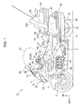
Fig. 1 is a side view of a motorcycle according to an embodiment of the invention. -
Fig. 2 is a plan view of the motorcycle according to the embodiment of the invention. -
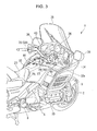
Fig. 3 is a perspective view of a front portion of the motorcycle according to the embodiment of the invention. -
Fig. 4 is an exploded perspective view of an airbag device according to the embodiment of the invention. -
Fig. 5 is a schematic front view of the airbag device according to the embodiment of the invention. -
Fig. 6 is a schematic right side view of the airbag device according to the embodiment of the invention. -
Fig. 7 is a schematic rear view of the airbag device according to the embodiment of the invention. -
Fig. 8 is a plan view of a lid according to the embodiment of the invention. - An embodiment of the present invention will be described below with reference to drawings. The directions front, rear, left, and right referred to in the following description are as seen in the forward direction of the motorcycle unless otherwise specified. In the attached drawings, arrows FR, LH, and UP represent the forward, leftward, and upward directions, respectively, of the vehicle.
- As shown in
Figs. 1 to 3 , afront wheel 2 of amotorcycle 1 is journaled to a lower end portion of a pair of left and rightfront forks 3. An upper portion of each of thefront forks 3 is steerably connected, via a steering system 4, to a head pipe 6 provided in a front end portion of abody frame 5. Ahandlebar 43 for steering the front wheel is attached to an upper portion of the steering system 4. A pair of left and right main frames 7 extend downwardly and rearwardly from the head pipe 6. A water-cooled, 4-stroke, horizontally-opposed six-cylinder engine 10 as a prime mover for themotorcycle 1 is mounted below the main frames 7. - A front end portion of a
swing arm 11 to which arear wheel 9 is journaled is swingably connected to apivot plate 8 connected to a rear end portion of each of the main frames 7. Theswing arm 11 is of a hollow one-sided type, and therear wheel 9 is journaled to a rear end portion thereof. A drive shaft, not shown, extending from theengine 10 is inserted through the one-sided swing arm. Power generated by theengine 10 is transmitted to therear wheel 9 via the drive shaft and agear box 12 disposed in a central portion of the rear wheel. - A front portion of a
seat frame 14 supporting front andrear seats pivot plate 8. Thefront seat 27 is for a rider. Therear seat 28 is for a pillion passenger. Thefront seat 27 includes afront seat body 27a and abackrest 27b. Therear seat 28 includes arear seat body 28a and a seat back 28b. The front andrear seat bodies backrest 27b is disposed between them. Arear trunk 29 is disposed behind therear seat body 28a. Theseat back 28b is positioned in front of therear trunk 29. Afuel tank 30 and an aircleaner box 31 for cleaning intake air are disposed forwardly of thefront seat 27 with thefuel tank 30 extending to below thefront seat 27. These parts are covered by atop shelter 32 which is an exterior part. - A
large front cowl 34 provided with a pair of left andright headlamps 33 is disposed in a front body portion of themotorcycle 1. Alarge windscreen 35 is provided above a front portion of thefront cowl 34. Ameter panel 36 provided with, for example, a speedometer and a tachometer is disposed on a rear side of an upper portion of thefront cowl 34. Thetop shelter 32 extending downwardly and rearwardly of themeter panel 36 covers a motorcycle body portion ranging from the rear side of thefront cowl 34 to thefront seat 27. Left andright mirrors 38 each provided with afront winker 37 are attached to both sides of an upper portion of thefront cowl 34. Aradiator 39 for the engine is disposed laterally inwardly of the front cowl 34 (inwardly in the vehicle width direction), theradiator 39 being oriented approximately perpendicularly to the lateral direction of the motorcycle. - Left and
right saddle bags 40 are disposed on both sides below therear seat 28 andrear trunk 29.Rear combination lamps 41 each of which functions as tail lamps, brake lamps, and rear winkers are disposed on both sides of a rear portion of the left andright saddle bags 40 and both sides of a rear portion of therear trunk 29. Asilencer 42 for engine exhaust is disposed downwardly of each of the left andright saddle bags 40. - The
top shelter 32 is provided with an openable/closable shelter lid 44 disposed in front of thefront seat 27. Theshelter lid 44 allows fuel to be fed to the internal fuel tank through a filler opening of the fuel tank. Apanel section 32a is formed in front of theshelter lid 44 to be rearward of ahandlebar 43 and forward of thefront seat 27. Thepanel section 32a has a cut-outportion 44a in which anairbag device 50 is disposed. Alternatively, thetop shelter 32 may be provided with a depressed part, and theairbag device 50 may be disposed in the depressed part, or such a depressed part to accommodate theairbag device 50 may be provided in thepanel section 32a. -
Fig. 4 is an exploded perspective view of the airbag device.Figs. 5 to 8 each show the airbag device schematically. As shown inFigs. 4 to 8 , theairbag device 50 has acase 53 which accommodates anairbag 51 and aninflator 52. Thecase 53 is shaped like a rectangular box having an open top, left andright sidewalls 54,front wall 55,rear wall 56, andbottom wall 57. Abracket 58 to be fixed to thebody frame 5 is fixed to each of thesidewalls 54. Thebracket 58 varies in type between different models of motorcycles.
Fixingholes 60 forrivets 80 are formed in an upper portion of each of thefront wall 55,rear wall 56, andside walls 54. The number of the fixing holes 60 formed in each of thefront wall 55 andrear wall 56 is, for example, three. The number of the fixing holes 60 formed in each of theside walls 54 is, for example, two. Twopins 61 are provided in a lower portion of thefront wall 55. - The
airbag 51 is made of, for example, nylon cloth. The inflator 52 is provided with an electric igniter, an ignition agent, and a nitrogen gas generating agent. Theairbag 51 accommodated in thecase 53 may be attached with one end of a belt member, not shown, the other end of which is attached to the vehicle body. In such an arrangement, when theairbag 51 is deployed, the belt member can keep theairbag 51 in an appropriate position. - The open top of the
case 53 is fixedly covered by thelid 62 such that thelid 62 is released when theairbag 51 is deployed. Thelid 62 is a rectangular member having anupper wall 63, afront wall 64,side walls 65, and arear wall 66, theupper wall 63 being surrounded by the other walls. It has fixingholes 67 corresponding to the fixing holes 60 for therivets 80 provided in thecase 53, i.e. three each of the fixing holes 67 in thefront wall 64 andrear wall 66, and two each in theside walls 65. Theupper wall 63 of thelid 62 includes aU-shaped tear line 68 formed of three portions with one portion extending along the rear wall of thelid 62 and the rest of two portions extending along the two side walls of thelid 62. When theairbag 51 deploys, the U-shaped portion, i.e. an opening portion L, defined by thetear line 68 of thetop wall 63 of thelid 62 is torn open along thetear line 68, allowing theairbag 51 to be deployed outward. - A
lid cover 70 is, like thetop shelter 32 andpanel section 32a, a member to make up the exterior design of themotorcycle 1, so that it is formed of, for example, a material similar to that of thepanel section 32a to look harmonious with thepanel section 32a. Thelid cover 70 has anupper wall 72 and aperipheral wall 73 surrounding theupper wall 72 and extending diagonally downwardly. Theperipheral wall 73 is, in a front edge portion thereof, provided with a pair of downwardly extending guide bars 74. The guide bars 74 each have aguide slot 75. Thepins 61 of thecase 53 are inserted through theguide slots 75, so that, when theairbag 51 is deployed, thelid cover 70 is guided to move upwardly. A peripheral portion of theperipheral wall 73 of thelid cover 70 is designed to cover a peripheral portion of the cut-outportion 44a of thetop shelter 32 so that the cut-outportion 44a is not visible from outside. - The
peripheral wall 73 of thelid cover 70 has, in a middle portion of its rear edge, afixture piece 71 having ascrew hole 76. Thefixture piece 71 is fixed, with ascrew 78, to a fixingseat 77 provided on the vehicle body. In this arrangement, when thelid cover 70 is set in place, a distance D is secured between thelid cover 70 and thelid 62. The distance D secures a space required to allow an initial opening movement of the opening portion L.
Thefixture piece 71 includes atear line 79 formed in a base portion thereof. When receiving a load from below in deployment of theairbag 51, thefixture piece 71 is broken off along thetear line 79 and separated from theperipheral wall 73.
When thefixture piece 71 is broken off thelid cover 70, thelid cover 70 is allowed to move up, relative to thecase 53, being guided by the guide bars 74 and subsequently open forwardly (in the direction indicated by the arrows inFig. 3 ) being led by its rear edge. As a result, theairbag 51 is allowed to inflate outward. - According to the above embodiment, when a frontal collision of the
motorcycle 1 is detected, theinflator 52 is caused, by an ignition current from an airbag controller, not shown, to generate, for example, nitrogen gas. The nitrogen gas enters theairbag 51 to deploy it.
When, in an initial stage of inflation of theairbag 51, thelid 62 is pushed from below by theairbag 51 inflated in thecase 53, theupper wall 63 of thelid 62 is torn along thetear line 68. This causes the opening portion L to forwardly open about a front portion thereof, allowing theairbag 51 to inflate outward. - As the
airbag 51 further deploys causing the opening portion L of thelid 62 and theairbag 51 to push thelid cover 70 from the back side, thelid cover 70 is subjected to an upward force which eventually causes thefixture piece 71 of thelid cover 70 to be broken off along thetear line 79. As a result, thefixture piece 71 is left attached only to the fixingseat 77 provided on the vehicle body, and thelid cover 70 is moved upward causing thepins 61 to relatively move along theguide slots 75 of the guide bars 74. This causes thelid cover 70 to further open forwardly (in the direction indicated by the arrows inFig. 3 ) about a front end portion thereof, allowing theairbag 51 to further deploy. Theairbag 51 thus deployed can absorb the forward displacement of the occupant. - The
lid cover 70 is only required to be capable of being released, when theairbag 51 deploys, by being pushed by thelid 62. Whereas thelid 62 including thetear line 68 is required to meet requirements in terms of its strength, rigidity, shape, and material so as to make theairbag 51 appropriately deployable, no such requirements are imposed on thelid cover 70. Therefore, the shape of thelid cover 70 can be designed, as an exterior part of themotorcycle 1, with higher flexibility; thelid cover 70 can be shaped not to cause the generation of sink lines; and thelid cover 70 can be formed of the same material as that of thepanel section 32a. Thus, thelid cover 70 can be easily designed to be harmonious with the vehicle body design. Thecase 53,airbag 51,inflator 52, andlid 62 included in theairbag device 50 can be made common to different models of motorcycles. Therefore, to install the airbag device in different models of motorcycles, only thelid cover 70 andbrackets 58 of thecase 53 are required to be designed differently to suit different models of motorcycles. Thus, the airbag device has flexible applicability, being easily applicable to different models of motorcycles. - The
lid cover 70 is, like thetop shelter 32 andpanel section 32a, a member to make up the exterior design of themotorcycle 1. Therefore, unlike thelid 62 that is closely related with the deploying function of theairbag 51, thelid cover 70 can be formed of a material similar to that of thepanel section 32a so as to improve the external appearance quality of the motorcycle.
Thelid cover 70 can be easily broken along thetear line 79, so that, when theairbag 51 is deployed, thelid cover 70 opens without fail not to hinder the deployment of theairbag 51. - The present invention is not limited to the above embodiment. For example, the
fixture piece 71 of thelid cover 70 may be fixed to therear wall 66 of thelid 62. -
- 1... Motorcycle
- 27... Front seat (seat)
- 32a... Panel section
- 32... Top shell (panel section)
- 43... Handlebar
- 51... Airbag
- 52... Inflator
- 53... Case
- 62... Lid
- 70... Lid cover
- 77... Fixing seat (peripheral part)
Claims (6)
- An airbag device comprising:a case (53) which accommodates an airbag (51) and an inflator (52);a lid (62) which, when the airbag (51) deploys, releases a side of the case (53); anda lid cover (70) for covering the lid (62).
- The airbag device according to Claim 1, wherein the lid cover (70) makes up an exterior design of a vehicle.
- The airbag device according to Claim 1 or 2, wherein the lid cover (70) is structured to be easily released from a peripheral part (77) when the airbag (51) deploys.
- The airbag device according to any of the preceding claims, wherein the lid cover (70) is provided with a fixture part for fixation to a peripheral part (77), the fixture part having a fragile portion.
- The airbag device according to any of the preceding claims, wherein the lid cover (70) is forwardly openable along a forward direction of the vehicle.
- The airbag device according to any of the preceding claims, wherein an exterior surface of the lid cover (70) makes up a panel section (32) positioned rearward of a handlebar (43) and forward of a seat (27) of a motorcycle.
Applications Claiming Priority (1)
| Application Number | Priority Date | Filing Date | Title |
|---|---|---|---|
| JP2008021052A JP5032354B2 (en) | 2008-01-31 | 2008-01-31 | Motorcycle airbag device |
Publications (2)
| Publication Number | Publication Date |
|---|---|
| EP2085271A1 true EP2085271A1 (en) | 2009-08-05 |
| EP2085271B1 EP2085271B1 (en) | 2012-01-25 |
Family
ID=40230050
Family Applications (1)
| Application Number | Title | Priority Date | Filing Date |
|---|---|---|---|
| EP08166647A Not-in-force EP2085271B1 (en) | 2008-01-31 | 2008-10-15 | Airbag device |
Country Status (4)
| Country | Link |
|---|---|
| US (1) | US7900955B2 (en) |
| EP (1) | EP2085271B1 (en) |
| JP (1) | JP5032354B2 (en) |
| ES (1) | ES2378589T3 (en) |
Cited By (1)
| Publication number | Priority date | Publication date | Assignee | Title |
|---|---|---|---|---|
| WO2011064134A1 (en) | 2009-11-26 | 2011-06-03 | Dalphi Metal España, S.A. | Retention airbag module for motorcyclists |
Families Citing this family (4)
| Publication number | Priority date | Publication date | Assignee | Title |
|---|---|---|---|---|
| DE102009031120B4 (en) * | 2009-06-30 | 2017-07-27 | GM Global Technology Operations LLC (n. d. Ges. d. Staates Delaware) | Airbag device for a motor vehicle |
| JP5963196B2 (en) * | 2012-07-31 | 2016-08-03 | 本田技研工業株式会社 | Ventilation structure of radiator in saddle riding type vehicle |
| JP6689894B2 (en) * | 2018-01-15 | 2020-04-28 | 本田技研工業株式会社 | Vehicle airbag device |
| US11173978B2 (en) * | 2018-04-27 | 2021-11-16 | Honda Motor Co., Ltd. | Airbag device for saddle-type vehicle |
Citations (4)
| Publication number | Priority date | Publication date | Assignee | Title |
|---|---|---|---|---|
| EP0769426A2 (en) | 1995-10-19 | 1997-04-23 | MST Automotive GmbH Automobil-Sicherheitstechnik | Housing for an air bag |
| EP0822125A1 (en) * | 1996-07-29 | 1998-02-04 | Autoliv ASP, Inc. | Attachment fingers for airbag module cover |
| EP1762440A1 (en) * | 2005-09-08 | 2007-03-14 | HONDA MOTOR CO., Ltd. | Air bag module cover structure |
| DE102007007338A1 (en) * | 2006-02-14 | 2007-08-16 | Honda Motor Co., Ltd. | Airbag module for use in vehicles |
Family Cites Families (25)
| Publication number | Priority date | Publication date | Assignee | Title |
|---|---|---|---|---|
| JPH0449012Y2 (en) * | 1986-12-22 | 1992-11-18 | ||
| DE3811373A1 (en) * | 1987-04-06 | 1988-10-27 | Toyoda Gosei Kk | UPHOLSTERY FOR A DEVICE CONTAINING AN AIR BAG |
| US5066037A (en) * | 1990-08-22 | 1991-11-19 | Davidson Textron Inc. | Instrument panel with airbag deployment door |
| US5035444A (en) * | 1990-10-22 | 1991-07-30 | Davidson Textron Inc. | Single cutter self-piercing cover assembly for airbag |
| JP3685872B2 (en) * | 1996-06-11 | 2005-08-24 | 本田技研工業株式会社 | Pressure adjusting device for air bag in motorcycle |
| JP3592447B2 (en) * | 1996-07-25 | 2004-11-24 | 本田技研工業株式会社 | Airbag device for motorcycles |
| JPH1143003A (en) * | 1997-05-02 | 1999-02-16 | Kansei Corp | Instrument panel |
| US5941558A (en) * | 1997-06-09 | 1999-08-24 | Textron Automotive Company Inc. | Apparatus for deploying an airbag through a hard panel |
| US6457738B1 (en) * | 1997-06-09 | 2002-10-01 | Textron Automotive Company, Inc. | Inflatable restraint apparatus |
| US6076851A (en) * | 1998-05-01 | 2000-06-20 | Lear Corporation | Airbag surround for seamless instrument panel |
| DE69910778T2 (en) * | 1998-06-19 | 2004-06-17 | Textron Automotive Co. Inc., Troy | DEVICE FOR FOLDING AN AIRBAG BY A FIXED FAIRING PART |
| US6158763A (en) * | 1998-12-09 | 2000-12-12 | Chrysler Corporation | Airbag assembly concealed within an instrument panel |
| EP1151898B1 (en) * | 2000-04-28 | 2004-02-25 | Inoac Corporation | Tear structure of air bag door |
| JP2001322523A (en) * | 2000-05-11 | 2001-11-20 | Takata Corp | Air bag device for front passenger seat and installing structure therefor |
| JP3777318B2 (en) * | 2001-10-02 | 2006-05-24 | 本田技研工業株式会社 | Airbag device for motorcycle |
| JP2003200807A (en) * | 2001-12-28 | 2003-07-15 | Nippon Plast Co Ltd | Cover for air bag device |
| US6846009B2 (en) * | 2002-02-20 | 2005-01-25 | Honda Giken Kogyo Kabushiki Kaisha | Airbag apparatus for a compact vehicle |
| JP4129138B2 (en) * | 2002-03-06 | 2008-08-06 | 本田技研工業株式会社 | Airbag device for motorcycle |
| JP3973029B2 (en) * | 2002-03-28 | 2007-09-05 | 三光合成株式会社 | Airbag device for automobile |
| US7578516B2 (en) * | 2005-09-09 | 2009-08-25 | Honda Motor Co., Ltd. | Air bag support belt storing structure |
| JP4773832B2 (en) * | 2006-01-25 | 2011-09-14 | タカタ株式会社 | Airbag device, motorcycle with airbag device |
| US7422232B2 (en) * | 2006-09-26 | 2008-09-09 | International Automotive Components Group North America, Inc. | Airbag assembly |
| US7934744B2 (en) * | 2007-12-27 | 2011-05-03 | Honda Motor Co., Ltd. | Saddle-ride type vehicle |
| JP5086831B2 (en) * | 2008-02-19 | 2012-11-28 | 本田技研工業株式会社 | Motorcycle |
| JP2009196410A (en) * | 2008-02-19 | 2009-09-03 | Honda Motor Co Ltd | Motorcycle |
-
2008
- 2008-01-31 JP JP2008021052A patent/JP5032354B2/en not_active Expired - Fee Related
- 2008-10-15 EP EP08166647A patent/EP2085271B1/en not_active Not-in-force
- 2008-10-15 ES ES08166647T patent/ES2378589T3/en active Active
-
2009
- 2009-01-28 US US12/361,038 patent/US7900955B2/en active Active
Patent Citations (5)
| Publication number | Priority date | Publication date | Assignee | Title |
|---|---|---|---|---|
| EP0769426A2 (en) | 1995-10-19 | 1997-04-23 | MST Automotive GmbH Automobil-Sicherheitstechnik | Housing for an air bag |
| EP0822125A1 (en) * | 1996-07-29 | 1998-02-04 | Autoliv ASP, Inc. | Attachment fingers for airbag module cover |
| EP1762440A1 (en) * | 2005-09-08 | 2007-03-14 | HONDA MOTOR CO., Ltd. | Air bag module cover structure |
| JP2007069792A (en) * | 2005-09-08 | 2007-03-22 | Honda Motor Co Ltd | Airbag module cover structure |
| DE102007007338A1 (en) * | 2006-02-14 | 2007-08-16 | Honda Motor Co., Ltd. | Airbag module for use in vehicles |
Cited By (1)
| Publication number | Priority date | Publication date | Assignee | Title |
|---|---|---|---|---|
| WO2011064134A1 (en) | 2009-11-26 | 2011-06-03 | Dalphi Metal España, S.A. | Retention airbag module for motorcyclists |
Also Published As
| Publication number | Publication date |
|---|---|
| US7900955B2 (en) | 2011-03-08 |
| JP2009179211A (en) | 2009-08-13 |
| ES2378589T3 (en) | 2012-04-16 |
| JP5032354B2 (en) | 2012-09-26 |
| EP2085271B1 (en) | 2012-01-25 |
| US20090194980A1 (en) | 2009-08-06 |
Similar Documents
| Publication | Publication Date | Title |
|---|---|---|
| JP5086831B2 (en) | Motorcycle | |
| JP6964186B2 (en) | Airbag device for saddle-riding vehicles | |
| EP2075165B1 (en) | Low-floor type vehicle with airbag | |
| EP2085271B1 (en) | Airbag device | |
| EP3786044B1 (en) | Airbag device for saddle-type vehicles | |
| JP4121112B2 (en) | Airbag device | |
| EP2075182B1 (en) | Saddle-ride type vehicle with airbag | |
| JP2009196410A (en) | Motorcycle | |
| JP2005145203A (en) | Front structure of scooter type vehicle | |
| US20040251664A1 (en) | Airbag device and motorcycle with the airbag device | |
| JP2004314835A (en) | Airbag device, and motorcycle with the airbag device | |
| JP2006076480A (en) | Crew restraint device for motorcycles | |
| EP1721819A2 (en) | Airbag apparatus, saddle-type vehicle with airbag apparatus | |
| JP5325634B2 (en) | Saddle riding | |
| JP4513724B2 (en) | Airbag device for driver's seat | |
| EP2692620B1 (en) | Air bag device and air bag cover | |
| CN100441445C (en) | Air bag support belt storing structure | |
| EP1721818A2 (en) | Airbag apparatus motorcycle with airbag apparatus | |
| WO2019207776A1 (en) | Airbag device for saddle-type vehicles | |
| EP3828065B1 (en) | Saddle riding type vehicle comprising an airbag device | |
| US7216893B2 (en) | Airbag apparatus, motorcycle with airbag apparatus | |
| JP2014166835A (en) | Saddle riding type vehicle | |
| EP1905681B1 (en) | Airbag system for motorcycle | |
| TW201945234A (en) | Airbag device for riding type vehicle | |
| JP2024135970A (en) | Saddle type vehicle |
Legal Events
| Date | Code | Title | Description |
|---|---|---|---|
| PUAI | Public reference made under article 153(3) epc to a published international application that has entered the european phase |
Free format text: ORIGINAL CODE: 0009012 |
|
| 17P | Request for examination filed |
Effective date: 20081015 |
|
| AK | Designated contracting states |
Kind code of ref document: A1 Designated state(s): AT BE BG CH CY CZ DE DK EE ES FI FR GB GR HR HU IE IS IT LI LT LU LV MC MT NL NO PL PT RO SE SI SK TR |
|
| AX | Request for extension of the european patent |
Extension state: AL BA MK RS |
|
| 17Q | First examination report despatched |
Effective date: 20091006 |
|
| AKX | Designation fees paid |
Designated state(s): DE ES IT |
|
| REG | Reference to a national code |
Ref country code: DE Ref legal event code: R079 Ref document number: 602008012841 Country of ref document: DE Free format text: PREVIOUS MAIN CLASS: B60R0021160000 Ipc: B62J0027000000 |
|
| GRAP | Despatch of communication of intention to grant a patent |
Free format text: ORIGINAL CODE: EPIDOSNIGR1 |
|
| RIC1 | Information provided on ipc code assigned before grant |
Ipc: B60R 21/16 20060101ALI20110824BHEP Ipc: B62J 27/00 20060101AFI20110824BHEP |
|
| GRAS | Grant fee paid |
Free format text: ORIGINAL CODE: EPIDOSNIGR3 |
|
| GRAA | (expected) grant |
Free format text: ORIGINAL CODE: 0009210 |
|
| AK | Designated contracting states |
Kind code of ref document: B1 Designated state(s): DE ES IT |
|
| REG | Reference to a national code |
Ref country code: DE Ref legal event code: R096 Ref document number: 602008012841 Country of ref document: DE Effective date: 20120322 |
|
| REG | Reference to a national code |
Ref country code: ES Ref legal event code: FG2A Ref document number: 2378589 Country of ref document: ES Kind code of ref document: T3 Effective date: 20120416 |
|
| PLBE | No opposition filed within time limit |
Free format text: ORIGINAL CODE: 0009261 |
|
| STAA | Information on the status of an ep patent application or granted ep patent |
Free format text: STATUS: NO OPPOSITION FILED WITHIN TIME LIMIT |
|
| 26N | No opposition filed |
Effective date: 20121026 |
|
| REG | Reference to a national code |
Ref country code: DE Ref legal event code: R097 Ref document number: 602008012841 Country of ref document: DE Effective date: 20121026 |
|
| REG | Reference to a national code |
Ref country code: DE Ref legal event code: R084 Ref document number: 602008012841 Country of ref document: DE |
|
| PGFP | Annual fee paid to national office [announced via postgrant information from national office to epo] |
Ref country code: ES Payment date: 20191104 Year of fee payment: 12 |
|
| PGFP | Annual fee paid to national office [announced via postgrant information from national office to epo] |
Ref country code: DE Payment date: 20200929 Year of fee payment: 13 Ref country code: IT Payment date: 20200911 Year of fee payment: 13 |
|
| REG | Reference to a national code |
Ref country code: ES Ref legal event code: FD2A Effective date: 20220121 |
|
| REG | Reference to a national code |
Ref country code: DE Ref legal event code: R119 Ref document number: 602008012841 Country of ref document: DE |
|
| PG25 | Lapsed in a contracting state [announced via postgrant information from national office to epo] |
Ref country code: ES Free format text: LAPSE BECAUSE OF NON-PAYMENT OF DUE FEES Effective date: 20201016 |
|
| PG25 | Lapsed in a contracting state [announced via postgrant information from national office to epo] |
Ref country code: DE Free format text: LAPSE BECAUSE OF NON-PAYMENT OF DUE FEES Effective date: 20220503 |
|
| PG25 | Lapsed in a contracting state [announced via postgrant information from national office to epo] |
Ref country code: IT Free format text: LAPSE BECAUSE OF NON-PAYMENT OF DUE FEES Effective date: 20211015 |