EP2085189A2 - Combustion type fastener driving device - Google Patents
Combustion type fastener driving device Download PDFInfo
- Publication number
- EP2085189A2 EP2085189A2 EP09100019A EP09100019A EP2085189A2 EP 2085189 A2 EP2085189 A2 EP 2085189A2 EP 09100019 A EP09100019 A EP 09100019A EP 09100019 A EP09100019 A EP 09100019A EP 2085189 A2 EP2085189 A2 EP 2085189A2
- Authority
- EP
- European Patent Office
- Prior art keywords
- combustion chamber
- fuel
- fuel inlet
- fan
- setting
- Prior art date
- Legal status (The legal status is an assumption and is not a legal conclusion. Google has not performed a legal analysis and makes no representation as to the accuracy of the status listed.)
- Granted
Links
Images

Classifications
-
- B—PERFORMING OPERATIONS; TRANSPORTING
- B25—HAND TOOLS; PORTABLE POWER-DRIVEN TOOLS; MANIPULATORS
- B25C—HAND-HELD NAILING OR STAPLING TOOLS; MANUALLY OPERATED PORTABLE STAPLING TOOLS
- B25C1/00—Hand-held nailing tools; Nail feeding devices
- B25C1/08—Hand-held nailing tools; Nail feeding devices operated by combustion pressure
Definitions
- the present invention relates to a combustion-powered setting tool, the type mentioned in the preamble of claim 1.
- Such setting devices can, for. B. be operated with gaseous or vaporizable liquid fuels.
- a setting piston is then driven by expanding combustion gases to drive a fastener into a workpiece.
- the fuel is injected into the combustion chamber and mixed with the air located in the combustion chamber via a fan or fan located in the combustion chamber.
- the turbulence necessary for combustion is generated.
- the fan flushes the combustion products from the combustion chamber and sucks in fresh air.
- the fan continues to operate after flushing and is switched off after a defined period of time.
- the fan is driven by a motor, preferably an electric motor.
- the ignition of the air-fuel mixture located in the combustion chamber via an ignition device, the z. B. includes a spark plug.
- From the EP 1 693 158 A1 is a generic combustion-powered setting tool with a combustion chamber and a fan arranged in the combustion chamber known.
- the fan can be driven by a motor, which is arranged in a receptacle of a cylinder head designed as a rear combustion chamber wall. Passed through the cylinder head is an opening into the combustion chamber fuel inlet of a fuel line, for introducing fuel into the combustion chamber.
- Also arranged on the cylinder head is designed as a spark plug ignition means of an ignition device. Both the spark plug as well as the fuel inlet into the combustion chamber are arranged downstream of the fan in the flow direction.
- a disadvantage of this solution is that ignition of the air-fuel mixture is only possible when the fuel injected into the combustion chamber has largely uniformly distributed turbulent.
- the user must therefore operate the trigger switch, which triggers the ignition, only after the injection of the fuel into the combustion chamber (the injection process is usually initiated by the pressing movement of the setting tool on a workpiece), in order to ensure a reliable ignition. This necessary delay time can be perceived as disturbing by the user. If the injection of the fuel triggered by a pressing movement of the setting device to a workpiece, then a biasing and pressing the trigger switch during or immediately after a pressing movement lead to ignition problems.
- the object of the present invention is to provide a combustion-driven setting tool of the aforementioned type, in which already after a minimum delay time between the injection of the fuel into the combustion chamber and the pressing of the setting device to a workpiece and the triggering of a setting operation on the trigger switch, the setting a fastener trouble-free and with sufficient driving energy is possible.
- both the fuel inlet and the ignition means are arranged at the first end of the combustion chamber, which is opposite to the second end with the fan.
- both the fuel inlet and the ignition means now lie in the direction of flow of the flow generated by the fan, which surprisingly can be ignited successfully shortly after the injection of the fuel, without the ignition flame being blown out.
- locally ignitable mixing ratios develop at the phase boundary of the fuel droplets in the two-phase mixture of air and fuel.
- This concentration of incompletely evaporated fuel droplets in the area of the ignition means is advantageously utilized in order to be able to reliably ignite after very short delay times and despite not optimal mixing of air and fuel, and this without detectable power reduction.
- the fuel inlet and the ignition means are based on the combustion chamber axis on radials which are at an angle to each other, which is between 5 ° and 180 °, preferably between 30 ° and 120 °.
- at least partial wetting of the ignition means can be achieved with fuel droplets, which is a good ignitable air-fuel mixture in the immediate vicinity of the ignition means and thus a good ignitability of the air-fuel mixture in total causes, even if the evaporation of the fuel and the mixing with the air in the combustion chamber is not yet optimal.
- a further advantage is that the fan is operable in one direction of rotation and that the ignition in the direction of rotation is behind the fuel inlet, whereby the ignitability of the air-fuel mixture can be further improved.
- the setting device 10 has a one-piece or multi-part housing, generally designated 11, in which a drive 12 which can be operated by means of an air-fuel mixture is arranged.
- a fastener such as a nail, bolts, etc. are driven into a workpiece.
- the fasteners may, for. B. be stored in a magazine on setting tool 10.
- the drive includes, inter alia, a combustion chamber 15 and a guide cylinder 13, in which a setting piston 14 is arranged axially displaceable.
- the combustion chamber 15, which defines a combustion chamber axis A, is located in the in Fig. 1 illustrated initial state circumferentially of a combustion chamber sleeve 28, and axially at a first end 31 of the setting piston 14 and an annular combustion chamber wall 29 and at a second end 32 of a combustion chamber rear wall 30 which is formed as a cylinder head limited.
- a fan 16 which is arranged in the combustion chamber 15 in the region of its second axial end 32 and can be driven by a motor 17, serves both to generate a turbulent flow regime of an air-fuel mixture in the closed combustion chamber 15 and to purge the open combustion chamber 15 with fresh air after the setting process.
- the motor 17 is mounted on the combustion chamber rear wall 30, which acts as a closure for the axially displaceable combustion chamber sleeve 28.
- a trigger switch 19 is arranged on a handle 18 of the setting device 10, via which an ignition device 25 with a arranged in the combustion chamber 15 ignition means 26, such. B. a spark plug, is triggered when the setting tool 10 has been pressed against a workpiece.
- the ignition means 26 is arranged at the first end 31 of the combustion chamber 15 and thus lies in the flow direction S of a generated by the fan 16 flow.
- a pressure switch 24 is further arranged, which generates a switching signal when the setting device 10 is pressed with its mouth 27 to a workpiece (not shown in the figures).
- the setting device 10 can be operated with a fuel gas or with a vaporizable liquid fuel, which in a fuel reservoir 20, such as. B. a fuel can, is provided.
- the fuel reservoir 20 is connected via a fuel line 22 to a fuel inlet 23 in the combustion chamber 15.
- the fuel inlet 23 is arranged at the first end 31 of the combustion chamber 15 and thus lies, as well as the ignition means 26, in the flow direction S of the flow which can be generated by the fan 16.
- a metering device 21 such. B. a metering valve, interposed, the z. B. is then activated when the pressure switch 24 transmits a contact pressure.
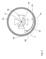
- the fan 16 has a direction of rotation 40.
- the fuel inlet 23 and the ignition means 26 are based on the combustion chamber axis A on radials R1, R2, which are at an angle [alpha] to each other.
- the angle [alpha] is between 5 ° and 180 °, preferably between 30 ° and 120 °. The angle is matched to the speed of the fan and the injection direction of the fuel inlet 23. In the illustrated embodiment, the angle [alpha] is 80 °.
- the ignition means 26 lies in the direction of rotation 40 behind the fuel inlet 23rd
Landscapes
- Engineering & Computer Science (AREA)
- Chemical & Material Sciences (AREA)
- Combustion & Propulsion (AREA)
- Mechanical Engineering (AREA)
- Portable Nailing Machines And Staplers (AREA)
Abstract
Description
Die vorliegende Erfindung betrifft ein brennkraftbetriebenes Setzgerät, der im Oberbegriff von Patentanspruch 1 genannten Art.The present invention relates to a combustion-powered setting tool, the type mentioned in the preamble of claim 1.
Derartige Setzgeräte können z. B. mit gasförmigen oder verdampfbaren flüssigen Brennstoffen betrieben werden. Bei einem Setzvorgang wird dann ein Setzkolben über expandierende Verbrennungsgase angetrieben, um ein Befestigungselement in ein Werkstück einzutreiben. Vor einem Verbrennungsvorgang wird der Brennstoff in den Brennraum eingespritzt und über einen im Brennraum befindlichen Ventilator bzw. Lüfter mit der sich im Brennraum befindlichen Luft vermischt. Dabei wird gleichzeitig die für die Verbrennung notwendige Turbulenz erzeugt. Nach dem Verbrennungsvorgang spült der Ventilator die Verbrennungsprodukte aus dem Brennraum und saugt Frischluft an. Zur Kühlung des Gerätes wird der Ventilator nach dem Spülen weiterbetrieben und nach einer definierten Zeitspanne abgeschaltet. Der Ventilator ist dabei über einen Motor, vorzugsweise einen Elektromotor angetrieben. Das Zünden des in der Brennkammer befindlichen Luft-Brennstoffgemisches erfolgt über eine Zündeinrichtung, die z. B. eine Zündkerze beinhaltet.Such setting devices can, for. B. be operated with gaseous or vaporizable liquid fuels. In a setting process, a setting piston is then driven by expanding combustion gases to drive a fastener into a workpiece. Before a combustion process, the fuel is injected into the combustion chamber and mixed with the air located in the combustion chamber via a fan or fan located in the combustion chamber. At the same time, the turbulence necessary for combustion is generated. After the combustion process, the fan flushes the combustion products from the combustion chamber and sucks in fresh air. To cool the device, the fan continues to operate after flushing and is switched off after a defined period of time. The fan is driven by a motor, preferably an electric motor. The ignition of the air-fuel mixture located in the combustion chamber via an ignition device, the z. B. includes a spark plug.
Aus der
Von Nachteil bei dieser Lösung ist, dass eine Zündung des Luft-Brennstoffgemischs erst möglich ist, wenn sich der in die Brennkammer eingespritzte Brennstoff weitgehend gleichmässig turbulent verteilt hat. Der Anwender darf den Triggerschalter, der die Zündung auslöst, daher nur zeitverzögert nach dem Einspritzen des Brennstoffs in die Brennkammer (wobei der Einspritzvorgang üblicherweise durch die Anpressbewegung des Setzgerätes an ein Werkstück initiiert wird) betätigen, um eine zuverlässige Zündung zu gewährleisten. Diese notwendige Verzögerungszeit kann vom Anwender als störend wahrgenommen werden. Wird das Einspritzen des Brennstoffs über eine Anpressbewegung des Setzgeräts an ein Werkstück ausgelöst, dann würde ein Vorspannen und Betätigen des Triggerschalters während oder unmittelbar nach einer Anpressbewegung zu Zündstörungen führen.A disadvantage of this solution is that ignition of the air-fuel mixture is only possible when the fuel injected into the combustion chamber has largely uniformly distributed turbulent. The user must therefore operate the trigger switch, which triggers the ignition, only after the injection of the fuel into the combustion chamber (the injection process is usually initiated by the pressing movement of the setting tool on a workpiece), in order to ensure a reliable ignition. This necessary delay time can be perceived as disturbing by the user. If the injection of the fuel triggered by a pressing movement of the setting device to a workpiece, then a biasing and pressing the trigger switch during or immediately after a pressing movement lead to ignition problems.
Die Aufgabe der vorliegenden Erfindung liegt darin, ein brennkraftbetriebenes Setzgerät der vorgenannten Art bereitzustellen, bei dem bereits nach minimaler Verzögerungszeit zwischen dem Einspritzen des Brennstoffs in die Brennkammer bzw. dem Anpressen des Setzgeräts an ein Werkstück und dem Auslösen eines Setzvorgangs über den Triggerschalter, das Setzen eines Befestigungselements störungsfrei und mit ausreichender Eintreibenergie möglich ist.The object of the present invention is to provide a combustion-driven setting tool of the aforementioned type, in which already after a minimum delay time between the injection of the fuel into the combustion chamber and the pressing of the setting device to a workpiece and the triggering of a setting operation on the trigger switch, the setting a fastener trouble-free and with sufficient driving energy is possible.
Diese Aufgabe wird durch ein brennkraftbetriebenes Setzgerät nach Anspruch 1 gelöst. Demnach sind sowohl der Brennstoffeinlass als auch das Zündmittel an dem ersten Ende der Brennkammer angeordnet, welches dem zweiten Ende mit dem Ventilator gegenüberliegt. Hierdurch liegt nun sowohl der Brennstoffeinlass als auch das Zündmittel in Strömungsrichtung der vom Ventilator erzeugten Strömung, wodurch überraschenderweise bereits kurz nach dem Einspritzen des Brennstoffs erfolgreich gezündet werden kann, ohne dass es zu einem Ausblasen der Zündflamme kommt. Wie Tests gezeigt haben, bilden sich an der Phasengrenze der im Zweiphasengemisch aus Luft und Brennstoff befindlichen Brennstofftröpfchen lokal zündfähige Mischungsverhältnisse aus. Diese Konzentration an nicht vollständig verdampften Brennstofftröpfchen im Bereich des Zündmittels wird vorteilhaft ausgenutzt, um nach sehr kurzen Verzögerungszeiten und trotz nicht optimaler Vermischung von Luft und Brennstoff sicher zünden zu können und dieses ohne feststellbare Leistungsminderung.This object is achieved by a combustion-powered setting tool according to claim 1. Accordingly, both the fuel inlet and the ignition means are arranged at the first end of the combustion chamber, which is opposite to the second end with the fan. As a result, both the fuel inlet and the ignition means now lie in the direction of flow of the flow generated by the fan, which surprisingly can be ignited successfully shortly after the injection of the fuel, without the ignition flame being blown out. As tests have shown, locally ignitable mixing ratios develop at the phase boundary of the fuel droplets in the two-phase mixture of air and fuel. This concentration of incompletely evaporated fuel droplets in the area of the ignition means is advantageously utilized in order to be able to reliably ignite after very short delay times and despite not optimal mixing of air and fuel, and this without detectable power reduction.
Vorteilhaft liegen der Brennstoffeinlass und das Zündmittel bezogen auf die Brennkammerachse auf Radialen, die in einem Winkel zueinander liegen, der zwischen 5° und 180°, vorzugsweise zwischen 30° und 120°, beträgt. Hierdurch kann auch bei Vorliegen eines gewissen axialen Abstandes vom Brennstoffeinlass zum Zündmittel eine zumindest partielle Benetzung des Zündmittels mit Brennstofftröpfchen erzielt werden, die ein gut zündfähiges Luft-Brennstoffgemisch in unmittelbarer Umgebung des Zündmittels und damit eine gute Zündbarkeit des Luft-Brennstoffgemischs insgesamt bewirkt, auch wenn die Verdampfung des Brennstoffs und die Vermischung mit der Luft in der Brennkammer insgesamt noch nicht optimal ist.Advantageously, the fuel inlet and the ignition means are based on the combustion chamber axis on radials which are at an angle to each other, which is between 5 ° and 180 °, preferably between 30 ° and 120 °. In this way, even with the presence of a certain axial distance from the fuel inlet to the ignition means at least partial wetting of the ignition means can be achieved with fuel droplets, which is a good ignitable air-fuel mixture in the immediate vicinity of the ignition means and thus a good ignitability of the air-fuel mixture in total causes, even if the evaporation of the fuel and the mixing with the air in the combustion chamber is not yet optimal.
Von Vorteil ist ferner, dass der Ventilator in einer Drehrichtung betreibbar ist und dass das Zündmittel in Drehrichtung hinter dem Brennstoffeinlass liegt, wodurch die Zündbarkeit des Luft-Brennstoffgemischs noch weiter verbessert werden kann.A further advantage is that the fan is operable in one direction of rotation and that the ignition in the direction of rotation is behind the fuel inlet, whereby the ignitability of the air-fuel mixture can be further improved.
In den Zeichnungen ist die Erfindung in einem Ausführungsbeispiel dargestellt.In the drawings, the invention is shown in one embodiment.
- Fig. 1Fig. 1
- ein erfindungsgemässes brennkraftbetriebenes Setzgerät in teilweisem Längsschnitt,an inventive combustion-powered setting tool in partial longitudinal section,
- Fig. 2Fig. 2
-
ein Schnitt durch das Setzgerät gemäss der Linie II - II aus
Fig. 1 .a section through the setting tool according to the line II - IIFig. 1 ,
In den
Zum Antrieb gehören u. a. eine Brennkammer 15 und ein Führungszylinder 13, in dem ein Setzkolben 14 axial versetzbar angeordnet ist. Die Brennkammer 15, die eine Brennkammerachse A definiert, wird in dem in
Ein in der Brennkammer 15 im Bereich ihres zweiten axialen Endes 32 angeordneter und über einen Motor 17 antreibbarer Ventilator 16 dient sowohl der Erzeugung eines turbulenten Strömungsregimes eines in der geschlossenen Brennkammer 15 befindlichen Luft-Brennstoffgemisches als auch dem Ausspülen der geöffneten Brennkammer 15 mit Frischluft nach erfolgtem Setzvorgang. Der Motor 17 ist dabei an der Brennkammerrückwand 30 gelagert, die als Verschluss für die axial verschiebbare Brennkammerhülse 28 fungiert.A
Wie aus
An dem Setzgerät 10 ist ferner ein Anpressschalter 24 angeordnet, der ein Schaltsignal generiert, wenn das Setzgerät 10 mit seiner Mündung 27 an ein Werkstück angepresst wird (in den Figuren nicht dargestellt).On the
Das Setzgerät 10 kann mit einem Brenngas oder mit einem verdampfbaren Flüssigbrennstoff betrieben werden, das in einem Brennstoffreservoir 20, wie z. B. einer Brennstoffdose, bereitgestellt wird. Das Brennstoffreservoir 20 ist dabei über eine Brennstoffleitung 22 mit einem Brennstoffeinlass 23 in der Brennkammer 15 verbunden. Der Brennstoffeinlass 23 ist am ersten Ende 31 der Brennkammer 15 angeordnet und liegt damit, wie auch das Zündmittel 26, in Strömungsrichtung S der durch den Ventilator 16 erzeugbaren Strömung.The
In die Brennstoffleitung 22 ist eine Dosiereinrichtung 21, wie z. B. ein Dosierventil, zwischengeschaltet, die z. B. dann aktiviert wird, wenn der Anpressschalter 24 ein Anpresssignal übermittelt.In the
Wie aus
Zur Versorgung der elektrischen Verbraucher, wie z. B. der Zündeinrichtung und des Motors 17 mit elektrischer Energie ist weiterhin eine in den Figuren nicht dargestellte elektrische Energiequelle, wie z. B. ein Akkumulator, vorhanden.To supply the electrical consumers, such. As the ignition device and the
Claims (3)
mit einem in einem Führungszylinder (13) versetzbar geführten Setzkolben (14),
mit einer eine Brennkammerachse (A) definierenden Brennkammer (15), die ein dem Führungszylinder (13) benachbartes erstes Ende (31) und ein vom Führungszylinder (13) beabstandetes zweites Ende (32) aufweist,
mit einem in die Brennkammer (15) einmündenden Brennstoffeinlass (23) zum Einbringen von Brennstoff in die Brennkammer (15),
mit einem Zündmittel (26) zum Zünden von Brennstoff in der Brennkammer (15),
und mit einem über einen Motor (17) betreibbaren Ventilator (16), der an einer Rückwand (30) am zweiten Ende (32) der Brennkammer (15) gelagert ist,
dadurch gekennzeichnet,
dass sowohl der Brennstoffeinlass (23) als auch das Zündmittel (26) an dem ersten Ende (31) der Brennkammer (15) angeordnet sind.Internal combustion setting device (10) for driving in fastening elements,
with a setting piston (14) displaceably guided in a guide cylinder (13),
a combustion chamber (15) defining a combustion chamber axis (A) and having a first end (31) adjacent the guide cylinder (13) and a second end (32) spaced from the guide cylinder (13),
with a fuel inlet (23) opening into the combustion chamber (15) for introducing fuel into the combustion chamber (15),
with ignition means (26) for igniting fuel in the combustion chamber (15),
and a fan (16) which can be operated via a motor (17) and is mounted on a rear wall (30) at the second end (32) of the combustion chamber (15),
characterized,
in that both the fuel inlet (23) and the ignition means (26) are arranged at the first end (31) of the combustion chamber (15).
Priority Applications (1)
| Application Number | Priority Date | Filing Date | Title |
|---|---|---|---|
| PL09100019T PL2085189T3 (en) | 2008-01-29 | 2009-01-07 | Combustion type fastener driving device |
Applications Claiming Priority (1)
| Application Number | Priority Date | Filing Date | Title |
|---|---|---|---|
| DE102008000167A DE102008000167A1 (en) | 2008-01-29 | 2008-01-29 | Internal combustion setting device |
Publications (3)
| Publication Number | Publication Date |
|---|---|
| EP2085189A2 true EP2085189A2 (en) | 2009-08-05 |
| EP2085189A3 EP2085189A3 (en) | 2010-06-23 |
| EP2085189B1 EP2085189B1 (en) | 2011-06-08 |
Family
ID=40627172
Family Applications (1)
| Application Number | Title | Priority Date | Filing Date |
|---|---|---|---|
| EP09100019A Not-in-force EP2085189B1 (en) | 2008-01-29 | 2009-01-07 | Combustion type fastener driving device |
Country Status (8)
| Country | Link |
|---|---|
| US (1) | US9676089B2 (en) |
| EP (1) | EP2085189B1 (en) |
| JP (1) | JP5466856B2 (en) |
| CN (1) | CN101497187B (en) |
| AT (1) | ATE511956T1 (en) |
| DE (1) | DE102008000167A1 (en) |
| ES (1) | ES2364021T3 (en) |
| PL (1) | PL2085189T3 (en) |
Families Citing this family (1)
| Publication number | Priority date | Publication date | Assignee | Title |
|---|---|---|---|---|
| EP3524390B1 (en) * | 2018-01-19 | 2022-03-30 | Max Co., Ltd. | Driving tool |
Citations (1)
| Publication number | Priority date | Publication date | Assignee | Title |
|---|---|---|---|---|
| EP1693158A2 (en) | 2005-02-18 | 2006-08-23 | Hitachi Koki Co., Ltd. | Combustion-type power tool having ignition proof arrangement |
Family Cites Families (19)
| Publication number | Priority date | Publication date | Assignee | Title |
|---|---|---|---|---|
| IN157475B (en) * | 1981-01-22 | 1986-04-05 | Signode Corp | |
| US4773581A (en) * | 1986-06-13 | 1988-09-27 | Hitachi Koki Company, Ltd. | Combustion gas powered tool |
| US4721240A (en) * | 1986-07-02 | 1988-01-26 | Senco Products, Inc. | Cam-controlled self-contained internal combustion fastener driving tool |
| US4712379A (en) * | 1987-01-08 | 1987-12-15 | Pow-R Tools Corporation | Manual recycler for detonating impact tool |
| EP0424941B1 (en) * | 1989-10-27 | 1994-01-05 | Hitachi Koki Co., Ltd. | Combustion gas powered fastener driving tool |
| US5199626A (en) * | 1990-10-05 | 1993-04-06 | Hitachi Koki Company Limited | Combustion gas powered tool |
| US5752643A (en) * | 1995-05-23 | 1998-05-19 | Applied Tool Development Corporation | Internal combustion powered tool |
| US6123241A (en) * | 1995-05-23 | 2000-09-26 | Applied Tool Development Corporation | Internal combustion powered tool |
| US5680980A (en) * | 1995-11-27 | 1997-10-28 | Illinois Tool Works Inc. | Fuel injection system for combustion-powered tool |
| US6260519B1 (en) * | 1997-12-31 | 2001-07-17 | Porter-Cable Corporation | Internal combustion fastener driving tool accelerator plate |
| DE19950352C2 (en) * | 1999-10-19 | 2002-03-07 | Hilti Ag | Portable, combustion powered tool and method for driving its piston |
| FR2832344B1 (en) * | 2001-11-21 | 2004-01-23 | Spit Soc Prospect Inv Techn | COMPRESSED GAS PISTON FIXING APPARATUS |
| CN1273270C (en) * | 2002-08-09 | 2006-09-06 | 日立工机株式会社 | Nailing gun using gas as power |
| US6755159B1 (en) * | 2003-01-20 | 2004-06-29 | Illinois Tool Works Inc. | Valve mechanisms for elongated combustion chambers |
| US6863045B2 (en) * | 2003-05-23 | 2005-03-08 | Illinois Tool Works Inc. | Combustion apparatus having improved airflow |
| JP4147403B2 (en) * | 2003-07-31 | 2008-09-10 | マックス株式会社 | Combustion chamber structure of gas-fired impact tool |
| JP4395841B2 (en) * | 2004-09-29 | 2010-01-13 | 日立工機株式会社 | Combustion type driving tool |
| CN101218069B (en) * | 2005-06-29 | 2011-05-25 | 多系统私人有限公司 | A hand-held power tool |
| DE102006000179A1 (en) * | 2006-04-13 | 2007-10-18 | Hilti Ag | Internal combustion setting device |
-
2008
- 2008-01-29 DE DE102008000167A patent/DE102008000167A1/en not_active Withdrawn
-
2009
- 2009-01-07 PL PL09100019T patent/PL2085189T3/en unknown
- 2009-01-07 AT AT09100019T patent/ATE511956T1/en active
- 2009-01-07 ES ES09100019T patent/ES2364021T3/en active Active
- 2009-01-07 EP EP09100019A patent/EP2085189B1/en not_active Not-in-force
- 2009-01-15 US US12/321,339 patent/US9676089B2/en not_active Expired - Fee Related
- 2009-01-23 CN CN2009100097186A patent/CN101497187B/en not_active Expired - Fee Related
- 2009-01-26 JP JP2009014424A patent/JP5466856B2/en not_active Expired - Fee Related
Patent Citations (1)
| Publication number | Priority date | Publication date | Assignee | Title |
|---|---|---|---|---|
| EP1693158A2 (en) | 2005-02-18 | 2006-08-23 | Hitachi Koki Co., Ltd. | Combustion-type power tool having ignition proof arrangement |
Also Published As
| Publication number | Publication date |
|---|---|
| EP2085189B1 (en) | 2011-06-08 |
| JP5466856B2 (en) | 2014-04-09 |
| DE102008000167A1 (en) | 2009-07-30 |
| ES2364021T3 (en) | 2011-08-23 |
| US9676089B2 (en) | 2017-06-13 |
| CN101497187A (en) | 2009-08-05 |
| CN101497187B (en) | 2012-12-12 |
| ATE511956T1 (en) | 2011-06-15 |
| PL2085189T3 (en) | 2011-11-30 |
| EP2085189A3 (en) | 2010-06-23 |
| US20090188962A1 (en) | 2009-07-30 |
| JP2009178840A (en) | 2009-08-13 |
Similar Documents
| Publication | Publication Date | Title |
|---|---|---|
| DE10232035B4 (en) | Internal combustion-powered setting tool | |
| DE804504C (en) | Burner with ignition device for gas turbine combustion chambers | |
| EP2319036B1 (en) | Apparatus and method for producing explosions | |
| DE102005000200B4 (en) | Internal combustion setting device | |
| EP1782925B1 (en) | Combustion-driven fastener setting tool | |
| DE602005005791T2 (en) | LOGIC AND MODE DISPLAY FOR TOOL WITH REPEATABLE CYCLE FOR FUEL-POWERED TOOL FOR DRIVING FASTENER ELEMENTS | |
| EP1844904B1 (en) | Combustion-driven fastener setting tool | |
| EP1922568B1 (en) | Method and device for generating compression waves | |
| EP2106883A1 (en) | Fuel driven fastener | |
| DE3709976A1 (en) | METHOD AND SPARK PLUG FOR THE IGNITION OF VERY LOW FUEL-AIR MIXTURES, ESPECIALLY FOR GAS ENGINES | |
| DE102006000127B4 (en) | Internal combustion setting device | |
| EP2090404A2 (en) | Combustion type fastener driving device | |
| DE10260704A1 (en) | Combustion-powered setting tool | |
| DE10308359B4 (en) | Internal combustion-powered setting tool | |
| DE10259567A1 (en) | Combustion-powered setting tool | |
| EP2085189B1 (en) | Combustion type fastener driving device | |
| WO2015144687A1 (en) | Pyrotechnic driving device | |
| DE3139880A1 (en) | IGNITION DEVICE | |
| DE3207179A1 (en) | PISTON PISTON ENGINE | |
| DE102012103891A1 (en) | Detonation pulse coal gasification system | |
| DE102016224579A1 (en) | Injector for direct or indirect injection of a gaseous medium into a combustion chamber | |
| WO2011137543A1 (en) | Seal and method for producing a flashover barrier | |
| DE301715C (en) | ||
| DE10357842B4 (en) | Internal combustion setting device | |
| DE725178C (en) | Gas turbine |
Legal Events
| Date | Code | Title | Description |
|---|---|---|---|
| PUAI | Public reference made under article 153(3) epc to a published international application that has entered the european phase |
Free format text: ORIGINAL CODE: 0009012 |
|
| AK | Designated contracting states |
Kind code of ref document: A2 Designated state(s): AT BE BG CH CY CZ DE DK EE ES FI FR GB GR HR HU IE IS IT LI LT LU LV MC MK MT NL NO PL PT RO SE SI SK TR |
|
| AX | Request for extension of the european patent |
Extension state: AL BA RS |
|
| PUAL | Search report despatched |
Free format text: ORIGINAL CODE: 0009013 |
|
| AK | Designated contracting states |
Kind code of ref document: A3 Designated state(s): AT BE BG CH CY CZ DE DK EE ES FI FR GB GR HR HU IE IS IT LI LT LU LV MC MK MT NL NO PL PT RO SE SI SK TR |
|
| AX | Request for extension of the european patent |
Extension state: AL BA RS |
|
| GRAP | Despatch of communication of intention to grant a patent |
Free format text: ORIGINAL CODE: EPIDOSNIGR1 |
|
| 17P | Request for examination filed |
Effective date: 20101223 |
|
| AKX | Designation fees paid |
Designated state(s): AT BE BG CH CY CZ DE DK EE ES FI FR GB GR HR HU IE IS IT LI LT LU LV MC MK MT NL NO PL PT RO SE SI SK TR |
|
| RIC1 | Information provided on ipc code assigned before grant |
Ipc: B25C 1/08 20060101AFI20110126BHEP |
|
| GRAS | Grant fee paid |
Free format text: ORIGINAL CODE: EPIDOSNIGR3 |
|
| GRAA | (expected) grant |
Free format text: ORIGINAL CODE: 0009210 |
|
| AK | Designated contracting states |
Kind code of ref document: B1 Designated state(s): AT BE BG CH CY CZ DE DK EE ES FI FR GB GR HR HU IE IS IT LI LT LU LV MC MK MT NL NO PL PT RO SE SI SK TR |
|
| REG | Reference to a national code |
Ref country code: GB Ref legal event code: FG4D Free format text: NOT ENGLISH |
|
| REG | Reference to a national code |
Ref country code: CH Ref legal event code: EP |
|
| REG | Reference to a national code |
Ref country code: IE Ref legal event code: FG4D Free format text: LANGUAGE OF EP DOCUMENT: GERMAN |
|
| REG | Reference to a national code |
Ref country code: DE Ref legal event code: R096 Ref document number: 502009000725 Country of ref document: DE Effective date: 20110721 |
|
| REG | Reference to a national code |
Ref country code: ES Ref legal event code: FG2A Ref document number: 2364021 Country of ref document: ES Kind code of ref document: T3 Effective date: 20110823 |
|
| REG | Reference to a national code |
Ref country code: SE Ref legal event code: TRGR |
|
| REG | Reference to a national code |
Ref country code: NL Ref legal event code: VDEP Effective date: 20110608 |
|
| PG25 | Lapsed in a contracting state [announced via postgrant information from national office to epo] |
Ref country code: HR Free format text: LAPSE BECAUSE OF FAILURE TO SUBMIT A TRANSLATION OF THE DESCRIPTION OR TO PAY THE FEE WITHIN THE PRESCRIBED TIME-LIMIT Effective date: 20110608 Ref country code: LT Free format text: LAPSE BECAUSE OF FAILURE TO SUBMIT A TRANSLATION OF THE DESCRIPTION OR TO PAY THE FEE WITHIN THE PRESCRIBED TIME-LIMIT Effective date: 20110608 Ref country code: NO Free format text: LAPSE BECAUSE OF FAILURE TO SUBMIT A TRANSLATION OF THE DESCRIPTION OR TO PAY THE FEE WITHIN THE PRESCRIBED TIME-LIMIT Effective date: 20110908 |
|
| PG25 | Lapsed in a contracting state [announced via postgrant information from national office to epo] |
Ref country code: SI Free format text: LAPSE BECAUSE OF FAILURE TO SUBMIT A TRANSLATION OF THE DESCRIPTION OR TO PAY THE FEE WITHIN THE PRESCRIBED TIME-LIMIT Effective date: 20110608 Ref country code: FI Free format text: LAPSE BECAUSE OF FAILURE TO SUBMIT A TRANSLATION OF THE DESCRIPTION OR TO PAY THE FEE WITHIN THE PRESCRIBED TIME-LIMIT Effective date: 20110608 Ref country code: LV Free format text: LAPSE BECAUSE OF FAILURE TO SUBMIT A TRANSLATION OF THE DESCRIPTION OR TO PAY THE FEE WITHIN THE PRESCRIBED TIME-LIMIT Effective date: 20110608 Ref country code: GR Free format text: LAPSE BECAUSE OF FAILURE TO SUBMIT A TRANSLATION OF THE DESCRIPTION OR TO PAY THE FEE WITHIN THE PRESCRIBED TIME-LIMIT Effective date: 20110909 Ref country code: CY Free format text: LAPSE BECAUSE OF FAILURE TO SUBMIT A TRANSLATION OF THE DESCRIPTION OR TO PAY THE FEE WITHIN THE PRESCRIBED TIME-LIMIT Effective date: 20110608 |
|
| REG | Reference to a national code |
Ref country code: PL Ref legal event code: T3 |
|
| PG25 | Lapsed in a contracting state [announced via postgrant information from national office to epo] |
Ref country code: NL Free format text: LAPSE BECAUSE OF FAILURE TO SUBMIT A TRANSLATION OF THE DESCRIPTION OR TO PAY THE FEE WITHIN THE PRESCRIBED TIME-LIMIT Effective date: 20110608 |
|
| REG | Reference to a national code |
Ref country code: IE Ref legal event code: FD4D |
|
| PG25 | Lapsed in a contracting state [announced via postgrant information from national office to epo] |
Ref country code: IS Free format text: LAPSE BECAUSE OF FAILURE TO SUBMIT A TRANSLATION OF THE DESCRIPTION OR TO PAY THE FEE WITHIN THE PRESCRIBED TIME-LIMIT Effective date: 20111008 Ref country code: IE Free format text: LAPSE BECAUSE OF FAILURE TO SUBMIT A TRANSLATION OF THE DESCRIPTION OR TO PAY THE FEE WITHIN THE PRESCRIBED TIME-LIMIT Effective date: 20110608 Ref country code: PT Free format text: LAPSE BECAUSE OF FAILURE TO SUBMIT A TRANSLATION OF THE DESCRIPTION OR TO PAY THE FEE WITHIN THE PRESCRIBED TIME-LIMIT Effective date: 20111010 Ref country code: CZ Free format text: LAPSE BECAUSE OF FAILURE TO SUBMIT A TRANSLATION OF THE DESCRIPTION OR TO PAY THE FEE WITHIN THE PRESCRIBED TIME-LIMIT Effective date: 20110608 Ref country code: EE Free format text: LAPSE BECAUSE OF FAILURE TO SUBMIT A TRANSLATION OF THE DESCRIPTION OR TO PAY THE FEE WITHIN THE PRESCRIBED TIME-LIMIT Effective date: 20110608 |
|
| PG25 | Lapsed in a contracting state [announced via postgrant information from national office to epo] |
Ref country code: SK Free format text: LAPSE BECAUSE OF FAILURE TO SUBMIT A TRANSLATION OF THE DESCRIPTION OR TO PAY THE FEE WITHIN THE PRESCRIBED TIME-LIMIT Effective date: 20110608 Ref country code: RO Free format text: LAPSE BECAUSE OF FAILURE TO SUBMIT A TRANSLATION OF THE DESCRIPTION OR TO PAY THE FEE WITHIN THE PRESCRIBED TIME-LIMIT Effective date: 20110608 |
|
| PLBE | No opposition filed within time limit |
Free format text: ORIGINAL CODE: 0009261 |
|
| STAA | Information on the status of an ep patent application or granted ep patent |
Free format text: STATUS: NO OPPOSITION FILED WITHIN TIME LIMIT |
|
| 26N | No opposition filed |
Effective date: 20120309 |
|
| PG25 | Lapsed in a contracting state [announced via postgrant information from national office to epo] |
Ref country code: DK Free format text: LAPSE BECAUSE OF FAILURE TO SUBMIT A TRANSLATION OF THE DESCRIPTION OR TO PAY THE FEE WITHIN THE PRESCRIBED TIME-LIMIT Effective date: 20110608 |
|
| REG | Reference to a national code |
Ref country code: DE Ref legal event code: R097 Ref document number: 502009000725 Country of ref document: DE Effective date: 20120309 |
|
| BERE | Be: lapsed |
Owner name: HILTI AKTIENGESELLSCHAFT Effective date: 20120131 |
|
| PG25 | Lapsed in a contracting state [announced via postgrant information from national office to epo] |
Ref country code: MC Free format text: LAPSE BECAUSE OF NON-PAYMENT OF DUE FEES Effective date: 20120131 |
|
| PG25 | Lapsed in a contracting state [announced via postgrant information from national office to epo] |
Ref country code: BE Free format text: LAPSE BECAUSE OF NON-PAYMENT OF DUE FEES Effective date: 20120131 |
|
| PG25 | Lapsed in a contracting state [announced via postgrant information from national office to epo] |
Ref country code: MK Free format text: LAPSE BECAUSE OF FAILURE TO SUBMIT A TRANSLATION OF THE DESCRIPTION OR TO PAY THE FEE WITHIN THE PRESCRIBED TIME-LIMIT Effective date: 20110608 |
|
| PG25 | Lapsed in a contracting state [announced via postgrant information from national office to epo] |
Ref country code: BG Free format text: LAPSE BECAUSE OF FAILURE TO SUBMIT A TRANSLATION OF THE DESCRIPTION OR TO PAY THE FEE WITHIN THE PRESCRIBED TIME-LIMIT Effective date: 20110908 |
|
| PG25 | Lapsed in a contracting state [announced via postgrant information from national office to epo] |
Ref country code: MT Free format text: LAPSE BECAUSE OF FAILURE TO SUBMIT A TRANSLATION OF THE DESCRIPTION OR TO PAY THE FEE WITHIN THE PRESCRIBED TIME-LIMIT Effective date: 20110608 |
|
| REG | Reference to a national code |
Ref country code: CH Ref legal event code: PL |
|
| PG25 | Lapsed in a contracting state [announced via postgrant information from national office to epo] |
Ref country code: LI Free format text: LAPSE BECAUSE OF NON-PAYMENT OF DUE FEES Effective date: 20130131 Ref country code: CH Free format text: LAPSE BECAUSE OF NON-PAYMENT OF DUE FEES Effective date: 20130131 |
|
| PGFP | Annual fee paid to national office [announced via postgrant information from national office to epo] |
Ref country code: ES Payment date: 20131211 Year of fee payment: 6 Ref country code: PL Payment date: 20131212 Year of fee payment: 6 |
|
| PG25 | Lapsed in a contracting state [announced via postgrant information from national office to epo] |
Ref country code: TR Free format text: LAPSE BECAUSE OF FAILURE TO SUBMIT A TRANSLATION OF THE DESCRIPTION OR TO PAY THE FEE WITHIN THE PRESCRIBED TIME-LIMIT Effective date: 20110608 |
|
| PG25 | Lapsed in a contracting state [announced via postgrant information from national office to epo] |
Ref country code: LU Free format text: LAPSE BECAUSE OF NON-PAYMENT OF DUE FEES Effective date: 20120107 |
|
| PGFP | Annual fee paid to national office [announced via postgrant information from national office to epo] |
Ref country code: IT Payment date: 20140110 Year of fee payment: 6 |
|
| PG25 | Lapsed in a contracting state [announced via postgrant information from national office to epo] |
Ref country code: HU Free format text: LAPSE BECAUSE OF FAILURE TO SUBMIT A TRANSLATION OF THE DESCRIPTION OR TO PAY THE FEE WITHIN THE PRESCRIBED TIME-LIMIT Effective date: 20090107 |
|
| REG | Reference to a national code |
Ref country code: AT Ref legal event code: MM01 Ref document number: 511956 Country of ref document: AT Kind code of ref document: T Effective date: 20140107 |
|
| PG25 | Lapsed in a contracting state [announced via postgrant information from national office to epo] |
Ref country code: AT Free format text: LAPSE BECAUSE OF NON-PAYMENT OF DUE FEES Effective date: 20140107 |
|
| REG | Reference to a national code |
Ref country code: FR Ref legal event code: PLFP Year of fee payment: 8 |
|
| PG25 | Lapsed in a contracting state [announced via postgrant information from national office to epo] |
Ref country code: IT Free format text: LAPSE BECAUSE OF NON-PAYMENT OF DUE FEES Effective date: 20150107 |
|
| REG | Reference to a national code |
Ref country code: ES Ref legal event code: FD2A Effective date: 20160226 |
|
| PG25 | Lapsed in a contracting state [announced via postgrant information from national office to epo] |
Ref country code: ES Free format text: LAPSE BECAUSE OF NON-PAYMENT OF DUE FEES Effective date: 20150108 |
|
| PG25 | Lapsed in a contracting state [announced via postgrant information from national office to epo] |
Ref country code: PL Free format text: LAPSE BECAUSE OF NON-PAYMENT OF DUE FEES Effective date: 20150107 |
|
| REG | Reference to a national code |
Ref country code: FR Ref legal event code: PLFP Year of fee payment: 9 |
|
| REG | Reference to a national code |
Ref country code: FR Ref legal event code: PLFP Year of fee payment: 10 |
|
| PGFP | Annual fee paid to national office [announced via postgrant information from national office to epo] |
Ref country code: DE Payment date: 20200121 Year of fee payment: 12 Ref country code: SE Payment date: 20200121 Year of fee payment: 12 Ref country code: GB Payment date: 20200123 Year of fee payment: 12 |
|
| PGFP | Annual fee paid to national office [announced via postgrant information from national office to epo] |
Ref country code: FR Payment date: 20200121 Year of fee payment: 12 |
|
| REG | Reference to a national code |
Ref country code: DE Ref legal event code: R119 Ref document number: 502009000725 Country of ref document: DE |
|
| REG | Reference to a national code |
Ref country code: SE Ref legal event code: EUG |
|
| GBPC | Gb: european patent ceased through non-payment of renewal fee |
Effective date: 20210107 |
|
| PG25 | Lapsed in a contracting state [announced via postgrant information from national office to epo] |
Ref country code: FR Free format text: LAPSE BECAUSE OF NON-PAYMENT OF DUE FEES Effective date: 20210131 |
|
| PG25 | Lapsed in a contracting state [announced via postgrant information from national office to epo] |
Ref country code: SE Free format text: LAPSE BECAUSE OF NON-PAYMENT OF DUE FEES Effective date: 20210108 Ref country code: GB Free format text: LAPSE BECAUSE OF NON-PAYMENT OF DUE FEES Effective date: 20210107 Ref country code: DE Free format text: LAPSE BECAUSE OF NON-PAYMENT OF DUE FEES Effective date: 20210803 |