EP2085158A1 - Mandrel mill, its operating method, and seamless pipe manufacturing method - Google Patents
Mandrel mill, its operating method, and seamless pipe manufacturing method Download PDFInfo
- Publication number
- EP2085158A1 EP2085158A1 EP07830466A EP07830466A EP2085158A1 EP 2085158 A1 EP2085158 A1 EP 2085158A1 EP 07830466 A EP07830466 A EP 07830466A EP 07830466 A EP07830466 A EP 07830466A EP 2085158 A1 EP2085158 A1 EP 2085158A1
- Authority
- EP
- European Patent Office
- Prior art keywords
- roll
- grooved
- stand
- groove bottom
- hollow shell
- Prior art date
- Legal status (The legal status is an assumption and is not a legal conclusion. Google has not performed a legal analysis and makes no representation as to the accuracy of the status listed.)
- Withdrawn
Links
Images


Classifications
-
- B—PERFORMING OPERATIONS; TRANSPORTING
- B21—MECHANICAL METAL-WORKING WITHOUT ESSENTIALLY REMOVING MATERIAL; PUNCHING METAL
- B21B—ROLLING OF METAL
- B21B17/00—Tube-rolling by rollers of which the axes are arranged essentially perpendicular to the axis of the work, e.g. "axial" tube-rolling
- B21B17/02—Tube-rolling by rollers of which the axes are arranged essentially perpendicular to the axis of the work, e.g. "axial" tube-rolling with mandrel, i.e. the mandrel rod contacts the rolled tube over the rod length
- B21B17/04—Tube-rolling by rollers of which the axes are arranged essentially perpendicular to the axis of the work, e.g. "axial" tube-rolling with mandrel, i.e. the mandrel rod contacts the rolled tube over the rod length in a continuous process
-
- B—PERFORMING OPERATIONS; TRANSPORTING
- B21—MECHANICAL METAL-WORKING WITHOUT ESSENTIALLY REMOVING MATERIAL; PUNCHING METAL
- B21B—ROLLING OF METAL
- B21B27/00—Rolls, roll alloys or roll fabrication; Lubricating, cooling or heating rolls while in use
- B21B27/02—Shape or construction of rolls
- B21B27/03—Sleeved rolls
- B21B27/035—Rolls for bars, rods, rounds, tubes, wire or the like
-
- B—PERFORMING OPERATIONS; TRANSPORTING
- B21—MECHANICAL METAL-WORKING WITHOUT ESSENTIALLY REMOVING MATERIAL; PUNCHING METAL
- B21B—ROLLING OF METAL
- B21B2267/00—Roll parameters
- B21B2267/02—Roll dimensions
-
- B—PERFORMING OPERATIONS; TRANSPORTING
- B21—MECHANICAL METAL-WORKING WITHOUT ESSENTIALLY REMOVING MATERIAL; PUNCHING METAL
- B21B—ROLLING OF METAL
- B21B2267/00—Roll parameters
- B21B2267/02—Roll dimensions
- B21B2267/06—Roll diameter
Definitions
- the present invention relates to a mandrel mill that does not generate holes, roll slip flaws, cornice flaws, and the like, an operating method of the same, and a production method of a seamless pipe.
- a mandrel mill that has six to eight units of roll stands, each composed of a pair of upper and lower mill rolls, such that the groove bottom directions of the roll grooves of the anteroposterior stand across from one another at 90°.
- a hollow shell is continuously elongated by arranging the mandrel bar in a roll groove array formed by the plurality of roll stands.
- Fig. 3 is a schematic diagram showing an entire configuration of the mandrel mill.
- the mandrel mill has grooved-roll stands 11 to 14 each composed of a pair of mill rolls 4, and multiple units (four units in the figure) are provided consecutively so that each roll stand across from each other at 90°.
- a seamless pipe is produced by inserting a mandrel bar 3 in a hollow shell 2 bored in advance with a piercer, and sequentially rolling and elongating this by the roll stands 11 to 14.
- the roll stands provided are called, in the order from mill entry side, a first stand (11 in the figure), a second stand (12 in the figure), a third stand (13 in the figure), and a fourth stand (14 in the figure).
- the wall thickness is first reduced at the first stand.
- Patent document 1 discloses an invention of a mandrel mill that includes a plurality of consecutively provided grooved-roll stands crossing with each other and rolls a hollow shell with a mandrel bar provided in a roll groove array formed by the grooved-roll stands, wherein the ellipticity of the groove of a first or/and second stand is in the range of 1.25 to 1.40. This prevents a generation of hole occurrence and pipe end cracking.
- Patent document 2 discloses an invention of a mandrel mill that includes a plurality of grooved-roll stands and rolls a hollow shell with a mandrel bar provided in a roll groove array formed by the grooved-roll stands, wherein the circumferential length of the roll groove of a first stand is at least 1.12 times the hot-finished circumferential length of the pipe on the mill exit side.
- Patent document 3 discloses an invention of a mandrel mill that includes a plurality of grooved-roll stands and rolls a hollow shell with a mandrel bar provided in a roll groove array formed by the grooved-roll stands, wherein the radius of groove bottom curvature of the roll groove of a first stand is 0.54 times or less the roll groove bottom interval.
- Patent document 4 discloses an invention of a mandrel mill that includes a plurality of consecutively provided grooved-roll stands and elongates a hollow shell continuously with a mandrel bar provided in a roll groove array formed by the grooved-roll stands.
- the radius R1 of the groove bottom curvature of the roll groove of each stand and a displacement-offset-amount S between the groove bottom curvature center and the mill center have a ratio S/R1 of at least 30, and the ellipticity of a second stand is 1.20 or less.
- Patent document 1 describes that in order to prevent a hole generation on the elongated seamless pipe, it is effective to limit the ellipticity of the groove. However, even though the ellipticity is adjusted, a flaw may occur in some cases on the elongated seamless pipe depending on the offset amount.
- Patent document 2 discloses a technique that limits the circumferential length of the roll groove of the first stand, or further the second stand of the mandrel mill, within a certain range relative to a hot-finished circumferential length of the pipe at the mill exit side, a suitable gap is secured between the mandrel bar and the inner surface of the hollow shell that is being elongated, thereby preventing missed stripping.
- ellipticity nor offset, which could cause a flaw to occur on the elongated seamless pipe.
- Patent document 3 describes that hole occurrence is suppressed. However, even if the offset is reduced, if the ellipticity is not adjusted in an appropriate range, a flaw may occur on the elongated seamless pipe.
- Patent document 4 describes that in the mandrel mill, by limiting the ellipticity and offset as well within predetermined ranges, it is possible to suppress a generation of the necking phenomenon and reduce the hole occurrence. However, there is no indication of the relationship between the ellipticity and the offset.
- the present inventors conducted an extensive study to solve the problems of the conventional art, and as a result, have found an effective ellipticity-offset balance for preventing flaw generation on an elongated seamless pipe, resulting in a completion of the present invention. It is an objective of the present invention to provide a mandrel mill with minimized flaw occurrence on an elongated seamless pipe.
- the gist of the present invention is: a mandrel mill indicated as (1) below; an operating method of the mandrel mill indicated as (2) below; and a production method of a seamless pipe indicated as (3) below.
- a mandrel mill comprising a plurality of consecutively provided grooved-roll stands and a mandrel bar provided in a roll groove array formed by the grooved-roll stands so as to continuously elongate a hollow shell, characterized in that roll grooves of at least a first stand and a second stand are arranged so as to satisfy conditions represented by the following formulas (1) to (4).
- a is a ratio of S/R1 between a groove bottom curvature radius R1 of each grooved-roll and a displacement-offset-amount S between a groove bottom curvature center and a mill center
- b is ellipticity
- An operating method of a mandrel mill including a plurality of consecutively provided grooved-roll stands and a mandrel bar provided in a roll groove array formed by the grooved-roll stands, characterized in that a hollow shell is continuously elongated when a groove bottom curvature radius R1, a displacement-offset-amount S, and ellipticity of each of grooved-rolls satisfy conditions represented by the above formulas (1) to (4) in at least a first stand and a second stand, whereby a hole occurrence and flaw generation are prevented.
- a production method of a seamless pipe using a mandrel mill including a plurality of consecutively provided grooved-roll stands and a mandrel bar provided in a roll groove array formed by the grooved-roll stands, characterized in that a hollow shell is continuously elongated when a groove bottom curvature radius R1, a displacement-offset-amount S, and ellipticity of each of grooved-rolls satisfy conditions represented by the above formulas (1) to (4) in at least a first stand and a second stand.
- a hollow shell is rolled with a good balance between offset and ellipticity, thereby making it possible to suppress the hole occurrence and flaw generation on an elongated seamless pipe. Therefore, flaws such as necking can be suppressed even in the case of rolling a thin wall pipe and a high alloy steel pipe, which are easily subject to defects.
- the mandrel mill of the present invention is a mandrel mill that includes a plurality of consecutively provided grooved-roll stands and also a mandrel bar provided in a roll groove array formed by the grooved-roll stands so as to continuously elongate a hollow shell.
- multiple units (four units in the figure) of grooved-roll stands 1 each composed of a pair of mill rolls 4 are provided so as to cross each other at 90°.
- a seamless pipe is produced by inserting a mandrel bar 3 in a hollow shell 2 bored in advance with a piercer, and sequentially elongating this on the roll stands 11 to 14.
- Fig. 4 is a schematic diagram showing a rolling state of a hollow shell in the mandrel mill.
- (a) to (f) each shows a rolling state of the hollow shell at first to the sixth stands.
- (b) to (f) each shows a figure with the grooved-rolls omitted.
- Fig. 4 an example of a mandrel mill with six stands is shown, but the number of the stands is not limited.
- the rolling is conducted by continuously passing a hollow shell 2 that a mandrel bar 3 is inserted through the pairs of grooved-rolls 4.
- the wall thickness and diameter reduce gradually through the stands.
- a hollow shell 2 is elongated by the grooved-rolls 4 and the mandrel bar 3. Specifically, a part of the hollow shell 2 located at a groove bottom portion of each grooved-roll 4 (a portion of contact between each grooved-roll 4 and the hollow shell 2) is rolled to reduce the wall thickness. On the other hand, a part of the hollow shell 2 located at a flange part (a portion where each grooved-roll 4 and the hollow shell 2 do not make contact) is pulled and elongated in the hollow shell axis direction based on the deformation of the part of the hollow shell 2 located at the groove bottom portion in the hollow shell axis direction that results from rolling.
- the part of the hollow shell 2 located at the flange part receives no internal surface pressure and substantially no external surface pressure, and thus close to uniaxial tension, receiving only tensile force in the hollow shell axis direction. Therefore, the part of the hollow shell 2 located at the flange part easily encounters what is called a necking phenomenon, which refers to a partial reduction in wall thickness. If this necking phenomenon occurs dramatically, a hollow shell that is being elongated will break into generate holes.
- the roll grooves of at least the first stand and the second stand are arranged so as to satisfy the following formulas (1) to (4).
- a is a ratio of S/R1 between a groove bottom curvature radius R1 of each grooved-roll and a displacement-offset-amount S between a groove bottom curvature center and a mill center
- "b” is ellipticity.
- the groove bottom curvature radius R1 of each grooved-roll and the displacement-offset-amount S between the groove bottom curvature center and the mill center are shown in Fig. 1 .
- the ellipticity is represented by C/(R1-S) using the curvature radius R1, the displacement-offset-amount S between the groove bottom curvature center and a mill center O, and a longer radius C of the hollow shell are shown in Fig. 1 .
- Fig. 2 is a figure showing the relationship between: the ratio S/R1 between the groove bottom curvature radius R1 of the grooved-roll and the displacement-offset-amount S between the groove bottom curvature center and the mill center, and the ellipticity in the mandrel mill of the present invention. It is noted that the relationship shown in the figure is regarding the first stand.
- the hollow shell that is being elongated turns into an under-filled state relative to the grooved-roll.
- the term "under-filled” means such a state that the outer circumferential length of the hollow shell being elongated does not increase sufficiently and thus is excessively small relative to the groove circumferential length (outer circumferential length of a projected groove profile). In the under-filled state, drawing-out failure of the bar (striping failure) or hole occurrence due to necking arises even though the ellipticity is large.
- the hollow shell that is being elongated turns into an over-filled state relative to the grooved-roll.
- the term "over-filled” means such a state that the outer circumferential length of the hollow shell being elongated increases excessively, resulting in protrusion from the grooved flange. In the over-filled state, the hollow shell protrudes from the grooved flange and a burning flaw occurs on the surface of the hollow shell.
- the grooved-rolls of only at least the first stand and the second stand may be arranged so as to satisfy the conditions represented by the foregoing formulas (1) to (4). This is because the rolling reduction rate in the first stand and the second stand is generally larger than that in the other stands during mandrel mill rolling, and the influence that the groove shapes of the first and second stands have on rolling is significantly larger than the influence of the groove shapes of the third and later stands.
- the hollow shell is rolled with a good balance between offset and ellipticity, and thus it is possible to suppress hole occurrence and flaw generation in an elongated seamless pipe. Therefore, a flaw such as necking can be suppressed even in the case of rolling a thin wall pipe and a high alloy steel pipe, which are easily subject to flaws.
Landscapes
- Engineering & Computer Science (AREA)
- Mechanical Engineering (AREA)
- Physics & Mathematics (AREA)
- Geometry (AREA)
- Reduction Rolling/Reduction Stand/Operation Of Reduction Machine (AREA)
Abstract



Description
- The present invention relates to a mandrel mill that does not generate holes, roll slip flaws, cornice flaws, and the like, an operating method of the same, and a production method of a seamless pipe.
- Ordinarily, as a rolling machine of seamless pipes, there is a mandrel mill that has six to eight units of roll stands, each composed of a pair of upper and lower mill rolls, such that the groove bottom directions of the roll grooves of the anteroposterior stand across from one another at 90°. In the mandrel mill, a hollow shell is continuously elongated by arranging the mandrel bar in a roll groove array formed by the plurality of roll stands.
-
Fig. 3 is a schematic diagram showing an entire configuration of the mandrel mill. As shown in the figure, the mandrel mill has grooved-roll stands 11 to 14 each composed of a pair ofmill rolls 4, and multiple units (four units in the figure) are provided consecutively so that each roll stand across from each other at 90°. A seamless pipe is produced by inserting amandrel bar 3 in ahollow shell 2 bored in advance with a piercer, and sequentially rolling and elongating this by the roll stands 11 to 14. The roll stands provided are called, in the order from mill entry side, a first stand (11 in the figure), a second stand (12 in the figure), a third stand (13 in the figure), and a fourth stand (14 in the figure). Generally, the wall thickness is first reduced at the first stand. -
Patent document 1 discloses an invention of a mandrel mill that includes a plurality of consecutively provided grooved-roll stands crossing with each other and rolls a hollow shell with a mandrel bar provided in a roll groove array formed by the grooved-roll stands, wherein the ellipticity of the groove of a first or/and second stand is in the range of 1.25 to 1.40. This prevents a generation of hole occurrence and pipe end cracking. -
Patent document 2 discloses an invention of a mandrel mill that includes a plurality of grooved-roll stands and rolls a hollow shell with a mandrel bar provided in a roll groove array formed by the grooved-roll stands, wherein the circumferential length of the roll groove of a first stand is at least 1.12 times the hot-finished circumferential length of the pipe on the mill exit side. -
Patent document 3 discloses an invention of a mandrel mill that includes a plurality of grooved-roll stands and rolls a hollow shell with a mandrel bar provided in a roll groove array formed by the grooved-roll stands, wherein the radius of groove bottom curvature of the roll groove of a first stand is 0.54 times or less the roll groove bottom interval. -
Patent document 4 discloses an invention of a mandrel mill that includes a plurality of consecutively provided grooved-roll stands and elongates a hollow shell continuously with a mandrel bar provided in a roll groove array formed by the grooved-roll stands. In the mandrel mill, the radius R1 of the groove bottom curvature of the roll groove of each stand and a displacement-offset-amount S between the groove bottom curvature center and the mill center have a ratio S/R1 of at least 30, and the ellipticity of a second stand is 1.20 or less. -
- [Patent document 1] Japanese Unexamined Patent Publication No.
2001-113306 - [Patent document 2] Japanese Patent Publication No.
2582705 - [Patent document 3] Japanese Examined Patent Publication
Hei 7-102369 - [Patent document 4] Japanese Patent Publication No.
2985719 -
Patent document 1 describes that in order to prevent a hole generation on the elongated seamless pipe, it is effective to limit the ellipticity of the groove. However, even though the ellipticity is adjusted, a flaw may occur in some cases on the elongated seamless pipe depending on the offset amount. -
Patent document 2 discloses a technique that limits the circumferential length of the roll groove of the first stand, or further the second stand of the mandrel mill, within a certain range relative to a hot-finished circumferential length of the pipe at the mill exit side, a suitable gap is secured between the mandrel bar and the inner surface of the hollow shell that is being elongated, thereby preventing missed stripping. However, in some cases no consideration is given to ellipticity nor offset, which could cause a flaw to occur on the elongated seamless pipe. -
Patent document 3 describes that hole occurrence is suppressed. However, even if the offset is reduced, if the ellipticity is not adjusted in an appropriate range, a flaw may occur on the elongated seamless pipe. -
Patent document 4 describes that in the mandrel mill, by limiting the ellipticity and offset as well within predetermined ranges, it is possible to suppress a generation of the necking phenomenon and reduce the hole occurrence. However, there is no indication of the relationship between the ellipticity and the offset. - The present inventors conducted an extensive study to solve the problems of the conventional art, and as a result, have found an effective ellipticity-offset balance for preventing flaw generation on an elongated seamless pipe, resulting in a completion of the present invention. It is an objective of the present invention to provide a mandrel mill with minimized flaw occurrence on an elongated seamless pipe.
- The gist of the present invention is: a mandrel mill indicated as (1) below; an operating method of the mandrel mill indicated as (2) below; and a production method of a seamless pipe indicated as (3) below.
- (1) A mandrel mill comprising a plurality of consecutively provided grooved-roll stands and a mandrel bar provided in a roll groove array formed by the grooved-roll stands so as to continuously elongate a hollow shell, characterized in that roll grooves of at least a first stand and a second stand are arranged so as to satisfy conditions represented by the following formulas (1) to (4).
-


- In the formulas above, "a" is a ratio of S/R1 between a groove bottom curvature radius R1 of each grooved-roll and a displacement-offset-amount S between a groove bottom curvature center and a mill center, and "b" is ellipticity.
- (2) An operating method of a mandrel mill including a plurality of consecutively provided grooved-roll stands and a mandrel bar provided in a roll groove array formed by the grooved-roll stands, characterized in that a hollow shell is continuously elongated when a groove bottom curvature radius R1, a displacement-offset-amount S, and ellipticity of each of grooved-rolls satisfy conditions represented by the above formulas (1) to (4) in at least a first stand and a second stand, whereby a hole occurrence and flaw generation are prevented.
- (3) A production method of a seamless pipe using a mandrel mill including a plurality of consecutively provided grooved-roll stands and a mandrel bar provided in a roll groove array formed by the grooved-roll stands, characterized in that a hollow shell is continuously elongated when a groove bottom curvature radius R1, a displacement-offset-amount S, and ellipticity of each of grooved-rolls satisfy conditions represented by the above formulas (1) to (4) in at least a first stand and a second stand.
- According to the present invention, a hollow shell is rolled with a good balance between offset and ellipticity, thereby making it possible to suppress the hole occurrence and flaw generation on an elongated seamless pipe. Therefore, flaws such as necking can be suppressed even in the case of rolling a thin wall pipe and a high alloy steel pipe, which are easily subject to defects.
- The mandrel mill of the present invention is a mandrel mill that includes a plurality of consecutively provided grooved-roll stands and also a mandrel bar provided in a roll groove array formed by the grooved-roll stands so as to continuously elongate a hollow shell.
- Referring to
Fig. 3 shown above, in the mandrel mill of the present invention, multiple units (four units in the figure) of grooved-roll stands 1 each composed of a pair ofmill rolls 4 are provided so as to cross each other at 90°. A seamless pipe is produced by inserting amandrel bar 3 in ahollow shell 2 bored in advance with a piercer, and sequentially elongating this on the roll stands 11 to 14. -
Fig. 4 is a schematic diagram showing a rolling state of a hollow shell in the mandrel mill. InFig. 4, (a) to (f) each shows a rolling state of the hollow shell at first to the sixth stands. Additionally, (b) to (f) each shows a figure with the grooved-rolls omitted. InFig. 4 , an example of a mandrel mill with six stands is shown, but the number of the stands is not limited. - Referring to
Fig. 4 , in the mandrel mill of the present invention, the rolling is conducted by continuously passing ahollow shell 2 that amandrel bar 3 is inserted through the pairs of grooved-rolls 4. The wall thickness and diameter reduce gradually through the stands. - Referring to
Fig. 3 , in the mandrel mill, ahollow shell 2 is elongated by the grooved-rolls 4 and themandrel bar 3. Specifically, a part of thehollow shell 2 located at a groove bottom portion of each grooved-roll 4 (a portion of contact between each grooved-roll 4 and the hollow shell 2) is rolled to reduce the wall thickness. On the other hand, a part of thehollow shell 2 located at a flange part (a portion where each grooved-roll 4 and thehollow shell 2 do not make contact) is pulled and elongated in the hollow shell axis direction based on the deformation of the part of thehollow shell 2 located at the groove bottom portion in the hollow shell axis direction that results from rolling. - That is, the part of the
hollow shell 2 located at the flange part receives no internal surface pressure and substantially no external surface pressure, and thus close to uniaxial tension, receiving only tensile force in the hollow shell axis direction. Therefore, the part of thehollow shell 2 located at the flange part easily encounters what is called a necking phenomenon, which refers to a partial reduction in wall thickness. If this necking phenomenon occurs dramatically, a hollow shell that is being elongated will break into generate holes. - In the mandrel mill of the present invention, in order to eliminate such a problem, the roll grooves of at least the first stand and the second stand are arranged so as to satisfy the following formulas (1) to (4).
-


- In the formulas above, "a" is a ratio of S/R1 between a groove bottom curvature radius R1 of each grooved-roll and a displacement-offset-amount S between a groove bottom curvature center and a mill center, and "b" is ellipticity. The groove bottom curvature radius R1 of each grooved-roll and the displacement-offset-amount S between the groove bottom curvature center and the mill center are shown in
Fig. 1 . The ellipticity is represented by C/(R1-S) using the curvature radius R1, the displacement-offset-amount S between the groove bottom curvature center and a mill center O, and a longer radius C of the hollow shell are shown inFig. 1 . -
Fig. 2 is a figure showing the relationship between: the ratio S/R1 between the groove bottom curvature radius R1 of the grooved-roll and the displacement-offset-amount S between the groove bottom curvature center and the mill center, and the ellipticity in the mandrel mill of the present invention. It is noted that the relationship shown in the figure is regarding the first stand. - Referring to
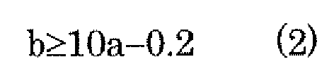
Fig. 2 , in the case where the foregoing formula (1) is not satisfied, that is, where the value of the ratio S/R1 is too small relative to ellipticity b, the hollow shell that is being elongated turns into an under-filled state relative to the grooved-roll. The term "under-filled" means such a state that the outer circumferential length of the hollow shell being elongated does not increase sufficiently and thus is excessively small relative to the groove circumferential length (outer circumferential length of a projected groove profile). In the under-filled state, drawing-out failure of the bar (striping failure) or hole occurrence due to necking arises even though the ellipticity is large. - In the case where the foregoing formula (2) is not satisfied, that is, where the value of the ratio S/R1 is too large relative to the ellipticity b, the hollow shell that is being elongated turns into an over-filled state relative to the grooved-roll. The term "over-filled" means such a state that the outer circumferential length of the hollow shell being elongated increases excessively, resulting in protrusion from the grooved flange. In the over-filled state, the hollow shell protrudes from the grooved flange and a burning flaw occurs on the surface of the hollow shell. In addition, such a phenomenon occurs that the advance speed of a part of the hollow shell corresponding to the roll groove bottom part of the next stand is smaller than the circumferential speed of the roll groove bottom part, resulting in a flaw in the form of a fold on the hollow shell.
- In the case where the foregoing formula (3) is not satisfied, that is, where the value of the ellipticity b is too large relative to the ratio S/R1, an over-filled state results as well. In this case, the hollow shell that is being elongated protrudes from the grooved flange to cause burning to occur, resulting in a burning flaw on the surface. In addition, such a phenomenon occurs that the advance speed of the hollow shell in the next stand is smaller than the circumferential speed of the roll groove bottom part, resulting in a flaw in the form of a fold on the hollow shell.
- In the case where the foregoing formula (4) is not satisfied, that is, where the value of the ellipticity b is too small relative to the ratio S/R1, an under-filled state results. In this case, problems occur including drawing-out failure of the bar (striping failure) or hole occurrence due to necking.
- In the mandrel mill of the present invention, the grooved-rolls of only at least the first stand and the second stand may be arranged so as to satisfy the conditions represented by the foregoing formulas (1) to (4). This is because the rolling reduction rate in the first stand and the second stand is generally larger than that in the other stands during mandrel mill rolling, and the influence that the groove shapes of the first and second stands have on rolling is significantly larger than the influence of the groove shapes of the third and later stands.
- As described above, specifying the ratio S/R1 and the ellipticity individually may fail to solve various problems associated with rolling. In the present invention, by operating the mandrel mill under the conditions represented by the foregoing formulas (1) to (4), it is possible to stably produce a seamless pipe without hole occurrence and flaws.
- According to the present invention, the hollow shell is rolled with a good balance between offset and ellipticity, and thus it is possible to suppress hole occurrence and flaw generation in an elongated seamless pipe. Therefore, a flaw such as necking can be suppressed even in the case of rolling a thin wall pipe and a high alloy steel pipe, which are easily subject to flaws.
-
-
Fig. 1 is a schematic diagram showing a positional relationship between a grooved-roll, a hollow shell, and a mandrel bar in a mandrel mill of the present invention. -
Fig. 2 is a figure showing a relationship between: the ratio S/R1 between a groove bottom curvature radius R1 of a grooved-roll and a displacement-offset-amount S between a groove bottom curvature center and the mill center, and ellipticity in the mandrel of the present invention. -
Fig. 3 is a schematic diagram showing an entire configuration of the mandrel mill. -
Fig. 4 is a schematic diagram showing a rolling state of a seamless pipe on the mandrel mill, with (a) to (f) respectively showing a rolling state of the seamless pipe at the first to sixth stands of the mandrel mill. -
- 11, 12, 13, 14. Roll stand
- 2. Hollow shell
- 3. Mandrel bar
- 4. Grooved-roll
- R1. Groove bottom curvature center
- O. Mill center
- S. Displacement-offset-amount between groove bottom curvature center and mill center
- C. Longer radius of pipe material
Claims (3)
- A mandrel mill comprising a plurality of consecutively provided grooved-roll stands and a mandrel bar provided in a roll groove array formed by the grooved-roll stands so as to continuously elongate a hollow shell, characterized in that roll grooves of at least a first stand and a second stand are arranged so as to satisfy conditions represented by the following formulas (1) to (4):


- An operating method of a mandrel mill including a plurality of consecutively provided grooved-roll stands and a mandrel bar provided in a roll groove array formed by the grooved-roll stands, characterized in that a hollow shell is continuously elongated when a groove bottom curvature radius R1, a displacement-offset-amount S, and ellipticity of each of grooved-rolls satisfy conditions represented by the following formulas (1) to (4) in at least a first stand and a second stand, whereby a hole occurrence and flaw generation are prevented:


- A production method of a seamless pipe using a mandrel mill including a plurality of consecutively provided grooved-roll stands and a mandrel bar provided in a roll groove array formed by the grooved-roll stands, characterized in that a hollow shell is continuously elongated when a groove bottom curvature radius R1, a displacement-offset-amount S, and ellipticity of each of grooved-rolls satisfy conditions represented by the following formulas (1) to (4) in at least a first stand and a second stand:



Applications Claiming Priority (2)
| Application Number | Priority Date | Filing Date | Title |
|---|---|---|---|
| JP2006303776A JP2008119706A (en) | 2006-11-09 | 2006-11-09 | Mandrel mill, method of operation thereof, and method of manufacturing seamless pipe |
| PCT/JP2007/070732 WO2008056540A1 (en) | 2006-11-09 | 2007-10-24 | Mandrel mill, its operating method, and seamless pipe manufacturing method |
Publications (2)
| Publication Number | Publication Date |
|---|---|
| EP2085158A1 true EP2085158A1 (en) | 2009-08-05 |
| EP2085158A4 EP2085158A4 (en) | 2012-08-01 |
Family
ID=39364363
Family Applications (1)
| Application Number | Title | Priority Date | Filing Date |
|---|---|---|---|
| EP07830466A Withdrawn EP2085158A4 (en) | 2006-11-09 | 2007-10-24 | CONTINUOUS ROLL, METHOD OF OPERATING SAME, AND METHOD FOR MANUFACTURING SEAMLESS PIPE |
Country Status (6)
| Country | Link |
|---|---|
| US (2) | US20100064753A1 (en) |
| EP (1) | EP2085158A4 (en) |
| JP (1) | JP2008119706A (en) |
| CN (1) | CN101534969A (en) |
| BR (1) | BRPI0718203A2 (en) |
| WO (1) | WO2008056540A1 (en) |
Families Citing this family (10)
| Publication number | Priority date | Publication date | Assignee | Title |
|---|---|---|---|---|
| DE102006031564A1 (en) * | 2006-07-07 | 2008-01-10 | Gesenkschmiede Schneider Gmbh | Method for producing a rotationally symmetrical part, in particular shaft |
| MX2012003886A (en) * | 2009-09-29 | 2012-04-20 | Sumitomo Metal Ind | Multi-roll mandrel mill and method for manufacturing seamless pipe. |
| WO2011088069A1 (en) * | 2010-01-12 | 2011-07-21 | Wadsworth Lewis W | Apparatus and method for cutting tubular members |
| MX336959B (en) * | 2010-07-07 | 2016-02-05 | Nippon Steel & Sumitomo Metal Corp | Mandrel mill and method for manufacturing seamless pipe. |
| CN102371362B (en) * | 2010-08-25 | 2013-08-28 | 中国有色(沈阳)冶金机械有限公司 | Static and dynamic balance processing method for heavy-duty hollow roller way |
| DE102010052084B3 (en) * | 2010-11-16 | 2012-02-16 | V&M Deutschland Gmbh | Process for the economic production of seamless hot-rolled tubes in continuous tube rolling mills |
| CN104785525B (en) * | 2015-04-07 | 2017-03-01 | 浙江嘉翔精密机械技术有限公司 | A kind of method improving nuclear steam generator performance of heat exchange tubes |
| DE102018207908A1 (en) * | 2018-05-18 | 2019-11-21 | Sms Group Gmbh | Stretch reduction mill with improved diameter and wall thickness tolerance |
| CN109909297B (en) * | 2019-02-28 | 2020-06-02 | 西安建筑科技大学 | Reverse-cone spiral roller superfine crystal rolling method for large-size high-temperature alloy bar |
| KR102322805B1 (en) * | 2020-01-23 | 2021-11-10 | 가천대학교 산학협력단 | Method for manufacturing multi-layered nuclear fuel cladding |
Family Cites Families (4)
| Publication number | Priority date | Publication date | Assignee | Title |
|---|---|---|---|---|
| JP2582705B2 (en) | 1991-06-21 | 1997-02-19 | 川崎製鉄株式会社 | Mandrel mill |
| JPH07102369B2 (en) | 1991-08-22 | 1995-11-08 | 川崎製鉄株式会社 | Mandrel mill |
| JP2985719B2 (en) * | 1995-04-04 | 1999-12-06 | 住友金属工業株式会社 | Mandrel mill |
| JP2001113306A (en) | 1999-10-18 | 2001-04-24 | Sumitomo Metal Ind Ltd | Method for producing high alloy seamless steel pipe and rolling die used for the method |
-
2006
- 2006-11-09 JP JP2006303776A patent/JP2008119706A/en active Pending
-
2007
- 2007-10-24 US US12/312,423 patent/US20100064753A1/en not_active Abandoned
- 2007-10-24 CN CNA2007800413905A patent/CN101534969A/en active Pending
- 2007-10-24 WO PCT/JP2007/070732 patent/WO2008056540A1/en not_active Ceased
- 2007-10-24 EP EP07830466A patent/EP2085158A4/en not_active Withdrawn
- 2007-10-24 BR BRPI0718203A patent/BRPI0718203A2/en not_active Application Discontinuation
-
2009
- 2009-09-21 US US12/563,229 patent/US20100132425A1/en not_active Abandoned
Non-Patent Citations (2)
| Title |
|---|
| No further relevant documents disclosed * |
| See also references of WO2008056540A1 * |
Also Published As
| Publication number | Publication date |
|---|---|
| US20100132425A1 (en) | 2010-06-03 |
| BRPI0718203A2 (en) | 2015-09-22 |
| US20100064753A1 (en) | 2010-03-18 |
| EP2085158A4 (en) | 2012-08-01 |
| WO2008056540A1 (en) | 2008-05-15 |
| CN101534969A (en) | 2009-09-16 |
| JP2008119706A (en) | 2008-05-29 |
Similar Documents
| Publication | Publication Date | Title |
|---|---|---|
| US20100132425A1 (en) | Mandrel mill, operating method of the same and production method of seamless pipe | |
| EP2241385A1 (en) | Process for manufacturing ultrathin wall metallic pipe by cold drawing method | |
| US7530248B2 (en) | Plug for use in piercing mill | |
| EP2484457A1 (en) | Multi-roll mandrel mill and method for manufacturing seamless pipe | |
| EP1679136B1 (en) | Method of manufacturing seamless tube by three-roll mandrel mill | |
| US8122749B2 (en) | Mandrel mill and process for manufacturing a seamless pipe | |
| EP2591865B1 (en) | Mandrel mill and method for manufacturing seamless pipe | |
| JP4888252B2 (en) | Seamless pipe cold rolling method | |
| EP2135689A1 (en) | Method for producing seamless pipe and hole type roll | |
| EP2156908A1 (en) | Mandrel mill and process for manufacturing seamless pipe | |
| JP4935550B2 (en) | Metal tube manufacturing method | |
| JP5655737B2 (en) | Seamless steel pipe manufacturing method | |
| EP1889669B1 (en) | Drawing rolling method by mandrel mill | |
| JP2014166649A (en) | Method for manufacturing seamless steel pipe | |
| JP2985719B2 (en) | Mandrel mill | |
| CA2076402C (en) | Mandrel mill for seamless steel tubes | |
| JP2001113306A (en) | Method for producing high alloy seamless steel pipe and rolling die used for the method | |
| JPH0857506A (en) | Mandrel mill | |
| JP4035960B2 (en) | Method of rolling a tube with a mandrel mill | |
| JP2010131602A (en) | Method of manufacturing seamless pipe | |
| JPH0569011A (en) | Skew rolling method for tube | |
| JPS6046805A (en) | Control method of mandrel mill | |
| JP2007229795A (en) | Barrel type piercer roll to reduce circumferential shear strain |
Legal Events
| Date | Code | Title | Description |
|---|---|---|---|
| PUAI | Public reference made under article 153(3) epc to a published international application that has entered the european phase |
Free format text: ORIGINAL CODE: 0009012 |
|
| 17P | Request for examination filed |
Effective date: 20090609 |
|
| AK | Designated contracting states |
Kind code of ref document: A1 Designated state(s): AT BE BG CH CY CZ DE DK EE ES FI FR GB GR HU IE IS IT LI LT LU LV MC MT NL PL PT RO SE SI SK TR |
|
| DAX | Request for extension of the european patent (deleted) | ||
| A4 | Supplementary search report drawn up and despatched |
Effective date: 20120704 |
|
| RIC1 | Information provided on ipc code assigned before grant |
Ipc: B21B 27/02 20060101ALI20120628BHEP Ipc: B21B 17/02 20060101AFI20120628BHEP |
|
| RAP1 | Party data changed (applicant data changed or rights of an application transferred) |
Owner name: NIPPON STEEL & SUMITOMO METAL CORPORATION |
|
| STAA | Information on the status of an ep patent application or granted ep patent |
Free format text: STATUS: THE APPLICATION IS DEEMED TO BE WITHDRAWN |
|
| 18D | Application deemed to be withdrawn |
Effective date: 20130205 |