EP2084933B1 - A method for transmitting control channel in a mobile communication system - Google Patents
A method for transmitting control channel in a mobile communication system Download PDFInfo
- Publication number
- EP2084933B1 EP2084933B1 EP08712324A EP08712324A EP2084933B1 EP 2084933 B1 EP2084933 B1 EP 2084933B1 EP 08712324 A EP08712324 A EP 08712324A EP 08712324 A EP08712324 A EP 08712324A EP 2084933 B1 EP2084933 B1 EP 2084933B1
- Authority
- EP
- European Patent Office
- Prior art keywords
- channel
- transmitted
- dpcch
- channel signal
- transmission
- Prior art date
- Legal status (The legal status is an assumption and is not a legal conclusion. Google has not performed a legal analysis and makes no representation as to the accuracy of the status listed.)
- Active
Links
Images


Classifications
-
- H—ELECTRICITY
- H04—ELECTRIC COMMUNICATION TECHNIQUE
- H04W—WIRELESS COMMUNICATION NETWORKS
- H04W72/00—Local resource management
- H04W72/12—Wireless traffic scheduling
-
- H—ELECTRICITY
- H04—ELECTRIC COMMUNICATION TECHNIQUE
- H04W—WIRELESS COMMUNICATION NETWORKS
- H04W72/00—Local resource management
- H04W72/50—Allocation or scheduling criteria for wireless resources
- H04W72/535—Allocation or scheduling criteria for wireless resources based on resource usage policies
-
- H—ELECTRICITY
- H04—ELECTRIC COMMUNICATION TECHNIQUE
- H04B—TRANSMISSION
- H04B7/00—Radio transmission systems, i.e. using radiation field
- H04B7/24—Radio transmission systems, i.e. using radiation field for communication between two or more posts
- H04B7/26—Radio transmission systems, i.e. using radiation field for communication between two or more posts at least one of which is mobile
- H04B7/2603—Arrangements for wireless physical layer control
-
- H—ELECTRICITY
- H04—ELECTRIC COMMUNICATION TECHNIQUE
- H04W—WIRELESS COMMUNICATION NETWORKS
- H04W76/00—Connection management
- H04W76/20—Manipulation of established connections
Definitions
- the present invention relates to a mobile communication system, and more particularly to methods and apparatuses for transmitting a control channel in a mobile communication system.
- uplink transmission that is, in a case where a user equipment functions as a transmitter, various methods for controlling power such that the capacity of a battery is increased or power consumption of the user equipment is decreased so as to increase the duration of the user equipment have been suggested.
- the methods for controlling the power may include a discontinuous transmission scheme.
- the discontinuous transmission scheme may be, for example, a method for instantaneously reducing a data transmission output or setting a silent state when a voice signal is not transmitted in a mobile phone or a portable wireless phone.
- a talk time of each of the two persons is equal to or less than a half of a total talk time.
- a transmission time may be reduced to 50% or less. Accordingly, advantages including conservation of battery power, reduction of a load of a transmitter amplifier, and channel sharing with another signal in view of time division multiplexing (TDM) can be obtained.
- TDM time division multiplexing
- the present invention is directed to methods
- the present invention it is possible to increase efficiency of a mobile communication system.
- transmission error occurs and a portion of one transmission unit cannot be transmitted, the remaining signal is transmitted.
- the occurred error is corrected and detected by an error correcting and detecting method applied to the channel so as to increase a probability of transmission/reception success, thereby increasing the effectiveness.
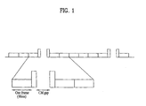
- FIG. 1 shows a schematic frame structure according to the compressed mode transmission scheme.
- the compressed mode transmission scheme any one frame or two continuous frames is used as a compressed frame including a compressed mode (CM) gap in a frame or between two continuous frames.
- CM compressed mode
- some slots of a frame which is determined to be used as the compressed frame, that is, slots included in the CM gap, are not used in data transmission. These slots are used to perform an operation for interrupting data transmission/reception in the CM gap and searching for a neighboring cell and a neighboring network.
- data can be transmitted in a state of increasing transmission power with respect to some slots of the compressed frame.
- slots for transmitting data with the increased transmission power are preferably located before the CM gap is started and after the CM gap is finished.
- the amount of power increased in the some slots of the compressed frame may be determined according to the reduction of a transmission time. Examples of a factor for measuring communication quality may include a bit error rate (BER) and a frame error rate (FER).
- BER bit error rate
- FER frame error rate
- the compressed frame may be periodically generated in the compressed mode and may be generated by a request if necessary.
- the rate and the type of the compressed frame may be determined by requirements due to various channel environments and measurements.
- an uplink discontinuous transmission (DTX) scheme will be described as another method for controlling power.
- DTX uplink discontinuous transmission
- a discontinuous transmission operation is designed in uplink transmission. That is, the user equipment discontinuously transmits data.
- a method for differently controlling power according to an interval in which the data is transmitted and an interval in which the data is not transmitted, that is, the DTX interval is used.
- the data is not always transmitted. Accordingly, when the data is transmitted, the user equipment is in a use state or an "ON" state and, when the data is not transmitted, the user equipment is in a state of minimizing power consumption, such as a "sleep" state or an "OFF" state.
- the uplink discontinuous transmission scheme and the compressed mode transmission scheme are simultaneously operated, an accurate operation of the user equipment is preferably examined.
- the operation of the user equipment according to embodiments of the present invention when the uplink compressed mode transmission scheme and the uplink discontinuous transmission scheme are simultaneously applied will be described in detail.
- E-DCH enhanced-dedicated channel
- FIG. 2 is a drawing for illustrating a discontinuous transmission operation of the E-DCH.
- the E-DCH is a channel for transmitting uplink packet data and is mapped to a physical channel such as an enhanced dedicated physical data channel (E-DPDCH) and an enhanced dedicated physical control channel (E-DPCCH).
- E-DPDCH is the physical channel which is used to transmit E-DCH data
- E-DPCCH is the physical channel which is used to transmit control information associated with the E-DCH.
- the E-DPDCH and the E-DPCCH are simultaneously transmitted.
- a dedicated physical control channel (DPCCH) is also transmitted. More particularly, the control information generated in a first layer is transmitted through DPCCH. For example, at least one of feedback information (FBI), a transmit power control (TPC) command and transport-format combination indicator (TFCI) including an uplink pilot for supporting the channel estimation can be transmitted.
- FBI feedback information
- TPC transmit power control
- TFCI transport-format combination indicator
- control information which is not transmitted through the DPCCH that is, the control information which is characteristic in the E-DCH
- the E-DPCCH can be transmitted through the E-DPCCH as the control information used in the E-DCH demodulation.
- the TFCI, HARQ information and scheduling request information can be transmitted through the E-DPCCH.
- the E-DPDCH, the E-DPCCH and the DPCCH can be simultaneously transmitted and are multiplexed using different codes or different orthogonal phase components.
- the user equipment starts DPCCH transmission before transmitting the E-DPDCH and the E-DPCCH.
- the E-DPDCH and E-DPCCH transmission is started at a predetermined time after the DPCCH transmission is started or after a predetermined number of slots are transmitted.
- the DPCCH signal which is transmitted before the E-DPDCH and the E-DPCCH are transmitted is called a DPCCH preamble.
- FIG. 3 shows a case where two slots are used as the DPCCH preamble.
- the number of slots used as the DPCCH preamble is denoted by N.
- the user equipment transmits the DPCCH at a predetermined time after the E-DPDCH and E-DPCCH transmission is finished or after a predetermined number of slots are transmitted, and then completes the E-DCH transmission process.
- the DPCCH signal which is transmitted after the E-DPDCH and E-DPCCH transmission is finished is called a DPCCH postamble.
- FIG. 2 shows a case where one slot is used as the DPCCH postamble.
- the number of slots used as the DPCCH postamble is denoted by M.
- the DPCCH preamble and the DPCCH postamble are respectively transmitted before and after the E-DPDCH and the E-DPCCH are transmitted such that the reception side, for example, the node-B detects the E-DCH with higher probability of success.
- the number of slots used as the DPCCH preamble may be determined according to the data transmitting state of the user equipment. For example, if the user does not transmit the data during a time longer than a predetermined time interval before transmitting the E-DCH, more slots can be used as the DPCCH preamble, compared with a case where the user does not transmit the data during the predetermined time interval or less.
- the number N1 of slots used as the DPCCH preamble may be 2.
- the number N2 of slots used as the DPCCH preamble may be 15. This is because, if the data is not transmitted during a longer time, it is preferable that control information necessary for uplink synchronization should be transmitted and more control information required for performing power control should be transmitted.
- the DPCCH preamble is transmitted by a predetermined number N of slots, for example, two slots, before transmitting the E-DPDCH and the E-DPCCH
- the DPCCH postamble is transmitted by a predetermined number M of slots, for example, one slot, after transmitting the E-DPDCH and the E-DPCCH.
- a process of transmitting the DPCCH preamble, transmitting the E-DPDCH and the E-DPCCH, and transmitting the DPCCH postamble is considered to one transmission unit.
- One transmission unit shown at the left side of FIG. 2 is referred to as a first transmission unit and one transmission unit shown at the right of FIG. 2 is referred to as a second transmission unit.
- a predetermined DTX interval may be set between the first transmission unit and the second transmission unit.
- the data is not transmitted in the DTX interval. If the DTX interval is finished, the DPCCH preamble is transmitted again, the E-DCH, that is, the E-DPDCH and the E-DPCCH, is transmitted, and the DPCCH postamble is transmitted, thereby finishing the data transmission of one transmission unit.
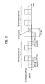
- FIG. 3 is a drawing for illustrating the operation of the user equipment according to an embodiment of the present invention when the compressed mode transmission scheme and the discontinuous transmission scheme are simultaneously applied in E-DCH transmission.
- the E-DPDCH and the E-DPCCH are transmitted and the DPCCH is transmitted together with the E-DPDCH and the E-DPCCH.
- the DTX interval according to the discontinuous transmission scheme exists between the first transmission unit which is first transmitted and the second transmission unit which is next transmitted.
- the transmission of the data corresponding to the first transmission unit is finished and, after the DTX interval, the transmission of the data corresponding to the second transmission unit is started by transmitting the DPCCH preamble.
- the DPCCH preamble of the second transmission unit is determined to be transmitted in the CM gap according to the compressed mode transmission scheme, the DPCCH preamble is not transmitted in a portion or all slots overlapping the CM gap, but the E-DPDCH and the E-DPCCH as well as the remaining DPCCH preamble, the DPCCH signal and the DPCCH postamble are transmitted, according to the embodiment of the present invention.
- the DPCCH postamble is determined to be transmitted in the CM gap according to the compressed mode transmission scheme, the DPCCH postamble is not transmitted in a portion or all of the slots overlapping the CM gap, but the E-DPDCH and the E-DPCCH as well as the DPCCH preamble, the DPCCH signal and the remaining DPCCH postamble are transmitted.
- ECS error check sum
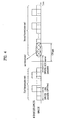
- FIG. 4 is a drawing for illustrating the operation of the user equipment according to another embodiment of the present invention when the compressed mode transmission scheme and the discontinuous transmission scheme are simultaneously applied in E-DCH transmission.
- the number N2 of slots used as the DPCCH preamble may be set to 15. This is because, as described, if the data is not transmitted during the longer time, it is preferable that the control information necessary for uplink synchronization should be transmitted and more control information required for performing power control should be transmitted.
- the long-length DPCCH preamble is not transmitted in a portion or all of slots overlapping the CM gap, but the E-DPDCH and the E-DPCCH as well as the remaining DPCCH preamble, the DPCCH signal and the DPCCH postamble are transmitted, according to the embodiment of the present invention.
- the DPCCH postamble is determined to be transmitted in the CM gap according to the compressed mode transmission scheme, the DPCCH postamble is not transmitted in a portion or all of the slots overlapping the CM gap, but the E-DPDCH and the E-DPCCH as well as the DPCCH preamble, the DPCCH signal and the remaining DPCCH postamble are transmitted.
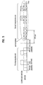
- FIG. 5 is a drawing for illustrating the operation of the user equipment according to an example of the present invention when the compressed mode transmission scheme and the discontinuous transmission scheme are simultaneously applied in E-DCH transmission.
- the DPCCH and the remaining channel signals of the overall transmission unit associated with the long-length DPCCH preamble as well as slots overlapping the CM gap are not transmitted according to the example of the present invention. That is, all of the remaining DPCCH preamble, the DPCCH signal, the DPCCH postamble, the E-DPDCH and the E-DPCCH are not transmitted.
- the DPCCH postamble is determined to be transmitted in the CM gap according to the compressed mode transmission scheme
- the DPCCH and the remaining channel signals of the overall transmission unit associated with the DPCCH preamble as well as slots overlapping the CM gap are not transmitted according to the example of the present invention. That is, all of the DPCCH preamble, the DPCCH signal, the remaining DPCCH postamble, the E-DPDCH and the E-DPCCH are not transmitted.
- the control information for uplink synchronization and the control information required for controlling the power are transmitted through the long-length DPCCH preamble transmitted after the data is not transmitted during the predetermined time interval. Accordingly, if the Long-length DPCCH preamble is not normally received, it is difficult to establish uplink synchronization. In this case, fatal error may occur in the data transmission/reception.
- HS-DPCCH high speed-dedicated physical control channel
- FIG. 6 is a drawing for illustrating a discontinuous transmission operation of the HS-DPCCH.
- the HS-DPCCH sends an uplink feedback signal associated with the transmission of a high speed-downlink shared channel (HS-DSCH).
- the feedback signal associated with the HS-DSCH includes a HARQ acknowledgement (ACK/NACK) and a channel quality indication.
- ACK/NACK HARQ acknowledgement
- the DPCCH is also transmitted. That is, the control information for controlling the power and the necessary control information including a pilot for performing the channel estimation can be transmitted through the DPCCH.
- the HS-DPCCH and the DPCCH may be simultaneously transmitted and are multiplexed using different codes or different orthogonal phase components.
- the user equipment starts the transmission of the DPCCH before transmitting the HS-DPCCH. That is, the transmission of the HS-DPCCH is started at a predetermined time after the transmission of the DPCCH is started or a predetermined number of slots are transmitted.
- the DPCCH signal which is transmitted before the HS-DPCCH is transmitted is called a DPCCH preamble.
- FIG. 6 shows a case where two slots are used as the DPCCH preamble.
- the number of slots used as the DPCCH preamble is denoted by N.
- the user equipment transmits the DPCCH at a predetermined time after the HS-DPCCH transmission is finished or after a predetermined number of slots are transmitted, and then completes the HS-DPCCH transmission process.
- the DPCCH signal which is transmitted after the HS-DPCCH transmission is finished is called a DPCCH postamble.
- FIG. 6 shows a case where one slot is used as the DPCCH postamble.
- M the number of slots used as the DPCCH postamble.
- the DPCCH preamble and the DPCCH postamble are respectively transmitted before and after the HS-DPCCH are transmitted such that the reception side, for example, the node-B detects the HS-DPCCH with higher probability of success.
- the DPCCH preamble is transmitted by the predetermined number N of slots, for example, two slots, before the HS-DPCCH transmission and the DPCCH postamble is transmitted by the predetermined number M of slots, for example, one slot, after the HS-DPCCH transmission.
- a process of transmitting the DPCCH preamble, transmitting the HS-DPCCH, and transmitting the DPCCH is considered as one transmission unit.
- One transmission unit shown at the left side of FIG. 6 is referred to as a first transmission unit and one transmission unit shown at the right of FIG. 6 is referred to as a second transmission unit.
- a predetermined DTX interval may be set between the first transmission unit and the second transmission unit and the data is not transmitted in the DTX interval. If the DTX interval is finished, the DPCCH preamble is transmitted again, the DPCCH and the HS-DPCCH are transmitted, and the DPCCH postamble is transmitted, thereby finishing the data transmission of one transmission unit.
- the HS-DPCCH is transmitted from a middle portion of a slot immediately next to the slot, in which the DPCCH preamble is transmitted, in the discontinuous transmission scheme of the HS-DPCCH as shown in FIG. 6 .
- the HS-DPCCH is transmitted until a middle portion of a slot immediately before a slot, in which the DPCCH postamble is transmitted, in the discontinuous transmission scheme of the HS-DPCCH as shown in FIG. 6 .
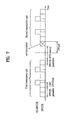
- FIG. 7 is a drawing for illustrating the operation of the user equipment according to an embodiment of the present invention when the compressed mode transmission scheme and the discontinuous transmission scheme are simultaneously applied in HS-DPCCH transmission.
- the HS-DPCCH is transmitted and the DPCCH is transmitted together with the HS-DPCCH.
- the DTX interval according to the discontinuous transmission scheme exists between the first transmission unit which is first transmitted and the second transmission unit which is next transmitted.
- the transmission of the data corresponding to the first transmission unit is finished and, after the DTX interval, the transmission of the data corresponding to the second transmission unit is started by transmitting the DPCCH preamble.
- the DPCCH preamble of the second transmission unit is determined to be transmitted in the CM gap according to the compressed mode transmission scheme, the DPCCH preamble is not transmitted in a portion or all of slots overlapping the CM gap, but the HS-DPCCH as well as the remaining DPCCH preamble, the DPCCH signal and the DPCCH postamble are transmitted, according to the embodiment of the present invention.
- the DPCCH postamble is determined to be transmitted in the CM gap according to the compressed mode transmission scheme, the DPCCH postamble is not transmitted in a portion or all of the slots overlapping the CM gap, but the HS-DPCCH as well as the DPCCH preamble, the DPCCH signal and the remaining DPCCH postamble are transmitted.
- FIG. 8 is a drawing for illustrating the operation of the user equipment according to an example of the present invention when the compressed mode transmission scheme and the discontinuous transmission scheme are simultaneously applied in HS-DPCCH transmission.
- the DPCCH and the remaining channel signals of the overall transmission unit associated with the DPCCH preamble as well as slots overlapping the CM gap are not transmitted according to the example of the present invention.
- the DPCCH postamble is determined to be transmitted in the CM gap according to the compressed mode transmission scheme
- the DPCCH and the remaining channel signals of the overall transmission unit associated with the DPCCH preamble as well as slots overlapping the CM gap are not transmitted according to the example of the present invention. That is, all of the DPCCH preamble, the DPPCCH signal, the remaining DPCCH postamble and the HS-DPCCH are not transmitted.
- the ECS for checking the error may not be applied to the HS-DPCCH data and the HARQ operation may not be performed. Accordingly, if at least one of the DPCCH preamble and the DPCCH postamble is transmitted in the CM gap and thus cannot be transmitted, a probability of deterioration in reception capability due to the lack of the DPCCH preamble and the DPCCH postamble at the reception side is high.
Landscapes
- Engineering & Computer Science (AREA)
- Computer Networks & Wireless Communication (AREA)
- Signal Processing (AREA)
- Mobile Radio Communication Systems (AREA)
Applications Claiming Priority (3)
| Application Number | Priority Date | Filing Date | Title |
|---|---|---|---|
| US88806007P | 2007-02-02 | 2007-02-02 | |
| KR1020070080312A KR100934664B1 (ko) | 2007-02-02 | 2007-08-09 | 이동 통신 시스템에서 제어 채널 송신 방법 |
| PCT/KR2008/000673 WO2008094023A2 (en) | 2007-02-02 | 2008-02-04 | Methods for transmitting control channel in a mobile communication system |
Publications (3)
| Publication Number | Publication Date |
|---|---|
| EP2084933A2 EP2084933A2 (en) | 2009-08-05 |
| EP2084933A4 EP2084933A4 (en) | 2010-07-28 |
| EP2084933B1 true EP2084933B1 (en) | 2011-10-19 |
Family
ID=39882812
Family Applications (1)
| Application Number | Title | Priority Date | Filing Date |
|---|---|---|---|
| EP08712324A Active EP2084933B1 (en) | 2007-02-02 | 2008-02-04 | A method for transmitting control channel in a mobile communication system |
Country Status (12)
| Country | Link |
|---|---|
| US (3) | USRE44317E1 (https=) |
| EP (1) | EP2084933B1 (https=) |
| JP (2) | JP4906008B2 (https=) |
| KR (1) | KR100934664B1 (https=) |
| CN (2) | CN103188812B (https=) |
| AT (1) | ATE530044T1 (https=) |
| BR (1) | BRPI0807061B1 (https=) |
| ES (1) | ES2375853T3 (https=) |
| GB (1) | GB2463749B (https=) |
| MX (1) | MX2009008299A (https=) |
| RU (1) | RU2432687C2 (https=) |
| WO (1) | WO2008094023A2 (https=) |
Families Citing this family (6)
| Publication number | Priority date | Publication date | Assignee | Title |
|---|---|---|---|---|
| US20090022083A1 (en) * | 2007-07-16 | 2009-01-22 | Electronics And Telecommunications Research Institute | Method of synchronizing frame in mmr network |
| WO2009088219A2 (en) * | 2008-01-07 | 2009-07-16 | Samsung Electronics Co., Ltd. | Apparatus and method for transmitting and receiving enhanced rach in a mobile communication system |
| WO2014019181A1 (zh) | 2012-08-01 | 2014-02-06 | 华为技术有限公司 | 一种控制信道传输方法及装置 |
| US9762359B2 (en) | 2013-01-10 | 2017-09-12 | Telefonaktiebolaget Lm Ericsson (Publ) | E-HICH information transmitting method, base station and user equipment |
| KR101895341B1 (ko) * | 2014-03-18 | 2018-09-05 | 후아웨이 테크놀러지 컴퍼니 리미티드 | 전력 제어 방법 및 장치 |
| EP3400746B1 (en) * | 2016-01-07 | 2021-10-20 | Nokia Technologies Oy | Time discontinuous transmission for narrow band internet of things |
Family Cites Families (25)
| Publication number | Priority date | Publication date | Assignee | Title |
|---|---|---|---|---|
| TW306102B (https=) * | 1993-06-14 | 1997-05-21 | Ericsson Telefon Ab L M | |
| US5883899A (en) * | 1995-05-01 | 1999-03-16 | Telefonaktiebolaget Lm Ericsson | Code-rate increased compressed mode DS-CDMA systems and methods |
| WO2000070786A1 (en) * | 1999-05-12 | 2000-11-23 | Samsung Electronics Co., Ltd. | Method for supporting a discontinuous transmission mode in a base station in a mobile communication system |
| KR100605978B1 (ko) * | 1999-05-29 | 2006-07-28 | 삼성전자주식회사 | 부호분할다중접속 이동통신시스템의 불연속 전송모드에서 연속적인 외부순환 전력제어를 위한 송수신 장치 및 방법 |
| DE19956492A1 (de) * | 1999-11-24 | 2001-05-31 | Siemens Ag | Verfahren zum Abbilden von Formatkennungs-Bits auf einen in einem Komprimiermodus zu sendenden Rahmen |
| KR100464485B1 (ko) | 2000-11-09 | 2004-12-31 | 엘지전자 주식회사 | 고속무선 패킷 데이터의 전송 장치 및 그 방법 |
| JP3462476B2 (ja) | 2001-03-28 | 2003-11-05 | 株式会社東芝 | 無線通信システム及び基地局 |
| US6785250B2 (en) | 2001-07-09 | 2004-08-31 | Qualcomm Incorporated | Method and apparatus for time-sharing channelization code in a CDMA communication system |
| BR0212132A (pt) | 2001-08-25 | 2004-08-24 | Nokia Corp | Sistema e métodos para programação de pacote distribuìda, e, métodos para compressão de uma pluralidade de entradas de vizinho de uma lista de vizinhança contida em um pacote de configuração de rede, para transmissão de um pacote de configuração de rede associado com um nó em uma rede ad hoc, e para programação de transmissão em uma rede ad hoc |
| JP3576525B2 (ja) * | 2001-11-09 | 2004-10-13 | 松下電器産業株式会社 | スケジュール作成装置、基地局装置及び無線通信方法 |
| CN100484086C (zh) | 2002-02-15 | 2009-04-29 | 西门子公司 | 数据传送方法 |
| US6925095B2 (en) | 2002-04-16 | 2005-08-02 | Motorola, Inc. | Method and apparatus for communication |
| EP2081310A1 (en) | 2002-09-20 | 2009-07-22 | Nokia Corporation | Method and apparatus for indicating HSDPA activity information |
| JP4175510B2 (ja) | 2003-08-29 | 2008-11-05 | ソニー・エリクソン・モバイルコミュニケーションズ株式会社 | 移動体端末、無線中継装置、移動通信システム |
| US7680094B2 (en) * | 2003-09-29 | 2010-03-16 | Alcatel-Lucent Usa Inc. | Method of aligning physical channels for uplink transmission |
| WO2005034555A1 (ja) | 2003-09-30 | 2005-04-14 | Matsushita Electric Industrial Co., Ltd. | コンプレストモードでの下り伝搬路品質情報送信方法及び送信装置 |
| US7400643B2 (en) | 2004-02-13 | 2008-07-15 | Broadcom Corporation | Transmission of wide bandwidth signals in a network having legacy devices |
| KR20050081566A (ko) * | 2004-02-14 | 2005-08-19 | 삼성전자주식회사 | 고속 순방향 패킷 데이터를 전송하는 이동통신시스템에서압축 모드에 따른 복합 재전송을 수행하는 방법 |
| CN1969483B (zh) | 2004-06-18 | 2011-08-24 | 松下电器产业株式会社 | 通信终端装置、用于通信终端装置的发送方法 |
| KR20060053077A (ko) * | 2004-11-13 | 2006-05-19 | 삼성전자주식회사 | 이동통신시스템에서 압축 모드를 고려하여 스케쥴링을수행하는 방법 및 시스템 |
| US7580386B2 (en) | 2005-04-19 | 2009-08-25 | Intel Corporation | Cooperative scheduling of master and slave base station transmissions to provide coexistence between networks |
| US7813312B2 (en) | 2005-05-06 | 2010-10-12 | Interdigital Technology Corporation | Method and system for preventing high speed downlink packet access transmissions loss |
| EP1982476B1 (en) | 2006-01-20 | 2018-09-05 | Nokia Technologies Oy | Random access procedure with enhanced coverage |
| US8565195B2 (en) | 2006-08-21 | 2013-10-22 | Nokia Corporation | Apparatus, methods and computer program products providing support for packet data user continuous uplink connectivity |
| US8094554B2 (en) | 2006-10-26 | 2012-01-10 | Qualcomm Incorporated | Compressed mode operation and power control with discontinuous transmission and/or reception |
-
2007
- 2007-08-09 KR KR1020070080312A patent/KR100934664B1/ko active Active
-
2008
- 2008-02-02 US US13/476,982 patent/USRE44317E1/en active Active
- 2008-02-02 US US12/524,529 patent/US8040846B2/en not_active Ceased
- 2008-02-04 CN CN201310014574.XA patent/CN103188812B/zh active Active
- 2008-02-04 BR BRPI0807061A patent/BRPI0807061B1/pt active IP Right Grant
- 2008-02-04 WO PCT/KR2008/000673 patent/WO2008094023A2/en not_active Ceased
- 2008-02-04 RU RU2009121455/08A patent/RU2432687C2/ru active
- 2008-02-04 EP EP08712324A patent/EP2084933B1/en active Active
- 2008-02-04 JP JP2009548166A patent/JP4906008B2/ja active Active
- 2008-02-04 GB GB0910564.4A patent/GB2463749B/en active Active
- 2008-02-04 CN CN2008800039076A patent/CN101627655B/zh active Active
- 2008-02-04 ES ES08712324T patent/ES2375853T3/es active Active
- 2008-02-04 MX MX2009008299A patent/MX2009008299A/es active IP Right Grant
- 2008-02-04 AT AT08712324T patent/ATE530044T1/de not_active IP Right Cessation
-
2010
- 2010-01-04 US US12/651,949 patent/US7894398B2/en active Active
-
2012
- 2012-01-05 JP JP2012000667A patent/JP5319793B2/ja active Active
Also Published As
| Publication number | Publication date |
|---|---|
| CN103188812A (zh) | 2013-07-03 |
| EP2084933A2 (en) | 2009-08-05 |
| JP4906008B2 (ja) | 2012-03-28 |
| BRPI0807061B1 (pt) | 2020-04-28 |
| GB2463749B (en) | 2011-12-14 |
| GB0910564D0 (en) | 2009-07-29 |
| WO2008094023A2 (en) | 2008-08-07 |
| JP5319793B2 (ja) | 2013-10-16 |
| US8040846B2 (en) | 2011-10-18 |
| ES2375853T3 (es) | 2012-03-06 |
| WO2008094023A3 (en) | 2009-09-11 |
| JP2010518678A (ja) | 2010-05-27 |
| JP2012100327A (ja) | 2012-05-24 |
| USRE44317E1 (en) | 2013-06-25 |
| US20100103881A1 (en) | 2010-04-29 |
| US20100061303A1 (en) | 2010-03-11 |
| RU2009121455A (ru) | 2011-03-10 |
| CN101627655A (zh) | 2010-01-13 |
| BRPI0807061A2 (pt) | 2015-06-02 |
| GB2463749A (en) | 2010-03-31 |
| US7894398B2 (en) | 2011-02-22 |
| RU2432687C2 (ru) | 2011-10-27 |
| KR100934664B1 (ko) | 2009-12-31 |
| CN103188812B (zh) | 2016-08-10 |
| CN101627655B (zh) | 2013-11-13 |
| MX2009008299A (es) | 2009-08-24 |
| EP2084933A4 (en) | 2010-07-28 |
| ATE530044T1 (de) | 2011-11-15 |
| KR20080072498A (ko) | 2008-08-06 |
Similar Documents
| Publication | Publication Date | Title |
|---|---|---|
| US9402265B1 (en) | Synchronized interference mitigation scheme for heterogeneous wireless networks | |
| US7403789B2 (en) | Synchronization establishment between a mobile station and base station system and method used for them | |
| CA2398367C (en) | User equipment and procedure for handling possible out-of-synchronization condition | |
| US9088940B2 (en) | Method for facilitating synchronisation between a communications network and a wireless communications device operating in a CPC DTX mode and a wireless communications device | |
| EP3101824A1 (en) | Drx operation for ul/dl reconfiguration | |
| EP2084933B1 (en) | A method for transmitting control channel in a mobile communication system | |
| US10321413B2 (en) | System and method for transmit power control with secondary uplink pilot channel | |
| US20160029308A1 (en) | Dedicated Channel Transmission Method and Apparatus | |
| CN104247520A (zh) | 功率控制方法及装置 | |
| US7813756B2 (en) | Mobile communication system, user equipment in mobile communication system, control program thereof, and transmission power control method in mobile communication system | |
| KR20170030498A (ko) | 비연속적 수신 기법들 | |
| US20150382330A1 (en) | Channel Configuration Method, Device and System | |
| WO2024200232A1 (en) | System and apparatus for transmitting a signal in a network and a method in association thereto | |
| WO2024213689A1 (en) | System and apparatus for signal monitoring in a network and a method in association thereto |
Legal Events
| Date | Code | Title | Description |
|---|---|---|---|
| PUAI | Public reference made under article 153(3) epc to a published international application that has entered the european phase |
Free format text: ORIGINAL CODE: 0009012 |
|
| 17P | Request for examination filed |
Effective date: 20090619 |
|
| AK | Designated contracting states |
Kind code of ref document: A2 Designated state(s): AT BE BG CH CY CZ DE DK EE ES FI FR GB GR HR HU IE IS IT LI LT LU LV MC MT NL NO PL PT RO SE SI SK TR |
|
| RIC1 | Information provided on ipc code assigned before grant |
Ipc: H04W 4/00 20090101AFI20090715BHEP |
|
| R17D | Deferred search report published (corrected) |
Effective date: 20090911 |
|
| RIC1 | Information provided on ipc code assigned before grant |
Ipc: H04W 76/04 20090101ALN20100510BHEP Ipc: H04W 72/12 20090101AFI20100510BHEP |
|
| A4 | Supplementary search report drawn up and despatched |
Effective date: 20100625 |
|
| DAX | Request for extension of the european patent (deleted) | ||
| REG | Reference to a national code |
Ref country code: DE Ref legal event code: R079 Ref document number: 602008010585 Country of ref document: DE Free format text: PREVIOUS MAIN CLASS: H04W0004000000 Ipc: H04W0072120000 |
|
| RIC1 | Information provided on ipc code assigned before grant |
Ipc: H04W 76/04 20090101ALN20110328BHEP Ipc: H04W 72/12 20090101AFI20110328BHEP |
|
| GRAP | Despatch of communication of intention to grant a patent |
Free format text: ORIGINAL CODE: EPIDOSNIGR1 |
|
| GRAS | Grant fee paid |
Free format text: ORIGINAL CODE: EPIDOSNIGR3 |
|
| GRAA | (expected) grant |
Free format text: ORIGINAL CODE: 0009210 |
|
| AK | Designated contracting states |
Kind code of ref document: B1 Designated state(s): AT BE BG CH CY CZ DE DK EE ES FI FR GB GR HR HU IE IS IT LI LT LU LV MC MT NL NO PL PT RO SE SI SK TR |
|
| REG | Reference to a national code |
Ref country code: GB Ref legal event code: FG4D |
|
| REG | Reference to a national code |
Ref country code: CH Ref legal event code: EP |
|
| REG | Reference to a national code |
Ref country code: IE Ref legal event code: FG4D |
|
| REG | Reference to a national code |
Ref country code: DE Ref legal event code: R096 Ref document number: 602008010585 Country of ref document: DE Effective date: 20111229 |
|
| REG | Reference to a national code |
Ref country code: NL Ref legal event code: T3 |
|
| REG | Reference to a national code |
Ref country code: SE Ref legal event code: TRGR |
|
| REG | Reference to a national code |
Ref country code: ES Ref legal event code: FG2A Ref document number: 2375853 Country of ref document: ES Kind code of ref document: T3 Effective date: 20120306 |
|
| LTIE | Lt: invalidation of european patent or patent extension |
Effective date: 20111019 |
|
| REG | Reference to a national code |
Ref country code: AT Ref legal event code: MK05 Ref document number: 530044 Country of ref document: AT Kind code of ref document: T Effective date: 20111019 |
|
| PG25 | Lapsed in a contracting state [announced via postgrant information from national office to epo] |
Ref country code: IS Free format text: LAPSE BECAUSE OF FAILURE TO SUBMIT A TRANSLATION OF THE DESCRIPTION OR TO PAY THE FEE WITHIN THE PRESCRIBED TIME-LIMIT Effective date: 20120219 Ref country code: BE Free format text: LAPSE BECAUSE OF FAILURE TO SUBMIT A TRANSLATION OF THE DESCRIPTION OR TO PAY THE FEE WITHIN THE PRESCRIBED TIME-LIMIT Effective date: 20111019 Ref country code: NO Free format text: LAPSE BECAUSE OF FAILURE TO SUBMIT A TRANSLATION OF THE DESCRIPTION OR TO PAY THE FEE WITHIN THE PRESCRIBED TIME-LIMIT Effective date: 20120119 Ref country code: LT Free format text: LAPSE BECAUSE OF FAILURE TO SUBMIT A TRANSLATION OF THE DESCRIPTION OR TO PAY THE FEE WITHIN THE PRESCRIBED TIME-LIMIT Effective date: 20111019 |
|
| PG25 | Lapsed in a contracting state [announced via postgrant information from national office to epo] |
Ref country code: HR Free format text: LAPSE BECAUSE OF FAILURE TO SUBMIT A TRANSLATION OF THE DESCRIPTION OR TO PAY THE FEE WITHIN THE PRESCRIBED TIME-LIMIT Effective date: 20111019 Ref country code: LV Free format text: LAPSE BECAUSE OF FAILURE TO SUBMIT A TRANSLATION OF THE DESCRIPTION OR TO PAY THE FEE WITHIN THE PRESCRIBED TIME-LIMIT Effective date: 20111019 Ref country code: GR Free format text: LAPSE BECAUSE OF FAILURE TO SUBMIT A TRANSLATION OF THE DESCRIPTION OR TO PAY THE FEE WITHIN THE PRESCRIBED TIME-LIMIT Effective date: 20120120 Ref country code: PT Free format text: LAPSE BECAUSE OF FAILURE TO SUBMIT A TRANSLATION OF THE DESCRIPTION OR TO PAY THE FEE WITHIN THE PRESCRIBED TIME-LIMIT Effective date: 20120220 Ref country code: SI Free format text: LAPSE BECAUSE OF FAILURE TO SUBMIT A TRANSLATION OF THE DESCRIPTION OR TO PAY THE FEE WITHIN THE PRESCRIBED TIME-LIMIT Effective date: 20111019 |
|
| PG25 | Lapsed in a contracting state [announced via postgrant information from national office to epo] |
Ref country code: CY Free format text: LAPSE BECAUSE OF FAILURE TO SUBMIT A TRANSLATION OF THE DESCRIPTION OR TO PAY THE FEE WITHIN THE PRESCRIBED TIME-LIMIT Effective date: 20111019 |
|
| PG25 | Lapsed in a contracting state [announced via postgrant information from national office to epo] |
Ref country code: SK Free format text: LAPSE BECAUSE OF FAILURE TO SUBMIT A TRANSLATION OF THE DESCRIPTION OR TO PAY THE FEE WITHIN THE PRESCRIBED TIME-LIMIT Effective date: 20111019 Ref country code: BG Free format text: LAPSE BECAUSE OF FAILURE TO SUBMIT A TRANSLATION OF THE DESCRIPTION OR TO PAY THE FEE WITHIN THE PRESCRIBED TIME-LIMIT Effective date: 20120119 Ref country code: DK Free format text: LAPSE BECAUSE OF FAILURE TO SUBMIT A TRANSLATION OF THE DESCRIPTION OR TO PAY THE FEE WITHIN THE PRESCRIBED TIME-LIMIT Effective date: 20111019 Ref country code: EE Free format text: LAPSE BECAUSE OF FAILURE TO SUBMIT A TRANSLATION OF THE DESCRIPTION OR TO PAY THE FEE WITHIN THE PRESCRIBED TIME-LIMIT Effective date: 20111019 Ref country code: CZ Free format text: LAPSE BECAUSE OF FAILURE TO SUBMIT A TRANSLATION OF THE DESCRIPTION OR TO PAY THE FEE WITHIN THE PRESCRIBED TIME-LIMIT Effective date: 20111019 |
|
| PLBE | No opposition filed within time limit |
Free format text: ORIGINAL CODE: 0009261 |
|
| STAA | Information on the status of an ep patent application or granted ep patent |
Free format text: STATUS: NO OPPOSITION FILED WITHIN TIME LIMIT |
|
| PG25 | Lapsed in a contracting state [announced via postgrant information from national office to epo] |
Ref country code: PL Free format text: LAPSE BECAUSE OF FAILURE TO SUBMIT A TRANSLATION OF THE DESCRIPTION OR TO PAY THE FEE WITHIN THE PRESCRIBED TIME-LIMIT Effective date: 20111019 Ref country code: RO Free format text: LAPSE BECAUSE OF FAILURE TO SUBMIT A TRANSLATION OF THE DESCRIPTION OR TO PAY THE FEE WITHIN THE PRESCRIBED TIME-LIMIT Effective date: 20111019 |
|
| 26N | No opposition filed |
Effective date: 20120720 |
|
| PG25 | Lapsed in a contracting state [announced via postgrant information from national office to epo] |
Ref country code: MC Free format text: LAPSE BECAUSE OF NON-PAYMENT OF DUE FEES Effective date: 20120229 |
|
| REG | Reference to a national code |
Ref country code: CH Ref legal event code: PL |
|
| GBPC | Gb: european patent ceased through non-payment of renewal fee |
Effective date: 20120204 |
|
| PG25 | Lapsed in a contracting state [announced via postgrant information from national office to epo] |
Ref country code: LI Free format text: LAPSE BECAUSE OF NON-PAYMENT OF DUE FEES Effective date: 20120229 Ref country code: CH Free format text: LAPSE BECAUSE OF NON-PAYMENT OF DUE FEES Effective date: 20120229 |
|
| REG | Reference to a national code |
Ref country code: DE Ref legal event code: R097 Ref document number: 602008010585 Country of ref document: DE Effective date: 20120720 |
|
| REG | Reference to a national code |
Ref country code: IE Ref legal event code: MM4A |
|
| PG25 | Lapsed in a contracting state [announced via postgrant information from national office to epo] |
Ref country code: IE Free format text: LAPSE BECAUSE OF NON-PAYMENT OF DUE FEES Effective date: 20120204 Ref country code: GB Free format text: LAPSE BECAUSE OF NON-PAYMENT OF DUE FEES Effective date: 20120204 Ref country code: AT Free format text: LAPSE BECAUSE OF FAILURE TO SUBMIT A TRANSLATION OF THE DESCRIPTION OR TO PAY THE FEE WITHIN THE PRESCRIBED TIME-LIMIT Effective date: 20111019 |
|
| PG25 | Lapsed in a contracting state [announced via postgrant information from national office to epo] |
Ref country code: MT Free format text: LAPSE BECAUSE OF FAILURE TO SUBMIT A TRANSLATION OF THE DESCRIPTION OR TO PAY THE FEE WITHIN THE PRESCRIBED TIME-LIMIT Effective date: 20111019 |
|
| PG25 | Lapsed in a contracting state [announced via postgrant information from national office to epo] |
Ref country code: TR Free format text: LAPSE BECAUSE OF FAILURE TO SUBMIT A TRANSLATION OF THE DESCRIPTION OR TO PAY THE FEE WITHIN THE PRESCRIBED TIME-LIMIT Effective date: 20111019 |
|
| PG25 | Lapsed in a contracting state [announced via postgrant information from national office to epo] |
Ref country code: LU Free format text: LAPSE BECAUSE OF NON-PAYMENT OF DUE FEES Effective date: 20120204 |
|
| PG25 | Lapsed in a contracting state [announced via postgrant information from national office to epo] |
Ref country code: HU Free format text: LAPSE BECAUSE OF FAILURE TO SUBMIT A TRANSLATION OF THE DESCRIPTION OR TO PAY THE FEE WITHIN THE PRESCRIBED TIME-LIMIT Effective date: 20080204 |
|
| REG | Reference to a national code |
Ref country code: FR Ref legal event code: PLFP Year of fee payment: 8 |
|
| REG | Reference to a national code |
Ref country code: FR Ref legal event code: PLFP Year of fee payment: 9 |
|
| REG | Reference to a national code |
Ref country code: FR Ref legal event code: PLFP Year of fee payment: 10 |
|
| REG | Reference to a national code |
Ref country code: FR Ref legal event code: PLFP Year of fee payment: 11 |
|
| P01 | Opt-out of the competence of the unified patent court (upc) registered |
Effective date: 20230524 |
|
| PGFP | Annual fee paid to national office [announced via postgrant information from national office to epo] |
Ref country code: NL Payment date: 20260106 Year of fee payment: 19 |
|
| PGFP | Annual fee paid to national office [announced via postgrant information from national office to epo] |
Ref country code: SE Payment date: 20260106 Year of fee payment: 19 |
|
| PGFP | Annual fee paid to national office [announced via postgrant information from national office to epo] |
Ref country code: ES Payment date: 20260324 Year of fee payment: 19 |
|
| PGFP | Annual fee paid to national office [announced via postgrant information from national office to epo] |
Ref country code: DE Payment date: 20260105 Year of fee payment: 19 |
|
| PGFP | Annual fee paid to national office [announced via postgrant information from national office to epo] |
Ref country code: FI Payment date: 20260105 Year of fee payment: 19 Ref country code: IT Payment date: 20260108 Year of fee payment: 19 |
|
| PGFP | Annual fee paid to national office [announced via postgrant information from national office to epo] |
Ref country code: FR Payment date: 20260108 Year of fee payment: 19 |