EP2083594A2 - Verfahren und System für Interferenzreduktion in einem aus mehreren Funkzugangsnetzen gebildeten drahtlosen Kommunikationssystem - Google Patents
Verfahren und System für Interferenzreduktion in einem aus mehreren Funkzugangsnetzen gebildeten drahtlosen Kommunikationssystem Download PDFInfo
- Publication number
- EP2083594A2 EP2083594A2 EP09150211A EP09150211A EP2083594A2 EP 2083594 A2 EP2083594 A2 EP 2083594A2 EP 09150211 A EP09150211 A EP 09150211A EP 09150211 A EP09150211 A EP 09150211A EP 2083594 A2 EP2083594 A2 EP 2083594A2
- Authority
- EP
- European Patent Office
- Prior art keywords
- interference
- radio access
- sub
- channels
- network
- Prior art date
- Legal status (The legal status is an assumption and is not a legal conclusion. Google has not performed a legal analysis and makes no representation as to the accuracy of the status listed.)
- Granted
Links
Images


Classifications
-
- H—ELECTRICITY
- H04—ELECTRIC COMMUNICATION TECHNIQUE
- H04W—WIRELESS COMMUNICATION NETWORKS
- H04W16/00—Network planning, e.g. coverage or traffic planning tools; Network deployment, e.g. resource partitioning or cells structures
- H04W16/14—Spectrum sharing arrangements between different networks
-
- H—ELECTRICITY
- H04—ELECTRIC COMMUNICATION TECHNIQUE
- H04W—WIRELESS COMMUNICATION NETWORKS
- H04W24/00—Supervisory, monitoring or testing arrangements
-
- H—ELECTRICITY
- H04—ELECTRIC COMMUNICATION TECHNIQUE
- H04W—WIRELESS COMMUNICATION NETWORKS
- H04W28/00—Network traffic management; Network resource management
- H04W28/16—Central resource management; Negotiation of resources or communication parameters, e.g. negotiating bandwidth or QoS [Quality of Service]
-
- H—ELECTRICITY
- H04—ELECTRIC COMMUNICATION TECHNIQUE
- H04W—WIRELESS COMMUNICATION NETWORKS
- H04W72/00—Local resource management
- H04W72/50—Allocation or scheduling criteria for wireless resources
- H04W72/54—Allocation or scheduling criteria for wireless resources based on quality criteria
- H04W72/541—Allocation or scheduling criteria for wireless resources based on quality criteria using the level of interference
Definitions
- the present invention relates to interference mitigation in wireless communication systems, more particularly to systems in which multiple networks (radio access networks or RANs) co-exist.
- networks radio access networks or RANs
- radio transmissions that share the same transmission medium (commonly, the surrounding atmosphere).
- radio transmissions are normally configured to occupy allocated or assigned frequency bands (also called sub-channels, and which may be divided in time to form "chunks"), the radio-frequency spectrum is nevertheless shared by such transmissions.
- Radio transmissions occupying the same parts of the shared communication spectrum can interfere with one another.
- the level of interference will depend on a number of factors, for example on the power levels of the respective transmissions, and on the relative locations of the transmitters. In fact, many factors have an impact on interference.
- RAN radio access network
- BSs base stations
- these factors include antenna orientation in the BSs, transmission schemes employed (say FDD or TDD) by the BSs, the nature of sectorisation within the cells of the BSs, the power control schemes employed, the handover schemes employed, the nature of traffic being handled by the BSs at each point in time, and the number of active subscribers (e.g. user equipment, or UEs) assigned to each BS at each point in time.
- Any smart antenna scheme employed in the BSs may also affect interference.
- a BS may be assigned a number of separate sub-channels that may use different transmission power levels. These different power levels can affect interference.
- interference leakage between two adjacent sub-channels Another important factor is the interference leakage between two adjacent sub-channels.
- the practical solution is to introduce guard bands to reduce such leakage, the arrangements of sub-channels assigned to a BS can nevertheless affect interference.
- Other important factors regarding interference may be, for example, surrounding atmospheric conditions and the presence or absence of obstructions to signal propagation.
- the effect of interference can be signal degradation and an overall drop in system performance as a whole, as compared to that in an "interference-free" system. It is therefore desirable to manage resource allocation or assignment within RANs.
- a plurality of RANs co-exist, in other words operate at the same time in adjacent or overlapping geographical areas, and frequency spectra.
- Such multiple RANs may be considered as parts of an overall or total wireless communication system in a geographical region of interest. Efforts are currently being made to improve the abilities of such multiple RANs to co-exist and coordinate themselves; for example the so-called WINNER project.
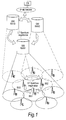
- FIG. 1 shows one way in which multiple RANs can be co-ordinated.
- an overall system is constituted by a number of Radio Access Networks RAN1, RAN2 and RAN3 which each comprise a Gateway GW for the purpose of accessing the RAN from a higher Core Network CN 6, typically via an IP Network.
- the GW is responsible for long-term spectrum assignment (see below) and for at least part of the radio resource management (RRM) in its RAN. It is assumed that one GW is assigned for each RAN.
- RRM radio resource management
- Each RAN may also comprise one or more Base Stations (BS) exemplified in the Figure by BS1, BS2, BS3, each of which is connected to at least one GW.
- BS Base Stations
- Each such BS may transmit (and receive) radio signals to (and from) one or more User Equipments (UEs), within its geographical area of coverage (often referred to as a "cell").
- UEs may also be referred to as user terminals (UTs), terminal equipments (TEs) or Mobile Stations (MSs). Since both base stations and user terminals are equipped to transmit and receive signals over one or more of the RANs, they are sometimes referred to below collectively as transceivers.
- base stations and their UEs may be grouped into "clusters" extending over one or more adjacent or even non-adjacent cells, for spectrum allocation purposes.
- Communications between the CN, GWs and BSs may be across wired communication links (e.g. via fiber-optic links) or across wireless communication links (e.g. across radio or microwave links).
- the GWs communicate among themselves, for example for the purpose of long-term (LT) spectrum assignment, as will be explained later.
- the BSs communicate among themselves for, among other things, short term (ST) spectrum assignment as will also be explained below. Communications between the BSs and the UEs are typically across wireless links.
- the CN may be distributed, for example across the IP network.
- the IP network may, for example, include the Internet.
- three RANs are shown in Figure 1 , the network may include any number of such RANs.
- each RAN may have any number of GWs, BSs and UEs.
- the UEs may be mobile and move from the cell of one BS to that of another BS, and even from one RAN to another RAN.
- the BSs may be dedicated to a particular RAN, or may be shared between RANs on a temporary or non-temporary basis.
- One BS may for example serve two RANs at the same time.
- the RANs in Figure 1 are made up of the same component apparatuses, they may employ different radio access technologies.
- different RANs may be operated by different mobile-network operators.
- Different RANs and BSs may have separate geographical areas of coverage, or may have partially or fully-overlapping areas of coverage.
- one RAN may effectively be co-located with another RAN, perhaps by siting their respective base stations at the same sites or in the same housings.
- radio access network or RAN also encompasses a wireless sensor network (WSN) in which the nodes are sensors of some kind, configured to at least act as transmitters (and sometimes also act as receivers).
- WSN wireless sensor network
- One special form of wireless sensor network is a so-called Body Area Network or BAN, in which sensors are placed at one or more positions on or in living bodies for the purpose of monitoring medical parameters or bodily activity.
- Two forms of BAN are MBAN or Medical BAN for use in hospitals and other health-related applications, and Wireless BAN or WBAN, this more general designation also extending to security applications for example.
- interference management also referred to below as interference mitigation, is essential for allowing efficient sharing and utilization of spectrum between co-existing RANs.
- interference temperature has been proposed for use in managing interference between different RANs. This concept uses the fact that it is the interference level at the affected receiver, rather than at the transmitter causing the interference, which is important to determine the impact of a transmission on other networks.
- By limiting the total interference experience at a given receiver it is possible to allow transmitters to operate in frequency bands (sub-channels or chunks) already allocated to other RANs whilst protecting those other networks from undue interference. In practice, it is unrealistic to expect each transmitter to obtain the necessary information for estimating how their emissions would affect the interference temperature of nearby receivers.
- the concept of "interference temperature” is useful for classifying the level of interference experienced in particular frequency bands by receivers and groups (e.g. clusters) of receivers.
- Efficient coordination between interference control agents in co-existing RANs can contribute to a better quality-of-service (QoS) across all the involved RANs.
- QoS quality-of-service
- the inventor of the present invention has recently proposed a semi-distributed cluster wide approach for dynamic channel allocation and so-called gateway centralised interference mitigation to permit efficient interference management within a RAN.
- an outstanding problem is that on some occasions any one GW in isolation might be unable to have full control on interference inflicted on its own RAN from other RANs. The reason for this is that it can only control the sub-channel allocation in its own RAN, and has no influence on other RANs' interference mitigation and sub-channel allocation processes. It is desirable to overcome this shortcoming by providing efficient methods for a GW-to-GW coordination for an efficient interference mitigation and radio sub-channel allocation.
- an interference mitigation method for use in a wireless communication system formed by a plurality of radio access networks, each radio access network having a network manager arranged for communication with a plurality of nodes associated with the network manager, and each radio access network having a frequency spectrum divisible into a plurality of sub-channels used for wireless communication by the nodes, the frequency spectrum at least partly overlapping with the frequency spectrum of one or more of the other radio access networks; the method comprising the steps of: the network manager of each radio access network performing a spectrum assignment process for allocation of sub-channels to its nodes; the nodes of each radio access network performing wireless communication using their allocated sub-channels; the network manager of one radio access network receiving, from its associated nodes, data indicative of an actual level of interference being experienced by the nodes, the interference arising either internally within the radio access network or externally from the other radio access networks; the network manager of the one radio access network comparing the actual level of interference with an estimated level of interference arising internally within the radio access network to determine
- the comparing step involves determining whether the actual level of interference exceeds the estimated level by at least a threshold amount.
- the network manager of the one radio access network determines there is no need for coordination with another radio access network to reduce the interference, the network manager performs again the spectrum assignment process to its associated nodes in an attempt to reduce the interference arising internally within the radio access network.
- the receiving step is preferably initiated by the network manager obtaining the estimated level of interference, detecting that the estimated level exceeds a predetermined level, and requesting the nodes to send the data indicative of the actual level of interference.
- the data indicative of the actual level of interference being experienced by the nodes preferably includes data on each sub-channel affected by interference. More particularly, it may include an identification of sub-channels consistently affected by interference over successive time periods used for communication in the radio access network.
- the network manager of the one radio access network preferably compiles a list of affected sub-channels and notifies the list to the network manager of the at least one other radio access network. Then, the network manager of the other radio access network performs the spectrum assignment process based on the list of affected sub-channels.
- the network manager of the one radio access network may further notify the list to a spectrum manager of the wireless communication system, the spectrum manager setting guard bands in the frequency spectrum for one or more of the radio access networks based on the list of affected sub-channels.
- the network manager of the one radio access network further notifies the list to a sharing entity of the wireless communication system, the sharing entity determining sharing of the frequency spectrum or defining spectrum boundaries for the radio access networks based on the list of affected sub-channels.
- the interference arising externally can include interference caused by assigning the same sub-channels to nodes in different radio access networks, and the network manager of the other radio access network may attempt to perform the spectrum assignment process to its associated nodes by avoiding the affected sub-channels.
- the network manager of the other radio access network first attempts to perform the spectrum assignment completely, considering all possible combinations of the remaining sub-channels, and if this is not possible, performs the spectrum assignment so as to avoid as many as possible of the affected sub-channels.
- the network manager of the other radio access network performs the spectrum assignment by assigning on a random basis the sub-channels other than the affected sub-channels to its associated nodes.
- the network manager of the other radio access network performs the spectrum assignment process by considering also interference experienced by its associated nodes.
- the network manager of the other radio access network may inform the network manager of the one radio access network of completion of performing again the spectrum assignment process.
- At least one of the radio access networks is a cellular mobile communication system.
- At least one such mobile communication system may be a WINNER system, the network manager of which is a gateway of the WINNER system.
- the spectrum assignment process performed by the gateway is preferably a dynamic radio channel allocation process of assigning sub-channels to nodes on a time scale shorter than long-term and short-term spectrum assignment.
- At least one of the radio access networks is a satellite-based network, or an industrial, scientific and medical band network, or a body area network.
- the nodes will usually include base stations of the radio access network in which they are comprised, each base station performing a resource allocation process to connected user terminals of the base station using the sub-channels allocated by the network manager.
- the nodes will include user terminals of the radio access network in which they are comprised.
- a wired link may be provided for communication between each network manager and its associated nodes.
- a wireless link can be used for this.
- a wireless communication system comprising a plurality of radio access networks, each radio access network having a network manager associated with a plurality of nodes in communication with the network manager, and each radio access network having a frequency spectrum divisible into a plurality of sub-channels for use in wireless communication by the nodes, the frequency spectrum at least partly shared with the other radio access networks; wherein the network manager of each radio access network comprises: spectrum assignment means for allocation of sub-channels to its nodes; interference estimating means for estimating a level of interference expected to arise internally within the radio access network during the wireless communication; comparing means for comparing the estimated level of interference with an actual level of interference affecting the nodes associated with the network manager; and notifying means operable, in the event that the actual level exceeds the estimated level by more than a predetermined threshold, to notify at least one of the other network managers of an interference state; wherein the spectrum assignment means is responsive to a request from any other network manager to repeat the allocation of sub-channels to its nodes
- At least one of the radio access networks is a mobile communication system in which the nodes are transceivers. More particularly, at least one such mobile communication system may be a WINNER network in which the network manager is a WINNER gateway and the transceiver nodes include base stations of the WINNER network.
- At least one of the radio access networks is a wireless sensor network.
- This can include a body area network in which the nodes include sensors acting at least as transmitters in the network.
- RFID devices may act as the nodes.
- a network manager of one of a plurality of radio access networks making up a wireless communication system comprising: means for communicating over a wired or wireless link with each of a plurality of nodes associated with the network manager; spectrum assignment means for allocating sub-channels, within a frequency spectrum available for use by the radio access network and at least partly shared with the other radio access networks, to the nodes for their use in wireless communication; interference estimating means for estimating a level of interference expected to arise internally within the radio access network in the course of the wireless communication; comparing means for comparing the estimated level of interference with an actual level of interference experienced by the nodes in the course of the wireless communication, including both interference arising internally within the radio access network and interference inflicted externally from the other radio access networks; and notifying means operable, in the event that the actual level exceeds the estimated level by more than a predetermined threshold, to notify at least one of the other network managers of an interference state; wherein the spectrum assignment means is responsive to a notification from
- the network manager may be contained in a gateway of a WINNER radio access network.
- wireless communication system is used to denote an overall grouping of radio access networks - RANs - within a particular region of geography or space, each RAN including all of the elements of the network, for example base stations.
- An example of a RAN would be an OFDM-based system of the kind proposed in WINNER, in which spectrum assignment is made in terms of "chunks" each consisting of a rectangular space-time area that comprises a number of OFDM symbols and a number of adjacent subcarriers. In such a system, data transmissions occurs in time units of "frames" each containing a number of chunks.
- Another example of a RAN would be the body area network or BAN mentioned above.
- frequency spectrum radio frequencies or any other range of frequencies of electromagnetic radiation suitable for communication, for example, the radio frequency range of the electromagnetic spectrum.
- the RANs may operate within a microwave frequency range, for example.
- the term “radio” in “radio access network” is thus to be interpreted broadly. At least part of the spectrum may be common or shared among the RANs thus leading to the potential for interference.
- sub-channel is meant primarily a subdivision of the available frequency spectrum along the frequency axis; however, the division is usually made also on a time basis, and possibly also on a spatial basis (particularly where multiple antennas are employed).
- sub-channel is thus to be interpreted broadly as meaning any subdivision of the available radio resources in a RAN.
- node relates to wireless equipment which is capable of undertaking wireless communications within one or more of the RANs, or in other words any radio entity in a RAN.
- a node should be capable of at least transmitting data to the network manager.
- the nodes will be transceivers capable of both receiving and transmitting information, and typically, they will be base stations in a mobile communication system.
- a node may be an RFID device such as tag or a tag reader, or a sink or wireless sensor network base station.
- the nodes may be sensors on or in a particular body being monitored, each such body typically having its own BAN.
- nodes of the above aspects are base stations, these sub-allocate resources to any user terminals which may be connected to them, and such sub-allocation may proceed independently of the present invention.
- node may also relate to the user terminals themselves, for example a mobile telephone, personal digital assistant, laptop or PC, to an RFID tag/node or wireless sensor node, where these have sufficient functionality to communicate directly with the network manager.
- network manager covers any supervisory entity in a RAN, for example a gateway (GW) as provided in a WINNER RAN.
- GW gateway
- a system for spectrum sharing and coexistence of system apparatuses, including the possibility of spectrum exchange between two or more RANs has been considered, for the purposes of attaining better utilisation of spectrum for wireless mobile networks.
- An example of such a system is the WINNER project already mentioned, which is currently under development.
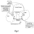
- Figure 2 is a schematic diagram of simplistic network architecture useful for understanding the concept of spectrum sharing.
- the network of Figure 2 may to some extent be compared to the schematic diagram of Figure 1 .
- the basic idea is to enable independent RANs (Radio Access Networks) to use each other's spectrum when it is not needed.
- Negotiations between different RANs may be carried out by communications between the gateways of those RANs.
- the independent RANs may use the same technological standards (radio access technology), as envisaged in WINNER for example.
- the RANs may use different standards whilst overlapping or encroaching to some extent in the frequency spectrum each is able to use.
- FIG 2 two RANs are shown, namely RAN 1 and RAN 2, each having a GW and a BS.
- Figure 2 also shows a representative user terminal (user equipment) UT in radio contact with one BS. Communications are possible between the two GWs, either directly or indirectly.
- Both of the GWs have access to a central database, which may for example have a controlling functionality. This can be used for storing a spectrum register at gateway level. In this way, a record can be kept of the sharing of spectrum between systems, for example between RANs or BSs.
- spectrum sharing is envisaged at the gateway level and/or at the base-station level.
- different approaches to spectrum sharing are envisaged.
- One such approach is referred to as horizontal sharing.
- So-called horizontal sharing may be carried out between systems or communication apparatuses of equal status, i.e. where no one network has priority over the others.
- Such horizontal sharing could be performed with or without coordination.
- Coordination may require capabilities for signalling or at least detection of other networks, and may involve coordination based on a predefined set of rules or "spectrum etiquette".
- vertical sharing Another approach to spectrum sharing is referred to as "vertical sharing”. So-called vertical sharing may be carried out between networks or communication apparatuses in which there are clearly established priorities. For example, there may be primary networks that have precedence in accessing the spectrum and secondary networks that may only use the spectrum providing they do not cause harmful interference towards the primary network(s). It is envisaged that spectrum-sharing enabled networks could be either primary or secondary networks as compared to legacy (non-spectrum-sharing enabled) networks. This leads to two types of vertical sharing, the first type (“Vertical Sharing 1" in Figure 2 ) having the spectrum-sharing enabled network as the primary network, and the second type (“Vertical Sharing 2" in Figure 2 ) having the legacy network as the primary network. Any user terminal UT may also be used to make spectral measurements to assist the spectrum-sharing process.
- Figure 2 indicates that both long-term spectrum assignment (LT assignment) and short-term spectrum assignment (ST assignment) may be carried out.
- Spectrum sharing may be used to periodically reassign a portion of the available spectral resources between different RANs.
- spectrum sharing can enable dynamic balancing of spectral resources between networks.
- Such requirements may be financial/commercial requirements, for example relating to a network operator's customer base or market share.
- Such requirements may also be operational requirements, for example relating to loads on the respective networks.
- spectrum sharing may facilitate focused operation of communication networks resulting in limiting overall need for spectral resources.
- spectral resources may be re-assigned according to variations in the aggregate loads on respective networks, thereby enhancing the overall use of spectrum over a number of networks.
- a spectrum-sharing functionality provides a communication network with stable, predictable and reliable access to the spectrum, whilst also reacting quickly to changing spectrum requirements between different networks of the system.
- LT spectrum assignment providing slowly varying, stable spectrum assignments for large geographical areas
- ST spectrum assignment providing short-term modifications of the large-scale solution
- Figure 3 illustrates conceptually how LT and ST spectrum assignment occur in a system of the Figure 1 type.
- BS1 from RAN1, BS2 from RAN2 and BS3 from RAN3 are engaged in ST spectrum negotiations. It is assumed that the spectrum chunk (or other allocation) being exchanged is part of a shared common pool of spectrum. It is also the assumption that unlike each RAN's dedicated spectrum band, for example as explained later with reference to Figure 5 , none of the RANs has a priority in using the common pool.
- Figure 3 (right-hand side) shows an example in which ST spectrum assignment leads to RAN3 taking part of the common pool, assigned in LT spectrum assignment to RAN2, away from RAN2.
- the first stage may be referred to as "spectrum co-existence and sharing".
- RANs for example belonging to different operators
- a typical scenario is shown in Figure 5 .
- Three operators (Operator 1, Operator 2, and Operator 3) each have their own RAN (RAN 1, RAN 2, and RAN 3 respectively).
- Each such RAN has its own dedicated spectrum band (marked "Dedicated” in the Figure) separated from adjacent bands by means of a guard band.
- a shared spectrum band marked "Shared" also exists, which can be made available to any of the RANs in addition to its dedicated spectrum band.
- the shared band need not be contiguous in frequency with the dedicated band.
- the decision regarding the precise final boundaries of spectrum may be location dependent, depending for example on the nature of the area (e.g. metropolitan area, or local area) and on the coordinates of the area. A trade-off between spatial separation and frequency separation may also affect the precise final boundaries of assigned spectrum.
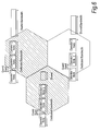
- FIG. 6 This location dependency can be appreciated by reference to Figure 6 .
- three geographical areas of coverage, known as cells, are shown.
- the three RANs of the three operators have a presence in each of the cells, in other words they overlap geographically, however there are differences between the dedicated and shared spectrum allocations for the three RANs that move from cell to cell. That is, the initial boundaries of available spectrum (assuming that some spectrum sharing or reassignment will take place) are different from cell to cell.
- the second stage shown in Fig. 4 is the long-term (LT) spectrum assignment mentioned earlier.
- negotiations can occur between the GWs of different RANs (for example, belonging to different operators) on a regular or semi-regular basis, for example every couple of minutes.
- Such negotiations can serve to rearrange (re-allocate, or re-assign) the available spectrum to ideally maximize spectrum utilization between the different RANs, for example between a primary and secondary RAN.
- one RAN operator can trade in unused spectrum to maximize revenue from its own unused spectrum and improve QoS to its own subscribers by obtaining unused spectrum from other operators.
- spectrum sharing need not be influenced by financial factors, and may instead only be influenced by technical factors, for example by a desire to maximize spectrum utilization across several RANs.
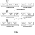
- Figure 7 indicates how spectrum may be re-assigned as part of the second stage.
- this second stage is performed twice by way of a first run and a second run.
- RANs 1 to 3 have a substantially equal dedicated bandwidth, and that RANs 1 and 2 share the extra shared bandwidth, albeit with RAN 2 having the larger such share.
- RAN 2 has increased the size (or frequency range) of its dedicated spectrum allocation by obtaining spectrum from RAN 3.
- RANs 3 and 2 share the extra shared bandwidth (RAN 1 no longer occupying any of the extra shared bandwidth).
- RAN 3 has increased the size of its dedicated spectrum allocation by obtaining spectrum from RAN 2.
- the third stage is the short-term (ST) spectrum assignment referred to above.
- ST short-term
- Such short-term assignment can operate with the spatial granularity of a cell.
- FIG. 8 A possible scenario for the third stage is shown in Figure 8 .
- the left hand part of Figure 8 shows a geographical arrangement of three wide-area deployments or cells (WA 1, WA 2 and WA 3) and a metropolitan area deployment or cell (MA).
- WA 1, WA 2 and WA 3 wide-area deployments or cells
- MA metropolitan area deployment or cell
- the MA occupies a relatively small spectrum portion between portions of spectrum allocated or pre-assigned to WA 1.
- the MA progressively negotiates to obtain spectrum from the wide-area cells.
- the fourth stage may be referred to as channel allocation/radio-resource partitioning.
- This stage decides which sub-channel should be allocated to which radio entity, and can be performed either in distributed manner (e.g. by the base stations) or centralized manner (by the GW).
- decisions can be made in the fourth stage to allocate suitable sub-channels to each cell or base station on an extremely short-term basis, for example every couple of tens of milliseconds.
- ST short-term
- LT Spectrum Assignment and ST Spectrum Assignment are responsible for defining the amount of spectrum available in the common spectrum pool and shaping the boundaries of spectrum over longer time scales, dynamic channel allocation divides the final available spectrum decided by ST Spectrum Assignment (e.g. just borrowed from another cell) into radio sub-channels and decides which radio sub-channel would be allocated to which radio entity on a fast millisecond timescale, in response to radio channel and traffic variation.
- the sharing of spectrum by co-existing multiple RANs provides the potential for signals from one RAN to inflict interference on other RANs.
- the present invention therefore proposes methods to coordinate interference mitigation beyond a gateway on an intra network (GW-to-GW) basis.
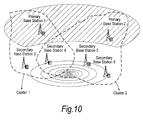
- FIG. 10 shows a Cluster 1 having a lead or primary BS 1 along with other or secondary BSs 3 and 4.
- a Cluster 2 has a Primary BS 2 together with secondary BS 5 and 6 and, in common with Cluster 1, includes Secondary BS 4.
- red and blue GWs relate to the concept of interference temperature as mentioned above.
- a red GW is one whose RAN, or more correctly whose base stations within the RAN, experience (at least within a given frequency band and time duration) an unacceptably high level of interference.
- a blue GW is one for which the interference level in its associated RAN and BSs is acceptable. Entities (including sub-channels) in the network which suffer interference are also referred to below as "troubled”.
- Figure 11 shows the kind of situation which can occur if dynamic sub-channel allocation takes place only at the level of the individual gateway ("GW-centralized").
- the arrows represent the potential communications and interfaces between the GWs and BS. It could happen, for example, that while the RANs assigned to GW 2 and GW 3 are in a low interference (blue) state, the RAN assigned to GW1 is partially or fully in a high interference (red) state. This could occur because GW-centralized channel allocation has no control on the dynamic interference mitigation or sub-channel allocation within other RANs involved in the spectrum sharing process.
- the radio network consists of J transceiver nodes, for example BSs of a mobile communication network. These transceivers are fixed or they can move. They are distributed uniformly in a square region of dimension L ⁇ L . It is assumed that transceivers have the capability to listen to the sub-channels and measure the interference receiver from other transceivers on each radio sub-band. It is further assumed that the radio sub-channels are shared between the transceivers and if the two transceivers choose the same radio sub-channel it will have some impact on both depending on the radio channel between them.
- N transceivers form a cluster of transceivers (see Figure 10 ). It is assumed that overall available spectrum has been divided into P sub channels and each transceiver might transmit at each time in M sub-channels so that M ⁇ P.
- d ki is the amount of data currently residing in the k th buffer of the i th base station.
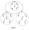
- FIG. 12 conceptually shows three co-existing RANs having respective GWs GW1, GW2 and GW3.
- the RANs are shown in a separate but proximate bordering relationship with each other, but this is purely figurative.
- the RANs may overlap partly or completely in their geographical regions
- Step1 The gateway of one particular RAN, for example GW1 in Figure 12 , determines the current level of total interference ⁇ inflicted on BSs in its RAN based on current interference level and link gains. If the total interference is above a critical threshold, the GW1 declares itself "red" or interference critical. GW1 may be partially in an interference-critical state, for example in neighbouring regions to GW2 and GW3.
- Step 2 As shown in Figure 12 , the gateway GW1 asks its assigned BSs to report their own interference measurement (or an indication of total interference in each BS) on them. In addition, if it has not already done so GW1 calculates an estimate of total interference arising within the RAN, along the lines given in the above theoretical discussion.
- Step 3 The BSs provide this information to the GW1 as shown in Figure 13 .
- the BSs are shown individually providing this information to their GW; alternatively, it would be possible for specific BSs (such as a "Primary" base station illustrated in Figure 10 ) to respond on behalf of the other BSs.
- Step 4 (a) The GW (GW1 in Fig. 13 ) compares the estimated total interference to the sum of all the interferences measured and reported by its associated BSs. (b) If the difference is not significant, the GW assumes that the red situation is caused by a non-optimal centralised dynamic channel allocation attempt; in other words, that the interference is arising internally within its own RAN as a result of the current sub-channel assignment among the associated BSs. The GW performs further trials of the centralized dynamic channel allocation process. Thus, it attempts to solve the interference-critical state by itself.
- Step 5 If the difference is high and above a pre-assigned threshold, the GW concludes that the problem is coming from the co-existing RANs currently sharing the spectrum with GW1. In that case, GW 1 asks its assigned BSs to report the consistently troubled sub-channels as shown in Figure 14 .
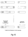
- Figure 15 shows a set of rows each representing the interference experienced at a respective BS.
- the horizontal direction in Figure 15 can be regarded as a frequency axis, and subdivisions of each row are individual subchannels. Note that there is no need for these to be contiguous, as indicated by the gap in each row.
- the troubled sub-channels as shown in Figure 15 are the radio sub-channels which have suffered most from a consistently high amount of interference for, e.g. the past n transmission periods.
- lightly-shaded sub-channels are ones suffering some interference and darker-shaded sub-channels are experiencing high interference ("red").
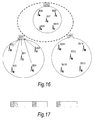
- Step 6 The BSs provide the requested information to the GW as shown in Figure 16 .
- Step 7 Based on the received list of troubled sub-channels, GW 1 constructs a unified list of troubled sub-channels as shown in Figure 17 . In other words, individual BS reports of the form shown in Figure 15 are combined into a single list.
- Step 7 The troubled GW 1 informs other GWs involved in the LT spectrum assignment process that it is in trouble (i.e. red) and is suffering from their interference as shown in Figure 18 .
- GW1 preferably uses the same signalling network as employed during LT spectrum assignment negotiations with the other GWs, such as the IP network indicated in Figure 1 .
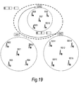
- Step 8 GW 1 then provides the final list of troubled sub-channels to the other GWs involved in the ST and LT spectrum assignment and sharing process, as shown in Figure 19 . Steps 7 and 8 may be combined into a single operation.
- Step 9 Those other GWs (for example GW2 and GW3) perform a new dynamic centralized channel allocation process for their respective associated BSs, thereby achieving interference cancellation based on the knowledge of the troubled channels in the suffering GW.
- GW2 and GW3 perform a new dynamic centralized channel allocation process for their respective associated BSs, thereby achieving interference cancellation based on the knowledge of the troubled channels in the suffering GW.
- Step 10 The other GWs (for example GW2 and GW3) process Gateway Requests for current transmission power, current buffer occupancy and current ⁇ ij , where ⁇ ij is the overall transmission gain associated with the link from the transceiver i and transceiver j. This latter information may be already available in the Gateway.
- GW2 and GW3 process Gateway Requests for current transmission power, current buffer occupancy and current ⁇ ij , where ⁇ ij is the overall transmission gain associated with the link from the transceiver i and transceiver j. This latter information may be already available in the Gateway.
- Step 11 The BSs provide the requested information to their Gateway as shown in Figure 15 .
- Step 12 For each of their BSs, the other GWs (for example GW2 and GW3) map the total traffic ⁇ i requiring transmission (in the next transmission period, e.g. frame) to a minimum number of required sub-channels M.
- the other GWs for example GW2 and GW3
- Step 13 The other GWs (GW2 and GW3) consider the potential channel allocation of a number of sub-channels for each BS.
- Step 14 Then the other GWs (GW2 and GW3) consider all the possible combinations of sub-channel allocations to the BSs (e.g. on a random basis) avoiding all the red sub-channels in the list provided by the troubled GW .
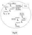
- Step 15 If it is not possible to avoid red sub-channels completely, then the other GWs (for example GW2 and GW3) consider all the combinations of sub-channel allocations to BSs with a minimum number of red sub-channels involved, as shown in Figure 20 .
- the other GWs for example GW2 and GW3
- Step 16 Then the other GWs (for example GW2 and GW3) consider the total interference inflicted on all the BSs assigned to them, and select the combination that minimises ⁇ with a minimum number of red sub-channels and minimum interference on red sub-channels.
- GW2 and GW3 consider the total interference inflicted on all the BSs assigned to them, and select the combination that minimises ⁇ with a minimum number of red sub-channels and minimum interference on red sub-channels.
- Step 17 The other GWs (for example GW2 and GW3) inform their own BS of their preferred sub-channel allocation and the troubled GW1 of the completion of the process as shown in Figure 21 .
- the troubled GW (for example GW1) is no longer suffering interference inflicted from outside its own RAN, or at least has less interference.
- Step 18 GW1 monitors the situation to see whether or not it is still in an interference-critical state. If it is, it repeats the process from the beginning of Figure 22A , perhaps after a time delay.
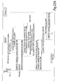
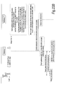
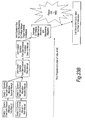
- Figures 22A and B depict the event-triggered process leading to the start of the coordination between the GWs.
- the left-hand vertical line is a time line of actions at the BS level; the centre vertical line shows the sequence of operations in the troubled GW; and the right-hand vertical line shows actions performed in the other gateways.
- Figures 23A and 23B summarise events which can trigger use of the method embodying the present invention.
- Figure 23A shows dynamic allocation on an ms timescale using clusters, the details of which are the subject of a co-pending patent application.
- Fig. 23B if the results of this dynamic allocation fail to resolve the red condition of the clusters, this indicates that interference cannot be sufficiently mitigated at the RAN level, and thus the GW-to-GW coordination according to the present invention is triggered.
- the GW that receives the multiple troubled sub-channel lists creates a new list by combining the received lists as shown in Figure 24 .
- GW1 and GW3 both send information on their troubled sub-channels to GW2 which collates the data into a single combined list.
- the combined list provides a prioritised list of troubled sub-channels as shown in Figure 25 . It helps the GW of interest (GW 2 in Figure 24 ), to identify the most troubled (i.e. overlapped sub-channels) and give them a lower priority when it is about to perform the future dynamic channel allocation with its own BSs.
- this GW can take any of the following further courses of action:
- the present invention is not restricted to radio access networks having distinct base stations as such. It may also be applied to networks in which the functions of base stations are handled in other equipment such as UTs, or in networks such as RFID networks and BANs as already mentioned.
- FIG 30 shows an example of a system of RFID or wireless sensor networks (WSNs) in a similar configuration to Figures 11-14 , 16-19 , and so on.
- WSNs wireless sensor networks
- Figure 30 illustrates three RFID/sensor networks (WSN 1, 2 and 3) each comprising multiple sensors and "sinks" for the sensor data (the sinks are the equivalent of BSs in a wireless communication network).
- WSN 1, 2 and 3 each WSN has a respective GW (GW1, GW2 or GW3) having corresponding functions to the gateways previously described and configured to carry out the above-described method in an analogous fashion.
- Adaptive channel coding rates for a data packet and radio node have been considered to enable the radio nodes to adjust their transmission rates and consequently the target SIR values.
- the BER requirements selected for simulations is 10 -3 , and it is assumed that the use of a Reed-Muller channel code RM(1,m).
- the coding rate combinations and the corresponding SIR target requirements used for the simulations are related as shown in Table 1.
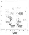
- the main X and Y axes represent distance (e.g. in kilometres) in a geographical region served by two RANs having gateways GW1 and GW2.
- a cluster of BSs (transceivers) is shown, each diamond representing a BS located at a particular geographical position for the purposes of the simulation, above which is schematically shown an interference plot (interference level vs. subchannel number).
- the narrow line bar represents the interference inflicted on other BSs on the current sub-channel.
- the dashed lines represent the interference inflicted on that BS from other BSs on the current sub-channel.
- the lighter patches in the lower part of each interference plot represent blue subchannels.
- the darker patches in the upper part of each plot represent red subchannels. Comparing the arrowed lines marked "Interference Level" in Figure 31A and 31B respectively, indicates a reduction in interference obtained by applying the method of the present invention.
- the method embodying the present invention can provide the following effects:
- the GW provides a means by which the GW can inform other networks (i.e. potential candidate for future long term and short term spectrum sharing) such as Industrial, Scientific and Medical bands (ISM), or fixed satellite services of the most troubled bands within its own network.
- networks i.e. potential candidate for future long term and short term spectrum sharing
- ISM Industrial, Scientific and Medical bands
- the present invention can allow a GW to inform the overall spectrum policy manager of the troubled sub-channels, for consideration in future dynamic planning of guard bands.
- the present invention enables a GW to inform the Spectrum Coexistence and Sharing entity of the most troubled sub-channels, allowing the latter to consider them when defining boundaries of the common pool of spectrum, and when redefining guard bands.
- the method embodying the present invention involves providing a troubled GW providing a final list of troubled sub-channels to other GWs involved in ST and LT spectrum assignment and sharing process.
- the method embodying the present invention uses the concept of coordination between the gateways involved in long term and short term spectrum assignment and sharing processes in terms of the sub- channel allocation and interference mitigation on an intra system or intra RAN basis.
- the method embodying the present invention adopts the idea of interference temperature, defining thresholds for two levels of red (high interference) and blue (low interference) for all the involved gateways.
- the method includes a step of identifying the consistently troubled sub-channels (that is, sub-channels affected by interference, also called “red” sub-channels) in the BSs and sending this information to the network manager (centralized entity) or gateway GW. This "suffering" GW informs other GWs in the system of its problem.
- the method embodying the present invention performs a new dynamic centralized channel allocation process based on the knowledge of the troubled channels in the suffering GW by other GWs involved in the ST and LT spectrum assignment and sharing process.
- the other GWs involved in the ST and LT spectrum assignment and sharing consider all the possible combinations of sub-channel allocations to base stations, avoiding all the red sub-channels in the list provided by the troubled GW as much as they can.
- red sub-channels are unavoidable, other GWs involved in the ST and LT spectrum assignment and sharing process consider all the combinations of sub-channel allocations to their own BSs employing a minimum number of red sub-channels.
- these GWs inform their own BSs of their preferred sub-channel allocation and the troubled GW of the completion of the process
- the various features may be implemented in hardware, or as software modules running on one or more processors.
- the gateway is depicted in the Figures as a single unit for convenience, the functionality of the GW may be distributed over different locations in the network.
- certain functions of the GW could be implemented at the level of the BS or spectrum manager.
- the spectrum manager need not be a single unit but may be distributed, for example partly or wholly within the GWs of each RAN.
- a GW employs one threshold to determine whether to request the BSs to send information on their actual interference levels, and another threshold to determine whether the actual interference significantly exceeds the estimated level.
- more than one threshold may be employed.
- a higher threshold may be used to determine whether to perform GW-to-GW coordination more frequently.
- the claimed wireless communication system and gateway may have any or all of the features of the method and/or system claims.
- the invention also provides a computer program or a computer program product for carrying out any of the methods described herein, and a computer readable medium having stored thereon a program for carrying out any of the methods described herein.
- a computer program embodying the invention may be stored on a computer-readable medium, or it could, for example, be in the form of a signal such as a downloadable data signal provided from an Internet website, or it could be in any other form.
Applications Claiming Priority (1)
| Application Number | Priority Date | Filing Date | Title |
|---|---|---|---|
| GB0801537A GB2457432A (en) | 2008-01-28 | 2008-01-28 | Mitigating interference in wireless communication systems |
Publications (3)
| Publication Number | Publication Date |
|---|---|
| EP2083594A2 true EP2083594A2 (de) | 2009-07-29 |
| EP2083594A3 EP2083594A3 (de) | 2010-04-28 |
| EP2083594B1 EP2083594B1 (de) | 2013-02-13 |
Family
ID=39186453
Family Applications (1)
| Application Number | Title | Priority Date | Filing Date |
|---|---|---|---|
| EP09150211A Expired - Fee Related EP2083594B1 (de) | 2008-01-28 | 2009-01-08 | Verfahren und System für Interferenzreduktion in einem aus mehreren Funkzugangsnetzen gebildeten drahtlosen Kommunikationssystem |
Country Status (4)
| Country | Link |
|---|---|
| US (1) | US8140018B2 (de) |
| EP (1) | EP2083594B1 (de) |
| JP (1) | JP5083232B2 (de) |
| GB (1) | GB2457432A (de) |
Cited By (11)
| Publication number | Priority date | Publication date | Assignee | Title |
|---|---|---|---|---|
| WO2011124995A1 (en) | 2010-04-06 | 2011-10-13 | Koninklijke Philips Electronics N.V. | Centralized dynamic channel allocation for medical body area networks |
| WO2011154612A1 (en) | 2010-06-11 | 2011-12-15 | Teknologian Tutkimuskeskus Vtt | A method and device for selecting one or more resources for use from among a set of resources |
| WO2012091160A1 (en) * | 2010-12-27 | 2012-07-05 | Panasonic Corporation | Radio base station, radio communication terminal, radio communication system, radio communication method and communication management method, using allocation of shared frequency |
| WO2012173549A3 (en) * | 2011-06-17 | 2013-03-21 | Telefonaktiebolaget L M Ericsson (Publ) | Radio resource sharing in a local radio environment |
| EP2592855A1 (de) * | 2010-08-18 | 2013-05-15 | ZTE Corporation | Verfahren und vorrichtung für spektrenzuweisung |
| EP2603030B1 (de) * | 2011-12-09 | 2014-12-24 | Fujitsu Limited | Störungsmanagement in drahtlosen Kommunikationsnetzwerken |
| US9037179B2 (en) | 2011-06-17 | 2015-05-19 | Telefonaktiebolaget L M Ericsson (Publ) | Method and network node in a wireless communication system |
| EP2779728A4 (de) * | 2012-04-20 | 2015-05-27 | Huawei Tech Co Ltd | Verfahren und vorrichtung für dynamische gemeinsame spektrumsnutzung |
| US9231709B2 (en) | 2010-03-31 | 2016-01-05 | The Hong Kong University Of Science And Technology | Transmitting and/or receiving data in a side channel |
| CN105792224A (zh) * | 2014-12-26 | 2016-07-20 | 上海无线通信研究中心 | 一种网络间干扰协调方法 |
| WO2018085633A1 (en) * | 2016-11-03 | 2018-05-11 | Qualcomm Incorporated | Coverage contour and interference thresholds for channel assignment |
Families Citing this family (42)
| Publication number | Priority date | Publication date | Assignee | Title |
|---|---|---|---|---|
| JP5178915B2 (ja) * | 2008-09-05 | 2013-04-10 | テレフオンアクチーボラゲット エル エム エリクソン(パブル) | セカンダリ使用のための送信の調整 |
| KR101558238B1 (ko) * | 2009-08-04 | 2015-10-08 | 삼성전자주식회사 | 인지 무선 통신 장치 및 인지 무선 통신 장치의 무선 접속 기술 선택 방법 |
| JP5358737B2 (ja) | 2009-09-09 | 2013-12-04 | エルジー エレクトロニクス インコーポレイティド | 無線ranシステムにおけるチャネルスキャニング方法 |
| KR101643937B1 (ko) * | 2009-10-20 | 2016-08-10 | 삼성전자주식회사 | 다중 입출력 무선통신 시스템에서 셀 간 간섭을 제거하기 위한 장치 및 방법 |
| WO2011049314A2 (en) | 2009-10-21 | 2011-04-28 | Lg Electronics Inc. | Method and apparatus for scanning existing networks in tvws |
| NL2003736C2 (en) | 2009-10-30 | 2011-05-03 | Ambient Systems B V | Communication method for high density wireless networks, terminal, cluster master device, central node, and system therefor. |
| JP5329389B2 (ja) * | 2009-12-28 | 2013-10-30 | 株式会社ウィルコム | 無線通信システムの周波数資源割り当て方法およびそのシステム |
| KR101430499B1 (ko) | 2010-03-12 | 2014-08-14 | 엘지전자 주식회사 | 무선 통신 시스템에서 주된 서비스를 보호하기 위한 방법 및 장치 |
| JP5660426B2 (ja) * | 2010-03-17 | 2015-01-28 | 独立行政法人情報通信研究機構 | 無線通信システム |
| WO2011115449A2 (en) | 2010-03-19 | 2011-09-22 | Lg Electronics Inc. | Method and apparatus for acquiring available channel information in a wireless local area network system |
| JP5518251B2 (ja) | 2010-04-07 | 2014-06-11 | エルジー エレクトロニクス インコーポレイティド | 無線lanシステムでホワイトスペースマップ情報を伝送及び受信するための方法及び装置 |
| CN102845089B (zh) * | 2010-04-13 | 2016-11-16 | 皇家飞利浦电子股份有限公司 | 具有自动的机构内频谱使用管制的医学人体区域网(mban) |
| RU2580069C2 (ru) * | 2010-04-13 | 2016-04-10 | Конинклейке Филипс Электроникс Н.В. | Медицинская сеть около тела (mban) с основанным на ключе управлением использованием спектра |
| JP5586047B2 (ja) * | 2010-05-14 | 2014-09-10 | 独立行政法人情報通信研究機構 | 無線通信方法及びシステム |
| WO2011145796A1 (en) | 2010-05-18 | 2011-11-24 | Lg Electronics Inc. | Method and apparatus for dynamic station enablement procedure in a wireless local area network system |
| WO2011155693A2 (en) | 2010-06-07 | 2011-12-15 | Lg Electronics Inc. | Method and apparatus for a station to operate within wlan system |
| US9107232B2 (en) * | 2010-12-10 | 2015-08-11 | Qualcomm Incorporated | Interference management between multiple networks |
| WO2012124949A2 (ko) * | 2011-03-11 | 2012-09-20 | 엘지전자 주식회사 | 무선 통신 시스템에서 채널 정보를 송수신하는 방법 및 장치 |
| CN103548370B (zh) * | 2011-05-19 | 2017-08-11 | 日本电气株式会社 | 频谱控制系统、频谱控制方法、无线通信系统 |
| CN102857930A (zh) | 2011-06-30 | 2013-01-02 | 国际商业机器公司 | 用于基于ofdm的无线通信系统的共享频率的方法和设备 |
| US9345030B2 (en) | 2011-08-11 | 2016-05-17 | Panasonic Intellectual Property Management Co., Ltd. | White space sharing based on priority of competing applications |
| WO2013045741A1 (en) * | 2011-09-28 | 2013-04-04 | Nokia Siemens Networks Oy | Inter-system interference in communications |
| BR112014013389A2 (pt) * | 2011-12-05 | 2017-06-13 | Koninklijke Philips Nv | sistema de transmissão de chave eletrônica de uma instituição médica, método para transmissão de uma chave eletrônica através de uma instituição médica, e, mídia legível em computador não transitória |
| US8929934B2 (en) * | 2012-04-25 | 2015-01-06 | Intel Mobile Communications GmbH | Communication devices and methods for operating a communication device |
| CN104396292B (zh) * | 2012-05-04 | 2018-05-11 | 诺基亚通信公司 | 在无线通信系统之间的共享频带的配置 |
| WO2014094214A1 (en) * | 2012-12-17 | 2014-06-26 | France Telecom | A dynamic spectrum access method, corresponding device, computer program product |
| WO2015004815A1 (ja) | 2013-07-12 | 2015-01-15 | 富士通株式会社 | 通信方法、通信システム、制御装置および無線装置 |
| US9635560B2 (en) * | 2013-08-05 | 2017-04-25 | Qualcomm Incorporated | Verification of authorized shared access operation |
| KR101530375B1 (ko) * | 2013-09-27 | 2015-06-22 | (주)주니코리아 | 간섭완화시스템 및 간섭완화방법 |
| ES2532518B1 (es) * | 2013-09-27 | 2016-01-19 | Vodafone España, S.A.U. | Elemento de red y procedimiento para coordinar el uso de recursos radio entre redes de acceso radio |
| US9854597B2 (en) | 2013-10-02 | 2017-12-26 | Cellos Software Ltd | Method and communication apparatus for resource allocation in wireless communication network |
| US10021697B2 (en) * | 2014-02-07 | 2018-07-10 | Qualcomm Incorporated | Multi-tiered shared access operation |
| US9788211B2 (en) | 2014-03-05 | 2017-10-10 | Huawei Technologies Co., Ltd. | System and method for a customized fifth generation (5G) network |
| US10111235B2 (en) | 2016-02-15 | 2018-10-23 | Spidercloud Wireless, Inc. | Methods for centralized channel selection across different cells in a radio access network |
| US20170295578A1 (en) * | 2016-04-06 | 2017-10-12 | Qualcomm Incorporated | Bandwidth expansion in channel coexistence |
| WO2019058331A1 (en) * | 2017-09-21 | 2019-03-28 | Telefonaktiebolaget Lm Ericsson (Publ) | METHOD AND APPARATUS FOR MANAGING BAND INTERFERENCE CONNECTION TYPES FOR BROADBAND BANALIZED RADIO SERVICE DEVICES |
| US10841805B2 (en) * | 2017-10-10 | 2020-11-17 | Qualcomm Incorporated | Inter-operator coordination for channel access in shared spectrum |
| US10251069B1 (en) | 2018-03-28 | 2019-04-02 | Fairspectrum Oy | Method and system for allocating frequency ranges to plurality of networks |
| US10638512B2 (en) * | 2018-05-09 | 2020-04-28 | Verizon Patent And Licensing Inc. | Multiplexing multi-radio access technology transmissions |
| WO2020170269A1 (en) * | 2019-02-19 | 2020-08-27 | Indian Institute Of Technology Madras | Simultaneous sharing of spectrum in wireless communications |
| US11863996B2 (en) * | 2019-03-08 | 2024-01-02 | Samsung Electronics Co., Ltd. | Centralized coordination for shared spectrum systems |
| CN110138535B (zh) * | 2019-06-04 | 2022-01-25 | 西安易朴通讯技术有限公司 | 数据传输方法及装置 |
Family Cites Families (13)
| Publication number | Priority date | Publication date | Assignee | Title |
|---|---|---|---|---|
| US5548809A (en) * | 1992-07-15 | 1996-08-20 | Southwestern Bell Technology Resources, Inc. | Spectrum sharing communications system and system for monitoring available spectrum |
| US6909879B1 (en) * | 2000-08-22 | 2005-06-21 | Cellco Partnership | Methods and apparatus for utilizing radio frequency spectrum simultaneously and concurrently in the presence of co-channel and/or adjacent channel television signals |
| US7177598B2 (en) * | 2000-11-15 | 2007-02-13 | Wi-Lan, Inc. | Method and system for reducing channel interference in a frame-synchronized wireless communication system |
| US20020155811A1 (en) * | 2001-04-18 | 2002-10-24 | Jerry Prismantas | System and method for adapting RF transmissions to mitigate the effects of certain interferences |
| ATE393514T1 (de) | 2001-09-14 | 2008-05-15 | Ericsson Telefon Ab L M | Drahtloses kommunikationssystem mit erkennung von fremdstrahlungsquellen |
| US7242907B2 (en) * | 2001-12-10 | 2007-07-10 | Harris Corporation | System and method for inband signaling for sector synchronization in a wireless communication system |
| JP3842666B2 (ja) | 2002-02-20 | 2006-11-08 | 株式会社エヌ・ティ・ティ・ドコモ | 基地局及び通信方法 |
| CA2490882A1 (en) | 2002-06-28 | 2004-01-08 | Interdigital Technology Corporation | Method and system for determining correct escape mechanisms and controlling interference in third generation wireless systems |
| EP1732338A4 (de) | 2004-03-05 | 2011-06-29 | Ntt Docomo Inc | Frequenzkanal-zuweisungssystem, basisstation, steuerstation, gemeinsame steuervorrichtung zwischen systemen, frequenzkanal-zuweisungsverfahren und steuerverfahren |
| US8355748B2 (en) | 2004-05-28 | 2013-01-15 | Panasonic Corporation | Multi-mode control station, radio communication system, radio station, and radio communication control method |
| TWI521920B (zh) * | 2004-10-20 | 2016-02-11 | 高通公司 | 無線網路中之多頻帶操作 |
| EP1659814A1 (de) | 2005-10-27 | 2006-05-24 | Siemens Aktiengesellschaft | Verfahren zur Intersystem-Interferenzunterdrückung zwischen zumindest zwei Funkübertragungsverfahren |
| FI20065269A0 (fi) | 2006-04-26 | 2006-04-26 | Nokia Corp | Spektrin käyttö radiojärjestelmässä |
-
2008
- 2008-01-28 GB GB0801537A patent/GB2457432A/en not_active Withdrawn
- 2008-12-17 US US12/314,842 patent/US8140018B2/en not_active Expired - Fee Related
-
2009
- 2009-01-08 EP EP09150211A patent/EP2083594B1/de not_active Expired - Fee Related
- 2009-01-27 JP JP2009015920A patent/JP5083232B2/ja not_active Expired - Fee Related
Non-Patent Citations (1)
| Title |
|---|
| None |
Cited By (25)
| Publication number | Priority date | Publication date | Assignee | Title |
|---|---|---|---|---|
| US9231709B2 (en) | 2010-03-31 | 2016-01-05 | The Hong Kong University Of Science And Technology | Transmitting and/or receiving data in a side channel |
| CN102823293B (zh) * | 2010-04-06 | 2015-12-09 | 皇家飞利浦电子股份有限公司 | 用于医疗体域网的动态信道选择 |
| CN102823293A (zh) * | 2010-04-06 | 2012-12-12 | 皇家飞利浦电子股份有限公司 | 用于医疗体域网的集中式动态信道分配 |
| WO2011124995A1 (en) | 2010-04-06 | 2011-10-13 | Koninklijke Philips Electronics N.V. | Centralized dynamic channel allocation for medical body area networks |
| RU2576475C2 (ru) * | 2010-04-06 | 2016-03-10 | Конинклейке Филипс Электроникс Н.В. | Централизованное динамическое выделение каналов для внутренних сетей медицинского учреждения |
| WO2011154612A1 (en) | 2010-06-11 | 2011-12-15 | Teknologian Tutkimuskeskus Vtt | A method and device for selecting one or more resources for use from among a set of resources |
| US11129137B2 (en) | 2010-06-11 | 2021-09-21 | Teknologian Tutkimuskeskus Vtt Oy | Method and device for selecting one or more resources for use from among a set of resources |
| EP2580926A4 (de) * | 2010-06-11 | 2017-08-16 | Teknologian Tutkimuskeskus VTT | Verfahren und vorrichtung zur auswahl einer oder mehrerer ressourcen zur verwendung in einem satz von ressourcen |
| US10015777B2 (en) | 2010-08-18 | 2018-07-03 | Zte Corporation | Method and apparatus for allocating spectrum |
| EP2592855A1 (de) * | 2010-08-18 | 2013-05-15 | ZTE Corporation | Verfahren und vorrichtung für spektrenzuweisung |
| EP2592855A4 (de) * | 2010-08-18 | 2017-05-03 | ZTE Corporation | Verfahren und vorrichtung für spektrenzuweisung |
| GB2500836A (en) * | 2010-12-27 | 2013-10-02 | Panasonic Corp | Radio base station, radio communication terminal, radio communication system, radio communication method and communication management method, using allocation |
| US8792923B2 (en) | 2010-12-27 | 2014-07-29 | Panasonic Corporation | Radio base station, radio communication terminal, radio communication system, radio communication method and communication management method, using allocation of shared frequency |
| WO2012091160A1 (en) * | 2010-12-27 | 2012-07-05 | Panasonic Corporation | Radio base station, radio communication terminal, radio communication system, radio communication method and communication management method, using allocation of shared frequency |
| GB2500836B (en) * | 2010-12-27 | 2015-01-07 | Panasonic Corp | Radio base station, terminal, system and method using allocation of shared frequency utilizing white space in addition to dedicated frequency |
| WO2012173549A3 (en) * | 2011-06-17 | 2013-03-21 | Telefonaktiebolaget L M Ericsson (Publ) | Radio resource sharing in a local radio environment |
| US9037179B2 (en) | 2011-06-17 | 2015-05-19 | Telefonaktiebolaget L M Ericsson (Publ) | Method and network node in a wireless communication system |
| US9020546B2 (en) | 2011-12-09 | 2015-04-28 | Fujitsu Limited | Interference management in wireless communication networks |
| EP2603030B1 (de) * | 2011-12-09 | 2014-12-24 | Fujitsu Limited | Störungsmanagement in drahtlosen Kommunikationsnetzwerken |
| EP2779728A4 (de) * | 2012-04-20 | 2015-05-27 | Huawei Tech Co Ltd | Verfahren und vorrichtung für dynamische gemeinsame spektrumsnutzung |
| CN105792224A (zh) * | 2014-12-26 | 2016-07-20 | 上海无线通信研究中心 | 一种网络间干扰协调方法 |
| EP3240320A4 (de) * | 2014-12-26 | 2018-08-01 | Shanghai Research Centre For Wireless Communication | Verfahren zur koordinierung von netzwerkübergreifenden interferenzen |
| CN105792224B (zh) * | 2014-12-26 | 2019-06-04 | 上海无线通信研究中心 | 一种网络间干扰协调方法 |
| WO2018085633A1 (en) * | 2016-11-03 | 2018-05-11 | Qualcomm Incorporated | Coverage contour and interference thresholds for channel assignment |
| US10448401B2 (en) | 2016-11-03 | 2019-10-15 | Qualcomm Incorporated | Coverage contour and interference thresholds for channel assignment |
Also Published As
| Publication number | Publication date |
|---|---|
| EP2083594B1 (de) | 2013-02-13 |
| JP5083232B2 (ja) | 2012-11-28 |
| GB0801537D0 (en) | 2008-03-05 |
| JP2009177816A (ja) | 2009-08-06 |
| EP2083594A3 (de) | 2010-04-28 |
| GB2457432A (en) | 2009-08-19 |
| US8140018B2 (en) | 2012-03-20 |
| US20090191906A1 (en) | 2009-07-30 |
Similar Documents
| Publication | Publication Date | Title |
|---|---|---|
| EP2083594B1 (de) | Verfahren und System für Interferenzreduktion in einem aus mehreren Funkzugangsnetzen gebildeten drahtlosen Kommunikationssystem | |
| US8023898B2 (en) | Communication systems | |
| US8422453B2 (en) | Communication systems | |
| US10021702B2 (en) | Measurement-assisted dynamic frequency-reuse in cellular telecommunications networks | |
| US8478283B2 (en) | Method and system for capacity and coverage enhancement in wireless networks with relays | |
| US20090161617A1 (en) | Communication Systems | |
| EP2083593B1 (de) | Verfahren, Vorrichtung und Computerprogramm zum Steuern der Spektrumbenutzung durch Austausch von Spektrumsteilen zwischen drahtlosen Kommunikationssystemen | |
| US20130090120A1 (en) | Inter-cell interference coordination in wireless networks | |
| JP5506117B2 (ja) | 重畳無線ネットワーク環境におけるリソース割り当て方法及び装置 | |
| Herranz et al. | Cognitive radio enabling opportunistic spectrum access in LTE-advanced femtocells | |
| JP7409303B2 (ja) | 無線装置、端末、方法およびコンピュータプログラム | |
| Kesanakurthi | Exploiting the ability of self-organizing networks for inter-cell interference coordination for emergency communications in cellular networks |
Legal Events
| Date | Code | Title | Description |
|---|---|---|---|
| PUAI | Public reference made under article 153(3) epc to a published international application that has entered the european phase |
Free format text: ORIGINAL CODE: 0009012 |
|
| AK | Designated contracting states |
Kind code of ref document: A2 Designated state(s): AT BE BG CH CY CZ DE DK EE ES FI FR GB GR HR HU IE IS IT LI LT LU LV MC MK MT NL NO PL PT RO SE SI SK TR |
|
| AX | Request for extension of the european patent |
Extension state: AL BA RS |
|
| PUAL | Search report despatched |
Free format text: ORIGINAL CODE: 0009013 |
|
| AK | Designated contracting states |
Kind code of ref document: A3 Designated state(s): AT BE BG CH CY CZ DE DK EE ES FI FR GB GR HR HU IE IS IT LI LT LU LV MC MK MT NL NO PL PT RO SE SI SK TR |
|
| AX | Request for extension of the european patent |
Extension state: AL BA RS |
|
| 17P | Request for examination filed |
Effective date: 20101025 |
|
| AKX | Designation fees paid |
Designated state(s): DE FR GB |
|
| 17Q | First examination report despatched |
Effective date: 20110620 |
|
| GRAP | Despatch of communication of intention to grant a patent |
Free format text: ORIGINAL CODE: EPIDOSNIGR1 |
|
| RIC1 | Information provided on ipc code assigned before grant |
Ipc: H04W 16/14 20090101AFI20120727BHEP Ipc: H04W 92/02 20090101ALN20120727BHEP |
|
| GRAS | Grant fee paid |
Free format text: ORIGINAL CODE: EPIDOSNIGR3 |
|
| GRAA | (expected) grant |
Free format text: ORIGINAL CODE: 0009210 |
|
| AK | Designated contracting states |
Kind code of ref document: B1 Designated state(s): DE FR GB |
|
| REG | Reference to a national code |
Ref country code: GB Ref legal event code: FG4D |
|
| REG | Reference to a national code |
Ref country code: DE Ref legal event code: R096 Ref document number: 602009013192 Country of ref document: DE Effective date: 20130411 |
|
| PLBE | No opposition filed within time limit |
Free format text: ORIGINAL CODE: 0009261 |
|
| STAA | Information on the status of an ep patent application or granted ep patent |
Free format text: STATUS: NO OPPOSITION FILED WITHIN TIME LIMIT |
|
| 26N | No opposition filed |
Effective date: 20131114 |
|
| REG | Reference to a national code |
Ref country code: DE Ref legal event code: R097 Ref document number: 602009013192 Country of ref document: DE Effective date: 20131114 |
|
| REG | Reference to a national code |
Ref country code: FR Ref legal event code: PLFP Year of fee payment: 8 |
|
| REG | Reference to a national code |
Ref country code: FR Ref legal event code: PLFP Year of fee payment: 9 |
|
| REG | Reference to a national code |
Ref country code: FR Ref legal event code: PLFP Year of fee payment: 10 |
|
| PGFP | Annual fee paid to national office [announced via postgrant information from national office to epo] |
Ref country code: FR Payment date: 20191216 Year of fee payment: 12 |
|
| PGFP | Annual fee paid to national office [announced via postgrant information from national office to epo] |
Ref country code: DE Payment date: 20191224 Year of fee payment: 12 Ref country code: GB Payment date: 20200102 Year of fee payment: 12 |
|
| REG | Reference to a national code |
Ref country code: DE Ref legal event code: R119 Ref document number: 602009013192 Country of ref document: DE |
|
| GBPC | Gb: european patent ceased through non-payment of renewal fee |
Effective date: 20210108 |
|
| PG25 | Lapsed in a contracting state [announced via postgrant information from national office to epo] |
Ref country code: FR Free format text: LAPSE BECAUSE OF NON-PAYMENT OF DUE FEES Effective date: 20210131 |
|
| PG25 | Lapsed in a contracting state [announced via postgrant information from national office to epo] |
Ref country code: DE Free format text: LAPSE BECAUSE OF NON-PAYMENT OF DUE FEES Effective date: 20210803 Ref country code: GB Free format text: LAPSE BECAUSE OF NON-PAYMENT OF DUE FEES Effective date: 20210108 |