EP2083526A1 - Method for synchronizing applicative clock signals in a synchronous communications network, corresponding emitter and receiver devices, computer program product and computer-readable storage means. - Google Patents
Method for synchronizing applicative clock signals in a synchronous communications network, corresponding emitter and receiver devices, computer program product and computer-readable storage means. Download PDFInfo
- Publication number
- EP2083526A1 EP2083526A1 EP09150203A EP09150203A EP2083526A1 EP 2083526 A1 EP2083526 A1 EP 2083526A1 EP 09150203 A EP09150203 A EP 09150203A EP 09150203 A EP09150203 A EP 09150203A EP 2083526 A1 EP2083526 A1 EP 2083526A1
- Authority
- EP
- European Patent Office
- Prior art keywords
- data
- applicative
- network
- pieces
- information
- Prior art date
- Legal status (The legal status is an assumption and is not a legal conclusion. Google has not performed a legal analysis and makes no representation as to the accuracy of the status listed.)
- Granted
Links
- 238000000034 method Methods 0.000 title claims abstract description 68
- 238000004891 communication Methods 0.000 title claims abstract description 53
- 230000001360 synchronised effect Effects 0.000 title claims description 42
- 238000004590 computer program Methods 0.000 title claims description 6
- 230000005540 biological transmission Effects 0.000 claims abstract description 55
- 238000001514 detection method Methods 0.000 claims abstract description 23
- 230000000737 periodic effect Effects 0.000 claims description 2
- 230000015654 memory Effects 0.000 abstract description 46
- 239000000872 buffer Substances 0.000 abstract description 17
- 238000012546 transfer Methods 0.000 description 25
- 238000012545 processing Methods 0.000 description 14
- 230000006870 function Effects 0.000 description 13
- 230000002123 temporal effect Effects 0.000 description 9
- 238000003780 insertion Methods 0.000 description 6
- 230000037431 insertion Effects 0.000 description 6
- 239000000523 sample Substances 0.000 description 5
- 230000008901 benefit Effects 0.000 description 3
- 230000000694 effects Effects 0.000 description 3
- 230000003213 activating effect Effects 0.000 description 2
- 230000004913 activation Effects 0.000 description 2
- 230000003044 adaptive effect Effects 0.000 description 2
- 238000013459 approach Methods 0.000 description 2
- 238000010420 art technique Methods 0.000 description 2
- 238000012937 correction Methods 0.000 description 2
- 238000007726 management method Methods 0.000 description 2
- 238000005259 measurement Methods 0.000 description 2
- 230000008569 process Effects 0.000 description 2
- 239000013074 reference sample Substances 0.000 description 2
- 230000008929 regeneration Effects 0.000 description 2
- 238000011069 regeneration method Methods 0.000 description 2
- 101150012579 ADSL gene Proteins 0.000 description 1
- 241000238876 Acari Species 0.000 description 1
- 102100020775 Adenylosuccinate lyase Human genes 0.000 description 1
- 108700040193 Adenylosuccinate lyases Proteins 0.000 description 1
- 230000007547 defect Effects 0.000 description 1
- 230000008030 elimination Effects 0.000 description 1
- 238000003379 elimination reaction Methods 0.000 description 1
- 238000005516 engineering process Methods 0.000 description 1
- 238000009499 grossing Methods 0.000 description 1
- 230000010354 integration Effects 0.000 description 1
- 238000012423 maintenance Methods 0.000 description 1
- 230000008520 organization Effects 0.000 description 1
- 230000008447 perception Effects 0.000 description 1
- 239000010453 quartz Substances 0.000 description 1
- 238000009877 rendering Methods 0.000 description 1
- 230000033764 rhythmic process Effects 0.000 description 1
- 230000011218 segmentation Effects 0.000 description 1
- VYPSYNLAJGMNEJ-UHFFFAOYSA-N silicon dioxide Inorganic materials O=[Si]=O VYPSYNLAJGMNEJ-UHFFFAOYSA-N 0.000 description 1
- 238000012360 testing method Methods 0.000 description 1
Images

Classifications
-
- H—ELECTRICITY
- H04—ELECTRIC COMMUNICATION TECHNIQUE
- H04J—MULTIPLEX COMMUNICATION
- H04J3/00—Time-division multiplex systems
- H04J3/02—Details
- H04J3/06—Synchronising arrangements
- H04J3/0635—Clock or time synchronisation in a network
- H04J3/0638—Clock or time synchronisation among nodes; Internode synchronisation
- H04J3/0647—Synchronisation among TDM nodes
-
- H—ELECTRICITY
- H04—ELECTRIC COMMUNICATION TECHNIQUE
- H04L—TRANSMISSION OF DIGITAL INFORMATION, e.g. TELEGRAPHIC COMMUNICATION
- H04L7/00—Arrangements for synchronising receiver with transmitter
- H04L7/04—Speed or phase control by synchronisation signals
Definitions
- the field of the invention is that of communication systems. More specifically, the invention relates to a technique of synchronization of applicative clock signals between a transmission device and at least one reception device connected to a synchronous communications network.
- a communication system consisting of terminals (also called devices or nodes) connected to a communications network is characterized:
- synchronous transmission modes for example the ADSL or "Asymmetric Digital Subscriber Line" used in networks known as circuit-switching networks and asynchronous transmission modes (for example Ethernet) used in networks known as packet-switching networks.
- asynchronous transmission modes for example Ethernet
- TDM Time Division Multiplexing
- asynchronous transfer modes using asynchronous data segmentation and reassembly techniques above the transmission channel (as used for example in the ATM Asynchronous Transfer Mode protocol).
- the classic and preferred way of supporting the implementation of synchronous applications is to rely on a synchronous type network, at the level of both the transmission mode and the transfer mode. Indeed, the quality of service required for this type of application dictates a high level of temporal maintenance, at the level of the total system, between events created at the source and events regenerated at destination (in terms of tolerance with regard to transfer time between applications through the network, jitter at the time of delivery of applicative data, jitter at the time of delivery of data to two destination applications, for example).
- the setting up of synchronous applications in a multi-point scenario implementing a synchronous data exchange between a source application and several destinations applications simultaneously (for example a Home Cinema type audio distribution application) dictates a quality of service due to human perception which entails very heavy constraints, firstly with regard to jitter at the instants of regeneration by the receiver applications of audio data for each audio stream (known as intra-stream jitter) and secondly at the instants of regeneration of data between audio streams (known as inter-stream jitter).
- a time reference of fixed duration is defined.
- This time reference is called a network cycle or again a TDM cycle and distributed to all the nodes of the network.
- Another term used is "network clock” or again TDM clock corresponding to the network cycle.
- This network cycle is divided into a whole number of synchronous virtual channels (or VCs) designed to support the transmission of all the traffic between the nodes of the network.
- Each virtual channel is transmitted systematically at each network cycle and therefore represents a constant portion of the bandwidth of the transmission channel characterized by the fixed duration of the network cycle and by the fixed quantity of information contained in each virtual channel.
- the setting up of synchronous source and destination applications on this transfer mode then consists of the allocation to the source application (supported by a transmission node) of a constant whole number of virtual write channels as a function of the required applicative bandwidth, these same virtual channels being write-allocated for the destination application or applications (carried by reception nodes).
- the source applicative clock is independent of the network clock.
- the format of the applicative data is generally independent of the format of the virtual channel data.
- a virtual channel which cannot be entirely filled by applicative data will be formatted with a header indicating an absence of applicative data.
- a virtual channel entirely filled with applicative data will be formatted with a header indicating the presence of applicative data.
- a piece of applicative data made available by the source application during a network cycle will not necessarily be transmitted via the network, in a virtual channel, during the next network cycle but could occasionally undergo a delay of one network cycle.
- the time taken to convey a piece of data between the instant of writing of this data (to a buffer memory included in the transmit node) by the source applicative clock and the instance of which this data is made available to the destination application is therefore variable in time within the network cycles.
- a first prior-art synchronization technique (described in "Understanding Jitter and Wander Measurements and Standards", Agilent Technologies, 5988-6254EN, 2003, especially Figure 12.5), the clocks continue to be used independently and there is no automatic control of frequency for the clocks.
- This first technique relies on the use of a method for the regulation of the throughput rate in the receiver node (called a slip buffer). It consists if the insertion or elimination of a piece of applicative data depending on the divergence in rhythm observed between the throughput rate of data coming from the network and the read rate by the receiver application.
- One drawback of this first technique is that it does not provide for the integrity of the data except when the precision in the nominal value of the clock frequencies is 0 ppm. If not, it is up to the receiver application to set up means to mask the defects of integrity of the data,
- a second prior-art synchronization technique (described in the US patent 6,791,987 ), called adaptive memory or adaptive buffer consists in setting up an automatic control between the read frequency in the receive node as a function of the level of filling of a memory containing the applicative data coming from the communications network.
- This second known technique is used to accelerate the reading rate when the quantity of data in the reception memory goes beyond a predetermined threshold or to slow down the reading rate when the quantity of data in the reception memory falls below a predetermined threshold.
- one drawback of this second technique is that it necessitates the addition of developed smoothing methods in order to achieve the integration in time of measurements observed at specific times and thus prevent a jitter effect of the regenerated applicative frequency. Because of the compromise between the maximum time taken for the correction of a drift and the frequency precision with respect to the correction made, this type of method is ill suited to the quality of service requirements imposed on and expected from multipoint synchronous applications.
- a third prior-art synchronization technique makes direct use of the network cycle to generate the source and destination applicative clocks.
- each source and destination terminal multiplies its network cycle by a same value in order to generate its applicative clock.
- This third technique necessitates a mode of distribution of the network clock which sets up an automatic control between the network cycles at each terminal.
- One drawback of this third technique is that it cannot be used to support applicative clocks whose frequencies are independent (i.e. not a multiple or sub-multiple) of the clock frequency of the reference network.
- a fourth prior art synchronization technique (described in the patent application EP1052793A1 ) relies on the periodic dispatch by the source application of temporal information pertaining to time offsets between the events of the source applicative clock and events of the network clock. These pieces of temporal information or synchronous residual time stamps are intended for the computation at the sink node of a drift between source applicative clocks and destination applicative clocks through the network cycle and for setting up an automatic control accordingly between the destination applicative clock frequency and the source applicative frequency, depending on the content of the temporal information received.
- This fourth prior art technique dictates the setting up in the communications network of a service to ensure constant transfer time of this information, between the instant at which a piece of data is written by the source applicative clock and instant at which this piece of data is made available to the automatic control function of the destination applicative clock in the sink node.
- this fourth technique can actually be used only in synchronous networks in which the nominal source clock of the application and the network reference clock have a relationship of proportionality between respective nominal values.
- the invention in at least one embodiment is aimed especially of overcoming these different drawbacks of the prior art.
- the invention is also aimed providing a technique of this kind that does not necessitate the setting up, in the communications network, of a service ensuring a constant data transfer time between the instant at which a piece of data is written by the source applicative clock and the instant of which this piece of data is made available to the automatic control function of the destination applicative clock in the sink node.
- One particular embodiment of the present invention proposes a method for transmitting information enabling a synchronization of applicative clocks signals between an emitter device and at least one receiver device connected to a communications network, said emitter device performing the following steps:
- Another particular embodiment of the invention proposes a method for transmitting information for a synchronization of applicative clocks signals between an emitter device and at least one receiver device connected to a communications network implementing a time division multiplexing type of synchronous transfer mode with a network clock that defines a network cycle, said emitter device performing the following steps for each stream of a source application with at least one stream:
- the synchronization technique of the invention relies on an wholly novel and inventive approach in which it is not only a piece of time offset information that is transmitted (as in the above-mentioned fourth known technique) but also a piece of information on position of the data (called reference data) that has been used to compute the time offset information, and more generally a piece of information of the data (called reference data) that has been used to compute the time offset information.
- the combined use of these two pieces of information makes it possible, in the reception device, to apply the time offset to the data used for its computation and thus enables the synchronizing in phase and frequency of remote applications (source and destination applications) whose data format and clocks are independent of the properties of the mode of transfer via the network (for example the format of the virtual channels and the network reference cycle).
- the above-mentioned fourth prior-art technique enables frequency synchronization but not phase synchronization, since no information about the reference piece of data is transmitted.
- the determined network cycle is the network cycle following the current network cycle.
- said method comprises a step of checking that said reference piece of data will effectively be transmitted via the communications network during said determined network cycle and said step of transmission of said pieces of information on time offset and position is performed only if said reference piece of data is to be transmitted during the determined network cycle.
- said method comprises a step of comparison of said time offset information with a predetermined confidence interval, and said steps of determining a piece of information on position and of transmitting said pieces of information on time offset and position are performed only if said time offset information is included in said predetermined confidence interval.
- each network cycle comprises an integer number of synchronous virtual channels.
- Said pieces of applicative data are transmitted in one or more of virtual data channels, allocated to the transmission of said applicative data.
- Said pieces of information on time offset and position are transmitted in at least one virtual control channel, distinct from said virtual data channels.
- the number and the position of the virtual channels used to convey the information on time offset and position information are independent of the number of channels allocated to the transmission of applicative data, thus regardless of the data applicative rate.
- each network cycle comprises an integer number of synchronous virtual channels, each virtual channel comprising a header and a payload part.
- the pieces of applicative data are transmitted in the payload part of one or more of said virtual channels.
- Said pieces of information on time offset and position are transmitted in the header of a virtual data and synchronization channel, the payload part of which contains said reference piece of data. If the payload part of said virtual data and synchronization channel contains only said reference piece of data, then said information on position is not transmitted in the header of said virtual data and synchronization channel.
- said method comprises a step of periodically generating said clock adjustment event, according to a predetermined period that is a function of requirements on the jitter and maximum frequency drift authorized by said source application generating said application data.
- the transmission of the information needed to ensure the synchronization of the emitter device and of the receiver device requires a small amount of bandwidth, in preventing transmission of this kind at each network cycle while at the same time ensuring compliance with application constraints.
- said source application generates at least two streams and generates applicative data at the same rate for each one of the streams.
- the steps of said method are performed only for one of said source application streams, said pieces of information on time offset and position being associated with a piece of data for each of the streams.
- the method requires no additional method of synchronization between receiver devices to comply with inter-stream synchronization (for example the spatial character of the rendering of a home cinema type sound amplifier system), and this is achieved independently of the location of the receiver devices in the synchronous network.
- One of the receiver devices to which the first stream is intended applies the time offset to a reference piece of data of said first stream, which has been used to compute this time offset.
- Each other receiver device to which another stream is intended applies the time offset to a piece of data of this other stream generated (or provided) by the source application at the same time as the reference data for the first stream.
- the invention proposes a method for receiving information enabling a synchronization of applicative clocks between an emitter device and at least one receiver device connected to a synchronous communications network, said receiver device performing the following steps:
- Another embodiment of the invention relates to a method for receiving information enabling a synchronization of applicative clocks between an emitter device and at least one receiver device connected to a synchronous communications network, said communications network implementing a time division multiplexing type of synchronous transfer mode, with a network clock that defines a network cycle, said receiver device performing the following steps:
- said piece of information on position is a piece of information on the position of said reference piece of data among the pieces of applicative data received from the communications network during the network cycle preceding said offset applying network cycle.
- the method comprises a step for invalidating the reading of applicative before said reference piece of data if a first iteration of the steps of said method has not already been performed or if a loss of synchronization has occurred since an already performed first iteration.
- the invention in another embodiment, relates to a computer program product downloadable from a communications network and/or recorded on a computer-readable carrier and/or executable by a processor, said computer program product comprising program code instructions for the implementation of the method according to at least one of the above-mentioned embodiments when said program is executed on a computer.
- the invention relates to a computer-readable storage means, possibly wholly or partially detachable, storing a set of instructions executable by said computer to implement the method according to at least one of the above-mentioned embodiments.
- Another embodiment of the invention proposes an emitter device transmitting information enabling a synchronization of applicative clocks signals between said emitter device and at least one receiver device connected to a communications network, said emitter device comprising:
- a particular embodiment of the invention proposes an emitter device transmitting information enabling a synchronization of applicative clocks signals between said emitter device and at least one receiver device connected to a communications network implementing a time division multiplexing type of synchronous transfer mode with a network clock that defines a network cycle, said transmission device comprising:
- Said transmission device comprises the following means activated for at least one stream of said source application, upon detection of a clock adjustment event:
- the determined network cycle is the network cycle following the current network cycle.
- said emitter device comprises means for checking that said reference piece of data will effectively be transmitted via the communications network during said determined network cycle and said second means for transmitting said pieces of information on time offset and position are activated only if said reference piece of data is to be transmitted during the determined network cycle.
- said transmission device comprises means for comparing said time offset information with a predetermined confidence interval, and said means for determining a piece of information on position and means for transmitting said pieces of information on time offset and position are activated only if said comparing means detect that said time offset information is included in said predetermined confidence interval.
- each network cycle comprises an integer number of synchronous virtual channels.
- Said first transmitting means transmit said pieces of applicative data of said stream in one or more virtual data channels of said virtual channels, assigned to the transmission of said applicative data.
- Said second transmitting means transmit said pieces of information on time offset and position in at least one virtual control channel, distinct from said virtual data channels.
- each network cycle comprises an integer number of synchronous virtual channels, each virtual channel comprising a header and a payload part.
- Said first transmitting means transmit the pieces of applicative data in the payload part of one or more of said virtual channels.
- Said second transmitting means transmit said pieces of information on time offset and position in the header of a virtual data and synchronization channel, the payload part of which contains said reference piece of data. If the payload part of said virtual data and synchronization channel contains only said reference piece of data, then said second transmitting means do not transmit said information on position in the header of said virtual data and synchronization channel.
- said transmission device comprises means for periodically generating said clock adjustment event, according to a predetermined period as a function of requirements on the jitter and maximum frequency drift authorized by said source application generating said applicative data.
- said source application generates (or provides) at least two streams and generates applicative data at the same rate for each of the streams.
- the means of said emitter device are activated only for one of said source application streams, said pieces of information on time offset and position being associated with a piece of data for each of the streams.
- the invention relates to a receiver device receiving information enabling a synchronization of applicative clocks between an emitter device and at least one receiver device connected to a synchronous communications network, said receiver device comprising:
- the invention relates to a receiver device receiving information enabling a synchronization of applicative clocks between an emitter device and at least one receiver device connected to a synchronous communications network, said communications network implementing a time division multiplexing type of synchronous transfer mode, with a network clock that defines a network cycle, said reception device comprises:
- Said receiver device comprises the following means activated at least once:
- said piece of information on position is a piece of information on the position of said reference piece of data among the pieces of applicative data received from the communications network during the network cycle preceding said offset applying network cycle.
- said receiver device comprises invalidating means for invalidating the reading of applicative data received before said reference piece of data if a first activation of the means of said device has not already been performed or if a loss of synchronization has occurred since an already performed first activation.
- the system comprises:
- An audio stream having a resolution of 44.1KHz-24bits will therefore use three virtual channels, by virtue of a theoretical computation of 2.756, giving for example for a full eight-channel system, conventionally called a 7.1 system, a total of 24 virtual channels, giving a necessary payload throughput rate of 9.216 Mbps (megabits per second) for the transfer of audio information.
- a network cycle consists of 33 virtual channels, giving a payload throughput rate of 12.672 Mbps.
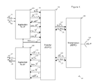
- FIG. 1 describes the architecture of a communication node 100 of a multi-stream audio distribution system, according to a particular embodiment of the invention.
- This node may behave both as a transmission device and as a reception device.
- each of the WAR and WAP nodes possesses, for example, the structure of the node 100 in Figure 1 . It is of course possible to plan for another implementation in which one or more of the WAR and WAP nodes (for example the WAP node) behave solely as a transmission device and one or more of the WAR and WAP nodes (for example the WAR nodes) behave solely as a reception device.
- Each communication node 100 can get connected to a source application (not shown) through a source applicative clock signal Sclk_in 105 and an applicative data signal Data_in 106 (this is the case, for example for the WAP).
- a transmission data-processing module 101 (Application Tx I/F) is responsible for retrieving the data coming from the source application, storing, it (writing it) to buffer memory and making it available in playback to the SDPC transfer mode management module 102 (also called the SDPC module).
- the transmission data-processing module 101 is also responsible for the computation and insertion of synchronization data pertaining to the invention.
- the exchange of synchronization data between the modules referenced 101 and 102 is done through interface signals Index_tx 112, Offset_tx 113 and Sync_tx 114.
- Each communications node 100 can also get connected to a destination application (not shown) through a consumer applicative clock signal Sclk_out 107 and an applicative data signal Data_out 108 (this is the case for example of a WAR).
- a reception data-processing module 104 (“Application Rx I/F") is responsible for retrieving the data from the virtual channels coming from the SDPC transfer mode management module 102 and storing it in a buffer memory so that it can be given to the destination application at the rate of Sclk_out.
- the exchange of synchronization data between the modules referenced 102 and 104 is done through interface signals Index_rx 117, Offset_rx 119 and Sync_rx 120.
- the SDPC module 102 is responsible, at each network cycle (TDM cycle) 118 for retrieving the content of the source applicative data and synchronization data to format the transmission-allocated virtual channels coming from the transmission data-processing module 101 and for transferring this information to a SDTC (Synchronous Data Transmission Cycle) transmission module 103.
- TDM cycle network cycle
- SDTC Synchronous Data Transmission Cycle
- the exchange of data between the modules referenced 102 and 103 is done through interface signals Data_tx 125 Ctrl_data_tx 121 in the direction of transmission to the network.
- the SDPC module 102 is responsible for retrieving the information coming from the transmission module 103 and, at each network cycle 118, for supplying the content of the reception-allocated virtual channels intended for the reception data-processing module 104.
- the exchange of data between the modules referenced 103 and 102 is done through interface signals Data_rx 122 and Ctrl_data_rx 123 in the sense of reception coming from the network.
- the transmission module 103 implements a synchronous transmission mode and uses a transmit/receive antenna 124 working in the 60 GHz frequency band.
- FIG. 2 describes the architecture of the transmission data-processing module 101 of Figure 1 according to a particular embodiment of the invention.
- This architecture consists of:
- the pieces of applicative data are stored in memory 200 at the rate of the write clock (source applicative clock signal Sclk_in 105) independently of the read operations performed by the SDPC module 102.
- the SDPC module 102 performs a predetermined number of read operations in the memory 200, computed as a function of the whole number of transmission-allocated virtual channels for said application and of the number of applicative data elements needed to fill a virtual channel. In the case of the multi-stream radio application considered, six read operations are therefore performed at each network cycle for each audio stream (i.e. for each stream of the eight-stream audio system).
- the virtual channels entirely filled with applicative data are formatted with a header indicating the presence of applicative data.
- the index computation module 201 Following a network cycle event (start of a network cycle), when the pieces of synchronization information (Index_tx 112 and Offset_tx 113) have to be inserted into a virtual channel allocated to the exchange of protocol information, the index computation module 201 generates an event on the signal Sync_tx 114. The SDPC module 102 will insert this information into a protocol type virtual channel during the next network cycle.
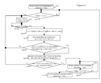
- Figure 3 provides a detailed description of the application of the operations of computation and insertion of synchronization information performed by the transmission data-processing module 101.
- the general principle consists in making an algorithm loop back at the rate of a predetermined adjustment period that is computed according to the requirements on the jitter and maximum frequency drift authorized by the application.
- the operation passes to a waiting step 301 and remains there until the detection of a need for generating new synchronization parameters (i.e. until detection of an adjustment event).
- the signal Sync_tx is set at zero by the index computation module 201 to inform the SDPC module 102 of the absence of synchronization information.
- the operation passes to the step 302 in which the signal Req 213 is activated for dispatch to the offset computation module 203. This corresponds to the sending of an offset computation request. Then, the operation passes to a waiting step 303 and remains there until detection of the signal Valid generated in return by the offset computation module 203.
- the offset computation module 203 Upon reception of the active signal Req 213, the offset computation module 203 is in effect responsible for computing a time offset or difference between the start of the current network cycle (cycle N) and the next event on the source applicative clock signal Sclk_in 105. The result obtained, expressed in number of events (or ticks) of the system clock 204 whose nominal value is predetermined within each node of the network is compared with a predetermined confidence interval.
- the lower and upper limits of this interval are fixed in taking account of the constraints of implementation of the device (time taken for computation and insertion in transmission, computation and adjustment time in reception).
- the computation is not validated and is done between the next event the source applicative clock signal Sclk_in 105 and the start of the current network cycle (cycle N).
- the signal Valid 212 is activated in return for dispatch to the index computation module 201 and the offset information is presented at the output signal Offset_tx 113.
- the request signal 213 is deactivated at the step 304 and the index information is set at the number of memory-resident application data 200. Then, in a step 305, the index value is decremented at the rate of the read events Rd_clk 111 of the module 102 until the detection of the next network cycle event 118 (start of the network cycle N +1).
- the signal Sync_tx is kept inactive so as to inhibit the request for transferring synchronization information in the network cycle N +1 and there is a returned to the step 302 in order to reiterate the computation process (computation offer time difference or offset between the start of the network cycle N and the next event on the source applicative clock signal Sclk_in 105).
- the signal Sync_tx is activated and the value of the index is copied to the output signal Index_tx 112 in order to insert the request to transfer synchronization information (Offset_tx and Index_tx) to the network cycle N +1.
- step 310 upon detection of the end of the network cycle N +1 (step 310), the request for transfer of the synchronization information is raised in the step 311 before returning to the waiting step 301 (pending a forthcoming adjustment event activating a new computation of synchronization information).
- This stream is either the single stream of the source application (the case of a single-stream source application) or one of the streams of the source application (the case of a multi-stream source application).
- This memory itself may be a memory zone of an overall memory common to several streams.
- the multi-stream source application If the multi-stream source application generates applicative data for each of the streams at the same rate, and if the transmission device writes simultaneously (at the rate of the source application clock) to the different buffers memories associated with the different streams, then it is enough to perform the computation and insertion of the synchronization information for only one of the streams.
- an eight-stream audio system comprising a WAP type node (associated with an multi-stream source application) and eight WAR type nodes (each associated with an destination application processing one stream)
- a WAP type node associated with an multi-stream source application
- eight WAR type nodes each associated with an destination application processing one stream
- the filling of the virtual channels of the network cycle for each of the streams is identical if the same number of virtual channels is allocated for each of the audio streams (i.e. if the application uses balanced streams).
- a stream is also called an audio channel.
- the synchronization information (offset and index information) for its part is computed only once for all the streams and is used in the same way at each of the destinations.
- one of the WAR type nodes namely the one that process the stream used in the transmission device to compute synchronization information applies the resetting on the sample (called a reference sample) that has effectively been used to compute this synchronization information.
- Each of the other WAR type nodes applies the resetting on a sample sent by the source application at the same time as the reference sample (i.e. during the same period 1/Fs).
- the method uses for example a single virtual channel of a control type to convey this information, each destination device being in a state of listening to this virtual control channel in order to apply the operations of adjusting the regenerated applicative clock.
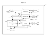
- FIG 4 describes the architecture of the reception data-processing module 104 of Figure 1 , according to a particular embodiment of the invention.
- This architecture consists of:
- the pieces of applications data coming from the interface Data_rx_VC 115 are stored in the memory 400 at the rate of the write clock Wr_clk 116 independently of the read operations for reading this memory at the rate of the signal Sclk_out 107.
- the SDPC module 102 performs a variable number of write operations to the memory 400, as a function of the headers of the applications type virtual channels retrieved from the transmission channel.
- the synchronization information (Offset and Index information) retrieved in a protocol type virtual channel is made available to the receive data processing module 104 through interface signals Index_rx 117 and Offset_rx 119 in activating the signal Sync_rx 120.
- the method for generating the applicative clock signal Sclk_out 107 consists on the whole in taking the output of the generator 403 by default and, upon detection of synchronization information, generating an event Adj 410 used as a signal Sclk_out 107 in place of the output signal of the module 403.
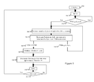
- Figure 5 is a flowchart of a method for receiving and using of the above-mentioned synchronized information (Offset and Index) according to one particular embodiment of the invention. This flowchart provides a detailed description of the implementation of the operations for readjusting the applicative clock Sclk_out 107 in the received data processing module 104.
- an event Adj 410 is generated at the end of a duration of a value equal to the information Offset_rx 119 coming from the SDPC module 102, the operation of counting this duration being initialized as of the next network cycle event (the start) that follows the detection of the active state of the signal Sync_rx 120.
- the signal Sel 405 is made inactive in a step 501.
- the signal Sclk_out 116 is connected to the output of the nominal frequency generator 403.
- the operation passes through a waiting step 502 in which the operation remains up to the detection of a network cycle event (start) 118 (also called a TDM cycle event).
- start also called a TDM cycle event
- an internal variable Position is assigned to the number of pieces of applicative data in the buffer memory 400 in the step 503, then decremented at the rate of the read operations by the clock Sclk_out 107 in the state 504 until detection of an event Sync_rx 120 or an network cycle event (start) 118.
- variable position is reinitialized at the sum of the preceding value plus the value of Index_rx 117 present at output of SDPC module 102 (step 507) then decremented at the rate of the read operations by the clock Sclk_out 107 until the reading of the piece of applicative data that precedes the piece of data that has to be resynchronized (reference data), i.e. until the variable Position reaches a zero value (step 508).
- the selection signal Sel 405 is set at 1 to link the signal Sclk_out 107 to the output Adj 410 of the counter 402. This is done until detection of the event Adj 410 (in the step 511).
- the event Adj 410 thus prompts the synchronization of the reading of the next piece of applicative data in the memory 400 with the information Offset_rx 119 relative to the temporal position of the start of the current network cycle. Then a loop is made to the step 501 in order to continue the generation of the signal Sclk_out 107 at the rate of its nominal frequency (output of the generator 403).
- temporal resetting of the instant reading of a particular piece of applicative data is performed independently of the jitter in the time taken to transmit this piece of data between the source node and the destination node.
- This approach using an index parameter independent of the position of this piece of data in the data frame associated with the network cycle and independent of the instant of writing of this piece of data in the network cycle, therefore has the advantage of overcoming the effects of the temporal characteristics associated with the formatting of the transfer mode. It also accepts a variable transmission time for the transmission of the synchronization information between applications.
- the proposed solution enables the synchronization on the fly of a received application in a multi-point scenario (either a new application or an application that is already one of the addressees but has been desynchronized and then resynchronized at the transmission mode level) since it is enough to inhibit the generation of the signal Sclk_out at output of the module 104 up to the first occurrence of the readjustment event Adj 410.
- the invention is not limited to a purely hardware layout but can also be implemented in the form of a sequence of computer program instructions or any form combining a hardware part and software part. Should the invention be embedded partially or totally in software form, the corresponding sequence of instructions could be stored in a storage means that is detachable (for example a floppy disk, a CD-ROM or DVD-ROM) or not detachable, this storage means being partially or totally readable by a computer or a microprocessor.
- a storage means that is detachable (for example a floppy disk, a CD-ROM or DVD-ROM) or not detachable, this storage means being partially or totally readable by a computer or a microprocessor.
Landscapes
- Engineering & Computer Science (AREA)
- Computer Networks & Wireless Communication (AREA)
- Signal Processing (AREA)
- Synchronisation In Digital Transmission Systems (AREA)
- Data Exchanges In Wide-Area Networks (AREA)
- Mobile Radio Communication Systems (AREA)
Abstract
Description
- The field of the invention is that of communication systems. More specifically, the invention relates to a technique of synchronization of applicative clock signals between a transmission device and at least one reception device connected to a synchronous communications network.
- A communication system consisting of terminals (also called devices or nodes) connected to a communications network is characterized:
- firstly, through the synchronous or asynchronous nature of the transmission mode used on the transmission channel and the mode of transfer of information above the transmission mode, and
- secondly through the synchronous or asynchronous nature of the applications borne within the terminals.
- Among the transmission modes implemented in networks, we can identify synchronous transmission modes (for example the ADSL or "Asymmetric Digital Subscriber Line") used in networks known as circuit-switching networks and asynchronous transmission modes (for example Ethernet) used in networks known as packet-switching networks.
- Among the transfer modes implemented in networks, we may cite TDM (Time Division Multiplexing) type synchronous transfer modes and asynchronous transfer modes using asynchronous data segmentation and reassembly techniques above the transmission channel (as used for example in the ATM Asynchronous Transfer Mode protocol).
- The classic and preferred way of supporting the implementation of synchronous applications (such as audio or video type applications) is to rely on a synchronous type network, at the level of both the transmission mode and the transfer mode. Indeed, the quality of service required for this type of application dictates a high level of temporal maintenance, at the level of the total system, between events created at the source and events regenerated at destination (in terms of tolerance with regard to transfer time between applications through the network, jitter at the time of delivery of applicative data, jitter at the time of delivery of data to two destination applications, for example).
- The setting up of synchronous applications in a multi-point scenario, implementing a synchronous data exchange between a source application and several destinations applications simultaneously (for example a Home Cinema type audio distribution application) dictates a quality of service due to human perception which entails very heavy constraints, firstly with regard to jitter at the instants of regeneration by the receiver applications of audio data for each audio stream (known as intra-stream jitter) and secondly at the instants of regeneration of data between audio streams (known as inter-stream jitter).
- In the case of an architecture where the transmit and receive applications use one and the same nominal reference frequency, there is by definition a variation between the two real frequencies due to tolerance as regards to the nominal frequency, generally expressed in ppm (parts per million) given by the electronic components. It is therefore necessary to use a technique to maintain synchronization between transmit and receive applications for this type of architecture, which strives to synchronize the clock of the consumer application with the clock of the sender application.
- Furthermore, in the implementation of a TDM type synchronous transfer mode, a time reference of fixed duration is defined. This time reference is called a network cycle or again a TDM cycle and distributed to all the nodes of the network. Another term used is "network clock" or again TDM clock corresponding to the network cycle. This network cycle is divided into a whole number of synchronous virtual channels (or VCs) designed to support the transmission of all the traffic between the nodes of the network. Each virtual channel is transmitted systematically at each network cycle and therefore represents a constant portion of the bandwidth of the transmission channel characterized by the fixed duration of the network cycle and by the fixed quantity of information contained in each virtual channel. The setting up of synchronous source and destination applications on this transfer mode then consists of the allocation to the source application (supported by a transmission node) of a constant whole number of virtual write channels as a function of the required applicative bandwidth, these same virtual channels being write-allocated for the destination application or applications (carried by reception nodes).
- Now, for most synchronous applications, the source applicative clock is independent of the network clock. Similarly, the format of the applicative data is generally independent of the format of the virtual channel data. In a network cycle, a virtual channel which cannot be entirely filled by applicative data will be formatted with a header indicating an absence of applicative data. A virtual channel entirely filled with applicative data will be formatted with a header indicating the presence of applicative data. Indeed, given the independence of the format between applicative data and virtual channel, the use of a complex virtual channel header to report the variable organization of the number of pieces of applicative data within a virtual channel would significantly reduce the useful bandwidth relative to the total bandwidth of the system. As a consequence, a piece of applicative data made available by the source application during a network cycle will not necessarily be transmitted via the network, in a virtual channel, during the next network cycle but could occasionally undergo a delay of one network cycle. The time taken to convey a piece of data between the instant of writing of this data (to a buffer memory included in the transmit node) by the source applicative clock and the instance of which this data is made available to the destination application is therefore variable in time within the network cycles.
- There are several known techniques in the prior art use to maintain synchronization between applications in an architecture in which sender and receiver applications use one and the same nominal reference frequency. Most of these known techniques focus on synchronizing the receiver (consumer) application clock with the sender application clock.
- In a first prior-art synchronization technique (described in "Understanding Jitter and Wander Measurements and Standards", Agilent Technologies, 5988-6254EN, 2003, especially Figure 12.5), the clocks continue to be used independently and there is no automatic control of frequency for the clocks. This first technique relies on the use of a method for the regulation of the throughput rate in the receiver node (called a slip buffer). It consists if the insertion or elimination of a piece of applicative data depending on the divergence in rhythm observed between the throughput rate of data coming from the network and the read rate by the receiver application. One drawback of this first technique is that it does not provide for the integrity of the data except when the precision in the nominal value of the clock frequencies is 0 ppm. If not, it is up to the receiver application to set up means to mask the defects of integrity of the data,
- A second prior-art synchronization technique (described in the
US patent 6,791,987 ), called adaptive memory or adaptive buffer consists in setting up an automatic control between the read frequency in the receive node as a function of the level of filling of a memory containing the applicative data coming from the communications network. This second known technique is used to accelerate the reading rate when the quantity of data in the reception memory goes beyond a predetermined threshold or to slow down the reading rate when the quantity of data in the reception memory falls below a predetermined threshold. However, one drawback of this second technique is that it necessitates the addition of developed smoothing methods in order to achieve the integration in time of measurements observed at specific times and thus prevent a jitter effect of the regenerated applicative frequency. Because of the compromise between the maximum time taken for the correction of a drift and the frequency precision with respect to the correction made, this type of method is ill suited to the quality of service requirements imposed on and expected from multipoint synchronous applications. - A third prior-art synchronization technique (described in the
US patent 6,327,273 ) makes direct use of the network cycle to generate the source and destination applicative clocks. In this case, each source and destination terminal multiplies its network cycle by a same value in order to generate its applicative clock. This third technique necessitates a mode of distribution of the network clock which sets up an automatic control between the network cycles at each terminal. One drawback of this third technique is that it cannot be used to support applicative clocks whose frequencies are independent (i.e. not a multiple or sub-multiple) of the clock frequency of the reference network. - A fourth prior art synchronization technique (described in the patent application
EP1052793A1 ) relies on the periodic dispatch by the source application of temporal information pertaining to time offsets between the events of the source applicative clock and events of the network clock. These pieces of temporal information or synchronous residual time stamps are intended for the computation at the sink node of a drift between source applicative clocks and destination applicative clocks through the network cycle and for setting up an automatic control accordingly between the destination applicative clock frequency and the source applicative frequency, depending on the content of the temporal information received. This fourth prior art technique dictates the setting up in the communications network of a service to ensure constant transfer time of this information, between the instant at which a piece of data is written by the source applicative clock and instant at which this piece of data is made available to the automatic control function of the destination applicative clock in the sink node. With regard to this constraint, this fourth technique can actually be used only in synchronous networks in which the nominal source clock of the application and the network reference clock have a relationship of proportionality between respective nominal values. - The invention in at least one embodiment is aimed especially of overcoming these different drawbacks of the prior art.
- More specifically, it is a goal of at least of one embodiment of the invention to provide a technique for the synchronizing of applications connected to a network using a TDM type synchronous transfer mode (with a network clock), the source and destination applicative clocks being independent of the network clock. In other words, it is a goal of the invention to provide a technique of synchronization of applicative clocks between a transmission device and at least one reception device connected to a synchronous communications network.
- At least one embodiment the invention is also aimed providing a technique of this kind that does not necessitate the setting up, in the communications network, of a service ensuring a constant data transfer time between the instant at which a piece of data is written by the source applicative clock and the instant of which this piece of data is made available to the automatic control function of the destination applicative clock in the sink node.
- It is an additional goal of at least one embodiment of the invention to provide a technique of this kind enabling synchronization on the fly of a new destination application in a multipoint applicative scenario.
- One particular embodiment of the present invention proposes a method for transmitting information enabling a synchronization of applicative clocks signals between an emitter device and at least one receiver device connected to a communications network, said emitter device performing the following steps:
- receiving pieces of applicative data from a source application, at a data rate defined by a source applicative clock, and
- transmitting said pieces of applicative data via said network, at a data rate defined by a network clock, the network clock being independent of the source applicative clock,
- determining a piece of time offset information between a reference instant of a current network cycle and an instant relative to the reception of a reference one of said pieces of applicative data;
- determining a piece of information on a position, of said reference piece of data, among the pieces of applicative data to be transmitted via said network during a determined network cycle;
- transmitting, via said network, said information on time offset and position during said determined network cycle.
- Another particular embodiment of the invention proposes a method for transmitting information for a synchronization of applicative clocks signals between an emitter device and at least one receiver device connected to a communications network implementing a time division multiplexing type of synchronous transfer mode with a network clock that defines a network cycle, said emitter device performing the following steps for each stream of a source application with at least one stream:
- writing to a buffer memory associated with said stream, at the rate of a source applicative clock, of pieces of applicative data of said stream coming from said source application, and
- transmitting, via said network, the pieces of applicative data of said stream at the rate of the network clock,
- determining a piece of time offset information between a starting instant of a current network cycle and an instant of writing one of the pieces of applicative data of said stream, called a reference piece of data, to the buffer memory associated with said stream;
- determining a piece of information on position of said reference piece of data from among the pieces of applicative data of said stream to be transmitted via said network during a determined network cycle;
- transmitting via the communications network of said information on time offset and position during said determined network cycle.
- Thus, the synchronization technique of the invention relies on an wholly novel and inventive approach in which it is not only a piece of time offset information that is transmitted (as in the above-mentioned fourth known technique) but also a piece of information on position of the data (called reference data) that has been used to compute the time offset information, and more generally a piece of information of the data (called reference data) that has been used to compute the time offset information.
- Thus (and as shall be shown in greater detail here below), the combined use of these two pieces of information makes it possible, in the reception device, to apply the time offset to the data used for its computation and thus enables the synchronizing in phase and frequency of remote applications (source and destination applications) whose data format and clocks are independent of the properties of the mode of transfer via the network (for example the format of the virtual channels and the network reference cycle). The above-mentioned fourth prior-art technique enables frequency synchronization but not phase synchronization, since no information about the reference piece of data is transmitted.
- The combined use of these two pieces of information also makes it possible, in each reception device, to carry out an on-the-fly synchronization of destination (or consumer) applications in the case of multipoint applicative systems. In this case, the data will be given to a consumer application only on the basis of the reference data received from the communications network in order to start the data transfer to the destination (or consumer) application with a consumer applicative clock locked in frequency and in phase with the source applicative clock.
- Advantageously, the determined network cycle is the network cycle following the current network cycle.
- Thus, the transmission latency in the communications network is reduced.
- Advantageously, said method comprises a step of checking that said reference piece of data will effectively be transmitted via the communications network during said determined network cycle and said step of transmission of said pieces of information on time offset and position is performed only if said reference piece of data is to be transmitted during the determined network cycle.
- Thus, it is possible to avoid conveying additional information representing the packetization jitter.
- According to an advantageous characteristic, said method comprises a step of comparison of said time offset information with a predetermined confidence interval, and said steps of determining a piece of information on position and of transmitting said pieces of information on time offset and position are performed only if said time offset information is included in said predetermined confidence interval.
- Thus, it is possible to allow an operational range of application of the time offset information in the receiver device as a function of the constraints of implementation related to the computation time required for the time offset information and by ensuring that the time offset will be smaller than the potential jitter of the network.
- Advantageously, each network cycle comprises an integer number of synchronous virtual channels. Said pieces of applicative data are transmitted in one or more of virtual data channels, allocated to the transmission of said applicative data. Said pieces of information on time offset and position are transmitted in at least one virtual control channel, distinct from said virtual data channels.
- Thus, the number and the position of the virtual channels used to convey the information on time offset and position information are independent of the number of channels allocated to the transmission of applicative data, thus regardless of the data applicative rate.
- According to one variant, each network cycle comprises an integer number of synchronous virtual channels, each virtual channel comprising a header and a payload part. The pieces of applicative data are transmitted in the payload part of one or more of said virtual channels. Said pieces of information on time offset and position are transmitted in the header of a virtual data and synchronization channel, the payload part of which contains said reference piece of data. If the payload part of said virtual data and synchronization channel contains only said reference piece of data, then said information on position is not transmitted in the header of said virtual data and synchronization channel.
- According to an advantageous characteristic, said method comprises a step of periodically generating said clock adjustment event, according to a predetermined period that is a function of requirements on the jitter and maximum frequency drift authorized by said source application generating said application data.
- Thus, the transmission of the information needed to ensure the synchronization of the emitter device and of the receiver device requires a small amount of bandwidth, in preventing transmission of this kind at each network cycle while at the same time ensuring compliance with application constraints.
- Advantageously, said source application generates at least two streams and generates applicative data at the same rate for each one of the streams. The steps of said method are performed only for one of said source application streams, said pieces of information on time offset and position being associated with a piece of data for each of the streams.
- Thus, in using pieces of information on time offset and position common to all the streams of a multi-stream application (as known as multi-channel application), the method requires no additional method of synchronization between receiver devices to comply with inter-stream synchronization (for example the spatial character of the rendering of a home cinema type sound amplifier system), and this is achieved independently of the location of the receiver devices in the synchronous network.
- Thus, it is enough to compute the pieces of information on time offset and position for a single stream since:
- the source application generates applicative data at the same rate for each of the streams;
- the source application provides simultaneously the piece of applicative data of said streams;
- the emitter device transmits the pieces of applicative data of the different streams simultaneously on said network, at the rate of the network clock.
- One of the receiver devices to which the first stream is intended applies the time offset to a reference piece of data of said first stream, which has been used to compute this time offset. Each other receiver device to which another stream is intended applies the time offset to a piece of data of this other stream generated (or provided) by the source application at the same time as the reference data for the first stream.
- In another embodiment, the invention proposes a method for receiving information enabling a synchronization of applicative clocks between an emitter device and at least one receiver device connected to a synchronous communications network, said receiver device performing the following steps:
- receiving pieces of applicative data via said network at a rate defined by a network clock, and
- providing said pieces of applicative data to a consumer application, at a rate defined by a consumer applicative clock, the consumer applicative clock being independent of the network clock,
- receiving, from the communications network, pieces of information on time offset and position associated with pieces of applicative data received during a network cycle;
- as a function of said information on position, selecting (507, 508) a reference piece of data from among the pieces of applicative data received from the communications network;
- determining an instant of providing said reference piece of data to said consumer application, starting from a starting instant of an offset applying network cycle (the network cycle during which the offset is applied) to which is added an offset defined by said piece of information on time offset;
- providing said reference piece of data at the determined instant, then providing the pieces of applicative data that follow said reference piece of data at the rate of said consumer applicative clock.
- Another embodiment of the invention relates to a method for receiving information enabling a synchronization of applicative clocks between an emitter device and at least one receiver device connected to a synchronous communications network, said communications network implementing a time division multiplexing type of synchronous transfer mode, with a network clock that defines a network cycle, said receiver device performing the following steps:
- writing, to a buffer memory, pieces of applicative data received via said network at the rate of the network clock, and
- reading, at the rate of a consumer applicative clock, pieces of applicative data stored in said memory, the data read being intended for a consumer application,
- receiving, from the communications network, pieces of information on time offset and position associated with pieces of applicative data received during a network cycle;
- as a function of said information on position, selecting a reference piece of data from among the pieces of applicative data written to the memory;
- determining an instant of reading said reference piece of data in said memory, starting from a starting instant of an offset applying network cycle (the network cycle during which the offset is applied) and adding an offset defined by said piece of temporal offset information;
- reading said reference piece of data at said reading instant, then reading the data that follows said reference piece of data at the rate of said consumer applicative clock.
- Advantageously, said piece of information on position is a piece of information on the position of said reference piece of data among the pieces of applicative data received from the communications network during the network cycle preceding said offset applying network cycle.
- Advantageously, the method comprises a step for invalidating the reading of applicative before said reference piece of data if a first iteration of the steps of said method has not already been performed or if a loss of synchronization has occurred since an already performed first iteration.
- This enables a synchronization of a destination (or consumer) application hosted by a receiver device, either in the event of a loss of synchronization or in the event of on-the-fly synchronization of a new destination (or consumer) application (such as a first connection of the receiver device that hosts it) in a multi-point applicative scenario.
- In another embodiment, the invention relates to a computer program product downloadable from a communications network and/or recorded on a computer-readable carrier and/or executable by a processor, said computer program product comprising program code instructions for the implementation of the method according to at least one of the above-mentioned embodiments when said program is executed on a computer.
- In another embodiment, the invention relates to a computer-readable storage means, possibly wholly or partially detachable, storing a set of instructions executable by said computer to implement the method according to at least one of the above-mentioned embodiments.
- Another embodiment of the invention proposes an emitter device transmitting information enabling a synchronization of applicative clocks signals between said emitter device and at least one receiver device connected to a communications network, said emitter device comprising:
- receiving means for receiving pieces of applicative data from a source application, at a data rate defined by a source applicative clock, and
- first transmitting means for transmitting via said network the pieces of applicative data at a rate defined by a network clock, the network clock being independent of the source applicative clock,
- means for determining a piece of time offset information between a reference instant of a current network cycle and an instant relative to the reception of a reference one of said pieces of applicative data;
- means for determining a piece of information on a position of said reference piece of data from among the pieces of applicative data to be transmitted via said network during a determined network cycle;
- second transmitting means for transmitting via the communications network said information on time offset and position during said determined network cycle.
- A particular embodiment of the invention proposes an emitter device transmitting information enabling a synchronization of applicative clocks signals between said emitter device and at least one receiver device connected to a communications network implementing a time division multiplexing type of synchronous transfer mode with a network clock that defines a network cycle, said transmission device comprising:
- writing means that can be used, for each stream of a source application with at least one stream, for the writing to a buffer memory associated with said stream, at the rate of a source applicative clock, of pieces of applicative data of said stream coming from said source application, and
- first transmission means enabling the transmission via said network, for each stream, of the pieces of applicative data of said stream at the rate of the network clock.
- Said transmission device comprises the following means activated for at least one stream of said source application, upon detection of a clock adjustment event:
- means for determining a piece of time offset information between a starting instant of a current network cycle and an instant of writing one of the pieces of applicative data of said stream, called a reference piece of data, to the buffer memory associated with said stream;
- means for determining a piece of information on position of said reference piece of data from among the pieces of applicative data of said stream to be transmitted via said network during a determined network cycle;
- second means for transmitting via the communications network said information on time offset and position during said determined network cycle.
- Advantageously, the determined network cycle is the network cycle following the current network cycle.
- Advantageously, said emitter device comprises means for checking that said reference piece of data will effectively be transmitted via the communications network during said determined network cycle and said second means for transmitting said pieces of information on time offset and position are activated only if said reference piece of data is to be transmitted during the determined network cycle.
- Advantageously, said transmission device comprises means for comparing said time offset information with a predetermined confidence interval, and said means for determining a piece of information on position and means for transmitting said pieces of information on time offset and position are activated only if said comparing means detect that said time offset information is included in said predetermined confidence interval.
- According to an advantageous variant, each network cycle comprises an integer number of synchronous virtual channels. Said first transmitting means transmit said pieces of applicative data of said stream in one or more virtual data channels of said virtual channels, assigned to the transmission of said applicative data. Said second transmitting means transmit said pieces of information on time offset and position in at least one virtual control channel, distinct from said virtual data channels.
- According to an advantageous variant, each network cycle comprises an integer number of synchronous virtual channels, each virtual channel comprising a header and a payload part. Said first transmitting means transmit the pieces of applicative data in the payload part of one or more of said virtual channels. Said second transmitting means transmit said pieces of information on time offset and position in the header of a virtual data and synchronization channel, the payload part of which contains said reference piece of data. If the payload part of said virtual data and synchronization channel contains only said reference piece of data, then said second transmitting means do not transmit said information on position in the header of said virtual data and synchronization channel.
- Advantageously, said transmission device comprises means for periodically generating said clock adjustment event, according to a predetermined period as a function of requirements on the jitter and maximum frequency drift authorized by said source application generating said applicative data.
- Advantageously, said source application generates (or provides) at least two streams and generates applicative data at the same rate for each of the streams. The means of said emitter device are activated only for one of said source application streams, said pieces of information on time offset and position being associated with a piece of data for each of the streams.
- In another embodiment, the invention relates to a receiver device receiving information enabling a synchronization of applicative clocks between an emitter device and at least one receiver device connected to a synchronous communications network, said receiver device comprising:
- receiving means for receiving pieces of applicative data from said network at a rate defined by a network clock, and
- providing means for providing said pieces of applicative data to a consumer application, at a rate defined by a consumer applicative clock, the consumer applicative clock being independent of the network clock,
- receiving means for receiving from the communications network pieces of information on time offset and position associated with pieces of applicative data received during a network cycle;
- selecting means for selecting, as a function of said information on position, of a reference piece of data from among the pieces of applicative data received from the communications network;
- determining means for determining an instant of providing said reference piece of data, starting from a reference instant of an offset applying network cycle (the network cycle during which the offset is applied) to which is added an offset defined by said information on time offset;
- providing means for providing said reference piece of data at said determined instant, and of providing the pieces of applicative data that follows said reference piece of data at the rate of said consumer applicative clock.
- In another embodiment, the invention relates to a receiver device receiving information enabling a synchronization of applicative clocks between an emitter device and at least one receiver device connected to a synchronous communications network, said communications network implementing a time division multiplexing type of synchronous transfer mode, with a network clock that defines a network cycle, said reception device comprises:
- writing means enabling the writing, to a buffer memory, of pieces of applicative data received on said network at the rate of the network clock, and
- reading means enabling the reading, at the rate of a consumer applicative clock, of pieces of applicative data stored in said memory, the data read being intended for a consumer application.
- Said receiver device comprises the following means activated at least once:
- receiving means for receiving, from the communications network, pieces of information on time offset and position associated with pieces of applicative data received during a network cycle;
- selecting means for selecting, as a function of said information on position, of a reference piece of data from among the pieces of applicative data written to the memory;
- determining means for determining of an instant of reading of said reference piece of data in said memory, starting from a starting instant of a network cycle, called an offset applying network cycle (the network cycle during which the offset is applied), in adding an offset defined by said piece of temporal offset information;
- reading means for reading said reference piece of data at said reading instant, and then the applicative data that follows said reference piece of data at the rate of said consumer applicative clock.
- Advantageously, said piece of information on position is a piece of information on the position of said reference piece of data among the pieces of applicative data received from the communications network during the network cycle preceding said offset applying network cycle.
- Advantageously, said receiver device comprises invalidating means for invalidating the reading of applicative data received before said reference piece of data if a first activation of the means of said device has not already been performed or if a loss of synchronization has occurred since an already performed first activation.
- Other features and advantages of embodiments of the invention shall appear from the following description, given by way of an indicative and non-exhaustive example (not all the embodiments of the invention are limited to the characteristics and advantages of the embodiments described here below), and from the appended drawings, of which:
-
Figure 1 describes the architecture of a communication node (which may be considered to be a transmission device and a reception device) of a multi-stream audio distribution system, according to a particular embodiment of the invention; -
Figure 2 describes the architecture of the transmission data-processing module connected to a source application and seen inFigure 1 , according to a particular embodiment of the invention; -
Figure 3 is a flowchart of a method for computing and transmitting synchronization information according to a particular embodiment of the invention; -
Figure 4 describes the architecture of the reception data-processing module connected to a receiver application and seen inFigure 1 , according to a particular embodiment of the invention; and -
Figure 5 is a flowchart of a method for the reception and use of synchronization information according to a particular embodiment of the invention. - In all the figures of the present document, the identical elements and steps are designated by identical numerical references.
- Purely by way of illustration, an example is presented here below in the description of an application of the invention to an eight-stream audio system, working at 60GHz and consisting of nine transmission nodes.
- More particularly, the system comprises:
- Eight WAR (Wireless Audio Renderer) type nodes, each of which is fitted out with an audio stream renderer integrating especially a speaker, and
- A WAP (Wireless Audio Player) type node, equipped with a multi-stream audio decoder or surround sound decoder capable of transmitting of all the different audio streams coming from a same source through the 60GHz communications network formed by the set of WAR and WAP nodes,
- An audio stream having a resolution of 44.1KHz-24bits will therefore use three virtual channels, by virtue of a theoretical computation of 2.756, giving for example for a full eight-channel system, conventionally called a 7.1 system, a total of 24 virtual channels, giving a necessary payload throughput rate of 9.216 Mbps (megabits per second) for the transfer of audio information. If, for the transfer of additional information in synchronous mode (control of the system, protocol, user control, etc), we add a virtual channel allocated to each transmission node of the system, a network cycle consists of 33 virtual channels, giving a payload throughput rate of 12.672 Mbps.
-
Figure 1 describes the architecture of acommunication node 100 of a multi-stream audio distribution system, according to a particular embodiment of the invention. This node may behave both as a transmission device and as a reception device. In the above-mentioned example, each of the WAR and WAP nodes possesses, for example, the structure of thenode 100 inFigure 1 . It is of course possible to plan for another implementation in which one or more of the WAR and WAP nodes (for example the WAP node) behave solely as a transmission device and one or more of the WAR and WAP nodes (for example the WAR nodes) behave solely as a reception device. - Each
communication node 100 can get connected to a source application (not shown) through a source applicativeclock signal Sclk_in 105 and an applicative data signal Data_in 106 (this is the case, for example for the WAP). - A transmission data-processing module 101 (Application Tx I/F) is responsible for retrieving the data coming from the source application, storing, it (writing it) to buffer memory and making it available in playback to the SDPC transfer mode management module 102 (also called the SDPC module).
- In the case of a multi-stream source application, there is one memory per stream, this memory itself being possibly a memory zone of a total memory common to several streams.
- The transmission data-
processing module 101 is also responsible for the computation and insertion of synchronization data pertaining to the invention. - The exchange of applicative data between the modules referenced 101 and 102 is done through interface signals
Data_tx_VC 110,Rd_clk 111 and Empty 109. - The exchange of synchronization data between the modules referenced 101 and 102 is done through interface signals
Index_tx 112,Offset_tx 113 andSync_tx 114. - Each
communications node 100 can also get connected to a destination application (not shown) through a consumer applicativeclock signal Sclk_out 107 and an applicative data signal Data_out 108 (this is the case for example of a WAR). - A reception data-processing module 104 ("Application Rx I/F") is responsible for retrieving the data from the virtual channels coming from the SDPC transfer
mode management module 102 and storing it in a buffer memory so that it can be given to the destination application at the rate of Sclk_out. - The exchange of applicative data between the modules referenced 102 and 104 is done through interface signals
Data_rx_VC 115 andWr_clk 116. - The exchange of synchronization data between the modules referenced 102 and 104 is done through interface signals
Index_rx 117,Offset_rx 119 andSync_rx 120. - The
SDPC module 102 is responsible, at each network cycle (TDM cycle) 118 for retrieving the content of the source applicative data and synchronization data to format the transmission-allocated virtual channels coming from the transmission data-processing module 101 and for transferring this information to a SDTC (Synchronous Data Transmission Cycle)transmission module 103. The exchange of data between the modules referenced 102 and 103 is done through interface signals Data_tx 125Ctrl_data_tx 121 in the direction of transmission to the network. - The
SDPC module 102 is responsible for retrieving the information coming from thetransmission module 103 and, at eachnetwork cycle 118, for supplying the content of the reception-allocated virtual channels intended for the reception data-processing module 104. - The exchange of data between the modules referenced 103 and 102 is done through interface signals
Data_rx 122 andCtrl_data_rx 123 in the sense of reception coming from the network. - The
transmission module 103 implements a synchronous transmission mode and uses a transmit/receiveantenna 124 working in the 60 GHz frequency band. -
Figure 2 describes the architecture of the transmission data-processing module 101 ofFigure 1 according to a particular embodiment of the invention. This architecture consists of: - a
buffer memory 200 connected to the source application; - an offset
computation module 203; - an
index computation module 201, and - a system (quartz)
clock 204. - The pieces of applicative data (applicative data signal Data_in 106) are stored in
memory 200 at the rate of the write clock (source applicative clock signal Sclk_in 105) independently of the read operations performed by theSDPC module 102. - At each
network cycle 118, theSDPC module 102 performs a predetermined number of read operations in thememory 200, computed as a function of the whole number of transmission-allocated virtual channels for said application and of the number of applicative data elements needed to fill a virtual channel. In the case of the multi-stream radio application considered, six read operations are therefore performed at each network cycle for each audio stream (i.e. for each stream of the eight-stream audio system). - When a 48-bit virtual channel cannot be filled entirely by two 24-bit audio samples, which happens occasionally for the last virtual channel allocated per audio stream, this virtual channel will be formatted with a header indicating the absence of applicative data, and the writing to the virtual channel of the audio sample already read will take place in the first virtual channel allocated to the audio stream during the next network cycle.
- The virtual channels entirely filled with applicative data are formatted with a header indicating the presence of applicative data.
- Following a network cycle event (start of a network cycle), when the pieces of synchronization information (
Index_tx 112 and Offset_tx 113) have to be inserted into a virtual channel allocated to the exchange of protocol information, theindex computation module 201 generates an event on thesignal Sync_tx 114. TheSDPC module 102 will insert this information into a protocol type virtual channel during the next network cycle. -
Figure 3 provides a detailed description of the application of the operations of computation and insertion of synchronization information performed by the transmission data-processing module 101. - The general principle consists in making an algorithm loop back at the rate of a predetermined adjustment period that is computed according to the requirements on the jitter and maximum frequency drift authorized by the application.
- After an
initialization step 300, the operation passes to a waitingstep 301 and remains there until the detection of a need for generating new synchronization parameters (i.e. until detection of an adjustment event). During thestep 300, the signal Sync_tx is set at zero by theindex computation module 201 to inform theSDPC module 102 of the absence of synchronization information. - Following the detection of an adjustment event, the operation passes to the
step 302 in which the signal Req 213 is activated for dispatch to the offsetcomputation module 203. This corresponds to the sending of an offset computation request. Then, the operation passes to a waitingstep 303 and remains there until detection of the signal Valid generated in return by the offsetcomputation module 203. Upon reception of the active signal Req 213, the offsetcomputation module 203 is in effect responsible for computing a time offset or difference between the start of the current network cycle (cycle N) and the next event on the source applicativeclock signal Sclk_in 105. The result obtained, expressed in number of events (or ticks) of thesystem clock 204 whose nominal value is predetermined within each node of the network is compared with a predetermined confidence interval. The lower and upper limits of this interval are fixed in taking account of the constraints of implementation of the device (time taken for computation and insertion in transmission, computation and adjustment time in reception). Thus, when the result is beyond the fixed the confidence slot, the computation is not validated and is done between the next event the source applicativeclock signal Sclk_in 105 and the start of the current network cycle (cycle N). When a result meets the confidence criteria, the signal Valid 212 is activated in return for dispatch to theindex computation module 201 and the offset information is presented at theoutput signal Offset_tx 113. - Upon detection of the signal Valid 212, the request signal 213 is deactivated at the
step 304 and the index information is set at the number of memory-resident application data 200. Then, in astep 305, the index value is decremented at the rate of the readevents Rd_clk 111 of themodule 102 until the detection of the next network cycle event 118 (start of the network cycle N +1). - Upon detection of the start of a network cycle N +1, the tests of the steps 306 to 308 performed in order to ascertain that the applicative data in
memory 200 associated with the value of the index (at the time of the start of the network cycle N +1) will be transmitted in the network cycle N +1 that has just started. This computation comes directly from the commentary ofFigure 2 relating to the independence of format between applicative data and virtual channel and, in the case of the audio application described, will occur occasionally for an audio sample that has to be written to the third virtual channel. - More specifically, in the step 306, a check is made to see whether the memory size available in the virtual channels allocated to the application is greater then the memory size needed to convey the x (where x = "index") first pieces of data in memory. If the answer is affirmative at the step 306, the operation passes to the
step 307 in which the position of the indexth (or xth) piece of data in memory in the virtual channels allocated to the application is computed. Then, at thestep 308, a check is made to see whether the indexth (or xth) piece of data in memory is situated in an entirely filled virtual channel. If the answer is affirmative then, at thestep 308, the operation passes to thestep 309. - If the answer is negative then, at the step 306 or at the step 308 (i.e. should the computations show that the applicative data concerned is not transmitted in the network cycle N +1), the signal Sync_tx is kept inactive so as to inhibit the request for transferring synchronization information in the network cycle N +1 and there is a returned to the
step 302 in order to reiterate the computation process (computation offer time difference or offset between the start of the network cycle N and the next event on the source applicative clock signal Sclk_in 105). - At the step 309 (performed if the applicative data concerned is transmitted in the network cycle N +1), the signal Sync_tx is activated and the value of the index is copied to the
output signal Index_tx 112 in order to insert the request to transfer synchronization information (Offset_tx and Index_tx) to the network cycle N +1. - Then, upon detection of the end of the network cycle N +1 (step 310), the request for transfer of the synchronization information is raised in the
step 311 before returning to the waiting step 301 (pending a forthcoming adjustment event activating a new computation of synchronization information). - It must be noted that, for the sake of simplicity, the following description of
Figures 2 and3 presents the computation and the insertion of synchronization information performed for one stream of the source application. This stream is either the single stream of the source application (the case of a single-stream source application) or one of the streams of the source application (the case of a multi-stream source application). - As shown here above, in the case of a multi-stream source application, there is one memory per stream. This memory itself may be a memory zone of an overall memory common to several streams.
- If the multi-stream source application generates applicative data for each of the streams at the same rate, and if the transmission device writes simultaneously (at the rate of the source application clock) to the different buffers memories associated with the different streams, then it is enough to perform the computation and insertion of the synchronization information for only one of the streams.
- Thus, in the above mentioned case of an eight-stream audio system comprising a WAP type node (associated with an multi-stream source application) and eight WAR type nodes (each associated with an destination application processing one stream), if all the audio samples are sent simultaneously for all the streams, at the frequency Fs by the source application, then the filling of the virtual channels of the network cycle for each of the streams is identical if the same number of virtual channels is allocated for each of the audio streams (i.e. if the application uses balanced streams). A stream is also called an audio channel.
- The synchronization information (offset and index information) for its part is computed only once for all the streams and is used in the same way at each of the destinations. In the above-mentioned case of an eight-stream audio system, one of the WAR type nodes, namely the one that process the stream used in the transmission device to compute synchronization information applies the resetting on the sample (called a reference sample) that has effectively been used to compute this synchronization information. Each of the other WAR type nodes applies the resetting on a sample sent by the source application at the same time as the reference sample (i.e. during the
same period 1/Fs). - The method uses for example a single virtual channel of a control type to convey this information, each destination device being in a state of listening to this virtual control channel in order to apply the operations of adjusting the regenerated applicative clock.
-
Figure 4 describes the architecture of the reception data-processing module 104 ofFigure 1 , according to a particular embodiment of the invention. This architecture consists of: - A
buffer memory 400 connected to the destination application; - A read clock selection module 401 (consumer applicative clock signal Sclk_out 107);
- A counter 402;
- A nominal read
clock generator Sclk_out 403, based on a sub-multiple of thesystem clock 204; - A multiplexer 404; and
- The
system clock 204. - The pieces of applications data coming from the
interface Data_rx_VC 115 are stored in thememory 400 at the rate of thewrite clock Wr_clk 116 independently of the read operations for reading this memory at the rate of thesignal Sclk_out 107. - At each
network cycle 118, theSDPC module 102 performs a variable number of write operations to thememory 400, as a function of the headers of the applications type virtual channels retrieved from the transmission channel. - In a network cycle, the synchronization information (Offset and Index information) retrieved in a protocol type virtual channel is made available to the receive
data processing module 104 through interface signalsIndex_rx 117 andOffset_rx 119 in activating thesignal Sync_rx 120. - The method for generating the applicative
clock signal Sclk_out 107 consists on the whole in taking the output of thegenerator 403 by default and, upon detection of synchronization information, generating anevent Adj 410 used as asignal Sclk_out 107 in place of the output signal of themodule 403. -
Figure 5 is a flowchart of a method for receiving and using of the above-mentioned synchronized information (Offset and Index) according to one particular embodiment of the invention. This flowchart provides a detailed description of the implementation of the operations for readjusting theapplicative clock Sclk_out 107 in the receiveddata processing module 104. - According to the principle of operation of the counter 402, an
event Adj 410 is generated at the end of a duration of a value equal to theinformation Offset_rx 119 coming from theSDPC module 102, the operation of counting this duration being initialized as of the next network cycle event (the start) that follows the detection of the active state of thesignal Sync_rx 120. - After a
initialization step 500, thesignal Sel 405 is made inactive in astep 501. Thus, thesignal Sclk_out 116 is connected to the output of thenominal frequency generator 403. - Then, the operation passes through a waiting
step 502 in which the operation remains up to the detection of a network cycle event (start) 118 (also called a TDM cycle event). - Upon detection of a network cycle event (start), an internal variable Position is assigned to the number of pieces of applicative data in the
buffer memory 400 in thestep 503, then decremented at the rate of the read operations by theclock Sclk_out 107 in the state 504 until detection of anevent Sync_rx 120 or an network cycle event (start) 118. - Upon detection (506) of an network cycle event (start) 118, there is a return to the
step 503 so as to reiterate the initialization of the variable Position at the number of pieces of applicative data in thememory 400. - Upon detection (505) of the event Sync_rx, the variable position is reinitialized at the sum of the preceding value plus the value of
Index_rx 117 present at output of SDPC module 102 (step 507) then decremented at the rate of the read operations by theclock Sclk_out 107 until the reading of the piece of applicative data that precedes the piece of data that has to be resynchronized (reference data), i.e. until the variable Position reaches a zero value (step 508). - At this point in time, in the
step 510, theselection signal Sel 405 is set at 1 to link thesignal Sclk_out 107 to theoutput Adj 410 of the counter 402. This is done until detection of the event Adj 410 (in the step 511). - The
event Adj 410 thus prompts the synchronization of the reading of the next piece of applicative data in thememory 400 with theinformation Offset_rx 119 relative to the temporal position of the start of the current network cycle. Then a loop is made to thestep 501 in order to continue the generation of thesignal Sclk_out 107 at the rate of its nominal frequency (output of the generator 403). - Thus, the temporal resetting of the instant reading of a particular piece of applicative data (reference data) is performed independently of the jitter in the time taken to transmit this piece of data between the source node and the destination node.
- This approach, using an index parameter independent of the position of this piece of data in the data frame associated with the network cycle and independent of the instant of writing of this piece of data in the network cycle, therefore has the advantage of overcoming the effects of the temporal characteristics associated with the formatting of the transfer mode. It also accepts a variable transmission time for the transmission of the synchronization information between applications.
- Advantageously, the proposed solution enables the synchronization on the fly of a received application in a multi-point scenario (either a new application or an application that is already one of the addressees but has been desynchronized and then resynchronized at the transmission mode level) since it is enough to inhibit the generation of the signal Sclk_out at output of the
module 104 up to the first occurrence of thereadjustment event Adj 410. - It will be noted that the invention is not limited to a purely hardware layout but can also be implemented in the form of a sequence of computer program instructions or any form combining a hardware part and software part. Should the invention be embedded partially or totally in software form, the corresponding sequence of instructions could be stored in a storage means that is detachable (for example a floppy disk, a CD-ROM or DVD-ROM) or not detachable, this storage means being partially or totally readable by a computer or a microprocessor.
Claims (15)
- Method for transmitting information enabling a synchronization of applicative clocks signals between an emitter device and at least one receiver device connected to a communications network, said emitter device performing the following steps:- receiving pieces of applicative data from a source application, at a data rate defined by a source applicative clock, and- transmitting said pieces of applicative data via said network, at a data rate defined by a network clock, the network clock being independent of the source applicative clock;,characterized in that said emitter device performs the following steps upon detection of a clock adjustment event:- determining (302, 303) a piece of time offset information (Offset_tx) between a reference instant of a current network cycle and an instant relative to the reception of a reference one of said pieces of applicative data;- determining (304, 305) a piece of information (Index_tx) on a position, of said reference piece of data, among the pieces of applicative data to be transmitted via said network during a determined network cycle;- transmitting (309), via said network, said information on time offset and position during said determined network cycle.
- Method according to claim 1, characterized in that the determined network cycle is the network cycle following the current network cycle.
- Method according to any one of the claims 1 and 2, characterized in that it comprises a step of checking (306 to 308) that said reference piece of data will effectively be transmitted via the network during said determined network cycle and in that said step of transmitting said pieces of information on time offset and position is performed only if said reference piece of data is to be transmitted during the determined network cycle.
- Method according to any one of the claims 1 to 3, characterized in that it comprises a step of comparing said time offset information with a predetermined confidence interval, and in that said steps of determining a piece of information on position and of transmitting said pieces of information on time offset and position are performed only if said time offset information is included in said predetermined confidence interval.
- Method according to any one of the claims 1 to 4, characterized in that each network cycle comprises an integer number of synchronous virtual channels,in that said pieces of applicative data are transmitted in one or more virtual data channels of said virtual channels, allocated to the transmission of said applicative data,and in that said pieces of information on time offset and position are transmitted in at least one virtual control channel of said virtual channels, distinct from said virtual data channels.
- Method according to any one of the claims 1 to 4, characterized in that each network cycle comprises an integer number of synchronous virtual channels, each virtual channel comprising a header part and a payload part,in that the pieces of applicative data are transmitted in the payload part of one or more of said virtual channels,in that said pieces of information on time offset and position are transmitted in the header of a virtual data and synchronization channel, the payload part of which contains said reference piece of data,and in that, if the payload part of said virtual data and synchronization channel contains only said reference piece of data, then said information on position is not transmitted in the header of said virtual data and synchronization channel.
- Method according to any one of the claims 1 to 6, characterized in that it comprises a step of periodic generation of said clock adjustment event, according to a predetermined period that is a function of requirements on the jitter and maximum frequency drift authorized by said source application generating said application data.
- Method according to any one of the claims 1 to 7, characterized in that said source application generates at least two streams and generates applicative data at the same rate for each of the streams,
and in that the steps of said method are performed only for one of said source application streams, said pieces of information on time offset and position being associated with a piece of data for each of the streams. - Method for receiving information enabling a synchronization of applicative clocks between an emitter device and at least one receiver device connected to a synchronous communications network, said receiver device performing the following steps:- receiving pieces of applicative data via said network at a rate defined by a network clock, and- providing said pieces of applicative data to a consumer application, at a rate defined by a consumer applicative clock, the consumer applicative clock being independent of the network clock,said method being characterized in that the receiver device performs at least one iteration of the following steps:- receiving, from the communications network, pieces of information on time offset (Offset_rx) and position (Index_rx) associated with pieces of applicative data received during a network cycle;- as a function of said information on position, selecting (507, 508) a reference piece of data from among the pieces of applicative data received from the communications network;- determining an instant of providing said reference piece of data to said consumer application, starting from a starting instant of an offset applying network cycle to which is added an offset defined by said piece of information on time offset;- providing said reference piece of data at the determined instant, then providing the pieces of applicative data that follow said reference piece of data at the rate of said consumer applicative clock.
- Method according to claim 9, characterized in that said piece of information on position is a piece of information on the position of said reference piece of data among the pieces of applicative data received from the communications network during the network cycle preceding said offset applying network cycle.
- Method according to any one of the claims 9 and 10, characterized in that it comprises a step of invalidating pieces of applicative data received before said reference piece of data if a first iteration of the steps of said method has not already been performed or if a loss of synchronization has occurred since an already performed first iteration.
- Computer program product downloadable from a communications network and/or recorded on a computer-readable carrier and/or executable by a processor, said computer program product comprising program code instructions for an implementation of the method according to at least one of the claims 1 to 11, when said program is executed on a computer.
- Computer-readable storage means storing a set of instructions executable by said computer to implement the method according to at least one of the claims 1 to 11.
- Emitter device transmitting information enabling a synchronization of applicative clocks signals between said emitter device and at least one receiver device connected to a communications network, said emitter device comprising:- receiving means for receiving pieces of applicative data from a source application, at a data rate defined by a source applicative clock, and- first transmitting means for transmitting via said network the pieces of applicative data at a rate defined by a network clock, the network clock being independent of the source applicative clock,said emitter device being characterized in that it comprises the following means, activated upon detection of a clock adjustment event:- means for determining a piece of time offset information between a reference instant of a current network cycle and an instant relative to the reception of a reference one of said pieces of applicative data;- means for determining a piece of information on a position of said reference piece of data from among the pieces of applicative data to be transmitted via said network during a determined network cycle;- second transmitting means for transmitting via the communications network said information on time offset and position during said determined network cycle.
- Receiver device receiving information enabling a synchronization of applicative clocks between an emitter device and at least one receiver device connected to a synchronous communications network, said receiver device comprising:- receiving means for receiving pieces of applicative data from said network at a rate defined by a network clock, and- providing means for providing said pieces of applicative data to a consumer application, at a rate defined by a consumer applicative clock, the consumer applicative clock being independent of the network clock,said receiver device being characterized in that it comprises the following means activated at least once:- receiving means for receiving from the communications network pieces of information on time offset and position associated with pieces of applicative data received during a network cycle;- selecting means for selecting, as a function of said information on position, of a reference piece of data from among the pieces of applicative data received from the communications network;- determining means for determining an instant of providing said reference piece of data, starting from a reference instant of an offset applying network cycle to which is added an offset defined by said information on time offset;- providing means for providing said reference piece of data at said determined instant, and of providing the pieces of applicative data that follows said reference piece of data at the rate of said consumer applicative clock.
Applications Claiming Priority (1)
| Application Number | Priority Date | Filing Date | Title |
|---|---|---|---|
| FR0850441A FR2926937A1 (en) | 2008-01-24 | 2008-01-24 | METHODS FOR SYNCHRONIZING APPLICATION TIMES IN A SYNCHRONOUS COMMUNICATION NETWORK, TRANSMITTING AND RECEIVING DEVICES, COMPUTER PROGRAM PRODUCT, AND CORRESPONDING STORAGE MEDIUM. |
Publications (2)
| Publication Number | Publication Date |
|---|---|
| EP2083526A1 true EP2083526A1 (en) | 2009-07-29 |
| EP2083526B1 EP2083526B1 (en) | 2011-03-09 |
Family
ID=39679296
Family Applications (1)
| Application Number | Title | Priority Date | Filing Date |
|---|---|---|---|
| EP09150203A Not-in-force EP2083526B1 (en) | 2008-01-24 | 2009-01-08 | Method for synchronizing applicative clock signals in a synchronous communications network, corresponding emitter and receiver devices, computer program product and computer-readable storage means. |
Country Status (5)
| Country | Link |
|---|---|
| US (1) | US8243727B2 (en) |
| EP (1) | EP2083526B1 (en) |
| AT (1) | ATE501558T1 (en) |
| DE (1) | DE602009000810D1 (en) |
| FR (1) | FR2926937A1 (en) |
Cited By (2)
| Publication number | Priority date | Publication date | Assignee | Title |
|---|---|---|---|---|
| FR2940873A1 (en) * | 2009-01-07 | 2010-07-09 | Canon Kk | Method for synchronizing transmission of application data frames between emission device and receiving device via synchronous communication network, involves transmitting treated application data to counter of predetermined network cycle |
| FR2940874A1 (en) * | 2009-01-07 | 2010-07-09 | Canon Kk | Method for synchronizing transmission of application data frames between emission device and receiving device via synchronous communication network, involves transmitting treated application data to counter of predetermined network cycle |
Families Citing this family (4)
| Publication number | Priority date | Publication date | Assignee | Title |
|---|---|---|---|---|
| US8369354B2 (en) * | 2009-01-07 | 2013-02-05 | Canon Kabushiki Kaisha | Method for synchronizing a transmission of applications data frames, corresponding sender and receiver devices and storage means |
| KR101295159B1 (en) | 2012-03-20 | 2013-08-09 | 성균관대학교산학협력단 | Method of timing offset detection for initial ranging process of fixed wireless communication system and apparatus for performing the same |
| US11641245B2 (en) * | 2021-05-03 | 2023-05-02 | Mellanox Technologies, Ltd. | Timestamp confidence level |
| US11606157B1 (en) | 2021-11-07 | 2023-03-14 | Mellanox Technologies, Ltd. | Time synchronization based on network traffic patterns |
Citations (5)
| Publication number | Priority date | Publication date | Assignee | Title |
|---|---|---|---|---|
| FR2693864A1 (en) * | 1992-07-17 | 1994-01-21 | Thomson Csf | Synchronisation of decoder connected to asynchronous transmission network audio-video services - controlling flow of data from coder to decoder w.r.t. relative capacities and occupation levels of respective buffers |
| EP0939507A1 (en) * | 1998-02-25 | 1999-09-01 | Koninklijke Philips Electronics N.V. | Interactive system for the ditribution of numeric audiovisual signals |
| EP1052793A1 (en) | 1999-05-11 | 2000-11-15 | Canon Kabushiki Kaisha | Method and device for the synchronisation between two networks |
| US6327273B1 (en) | 1996-11-08 | 2001-12-04 | Alcatel | Method to transparently transport an incoming clock signal over a network segment, and related transmitter and receiver unit |
| US6791987B1 (en) | 1998-10-23 | 2004-09-14 | Nortel Networks Limited | Maintaining synchronization over asynchronous interface |
Family Cites Families (13)
| Publication number | Priority date | Publication date | Assignee | Title |
|---|---|---|---|---|
| GB2272610B (en) * | 1992-11-12 | 1996-10-09 | Northern Telecom Ltd | Telecommunications systems |
| JP3161911B2 (en) * | 1994-08-03 | 2001-04-25 | 富士通株式会社 | Line switching method and line switching device |
| US6128318A (en) * | 1998-01-23 | 2000-10-03 | Philips Electronics North America Corporation | Method for synchronizing a cycle master node to a cycle slave node using synchronization information from an external network or sub-network which is supplied to the cycle slave node |
| US6050595A (en) | 1998-02-19 | 2000-04-18 | Textron Automotive Company Inc. | Peel back method and apparatus for deployably concealing an air bag behind an instrument panel |
| US6324172B1 (en) * | 1999-03-08 | 2001-11-27 | Qualcomm Incorporated | Method of rate allocation in a data communications network |
| EP1198085B1 (en) * | 2000-10-10 | 2011-06-08 | Sony Deutschland GmbH | Cycle synchronization between interconnected sub-networks |
| FR2820921A1 (en) * | 2001-02-14 | 2002-08-16 | Canon Kk | DEVICE AND METHOD FOR TRANSMISSION IN A SWITCH |
| DE10113260B4 (en) * | 2001-03-16 | 2005-10-20 | Siemens Ag | Synchronous, clocked communication system with relative clock and method for constructing such a system |
| JP2002344350A (en) * | 2001-05-17 | 2002-11-29 | Mitsubishi Electric Corp | Spread spectrum transmitter, spread spectrum receiver, and spread spectrum communication system |
| JP2003244085A (en) * | 2002-02-19 | 2003-08-29 | Fujitsu Ltd | Phase matching control system and phase matching control method in multiple transmission lines |
| US20060286975A1 (en) * | 2005-06-15 | 2006-12-21 | Matsushita Electric Industrial Co., Ltd. | Wireless communication apparatus |
| US20080040759A1 (en) * | 2006-03-06 | 2008-02-14 | George Geeyaw She | System And Method For Establishing And Maintaining Synchronization Of Isochronous Audio And Video Information Streams in Wireless Multimedia Applications |
| FR2922066A1 (en) * | 2007-10-05 | 2009-04-10 | Canon Kk | METHOD FOR MANAGING BANDWIDTH IN A COMMUNICATION NETWORK, COMPUTER PROGRAM PRODUCT, STORAGE MEDIUM, AND CORRESPONDING DEVICES |
-
2008
- 2008-01-24 FR FR0850441A patent/FR2926937A1/en not_active Withdrawn
-
2009
- 2009-01-08 DE DE602009000810T patent/DE602009000810D1/en active Active
- 2009-01-08 EP EP09150203A patent/EP2083526B1/en not_active Not-in-force
- 2009-01-08 AT AT09150203T patent/ATE501558T1/en not_active IP Right Cessation
- 2009-01-09 US US12/351,278 patent/US8243727B2/en active Active
Patent Citations (5)
| Publication number | Priority date | Publication date | Assignee | Title |
|---|---|---|---|---|
| FR2693864A1 (en) * | 1992-07-17 | 1994-01-21 | Thomson Csf | Synchronisation of decoder connected to asynchronous transmission network audio-video services - controlling flow of data from coder to decoder w.r.t. relative capacities and occupation levels of respective buffers |
| US6327273B1 (en) | 1996-11-08 | 2001-12-04 | Alcatel | Method to transparently transport an incoming clock signal over a network segment, and related transmitter and receiver unit |
| EP0939507A1 (en) * | 1998-02-25 | 1999-09-01 | Koninklijke Philips Electronics N.V. | Interactive system for the ditribution of numeric audiovisual signals |
| US6791987B1 (en) | 1998-10-23 | 2004-09-14 | Nortel Networks Limited | Maintaining synchronization over asynchronous interface |
| EP1052793A1 (en) | 1999-05-11 | 2000-11-15 | Canon Kabushiki Kaisha | Method and device for the synchronisation between two networks |
Non-Patent Citations (2)
| Title |
|---|
| "Understanding Jitter and Wander Measurements and Standards passage", 1 February 2003, UNDERSTANDING JITTER AND WANDER MEASUREMENTS AND STANDARDS, AGILENT TECHNOLOGIES, UNITED KINGDOM, PAGE(S) 1 - 140, XP007905423 * |
| "Understanding Jitter and Wander Measurements and Standards", AGILENT TECHNOLOGIES, 2003, pages 5988 - 6254 |
Cited By (2)
| Publication number | Priority date | Publication date | Assignee | Title |
|---|---|---|---|---|
| FR2940873A1 (en) * | 2009-01-07 | 2010-07-09 | Canon Kk | Method for synchronizing transmission of application data frames between emission device and receiving device via synchronous communication network, involves transmitting treated application data to counter of predetermined network cycle |
| FR2940874A1 (en) * | 2009-01-07 | 2010-07-09 | Canon Kk | Method for synchronizing transmission of application data frames between emission device and receiving device via synchronous communication network, involves transmitting treated application data to counter of predetermined network cycle |
Also Published As
| Publication number | Publication date |
|---|---|
| DE602009000810D1 (en) | 2011-04-21 |
| US20090193284A1 (en) | 2009-07-30 |
| US8243727B2 (en) | 2012-08-14 |
| ATE501558T1 (en) | 2011-03-15 |
| FR2926937A1 (en) | 2009-07-31 |
| EP2083526B1 (en) | 2011-03-09 |
Similar Documents
| Publication | Publication Date | Title |
|---|---|---|
| US8775849B2 (en) | Systems and methods for transporting time-of-day information in a communication system | |
| US8718091B2 (en) | Cable modem system with sample and packet synchronization | |
| US6763032B1 (en) | Cable modem system with sample and packet synchronization | |
| KR100977653B1 (en) | Method for transmitting / receiving data contents in communication network, storage medium and apparatus corresponding thereto | |
| US8284795B2 (en) | Differential delay compensation and measurement in bonded systems | |
| US8243727B2 (en) | Methods for synchronizing applicative clock signals in a synchronous communications network, corresponding emitter and receiver devices, computer-readable storage means | |
| US20040010623A1 (en) | Reducing the access delay for transmitting processed data over transmission data | |
| US10225128B2 (en) | Divided data transmitting and receiving system | |
| US8295304B1 (en) | Adaptive multi-service data framing | |
| EP2045981A1 (en) | Method for the management of bandwidth in a communications network, corresponding computer-readable storage medium and devices | |
| US8660146B2 (en) | Telecom multiplexer for variable rate composite bit stream | |
| CN105610727B (en) | A kind of network data transmission method and device | |
| CN100448217C (en) | Realization of clock synchronization in information packet network by using SRTS and having no need of common network clock | |
| US8923347B2 (en) | Data transmission involving multiplexing and demultiplexing of embedded clock signals | |
| CN101355531A (en) | Method, device and equipment for sending and receiving messages | |
| CN114338831B (en) | Gateway communication method, communication equipment and storage medium | |
| US7424076B2 (en) | System and method for providing synchronization information to a receiver | |
| JP7258774B2 (en) | serial data transmission device | |
| EP2117145B1 (en) | Method for synchronizing a data stream transmitted on a communications network, corresponding computer program product, storage means and receiver device | |
| CN106911545B (en) | Method and device for transmitting ST _ BUS data through Ethernet | |
| EP1153497A2 (en) | Cable modem system with sample and packet synchronization | |
| CN113452789B (en) | Frequency domain combining system and frequency domain combining method for forward interface | |
| CN114337899B (en) | Method, device and system for crossing signal time slots based on packet switching | |
| CN101465706A (en) | Transmission method, device and system for synchronous numerical sequence signal | |
| JP2012114774A (en) | Transmission apparatuses and transmission system |
Legal Events
| Date | Code | Title | Description |
|---|---|---|---|
| PUAI | Public reference made under article 153(3) epc to a published international application that has entered the european phase |
Free format text: ORIGINAL CODE: 0009012 |
|
| AK | Designated contracting states |
Kind code of ref document: A1 Designated state(s): AT BE BG CH CY CZ DE DK EE ES FI FR GB GR HR HU IE IS IT LI LT LU LV MC MK MT NL NO PL PT RO SE SI SK TR |
|
| AX | Request for extension of the european patent |
Extension state: AL BA RS |
|
| 17P | Request for examination filed |
Effective date: 20090715 |
|
| AKX | Designation fees paid |
Designated state(s): AT BE BG CH CY CZ DE DK EE ES FI FR GB GR HR HU IE IS IT LI LT LU LV MC MK MT NL NO PL PT RO SE SI SK TR |
|
| GRAP | Despatch of communication of intention to grant a patent |
Free format text: ORIGINAL CODE: EPIDOSNIGR1 |
|
| GRAS | Grant fee paid |
Free format text: ORIGINAL CODE: EPIDOSNIGR3 |
|
| GRAA | (expected) grant |
Free format text: ORIGINAL CODE: 0009210 |
|
| AK | Designated contracting states |
Kind code of ref document: B1 Designated state(s): AT BE BG CH CY CZ DE DK EE ES FI FR GB GR HR HU IE IS IT LI LT LU LV MC MK MT NL NO PL PT RO SE SI SK TR |
|
| REG | Reference to a national code |
Ref country code: GB Ref legal event code: FG4D |
|
| REG | Reference to a national code |
Ref country code: CH Ref legal event code: EP |
|
| REG | Reference to a national code |
Ref country code: IE Ref legal event code: FG4D |
|
| REF | Corresponds to: |
Ref document number: 602009000810 Country of ref document: DE Date of ref document: 20110421 Kind code of ref document: P |
|
| REG | Reference to a national code |
Ref country code: DE Ref legal event code: R096 Ref document number: 602009000810 Country of ref document: DE Effective date: 20110421 |
|
| REG | Reference to a national code |
Ref country code: NL Ref legal event code: VDEP Effective date: 20110309 |
|
| PG25 | Lapsed in a contracting state [announced via postgrant information from national office to epo] |
Ref country code: LT Free format text: LAPSE BECAUSE OF FAILURE TO SUBMIT A TRANSLATION OF THE DESCRIPTION OR TO PAY THE FEE WITHIN THE PRESCRIBED TIME-LIMIT Effective date: 20110309 Ref country code: HR Free format text: LAPSE BECAUSE OF FAILURE TO SUBMIT A TRANSLATION OF THE DESCRIPTION OR TO PAY THE FEE WITHIN THE PRESCRIBED TIME-LIMIT Effective date: 20110309 Ref country code: ES Free format text: LAPSE BECAUSE OF FAILURE TO SUBMIT A TRANSLATION OF THE DESCRIPTION OR TO PAY THE FEE WITHIN THE PRESCRIBED TIME-LIMIT Effective date: 20110620 Ref country code: LV Free format text: LAPSE BECAUSE OF FAILURE TO SUBMIT A TRANSLATION OF THE DESCRIPTION OR TO PAY THE FEE WITHIN THE PRESCRIBED TIME-LIMIT Effective date: 20110309 Ref country code: NO Free format text: LAPSE BECAUSE OF FAILURE TO SUBMIT A TRANSLATION OF THE DESCRIPTION OR TO PAY THE FEE WITHIN THE PRESCRIBED TIME-LIMIT Effective date: 20110609 Ref country code: SE Free format text: LAPSE BECAUSE OF FAILURE TO SUBMIT A TRANSLATION OF THE DESCRIPTION OR TO PAY THE FEE WITHIN THE PRESCRIBED TIME-LIMIT Effective date: 20110309 Ref country code: GR Free format text: LAPSE BECAUSE OF FAILURE TO SUBMIT A TRANSLATION OF THE DESCRIPTION OR TO PAY THE FEE WITHIN THE PRESCRIBED TIME-LIMIT Effective date: 20110610 |
|
| LTIE | Lt: invalidation of european patent or patent extension |
Effective date: 20110309 |
|
| PG25 | Lapsed in a contracting state [announced via postgrant information from national office to epo] |
Ref country code: FI Free format text: LAPSE BECAUSE OF FAILURE TO SUBMIT A TRANSLATION OF THE DESCRIPTION OR TO PAY THE FEE WITHIN THE PRESCRIBED TIME-LIMIT Effective date: 20110309 Ref country code: NL Free format text: LAPSE BECAUSE OF FAILURE TO SUBMIT A TRANSLATION OF THE DESCRIPTION OR TO PAY THE FEE WITHIN THE PRESCRIBED TIME-LIMIT Effective date: 20110309 Ref country code: CY Free format text: LAPSE BECAUSE OF FAILURE TO SUBMIT A TRANSLATION OF THE DESCRIPTION OR TO PAY THE FEE WITHIN THE PRESCRIBED TIME-LIMIT Effective date: 20110309 Ref country code: SI Free format text: LAPSE BECAUSE OF FAILURE TO SUBMIT A TRANSLATION OF THE DESCRIPTION OR TO PAY THE FEE WITHIN THE PRESCRIBED TIME-LIMIT Effective date: 20110309 Ref country code: BG Free format text: LAPSE BECAUSE OF FAILURE TO SUBMIT A TRANSLATION OF THE DESCRIPTION OR TO PAY THE FEE WITHIN THE PRESCRIBED TIME-LIMIT Effective date: 20110609 Ref country code: AT Free format text: LAPSE BECAUSE OF FAILURE TO SUBMIT A TRANSLATION OF THE DESCRIPTION OR TO PAY THE FEE WITHIN THE PRESCRIBED TIME-LIMIT Effective date: 20110309 |
|
| PG25 | Lapsed in a contracting state [announced via postgrant information from national office to epo] |
Ref country code: BE Free format text: LAPSE BECAUSE OF FAILURE TO SUBMIT A TRANSLATION OF THE DESCRIPTION OR TO PAY THE FEE WITHIN THE PRESCRIBED TIME-LIMIT Effective date: 20110309 |
|
| PG25 | Lapsed in a contracting state [announced via postgrant information from national office to epo] |
Ref country code: PT Free format text: LAPSE BECAUSE OF FAILURE TO SUBMIT A TRANSLATION OF THE DESCRIPTION OR TO PAY THE FEE WITHIN THE PRESCRIBED TIME-LIMIT Effective date: 20110711 Ref country code: EE Free format text: LAPSE BECAUSE OF FAILURE TO SUBMIT A TRANSLATION OF THE DESCRIPTION OR TO PAY THE FEE WITHIN THE PRESCRIBED TIME-LIMIT Effective date: 20110309 |
|
| PG25 | Lapsed in a contracting state [announced via postgrant information from national office to epo] |
Ref country code: RO Free format text: LAPSE BECAUSE OF FAILURE TO SUBMIT A TRANSLATION OF THE DESCRIPTION OR TO PAY THE FEE WITHIN THE PRESCRIBED TIME-LIMIT Effective date: 20110309 Ref country code: CZ Free format text: LAPSE BECAUSE OF FAILURE TO SUBMIT A TRANSLATION OF THE DESCRIPTION OR TO PAY THE FEE WITHIN THE PRESCRIBED TIME-LIMIT Effective date: 20110309 Ref country code: SK Free format text: LAPSE BECAUSE OF FAILURE TO SUBMIT A TRANSLATION OF THE DESCRIPTION OR TO PAY THE FEE WITHIN THE PRESCRIBED TIME-LIMIT Effective date: 20110309 Ref country code: IS Free format text: LAPSE BECAUSE OF FAILURE TO SUBMIT A TRANSLATION OF THE DESCRIPTION OR TO PAY THE FEE WITHIN THE PRESCRIBED TIME-LIMIT Effective date: 20110709 |
|
| PLBE | No opposition filed within time limit |
Free format text: ORIGINAL CODE: 0009261 |
|
| STAA | Information on the status of an ep patent application or granted ep patent |
Free format text: STATUS: NO OPPOSITION FILED WITHIN TIME LIMIT |
|
| 26N | No opposition filed |
Effective date: 20111212 |
|
| PG25 | Lapsed in a contracting state [announced via postgrant information from national office to epo] |
Ref country code: PL Free format text: LAPSE BECAUSE OF FAILURE TO SUBMIT A TRANSLATION OF THE DESCRIPTION OR TO PAY THE FEE WITHIN THE PRESCRIBED TIME-LIMIT Effective date: 20110309 Ref country code: DK Free format text: LAPSE BECAUSE OF FAILURE TO SUBMIT A TRANSLATION OF THE DESCRIPTION OR TO PAY THE FEE WITHIN THE PRESCRIBED TIME-LIMIT Effective date: 20110309 |
|
| REG | Reference to a national code |
Ref country code: DE Ref legal event code: R097 Ref document number: 602009000810 Country of ref document: DE Effective date: 20111212 |
|
| PG25 | Lapsed in a contracting state [announced via postgrant information from national office to epo] |
Ref country code: IT Free format text: LAPSE BECAUSE OF FAILURE TO SUBMIT A TRANSLATION OF THE DESCRIPTION OR TO PAY THE FEE WITHIN THE PRESCRIBED TIME-LIMIT Effective date: 20110309 |
|
| PG25 | Lapsed in a contracting state [announced via postgrant information from national office to epo] |
Ref country code: MC Free format text: LAPSE BECAUSE OF NON-PAYMENT OF DUE FEES Effective date: 20120131 |
|
| REG | Reference to a national code |
Ref country code: IE Ref legal event code: MM4A |
|
| PG25 | Lapsed in a contracting state [announced via postgrant information from national office to epo] |
Ref country code: IE Free format text: LAPSE BECAUSE OF NON-PAYMENT OF DUE FEES Effective date: 20120108 |
|
| PG25 | Lapsed in a contracting state [announced via postgrant information from national office to epo] |
Ref country code: MK Free format text: LAPSE BECAUSE OF FAILURE TO SUBMIT A TRANSLATION OF THE DESCRIPTION OR TO PAY THE FEE WITHIN THE PRESCRIBED TIME-LIMIT Effective date: 20110309 |
|
| PGFP | Annual fee paid to national office [announced via postgrant information from national office to epo] |
Ref country code: DE Payment date: 20130131 Year of fee payment: 5 Ref country code: FR Payment date: 20130214 Year of fee payment: 5 |
|
| PG25 | Lapsed in a contracting state [announced via postgrant information from national office to epo] |
Ref country code: MT Free format text: LAPSE BECAUSE OF FAILURE TO SUBMIT A TRANSLATION OF THE DESCRIPTION OR TO PAY THE FEE WITHIN THE PRESCRIBED TIME-LIMIT Effective date: 20110309 |
|
| REG | Reference to a national code |
Ref country code: CH Ref legal event code: PL |
|
| PG25 | Lapsed in a contracting state [announced via postgrant information from national office to epo] |
Ref country code: CH Free format text: LAPSE BECAUSE OF NON-PAYMENT OF DUE FEES Effective date: 20130131 Ref country code: LI Free format text: LAPSE BECAUSE OF NON-PAYMENT OF DUE FEES Effective date: 20130131 |
|
| PG25 | Lapsed in a contracting state [announced via postgrant information from national office to epo] |
Ref country code: TR Free format text: LAPSE BECAUSE OF FAILURE TO SUBMIT A TRANSLATION OF THE DESCRIPTION OR TO PAY THE FEE WITHIN THE PRESCRIBED TIME-LIMIT Effective date: 20110309 |
|
| PG25 | Lapsed in a contracting state [announced via postgrant information from national office to epo] |
Ref country code: LU Free format text: LAPSE BECAUSE OF NON-PAYMENT OF DUE FEES Effective date: 20120108 |
|
| PG25 | Lapsed in a contracting state [announced via postgrant information from national office to epo] |
Ref country code: HU Free format text: LAPSE BECAUSE OF FAILURE TO SUBMIT A TRANSLATION OF THE DESCRIPTION OR TO PAY THE FEE WITHIN THE PRESCRIBED TIME-LIMIT Effective date: 20090108 |
|
| REG | Reference to a national code |
Ref country code: DE Ref legal event code: R119 Ref document number: 602009000810 Country of ref document: DE |
|
| REG | Reference to a national code |
Ref country code: DE Ref legal event code: R119 Ref document number: 602009000810 Country of ref document: DE Effective date: 20140801 |
|
| PG25 | Lapsed in a contracting state [announced via postgrant information from national office to epo] |
Ref country code: DE Free format text: LAPSE BECAUSE OF NON-PAYMENT OF DUE FEES Effective date: 20140801 |
|
| REG | Reference to a national code |
Ref country code: FR Ref legal event code: ST Effective date: 20140930 |
|
| PG25 | Lapsed in a contracting state [announced via postgrant information from national office to epo] |
Ref country code: FR Free format text: LAPSE BECAUSE OF NON-PAYMENT OF DUE FEES Effective date: 20140131 |
|
| PGFP | Annual fee paid to national office [announced via postgrant information from national office to epo] |
Ref country code: GB Payment date: 20180130 Year of fee payment: 10 |
|
| GBPC | Gb: european patent ceased through non-payment of renewal fee |
Effective date: 20190108 |
|
| PG25 | Lapsed in a contracting state [announced via postgrant information from national office to epo] |
Ref country code: GB Free format text: LAPSE BECAUSE OF NON-PAYMENT OF DUE FEES Effective date: 20190108 |