EP2083464A1 - Lithium secondary battery - Google Patents
Lithium secondary battery Download PDFInfo
- Publication number
- EP2083464A1 EP2083464A1 EP09000830A EP09000830A EP2083464A1 EP 2083464 A1 EP2083464 A1 EP 2083464A1 EP 09000830 A EP09000830 A EP 09000830A EP 09000830 A EP09000830 A EP 09000830A EP 2083464 A1 EP2083464 A1 EP 2083464A1
- Authority
- EP
- European Patent Office
- Prior art keywords
- active material
- mixture layer
- material mixture
- electrode
- battery
- Prior art date
- Legal status (The legal status is an assumption and is not a legal conclusion. Google has not performed a legal analysis and makes no representation as to the accuracy of the status listed.)
- Granted
Links
Images

Classifications
-
- H—ELECTRICITY
- H01—ELECTRIC ELEMENTS
- H01M—PROCESSES OR MEANS, e.g. BATTERIES, FOR THE DIRECT CONVERSION OF CHEMICAL ENERGY INTO ELECTRICAL ENERGY
- H01M10/00—Secondary cells; Manufacture thereof
- H01M10/05—Accumulators with non-aqueous electrolyte
- H01M10/058—Construction or manufacture
- H01M10/0583—Construction or manufacture of accumulators with folded construction elements except wound ones, i.e. folded positive or negative electrodes or separators, e.g. with "Z"-shaped electrodes or separators
-
- H—ELECTRICITY
- H01—ELECTRIC ELEMENTS
- H01M—PROCESSES OR MEANS, e.g. BATTERIES, FOR THE DIRECT CONVERSION OF CHEMICAL ENERGY INTO ELECTRICAL ENERGY
- H01M4/00—Electrodes
- H01M4/02—Electrodes composed of, or comprising, active material
- H01M4/13—Electrodes for accumulators with non-aqueous electrolyte, e.g. for lithium-accumulators; Processes of manufacture thereof
- H01M4/131—Electrodes based on mixed oxides or hydroxides, or on mixtures of oxides or hydroxides, e.g. LiCoOx
-
- H—ELECTRICITY
- H01—ELECTRIC ELEMENTS
- H01M—PROCESSES OR MEANS, e.g. BATTERIES, FOR THE DIRECT CONVERSION OF CHEMICAL ENERGY INTO ELECTRICAL ENERGY
- H01M10/00—Secondary cells; Manufacture thereof
- H01M10/05—Accumulators with non-aqueous electrolyte
- H01M10/052—Li-accumulators
- H01M10/0525—Rocking-chair batteries, i.e. batteries with lithium insertion or intercalation in both electrodes; Lithium-ion batteries
-
- H—ELECTRICITY
- H01—ELECTRIC ELEMENTS
- H01M—PROCESSES OR MEANS, e.g. BATTERIES, FOR THE DIRECT CONVERSION OF CHEMICAL ENERGY INTO ELECTRICAL ENERGY
- H01M10/00—Secondary cells; Manufacture thereof
- H01M10/05—Accumulators with non-aqueous electrolyte
- H01M10/058—Construction or manufacture
- H01M10/0587—Construction or manufacture of accumulators having only wound construction elements, i.e. wound positive electrodes, wound negative electrodes and wound separators
-
- H—ELECTRICITY
- H01—ELECTRIC ELEMENTS
- H01M—PROCESSES OR MEANS, e.g. BATTERIES, FOR THE DIRECT CONVERSION OF CHEMICAL ENERGY INTO ELECTRICAL ENERGY
- H01M4/00—Electrodes
- H01M4/02—Electrodes composed of, or comprising, active material
- H01M4/13—Electrodes for accumulators with non-aqueous electrolyte, e.g. for lithium-accumulators; Processes of manufacture thereof
- H01M4/133—Electrodes based on carbonaceous material, e.g. graphite-intercalation compounds or CFx
-
- H—ELECTRICITY
- H01—ELECTRIC ELEMENTS
- H01M—PROCESSES OR MEANS, e.g. BATTERIES, FOR THE DIRECT CONVERSION OF CHEMICAL ENERGY INTO ELECTRICAL ENERGY
- H01M4/00—Electrodes
- H01M4/02—Electrodes composed of, or comprising, active material
- H01M4/64—Carriers or collectors
- H01M4/70—Carriers or collectors characterised by shape or form
-
- H—ELECTRICITY
- H01—ELECTRIC ELEMENTS
- H01M—PROCESSES OR MEANS, e.g. BATTERIES, FOR THE DIRECT CONVERSION OF CHEMICAL ENERGY INTO ELECTRICAL ENERGY
- H01M4/00—Electrodes
- H01M4/02—Electrodes composed of, or comprising, active material
- H01M2004/021—Physical characteristics, e.g. porosity, surface area
-
- H—ELECTRICITY
- H01—ELECTRIC ELEMENTS
- H01M—PROCESSES OR MEANS, e.g. BATTERIES, FOR THE DIRECT CONVERSION OF CHEMICAL ENERGY INTO ELECTRICAL ENERGY
- H01M4/00—Electrodes
- H01M4/02—Electrodes composed of, or comprising, active material
- H01M4/36—Selection of substances as active materials, active masses, active liquids
- H01M4/48—Selection of substances as active materials, active masses, active liquids of inorganic oxides or hydroxides
- H01M4/485—Selection of substances as active materials, active masses, active liquids of inorganic oxides or hydroxides of mixed oxides or hydroxides for inserting or intercalating light metals, e.g. LiTi2O4 or LiTi2OxFy
-
- H—ELECTRICITY
- H01—ELECTRIC ELEMENTS
- H01M—PROCESSES OR MEANS, e.g. BATTERIES, FOR THE DIRECT CONVERSION OF CHEMICAL ENERGY INTO ELECTRICAL ENERGY
- H01M50/00—Constructional details or processes of manufacture of the non-active parts of electrochemical cells other than fuel cells, e.g. hybrid cells
- H01M50/50—Current conducting connections for cells or batteries
- H01M50/531—Electrode connections inside a battery casing
- H01M50/534—Electrode connections inside a battery casing characterised by the material of the leads or tabs
-
- H—ELECTRICITY
- H01—ELECTRIC ELEMENTS
- H01M—PROCESSES OR MEANS, e.g. BATTERIES, FOR THE DIRECT CONVERSION OF CHEMICAL ENERGY INTO ELECTRICAL ENERGY
- H01M50/00—Constructional details or processes of manufacture of the non-active parts of electrochemical cells other than fuel cells, e.g. hybrid cells
- H01M50/50—Current conducting connections for cells or batteries
- H01M50/531—Electrode connections inside a battery casing
- H01M50/536—Electrode connections inside a battery casing characterised by the method of fixing the leads to the electrodes, e.g. by welding
-
- H—ELECTRICITY
- H01—ELECTRIC ELEMENTS
- H01M—PROCESSES OR MEANS, e.g. BATTERIES, FOR THE DIRECT CONVERSION OF CHEMICAL ENERGY INTO ELECTRICAL ENERGY
- H01M50/00—Constructional details or processes of manufacture of the non-active parts of electrochemical cells other than fuel cells, e.g. hybrid cells
- H01M50/50—Current conducting connections for cells or batteries
- H01M50/531—Electrode connections inside a battery casing
- H01M50/538—Connection of several leads or tabs of wound or folded electrode stacks
-
- Y—GENERAL TAGGING OF NEW TECHNOLOGICAL DEVELOPMENTS; GENERAL TAGGING OF CROSS-SECTIONAL TECHNOLOGIES SPANNING OVER SEVERAL SECTIONS OF THE IPC; TECHNICAL SUBJECTS COVERED BY FORMER USPC CROSS-REFERENCE ART COLLECTIONS [XRACs] AND DIGESTS
- Y02—TECHNOLOGIES OR APPLICATIONS FOR MITIGATION OR ADAPTATION AGAINST CLIMATE CHANGE
- Y02E—REDUCTION OF GREENHOUSE GAS [GHG] EMISSIONS, RELATED TO ENERGY GENERATION, TRANSMISSION OR DISTRIBUTION
- Y02E60/00—Enabling technologies; Technologies with a potential or indirect contribution to GHG emissions mitigation
- Y02E60/10—Energy storage using batteries
-
- Y—GENERAL TAGGING OF NEW TECHNOLOGICAL DEVELOPMENTS; GENERAL TAGGING OF CROSS-SECTIONAL TECHNOLOGIES SPANNING OVER SEVERAL SECTIONS OF THE IPC; TECHNICAL SUBJECTS COVERED BY FORMER USPC CROSS-REFERENCE ART COLLECTIONS [XRACs] AND DIGESTS
- Y02—TECHNOLOGIES OR APPLICATIONS FOR MITIGATION OR ADAPTATION AGAINST CLIMATE CHANGE
- Y02P—CLIMATE CHANGE MITIGATION TECHNOLOGIES IN THE PRODUCTION OR PROCESSING OF GOODS
- Y02P70/00—Climate change mitigation technologies in the production process for final industrial or consumer products
- Y02P70/50—Manufacturing or production processes characterised by the final manufactured product
Definitions
- the present invention relates to lithium secondary batteries, and more particularly, to a lithium secondary battery for accommodating an electrode assembly including a positive electrode and a negative electrode assembled together with a separator in a battery case.
- Each electrode includes a portion having an active material mixture layer and a portion not having the active material mixture layer.
- aqueous solution batteries such as a lead battery, anickel-cadmiumbattery, or a nickel-hydrogen battery
- lithium secondary batteries having a high energy density have attracted increasing attention with reduction in size and weight of electric devices, and thus have been studied, developed, and commercialized rapidly.
- small-sized consumer-oriented lithium secondary batteries are widely used for a cellular phone and a laptop computer.
- each electrode of the battery for the HEV includes a portion not having an active material mixture layer, namely an active material mixture layer-free portion to be a part of a current collector in addition to an active material mixture layer.
- the active material mixture layer portion and the active material mixture layer-free portion are arranged on a surface of metal foil in a width direction of metal foil corresponding to an axial direction of an assembly and extended in a length direction of the metal foil lying at right angles to the width direction.
- the active material mixture layer free-portion is arranged at one end side in the width direction to be a part of collector so as to enable the large current charge and discharge.
- the active material mixture layer free-portion is used as a lead to be directly or indirectly connected to an external current collector terminal, thereby improving a current collecting efficiency (see, for example, JP-A-2005-268139 ).
- a metal foil (collector foil) portion where the active material mixture layer portion is positioned is although rolled by press working for adjusting a density of the active material mixture layer, a metal foil (collector foil) portion where the active material mixture layer-free portion is positioned is not rolled.
- a shape of the electrodes become distorted, which may cause positions where the positive electrode mixture layer and the negative electrode mixture layer are not opposed to each other via the separator due to the degree of distortions of the electrodes in manufacturing the electrode assembly.
- the positions where the mixture layers of both electrodes are not opposed to each other are difficult to be subjected to the charge and discharge reaction.
- the present invention is to solve such problems and to provide a lithium secondary battery which enables to charge and discharge for large current with excellent charge and discharge characteristics and safety.
- the invention provides a lithium secondary battery according to claim 1.
- the lithium secondary battery may be comprised of:
- the lithium secondary battery may be characterized in that a relationship of B1 ⁇ B2 is satisfied, and a value of (A1+A2) / (B2 -B1) is set equal to or less than 4.
- B1 (mm) is a width of said active material mixture layer portion of said positive electrode
- B2 (mm) is a width of said active material mixture layer portion of said negative electrode
- each of A1 (mm) in said positive electrode and A2-(mm) in said negative electrode is a deviation between a straight line linking both corners of said active material mixture layer-free portion in said length direction of said metal foil in the corresponding electrode having been extended by a predetermined load and an edge of said active material mixture layer-free portion at a middle point in said length direction of said metal foil.
- the active material mixture layer of the positive electrode contains lithium transition metal double oxide
- the active material mixture layer portion of the negative electrode contains carbon material.
- the electrode may be extended in its length direction by being subjected to the predetermined load before assembling.
- the battery preferably has a capacity of 3 Ah or more, and a maximum discharge current value of 60 A or more.
- the battery since the above-mentioned relation B1 ⁇ B2 is satisfied, and a value of (A1+A2) / (B2 -B1) is set equal to or less than 4, the battery enables to charge and discharge for large current with excellent charge and discharge characteristics and safety.
- Lithium-including double oxide powder as a positive-electrode active material, scaly graphite as a conductive material, and polyvinylidene fluoride (PVDF) as a binder are mixed at a ratio by weight of 85:10:5. Then, the mixture is kneaded with N-methylpyrrolidone (NMP) as dispersing solvent, thereby slurry is formed. The slurry is applied to both sides of aluminum foil having a thickness of 20 ⁇ m except for an area to form positive electrode lead pieces and the vicinity of them. Then, the aluminum foil with the slurry is dried, pressed, and cut to obtain a positive electrode. As shown in Fig.
- the positive electrode formed by the above-mentioned processes is comprised of an active material mixture layer portion 201 and an active material mixture layer-free portion 202, which are arranged on a surface of the alminum foil 100 in a width direction (W) of the alminum foil 100 corresponding to an axial direction (AX: refer to Fig.1 ) of the electrode assembly 6 and extended in a length direction (L) of the aluminum foil 100 lying at right angles to the width direction (W).
- the active material mixture layer free-portion 202 is arranged at one end side in the width direction (W) to be a part of collector.
- the active material mixture layer-free portion 202 is provided with positive electrode lead pieces 2 which are formed in like teeth of comb having each tooth width of several millimeters by cutting.
- the active material mixture layer-free portion 202 originally takes on a strip shape extending lengthwise as with the active material mixture layer portion 201 before forming the lead pieces 2 by cutting.
- the positive electrode P is pressed with a predetermined load (for example, with "1 N" in this embodiment) so as to be extended in the length direction (L) of the electrode (in other words, the length direction of the aluminum foil before being rolled up).
- the positive electrode P has the followings: a width (hereinafter the width is referred as a "positive-electrode active material mixture layer-width B1”) of 80 to 84 mm as to the active material mixture layer portion 201; a distance of 2 to 26 mm (hereinafter referred to as a "deviation A1") between a straight line linking both corners of the active material mixture layer-free portion 202 in the length direction of the electrode and an edge of the active material mixture layer-free portion 202 at a middle point in the length direction of the electrode; a thickness of 90 to 150 ⁇ m; and a length of 3.8 to 4.2 m.
- amorphous carbon powder as a negative-electrode active material 90 parts by weight of amorphous carbon powder as a negative-electrode active material and 10 parts by weight of PVDF as a binder were kneaded with NMP as a dispersing solvent, thereby slurry was formed.
- the slurry is applied to both sides of rolled copper foil 101 having a thickness of 10 ⁇ m except for an area to form positive electrode lead pieces and the vicinity of them. Then, the copper foil 101 with the slurry is dried, pressed, and cut to a negative electrode. As shown in Fig.
- the negative electrode formed by the above-mentioned processes is comprised of an active material mixture layer portion 301 and an active material mixture layer-free portion 302, which are arranged on a surface of the rolled copper foil 101 in a width direction (W) of the rolled copper foil 101 corresponding to the axial direction (AX: refer to Fig.1 ) of the electrode assembly 6 and extended in a length direction (L) of the rolled copper foil 101 lying at right angles to the width direction (W).
- the active material mixture layer free-portion 302 is arranged at one end side in the width direction (W) to be a part of collector.
- the active material mixture layer-free portion 302 is provided with negative electrode lead pieces 3 which are formed in like teeth of comb having each tooth width of several millimeters by cutting.
- the active material mixture layer-free portion 302 originally takes on a strip shape extending lengthwise as with the active material mixture layer portion 301 before forming the lead pieces 3 by cutting.
- the negative electrode N is pressed with a predetermined load (for example, with "1 N" in this embodiment) so as to be extended in the length direction (L) of the electrode (in other words, the length direction of the rolled copper foil).
- the negative electrode N has the followings: a width (hereinafter the width is referred as a "negative-electrode active material mixture layer width B2”) of 84 to 88 mm as to the strip portion 301 of the active material mixture layer; a distance of 2 to 4 mm (hereinafter referred to as a "deviation A2”) between a straight line linking both corners of the activematerialmixture layer-free portion 302 in the length direction of the electrode and an edge of the active material mixture layer-free portion 302 at a middle point in the length direction of the electrode; a thickness of 90 to 150 ⁇ m; and a length of 4.0 to 4.4 m.
- a width hereinafter the width is referred as a "negative-electrode active material mixture layer width B2”
- a distance of 2 to 4 mm hereinafter referred to as a "deviation A2”
- the positive electrode and the negative electrode manufactured as mentioned above are rolled up together with a porous polyethylene separator (not illustrated) having a width of 92 mm and a thickness of 40 ⁇ m such that the separator is interposed between the electrodes not to bring both electrodes into direct contact with each other, thereby to form a rolled-up electrode assembly 6 serving as a set of electrodes.
- a porous polyethylene separator not illustrated
- the positive electrode, the negative electrode, and the separator are extended under a load of 10 N in the electrode length direction and in the separator longitudinal direction, while being rolled up and controlled along with meandering such that the ends of the electrodes and the ends of the separator in the width direction of the electrode (namely in the axial direction of the electrode assembly 6) are located in predetermined positions.
- a hollow cylindrical bobbin 1 made of polypropylene is disposed at a center of the rolled-up electrode assembly 6.
- the positive electrode lead pieces 2 and the negative electrode lead pieces 3 are positioned at both ends of the rolled-up electrode assembly 6 being opposed to each other.
- the positive electrode lead pieces 2 are bent to be collected and brought into contact with each other around a surface of a flange integrally formed with a positive electrode current collector ring 4, and then connected to the surface of the flange by ultrasonic welding.
- connection of the negative electrode lead pieces 3 to a negative electrode current collector ring 5 is performed in the same way as that of the positive electrode lead pieces 2 to the positive electrode current collector ring 4.
- the entire surface of the flange of the current collector ring 4 was coated with an insulating coating, and the rolled-up electrode assembly 6 was inserted into a battery case 7 of steel coated with nickel plating.
- the negative electrode current collector ring 5 is previously welded to a negative electrode lead plate 8 for electric conduction.
- the negative electrode lead plate 8 is connected to the bottom of the case 7 by welding after the rolled-up electrode assembly 6 was inserted into the battery case 7.
- a positive electrode lead 9 which is formed by previously laminating a plurality of ribbons made of aluminum, is connected to the positive electrode current collector ring 4 by welding, and the other end of the positive electrode lead 9 is connected to the lower surface of a battery lid for closing the battery case 7 by welding.
- the battery lid includes a lid case 12, a lid cap 13, a valve holding member 14 for keeping sealing, and a safety valve 11. The battery lid is assembled by depositing these elements and crimping the peripheral edge of the lid case 12.
- a nonaqueous electrolyte solution is charged into the battery case 7 in a predetermined amount to immerse the rolled-up electrode assembly 6 thereinto.
- the battery case 7 is closed with the lid in such a manner to enable folding of the positive electrode lead 9, and the battery lid is crimped and fixed to the case 7 via a gasket 10 made of EPDM resin to be sealed, thereby completing the manufacturing of a cylindrical lithium ion battery 20 (see Fig. 1 ).
- the nonaqueous electrolyte solution in use is one obtained by mixing ethylene carbonate and dimethyl carbonate at a volume ratio of 1:2, and lithium hexafluorophosphate (LiPF 6 ) in use is dissolved into the liquid mixture described above at a concentration of 1 mol/liter.
- each of the positive and negative electrodes is provided with the active material mixture layer portion (201, 301) and the active material mixture layer free-portion (202, 302) which are arranged on the surface of the metal foil and extended along the length direction of the metal foil.
- the rolled-up electrode assembly 6 is manufactured by rolling up the positive and negative electrodes interposing the separator therebetween. The rolled-up electrode assembly 6 is immersed in the electrolyte solution and accommodated in the battery case 7.
- the negative-electrode active material mixture layer width B2 is set larger than the positive-electrode active material mixture layer width B1 (that is, B1 ⁇ B2), and that (deviation A1 + deviation A2) / (negative electrode active material mixture layer width B2 - positive electrode active material mixture layer width B2) is equal to or less than 4 (that is, (A1 + A2) / (B2 - B1) ⁇ 4).
- the lithium secondary battery generally uses lithium transition metal double oxide as the positive-electrode active material, and carbon material as the negative-electrode active material, like the lithium ion battery 20. Lithium contained in the positive-electrode active material is ionized by the charge to move to the electrolyte solution, while lithium ions contained in the electrolyte solution are captured into the carbon material at the negative electrode.
- the amount of lithium captured by the negative-electrode active material is larger than that of lithium discharged from the positive-electrode active material, and the supply of the lithium from the positive-electrode active material is controlled not to be excessive with respect to the amount of reacted lithium of the negative-electrode active material.
- the negative-electrode mixture layer is disposed at a surface opposed to the positive-electrode mixture layer. The reason is as follows.
- lithium dendrite may be locally produced at the surface of the negative electrode. Accordingly, the lithium dendrite may penetrate the separator for preventing short circuit between the positive and negative electrodes, thereby causing internal short circuit.
- each electrode of the battery for large current discharge (for example, a battery for the HEV including a capacity of 3 Ah or more) have the active material mixture layer-free portion, which is continuously formed at one side of the electrode along the length direction of a current collector-surface area of the metal foil (current collector foil), so as to enable the large current discharge.
- each metal foil although was rolled at a strip portion having the active material mixture layer portions (201 or 301) by press working for adjusting the density of the active material mixture layer, the metal foil has an area not been rolled by press working, namely the area of the active material mixture layer free-portion.
- a shape of the electrodes become distorted, which may cause positions where the positive electrode mixture layer and the negative electrode mixture layer are not opposed to each other via the separator due to the degree of distortions of the electrodes in manufacturing the electrode assembly.
- the negative-electrode active material mixture layer width B2 is set larger than the positive-electrode active mixture layer width B1 (that is, B1 ⁇ B2), and (deviation A1 + deviation A2)/(negative-electrode active material mixture layer width B2 - positive-electrode active material mixture layer width B2) is set equal to or less than 4 (that is, (A1 + A2) / (B2 - B1) ⁇ 4).
- the lithium ion battery 20 enables the large current charge and discharge (serving as an inherent function of the battery for the HEV) , and can have both excellent charge and discharge characteristics and high safety without generating lithium dendrite.
- the lithium battery has electrodes with the active material mixture layer-free portions (202, 302) which have positive electrode leadpieces and negative electrode lead pieces like teeth of comb by cutting, respectively, but the invention is not limited to such active material mixture layer-free portions, for example, the lithium battery may have electrodes with the active material mixture layer-free portions with cutting-free electrode lead.
- the cylindrical lithium secondary battery is embodied, the battery of the invention is not limited to the columnar or cylindrical shape, and thus may be applied to a square battery.
- the binder is PVDF, but the invention is not limited thereto.
- the binders may include polymer, such as polytetrafluoroethylene (PTFE), polyethylene, polystyrene, polybutadiene, butyl rubber, nitrile rubber, styrene/butadiene rubber, polysulfide rubber, cellulose nitrate, cyanoethyl cellulose, various kinds of latex, acrylic nitrile, vinyl fluoride, vinylidene fluoride, propylene fluoride, and chloroprene fluoride, and a mixture thereof.
- PTFE polytetrafluoroethylene
- polyethylene polystyrene
- polybutadiene butyl rubber
- nitrile rubber styrene/butadiene rubber
- polysulfide rubber cellulose nitrate
- cyanoethyl cellulose various kinds of latex, acrylic nitrile, vinyl fluoride, vinylidene fluor
- this embodiment although uses the nonaqueous electrolyte solution prepared by dissolving LiPF 6 in a liquid mixture of EC, DEC, and DMC, a general lithium salt may be used as an electrolyte, and a nonaqueous electrolyte solution formed by dissolving the salt in organic solvent may be used. That is, the invention is not limited to specific lithium salts and organic solvents.
- electrolytes in use can be LiClO 4 , LiAsF 6 , LiBF 4 , LiB(C 6 H 5 ) 4 , CH 3 SO 3 Li, CF 3 SO 3 Li, and a mixture thereof.
- the organic solvents may be in use, for example, propylene carbonate, ethylene carbonate, 1,2-dimethoxyethane, 1,2-diethoxyethan, ⁇ -butyrolactone, tetraphydrofuran, 1,3-dioxolan, 4-methyl-1,3-dioxolan, diethyl ether, sulfolane, methylsulolane, acetonitrile, propionitrile, or a mixed refrigerant containing two or more of the above-mentioned solvents.
- the mixing ratio thereof is not limited to a specific one.
- cylindrical lithium ion battery 20 manufactured according to the above-mentioned embodiments will be described below. Comparison examples of batteries manufactured for comparison will also be described below.
- a designed battery capacity was 5.6 Ah.
- the battery having a K value of 4 or less did not have any small short circuit in the battery, and did not have any positions where the positive-electrode mixture layer and the negative-electrode mixture layer were not opposed to each other.
- the battery having the K value of 4 or less enables the large current charge and discharge and has excellent standing characteristics after the charging without any small internal short circuit.
- the negative-electrode active material mixture layer width B2 is set larger than the positive-electrode active material mixture layer width B1, so that lithium dendrite can be prevented from locally occurring at the surface of the negative electrode even when the amount of supply of the lithium is unevenly distributed. From the above-mentioned fact, the batteries of Examples are determined to have excellent charge and discharge characteristics and safety.
- the invention provides a lithium secondary battery that enables large current charge and discharge with both excellent charge and discharge characteristics and safety. Therefore, the invention has industrial applicability in that it contributes to the production and sale of lithium secondary batteries.
Landscapes
- Chemical & Material Sciences (AREA)
- Chemical Kinetics & Catalysis (AREA)
- Electrochemistry (AREA)
- General Chemical & Material Sciences (AREA)
- Engineering & Computer Science (AREA)
- Manufacturing & Machinery (AREA)
- Materials Engineering (AREA)
- Secondary Cells (AREA)
- Battery Electrode And Active Subsutance (AREA)
Abstract
Description
- The present invention relates to lithium secondary batteries, and more particularly, to a lithium secondary battery for accommodating an electrode assembly including a positive electrode and a negative electrode assembled together with a separator in a battery case. Each electrode includes a portion having an active material mixture layer and a portion not having the active material mixture layer.
- Conventionally, aqueous solution batteries, such as a lead battery, anickel-cadmiumbattery, or a nickel-hydrogen battery, have become mainstream in the field of a rechargeable secondary battery. Recently, lithium secondary batteries having a high energy density have attracted increasing attention with reduction in size and weight of electric devices, and thus have been studied, developed, and commercialized rapidly. At present, small-sized consumer-oriented lithium secondary batteries are widely used for a cellular phone and a laptop computer.
- On the other hand, electric vehicles (EV) and hybrid electric vehicles (HEV) designed to assist part of driving power using an electric motor have been developed by various automakers from the viewpoint of problems, including global warning and fuel depletion. Thus, a secondary battery with high output power and capacity is required as a power source for such vehicles. Nonaqueous solution lithium secondary batteries having a high voltage have received attention as the power source for satisfying such a requirement.
- However, even the lithium secondary battery having a high voltage is required to achieve large current charge and discharge in addition to the high voltage, for example, because the motor for driving the HEV has high output. Thus, each electrode of the battery for the HEV includes a portion not having an active material mixture layer, namely an active material mixture layer-free portion to be a part of a current collector in addition to an active material mixture layer. The active material mixture layer portion and the active material mixture layer-free portion are arranged on a surface of metal foil in a width direction of metal foil corresponding to an axial direction of an assembly and extended in a length direction of the metal foil lying at right angles to the width direction. The active material mixture layer free-portion is arranged at one end side in the width direction to be a part of collector so as to enable the large current charge and discharge. The active material mixture layer free-portion is used as a lead to be directly or indirectly connected to an external current collector terminal, thereby improving a current collecting efficiency (see, for example,
JP-A-2005-268139 - However, in the electrode including the active material mixture layer portion and the active material mixture layer free-portion, a metal foil (collector foil) portion where the active material mixture layer portion is positioned is although rolled by press working for adjusting a density of the active material mixture layer, a metal foil (collector foil) portion where the active material mixture layer-free portion is positioned is not rolled. As a result, a shape of the electrodes become distorted, which may cause positions where the positive electrode mixture layer and the negative electrode mixture layer are not opposed to each other via the separator due to the degree of distortions of the electrodes in manufacturing the electrode assembly. The positions where the mixture layers of both electrodes are not opposed to each other are difficult to be subjected to the charge and discharge reaction. The existence of such positions of the mixture layers not subjected to the reaction may disadvantageously apply the excessive charge and discharge reaction to other remaining positions of the mixture layers opposed to each other, which leads to reduction in capacity and lifetime of the battery due to degradation of active material. Further, the nonuniform reaction may generate lithium dendrite to cause internal short circuit.
- The present invention is to solve such problems and to provide a lithium secondary battery which enables to charge and discharge for large current with excellent charge and discharge characteristics and safety.
- In order to solve the foregoing problems, the invention provides a lithium secondary battery according to
claim 1. - The lithium secondary battery may be comprised of:
- an electrode assembly accommodated in a battery case;
- the electrode assembly including a positive electrode and a negative electrode which are assembled together with a separator interposing between the both electrodes;
- each of the electrodes including an active material mixture layer portion and an active material mixture layer free-portion which are arranged on a surface of the metal foil in a width direction of the metal foil corresponding to an axial direction of the electrode assembly and extended in a length direction of the metal foil lying at right angles to the width direction; and
- the active material mixture layer free-portion arranged at one end side in the width direction to be a part of collector.
- Furthermore, the lithium secondary battery may be characterized in that a relationship of B1 < B2 is satisfied, and a value of (A1+A2) / (B2 -B1) is set equal to or less than 4. Where B1 (mm) is a width of said active material mixture layer portion of said positive electrode; B2 (mm) is a width of said active material mixture layer portion of said negative electrode; and each of A1 (mm) in said positive electrode and A2-(mm) in said negative electrode is a deviation between a straight line linking both corners of said active material mixture layer-free portion in said length direction of said metal foil in the corresponding electrode having been extended by a predetermined load and an edge of said active material mixture layer-free portion at a middle point in said length direction of said metal foil.
- In the invention, preferably, the active material mixture layer of the positive electrode contains lithium transition metal double oxide, and the active material mixture layer portion of the negative electrode contains carbon material. The electrode may be extended in its length direction by being subjected to the predetermined load before assembling. Further, the battery preferably has a capacity of 3 Ah or more, and a maximum discharge current value of 60 A or more.
- According to the invention, since the above-mentioned relation B1 < B2 is satisfied, and a value of (A1+A2) / (B2 -B1) is set equal to or less than 4, the battery enables to charge and discharge for large current with excellent charge and discharge characteristics and safety.
-
-
Fig. 1 is a sectional view of a lithium ion battery according to one embodiment of the invention; -
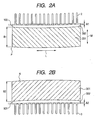
Fig. 2A is a plan view schematically showing a positive electrode of the lithium ion battery before being rolled up in the embodiment; and -
Fig. 2B is a plan view schematically showing a negative electrode of the lithium ion battery before being rolled up in the embodiment. - Now, one embodiment in which the invention is applied to a cylindrical lithium secondary battery for the HVE will be described below with reference to the accompanying drawings.
- In processes of manufacturing a positive electrode, Lithium-including double oxide powder as a positive-electrode active material, scaly graphite as a conductive material, and polyvinylidene fluoride (PVDF) as a binder are mixed at a ratio by weight of 85:10:5. Then, the mixture is kneaded with N-methylpyrrolidone (NMP) as dispersing solvent, thereby slurry is formed. The slurry is applied to both sides of aluminum foil having a thickness of 20 µm except for an area to form positive electrode lead pieces and the vicinity of them. Then, the aluminum foil with the slurry is dried, pressed, and cut to obtain a positive electrode. As shown in
Fig. 2A , the positive electrode formed by the above-mentioned processes is comprised of an active materialmixture layer portion 201 and an active material mixture layer-free portion 202, which are arranged on a surface of thealminum foil 100 in a width direction (W) of thealminum foil 100 corresponding to an axial direction (AX: refer toFig.1 ) of theelectrode assembly 6 and extended in a length direction (L) of thealuminum foil 100 lying at right angles to the width direction (W). The active material mixture layer free-portion 202 is arranged at one end side in the width direction (W) to be a part of collector. The active material mixture layer-free portion 202 is provided with positiveelectrode lead pieces 2 which are formed in like teeth of comb having each tooth width of several millimeters by cutting. Incidentally, the active material mixture layer-free portion 202 originally takes on a strip shape extending lengthwise as with the active materialmixture layer portion 201 before forming thelead pieces 2 by cutting. In the above-mentioned process, the positive electrode P is pressed with a predetermined load (for example, with "1 N" in this embodiment) so as to be extended in the length direction (L) of the electrode (in other words, the length direction of the aluminum foil before being rolled up). Thereby, the positive electrode P has the followings: a width (hereinafter the width is referred as a "positive-electrode active material mixture layer-width B1") of 80 to 84 mm as to the active materialmixture layer portion 201; a distance of 2 to 26 mm (hereinafter referred to as a "deviation A1") between a straight line linking both corners of the active material mixture layer-free portion 202 in the length direction of the electrode and an edge of the active material mixture layer-free portion 202 at a middle point in the length direction of the electrode; a thickness of 90 to 150 µm; and a length of 3.8 to 4.2 m. - In processes of manufacturing a negative electrode, 90 parts by weight of amorphous carbon powder as a negative-electrode active material and 10 parts by weight of PVDF as a binder were kneaded with NMP as a dispersing solvent, thereby slurry was formed. The slurry is applied to both sides of rolled
copper foil 101 having a thickness of 10 µm except for an area to form positive electrode lead pieces and the vicinity of them. Then, thecopper foil 101 with the slurry is dried, pressed, and cut to a negative electrode. As shown inFig. 2B , the negative electrode formed by the above-mentioned processes is comprised of an active materialmixture layer portion 301 and an active material mixture layer-free portion 302, which are arranged on a surface of the rolledcopper foil 101 in a width direction (W) of the rolledcopper foil 101 corresponding to the axial direction (AX: refer toFig.1 ) of theelectrode assembly 6 and extended in a length direction (L) of the rolledcopper foil 101 lying at right angles to the width direction (W). The active material mixture layer free-portion 302 is arranged at one end side in the width direction (W) to be a part of collector. The active material mixture layer-free portion 302 is provided with negativeelectrode lead pieces 3 which are formed in like teeth of comb having each tooth width of several millimeters by cutting. Incidentally, the active material mixture layer-free portion 302 originally takes on a strip shape extending lengthwise as with the active materialmixture layer portion 301 before forming thelead pieces 3 by cutting. In the above-mentioned process, the negative electrode N is pressed with a predetermined load (for example, with "1 N" in this embodiment) so as to be extended in the length direction (L) of the electrode (in other words, the length direction of the rolled copper foil). Thereby, the negative electrode N has the followings: a width (hereinafter the width is referred as a "negative-electrode active material mixture layer width B2") of 84 to 88 mm as to thestrip portion 301 of the active material mixture layer; a distance of 2 to 4 mm (hereinafter referred to as a "deviation A2") between a straight line linking both corners of the activematerialmixture layer-free portion 302 in the length direction of the electrode and an edge of the active material mixture layer-free portion 302 at a middle point in the length direction of the electrode; a thickness of 90 to 150 µm; and a length of 4.0 to 4.4 m. - As shown in
Fig. 1 , the positive electrode and the negative electrode manufactured as mentioned above are rolled up together with a porous polyethylene separator (not illustrated) having a width of 92 mm and a thickness of 40 µm such that the separator is interposed between the electrodes not to bring both electrodes into direct contact with each other, thereby to form a rolled-upelectrode assembly 6 serving as a set of electrodes. In rolling up them, the positive electrode, the negative electrode, and the separator are extended under a load of 10 N in the electrode length direction and in the separator longitudinal direction, while being rolled up and controlled along with meandering such that the ends of the electrodes and the ends of the separator in the width direction of the electrode (namely in the axial direction of the electrode assembly 6) are located in predetermined positions. A hollowcylindrical bobbin 1 made of polypropylene is disposed at a center of the rolled-upelectrode assembly 6. At this time, the positiveelectrode lead pieces 2 and the negativeelectrode lead pieces 3 are positioned at both ends of the rolled-upelectrode assembly 6 being opposed to each other. - The positive
electrode lead pieces 2 are bent to be collected and brought into contact with each other around a surface of a flange integrally formed with a positive electrodecurrent collector ring 4, and then connected to the surface of the flange by ultrasonic welding. On the other hand, connection of the negativeelectrode lead pieces 3 to a negative electrodecurrent collector ring 5 is performed in the same way as that of the positiveelectrode lead pieces 2 to the positive electrodecurrent collector ring 4. Thereafter, the entire surface of the flange of thecurrent collector ring 4 was coated with an insulating coating, and the rolled-upelectrode assembly 6 was inserted into abattery case 7 of steel coated with nickel plating. - The negative electrode
current collector ring 5 is previously welded to a negativeelectrode lead plate 8 for electric conduction. The negativeelectrode lead plate 8 is connected to the bottom of thecase 7 by welding after the rolled-upelectrode assembly 6 was inserted into thebattery case 7. - On the other hand, a
positive electrode lead 9, which is formed by previously laminating a plurality of ribbons made of aluminum, is connected to the positive electrodecurrent collector ring 4 by welding, and the other end of thepositive electrode lead 9 is connected to the lower surface of a battery lid for closing thebattery case 7 by welding. The battery lid includes alid case 12, alid cap 13, avalve holding member 14 for keeping sealing, and asafety valve 11. The battery lid is assembled by depositing these elements and crimping the peripheral edge of thelid case 12. - Then, a nonaqueous electrolyte solution is charged into the
battery case 7 in a predetermined amount to immerse the rolled-upelectrode assembly 6 thereinto. Thebattery case 7 is closed with the lid in such a manner to enable folding of thepositive electrode lead 9, and the battery lid is crimped and fixed to thecase 7 via agasket 10 made of EPDM resin to be sealed, thereby completing the manufacturing of a cylindrical lithium ion battery 20 (seeFig. 1 ). The nonaqueous electrolyte solution in use is one obtained by mixing ethylene carbonate and dimethyl carbonate at a volume ratio of 1:2, and lithium hexafluorophosphate (LiPF6) in use is dissolved into the liquid mixture described above at a concentration of 1 mol/liter. - As mentioned above, in the
lithium ion battery 20 of this embodiment, each of the positive and negative electrodes is provided with the active material mixture layer portion (201, 301) and the active material mixture layer free-portion (202, 302) which are arranged on the surface of the metal foil and extended along the length direction of the metal foil. The rolled-upelectrode assembly 6 is manufactured by rolling up the positive and negative electrodes interposing the separator therebetween. The rolled-upelectrode assembly 6 is immersed in the electrolyte solution and accommodated in thebattery case 7. In thelithium ion battery 20 of this embodiment, the negative-electrode active material mixture layer width B2 is set larger than the positive-electrode active material mixture layer width B1 (that is, B1 < B2), and that (deviation A1 + deviation A2) / (negative electrode active material mixture layer width B2 - positive electrode active material mixture layer width B2) is equal to or less than 4 (that is, (A1 + A2) / (B2 - B1) ≤ 4). - The lithium secondary battery generally uses lithium transition metal double oxide as the positive-electrode active material, and carbon material as the negative-electrode active material, like the
lithium ion battery 20. Lithium contained in the positive-electrode active material is ionized by the charge to move to the electrolyte solution, while lithium ions contained in the electrolyte solution are captured into the carbon material at the negative electrode. - In order to ensure such a reaction, in the lithium secondary battery, the amount of lithium captured by the negative-electrode active material is larger than that of lithium discharged from the positive-electrode active material, and the supply of the lithium from the positive-electrode active material is controlled not to be excessive with respect to the amount of reacted lithium of the negative-electrode active material. Further, the negative-electrode mixture layer is disposed at a surface opposed to the positive-electrode mixture layer. The reason is as follows. If the amount of supply of the lithium from the positive electrode is excessive, or if the amount of supply of the lithium being unevenly distributed due to the positive-electrode mixture layer not being opposed to the negative-electrode mixture layer, lithium dendrite may be locally produced at the surface of the negative electrode. Accordingly, the lithium dendrite may penetrate the separator for preventing short circuit between the positive and negative electrodes, thereby causing internal short circuit. Such problems is solved by the above-mentioned arrangement as to the control of the lithium supply amount and the positive-electrode mixture layer to the negative-electrode mixture layer.
- Incidentally, in general, each electrode of the battery for large current discharge (for example, a battery for the HEV including a capacity of 3 Ah or more) have the active material mixture layer-free portion, which is continuously formed at one side of the electrode along the length direction of a current collector-surface area of the metal foil (current collector foil), so as to enable the large current discharge. As mentioned above, in such electrodes, each metal foil although was rolled at a strip portion having the active material mixture layer portions (201 or 301) by press working for adjusting the density of the active material mixture layer, the metal foil has an area not been rolled by press working, namely the area of the active material mixture layer free-portion. As a result, a shape of the electrodes become distorted, which may cause positions where the positive electrode mixture layer and the negative electrode mixture layer are not opposed to each other via the separator due to the degree of distortions of the electrodes in manufacturing the electrode assembly.
- However, in the
lithium ion battery 20 of this embodiment, the negative-electrode active material mixture layer width B2 is set larger than the positive-electrode active mixture layer width B1 (that is, B1 < B2), and (deviation A1 + deviation A2)/(negative-electrode active material mixture layer width B2 - positive-electrode active material mixture layer width B2) is set equal to or less than 4 (that is, (A1 + A2) / (B2 - B1) ≤ 4). According to such an arrangement, since electrodes can have permissible distortion capable of opposing the positive electrode mixture layer and the negative electrode mixture layer to each other effectively, thelithium ion battery 20 enables the large current charge and discharge (serving as an inherent function of the battery for the HEV) , and can have both excellent charge and discharge characteristics and high safety without generating lithium dendrite. - In this embodiment, the lithium battery has electrodes with the active material mixture layer-free portions (202, 302) which have positive electrode leadpieces and negative electrode lead pieces like teeth of comb by cutting, respectively, but the invention is not limited to such active material mixture layer-free portions, for example, the lithium battery may have electrodes with the active material mixture layer-free portions with cutting-free electrode lead.
- Incidentally, in this embodiment, the cylindrical lithium secondary battery is embodied, the battery of the invention is not limited to the columnar or cylindrical shape, and thus may be applied to a square battery.
- Further, in this embodiment, the binder is PVDF, but the invention is not limited thereto. The binders may include polymer, such as polytetrafluoroethylene (PTFE), polyethylene, polystyrene, polybutadiene, butyl rubber, nitrile rubber, styrene/butadiene rubber, polysulfide rubber, cellulose nitrate, cyanoethyl cellulose, various kinds of latex, acrylic nitrile, vinyl fluoride, vinylidene fluoride, propylene fluoride, and chloroprene fluoride, and a mixture thereof.
- Further, this embodiment although uses the nonaqueous electrolyte solution prepared by dissolving LiPF6 in a liquid mixture of EC, DEC, and DMC, a general lithium salt may be used as an electrolyte, and a nonaqueous electrolyte solution formed by dissolving the salt in organic solvent may be used. That is, the invention is not limited to specific lithium salts and organic solvents. For example, electrolytes in use can be LiClO4, LiAsF6, LiBF4, LiB(C6H5)4, CH3SO3Li, CF3SO3Li, and a mixture thereof. The organic solvents may be in use, for example, propylene carbonate, ethylene carbonate, 1,2-dimethoxyethane, 1,2-diethoxyethan, γ-butyrolactone, tetraphydrofuran, 1,3-dioxolan, 4-methyl-1,3-dioxolan, diethyl ether, sulfolane, methylsulolane, acetonitrile, propionitrile, or a mixed refrigerant containing two or more of the above-mentioned solvents. The mixing ratio thereof is not limited to a specific one.
- Now, examples of the cylindrical
lithium ion battery 20 manufactured according to the above-mentioned embodiments will be described below. Comparison examples of batteries manufactured for comparison will also be described below. - As shown in the following table 1, a battery of Example 1 in use included a positive electrode having a positive-electrode active material mixture layer width B1 of 80 mm (B1 = 80 mm), and a deviation A1 of 2 mm (A1 = 2 mm), and a negative electrode having a negative-electrode active material mixture layer width B2 of 85 mm (B2 = 85 mm), and a deviation A2 of 2 mm (A2 = 2 mm). A designed battery capacity was 5.6 Ah.
[Table 1] Item Positive-elect rode active material mixture layer width B1 (mm) Negative-elect rode active material mixture layer width B2 (mm) A1 (mm) A2 (mm) Example 1 80 85 2 2 Example 2 80 85 6 2 Example 3 80 85 10 2 Example 4 80 85 14 2 Example 5 80 85 18 2 Example 6 80 84 2 2 Example 7 80 84 6 2 Example 8 80 84 10 2 Example 9 80 84 14 2 Example10 80 84 2 4 Example11 80 84 6 4 Example12 80 84 10 4 Example13 84 88 2 2 Example14 84 88 6 2 Example15 84 88 10 2 Example16 84 88 14 2 Comparative Example 1 80 85 22 2 Comparative Example 2 80 85 26 2 ComparativeExample 380 84 18 2 Comparative Example 4 80 84 22 2 Comparative Example 5 80 84 14 4 Comparative Example 6 80 84 18 4 Comparative Example 7 84 88 18 2 Comparative Example 8 84 88 22 2 - As shown in Table 1, a battery of Example 2 was manufactured in the same way as that of Example 1 except that the battery of Example 2 in use included a positive electrode having a positive-electrode active material mixture layer width B1 of 80 mm (B1 = 80 mm), and a deviation A1 of 6 mm (A1 = 6 mm), and a negative electrode having a negative-electrode active material mixture layer width B2 of 85 mm (B2 = 85 mm) , and a deviation A2 of 2 mm (A2 = 2 mm). (Designed battery capacity : 5.6 Ah)
- As shown in Table 1, a battery of Example 3 was manufactured in the same way as that of Example 1 except that the battery of Example 3 in use included a positive electrode having a positive-electrode active material mixture layer width B1 of 80 mm (B1 = 80 mm), and a deviation A1 of 10 mm (A1 = 10 mm), and a negative electrode having a negative-electrode active material mixture layer width B2 of 85 mm (B2 = 85 mm), and a deviation A2 of 2 mm (A2 = 2 mm). (Designed battery capacity : 5.6 Ah)
- As shown in Table 1, a battery of Example 4 was manufactured in the same way as that of Example 1 except that the battery of Example 4 in use included a positive electrode having a positive-electrode active material mixture layer width B1 of 80 mm (B1 = 80 mm), and a deviation A1 of 14 mm (A1 = 14 mm), and a negative electrode having a negative-electrode active material mixture layer width B2 of 85 mm (B2 = 85 mm), and a deviation A2 of 2 mm (A2 = 2 mm). (Designed battery capacity : 5.6 Ah)
- As shown in Table 1, a battery of Example 5 was manufactured in the same way as that of Example 1 except that the battery of Example 5 in use included a positive electrode having a positive-electrode active material mixture layer width B1 of 80 mm (B1 = 80 mm) , and a deviation A1 of 18 mm (A1 = 18 mm) , and a negative electrode having a negative-electrode active material mixture layer width B2 of 85 mm (B2 = 85 mm), and a deviation A2 of 2 mm (A2 = 2 mm). (Designed battery capacity : 5.6 Ah)
- As shown in Table 1, a battery of Example 6 was manufactured in the same way as that of Example 1 except that the battery of Example 6 in use included a positive electrode having a positive-electrode active material mixture layer width B1 of 80 mm (B1 = 80 mm), and a deviation A1 of 2 mm (A1 = 2 mm), and a negative electrode having a negative-electrode active material mixture layer width B2 of 84 mm (B2 = 84 mm), and a deviation A2 of 2 mm (A2 = 2 mm). (Designed battery capacity : 5.6 Ah)
- As shown in Table 1, a battery of Example 7 was manufactured in the same way as that of Example 1 except that the battery of Example 7 in use included a positive electrode having a positive-electrode active material mixture layer width B1 of 80 mm (B1 = 80 mm), and a deviation A1 of 6 mm (A1 = 6 mm), and a negative electrode having a negative-electrode active material mixture layer width B2 of 84 mm (B2 = 84 mm), and a deviation A2 of 2 mm (A2 = 2 mm). (Designed battery capacity : 5.6 Ah)
- As shown in Table 1, a battery of Example 8 was manufactured in the same way as that of Example 1 except that the battery of Example 8 in use included a positive electrode having a positive-electrode active material mixture layer width B1 of 80 mm (B1 = 80 mm), and a deviation A1 of 10 mm (A1 = 10 mm), and a negative electrode having a negative-electrode active material mixture layer width B2 of 84 mm (B2 = 84 mm), and a deviation A2 of 2 mm (A2 = 2 mm). (Designed battery capacity : 5.6 Ah)
- As shown in Table 1, a battery of Example 9 was manufactured in the same way as that of Example 1 except that the battery of Example 9 in use included a positive electrode having a positive-electrode active material mixture layer width B1 of 80 mm (B1 = 80 mm), and a deviation A1 of 14 mm (A1 = 14 mm), and a negative electrode having a negative-electrode active material mixture layer width B2 of 84 mm (B2 = 84 mm), and a deviation A2 of 2 mm (A2 = 2 mm). (Designed battery capacity : 5.6 Ah)
- As shown in Table 1, a battery of Example 10 was manufactured in the same way as that of Example 1 except that the battery of Example 10 in use included a positive electrode having a positive-electrode active material mixture layer width B1 of 80 mm (B1 = 80 mm), and a deviation A1 of 2 mm (A1 = 2 mm), and a negative electrode having a negative-electrode active material mixture layer width B2 of 84 mm (B2 = 84 mm), and a deviation A2 of 4 mm (A2 = 4 mm). (Designed battery capacity : 5.6 Ah)
- As shown in Table 1, a battery of Example 11 was manufactured in the same way as that of Example 1 except that the battery of Example 11 in use included a positive electrode having a positive-electrode active material mixture layer width B1 of 80 mm (B1 = 80 mm), and a deviation A1 of 6 mm (A1 = 6 mm), and a negative electrode having a negative-electrode active material mixture layer width B2 of 84 mm (B2 = 84 mm), and a deviation A2 of 4 mm (A2 = 4 mm). (Designed battery capacity : 5.6 Ah)
- As shown in Table 1, a battery of Example 12 was manufactured in the same way as that of Example 1 except that the battery of Example 12 in use included a positive electrode having a positive-electrode active material mixture layer width B1 of 80 mm (B1 = 80 mm), and a deviation A1 of 10 mm (A1 = 10 mm), and a negative electrode having a negative-electrode active material mixture layer width B2 of 84 mm (B2 = 84 mm), and a deviation A2 of 4 mm (A2 = 4 mm). (Designed battery capacity : 5.6 Ah)
- As shown in Table 1, a battery of Example 13 was manufactured in the same way as that of Example 1 except that the battery of Example 13 in use included a positive electrode having a positive-electrode active material mixture layer width B1 of 84 mm (B1 = 84 mm), and a deviation A1 of 2 mm (A1 = 2 mm) , and a negative electrode having a negative-electrode active material mixture layer width B2 of 88 mm (B2 = 88 mm), and a deviation A2 of 2 mm (A2 = 2 mm). (Designed battery capacity : 5.9 Ah)
- As shown in Table 1, a battery of Example 14 was manufactured in the same way as that of Example 1 except that the battery of Example 14 in use included a positive electrode having a positive-electrode active material mixture layer width B1 of 84 mm (B1 = 84 mm), and a deviation A1 of 6 mm (A1 = 6 mm), and a negative electrode having a negative-electrode active material mixture layer width B2 of 88 mm (B2 = 88 mm), and a deviation A2 of 2 mm (A2 = 2 mm). (Designed battery capacity : 5.9 Ah)
- As shown in Table 1, a battery of Example 15 was manufactured in the same way as that of Example 1 except that the battery of Example 15 in use included a positive electrode having a positive-electrode active material mixture layer width B1 of 84 mm (B1 = 84 mm), and a deviation A1 of 10 mm (A1 = 10 mm), and a negative electrode having a negative-electrode active material mixture layer width B2 of 88 mm (B2 = 88 mm), and a deviation A2 of 2 mm (A2 = 2 mm). (Designed battery capacity : 5.9 Ah)
- As shown in Table 1, a battery of Example 16 was manufactured in the same way as that of Example 1 except that the battery of Example 16 in use included a positive electrode having a positive-electrode active material mixture layer width B1 of 84 mm (B1 = 84 mm), and a deviation A1 of 14 mm (A1 = 14 mm) , and a negative electrode having a negative-electrode active material mixture layer width B2 of 88 mm (B2 = 88 mm), and a deviation A2 of 2 mm (A2 = 2 mm). (Designed battery capacity : 5.9 Ah)
- As shown in Table 1, a battery of Comparative Example 1 was manufactured in the same way as that of Example 1 except that the battery of Comparative Example 1 in use included a positive electrode having a positive-electrode active material mixture layer width B1 of 80 mm (B1 = 80 mm) , and a deviation A1 of 22 mm (A1 = 22 mm), and a negative electrode having a negative-electrode active material mixture layer width B2 of 85 mm (B2 = 85 mm), and a deviation A2 of 2 mm (A2 = 2 mm).
- As shown in Table 1, a battery of Comparative Example 2 was manufactured in the same way as that of Example 1 except that the battery of Comparative Example 2 in use included a positive electrode having a positive-electrode active material mixture layer width B1 of 80 mm (B1 = 80 mm) , and a deviation A1 of 26 mm (A1 = 26 mm), and a negative electrode having a negative-electrode active material mixture layer width B2 of 85 mm (B2 = 85 mm), and a deviation A2 of 2 mm (A2 = 2 mm).
- As shown in Table 1, a battery of Comparative Example 3 was manufactured in the same way as that of Example 1 except that the battery of Comparative Example 3 in use included a positive electrode having a positive-electrode active material mixture layer width B1 of 80 mm (B1 = 80 mm) , and a deviation A1 of 18 mm (A1 = 18 mm), and a negative electrode having a negative-electrode active material mixture layer width B2 of 84 mm (B2 = 84 mm), and a deviation A2 of 2 mm (A2 = 2 mm).
- As shown in Table 1, a battery of Comparative Example 4 was manufactured in the same way as that of Example 1 except that the battery of Comparative Example 4 in use included a positive electrode having a positive-electrode active material mixture layer width B1 of 80 mm (B1 = 80 mm), and a deviation A1 of 22 mm (A1 = 22 mm), and a negative electrode having a negative-electrode active material mixture layer width B2 of 84 mm (B2 = 84 mm), and a deviation A2 of 2 mm (A2 = 2 mm).
- As shown in Table 1, a battery of Comparative Example 5 was manufactured in the same way as that of Example 1 except that the battery of Comparative Example 5 in use included a positive electrode having a positive-electrode active material mixture layer width B1 of 80 mm (B1 = 80 mm), and a deviation A1 of 14 mm (A1 = 14 mm), and a negative electrode having a negative-electrode active material mixture layer width B2 of 84 mm (B2 = 84 mm), and a deviation A2 of 4 mm (A2 = 4 mm).
- As shown in Table 1, a battery of Comparative Example 6 was manufactured in the same way as that of Example 1 except that the battery of Comparative Example 6 in use included a positive electrode having a positive-electrode active material mixture layer width B1 of 80 mm (B1 = 80 mm), and a deviation A1 of 18 mm (A1 = 18 mm), and a negative electrode having a negative-electrode active material mixture layer width B2 of 84 mm (B2 = 84 mm), and a deviation A2 of 4 mm (A2 = 4 mm).
- As shown in Table 1, a battery of Comparative Example 7 was manufactured in the same way as that of Example 1 except that the battery of Comparative Example 7 in use included a positive electrode having a positive-electrode active material mixture layer width B1 of 84 mm (B1 = 84 mm) , and a deviation A1 of 18 mm (A1 = 18 mm), and a negative electrode having a negative-electrode active material mixture layer width B2 of 88 mm (B2 = 88 mm), and a deviation A2 of 2 mm (A2 = 2 mm).
- As shown in Table 1, a battery of Comparative Example 8 was manufactured in the same way as that of Example 1 except that the battery of Comparative Example 8 in use included a positive electrode having a positive-electrode active material mixture layer width B1 of 84 mm (B1 = 84 mm) , and a deviation A1 of 22 mm (A1 = 22 mm), and a negative electrode having a negative-electrode active material mixture layer width B2 of 88 mm (B2 = 88 mm), and a deviation A2 of 2 mm (A2 = 2 mm).
- First, 10 batteries per example or comparison example having each specification described above were manufactured, and then evaluated as follows. (A) A charge and discharge cycle test of each battery were performed for 100 cycles on a constant current charging condition in which the battery was charged up to a charging end voltage of 4.1 V and on a constant current discharging condition in which the battery was discharged up to a discharging end voltage of 2.7 V, using large current of 60A (at about 0.1 hour rate). The battery after 100 cycles was charged up to 3. 6 V, and then a decrease in voltage of the battery was measured for 30 days. The battery whose voltage was equal to or more than 3.55 V after 30 days was determined not to have a small internal short circuit. The battery whose voltage was below 3.55 V after 30 days was determined to have the small internal short circuit. (B) On the other hand, the battery after measuring the decrease in voltage was disassembled, and the presence or absence of a position where the positive-electrode active material layer and the negative-electrode active material layer were not opposed to each other was examined. Further, a value of (A1 + A2) / (B2 - B1) = K (hereinafter referred to as a "K value") of each battery of Examples and Comparative Examples was determined. The results of the tests and examination and the K values are shown in the following table 2.
Item Number of batteries determined to have small internal short circuit Number of batteries having parts not opposed K value Example 1 0 0 0.8 Example 2 0 0 1.6 Example 3 0 0 2.4 Example 4 0 0 3.2 Example 5 0 0 4.0 Example 6 0 0 1.0 Example 7 0 0 2.0 Example 8 0 0 3.0 Example 9 0 0 4.0 Example 10 0 0 1.5 Example 11 0 0 2.5 Example 12 0 0 3.5 Example 13 0 0 1.0 Example 14 0 0 2.0 Example 15 0 0 3.0 Example 16 0 0 4.0 Comparative Example 1 10 10 4.8 Comparative Example 2 10 10 5.6 Comparative Example 3 10 10 5.0 Comparative Example 4 10 10 6.0 Comparative Example 5 10 10 4.5 Comparative Example 6 10 10 5.5 Comparative Example 7 10 10 5.0 Comparative Example 8 10 10 6.0 - As shown in Table 2, the battery having a K value of 4 or less did not have any small short circuit in the battery, and did not have any positions where the positive-electrode mixture layer and the negative-electrode mixture layer were not opposed to each other. In short, the battery having the K value of 4 or less enables the large current charge and discharge and has excellent standing characteristics after the charging without any small internal short circuit. The negative-electrode active material mixture layer width B2 is set larger than the positive-electrode active material mixture layer width B1, so that lithium dendrite can be prevented from locally occurring at the surface of the negative electrode even when the amount of supply of the lithium is unevenly distributed. From the above-mentioned fact, the batteries of Examples are determined to have excellent charge and discharge characteristics and safety.
- The invention provides a lithium secondary battery that enables large current charge and discharge with both excellent charge and discharge characteristics and safety. Therefore, the invention has industrial applicability in that it contributes to the production and sale of lithium secondary batteries.
Claims (4)
- A lithium secondary battery comprising an electrode assembly (6) accommodated in a battery case (7), said electrode assembly (6) including a positive electrode (2) and a negative electrode (3) which are assembled together with a separator interposing between said both electrodes (2, 3), each of said electrodes (2, 3) including an active material mixture layer portion (201, 301) and an active material mixture layer free-portion (202, 302) which are arranged on a surface of a metal foil in a width direction of the metal foil corresponding to an axial direction of said electrode assembly (6) and extended in a length direction of said metal foil lying at right angles to said width direction, and said active material mixture layer free-portion (202, 302) arranged at one end side in said width direction to be a part of a collector,
wherein a relationship of B1 < B2 is satisfied, and a value of (A1+A2) / (B2 -B1) is set equal to or less than 4, where B1 (mm) is a width of said active material mixture layer portion (201) of said positive electrode (2); B2 (mm) is a width of said active material mixture layer portion (301) of said negative electrode (3); and each of A1 (mm) in said positive electrode (2) and A2 (mm) in said negative electrode (3) is a deviation between a straight line linking both corners of said active material mixture layer-free portion (202, 302) in said length direction of said metal foil in the corresponding electrode having been extended by a predetermined load and an edge of said active material mixture layer-free portion (202, 302) at a middle point in said length direction of said metal foil. - The lithium secondary battery according to claim 1, wherein said active material mixture layer portion (201) of saidpositive electrode (2) contains lithium transition metal double oxide, and said active material mixture layer portion of said negative electrode (3) contains carbon material.
- The lithium secondary battery according to claim 1 or 2, wherein each of said electrodes (2, 3) has been extended in its length direction by being subjected to the predetermined load before being assembled.
- The lithium secondary battery according to claim 1, wherein said battery has a capacity of 3 Ah or more, and a maximum discharge current value of 60 A or more.
Applications Claiming Priority (1)
| Application Number | Priority Date | Filing Date | Title |
|---|---|---|---|
| JP2008011142A JP5300274B2 (en) | 2008-01-22 | 2008-01-22 | Lithium secondary battery |
Publications (2)
| Publication Number | Publication Date |
|---|---|
| EP2083464A1 true EP2083464A1 (en) | 2009-07-29 |
| EP2083464B1 EP2083464B1 (en) | 2012-05-16 |
Family
ID=40568190
Family Applications (1)
| Application Number | Title | Priority Date | Filing Date |
|---|---|---|---|
| EP09000830A Active EP2083464B1 (en) | 2008-01-22 | 2009-01-22 | Lithium secondary battery |
Country Status (5)
| Country | Link |
|---|---|
| US (1) | US8367243B2 (en) |
| EP (1) | EP2083464B1 (en) |
| JP (1) | JP5300274B2 (en) |
| KR (1) | KR101275677B1 (en) |
| CN (1) | CN101494301B (en) |
Cited By (2)
| Publication number | Priority date | Publication date | Assignee | Title |
|---|---|---|---|---|
| EP2755258A1 (en) * | 2013-01-11 | 2014-07-16 | GS Yuasa International Ltd. | Electric storage device, electric storage system, and manufacturing method thereof |
| WO2017174374A1 (en) * | 2016-04-08 | 2017-10-12 | Lithium Energy and Power GmbH & Co. KG | Energy storage device |
Families Citing this family (11)
| Publication number | Priority date | Publication date | Assignee | Title |
|---|---|---|---|---|
| KR100973312B1 (en) | 2008-03-25 | 2010-07-30 | 삼성에스디아이 주식회사 | Center pin for secondary battery and secondary battery having same |
| JP5103496B2 (en) * | 2010-03-09 | 2012-12-19 | 日立ビークルエナジー株式会社 | Lithium ion secondary battery |
| JP5690579B2 (en) * | 2010-12-24 | 2015-03-25 | 日立オートモティブシステムズ株式会社 | Lithium ion secondary battery |
| WO2020175632A1 (en) * | 2019-02-27 | 2020-09-03 | Tdk株式会社 | All-solid-state battery |
| CN112531221A (en) * | 2020-12-03 | 2021-03-19 | 天津空间电源科技有限公司 | Winding type lithium ion battery with integrated electric connection structure and forming process thereof |
| CA3202317A1 (en) | 2021-01-19 | 2022-07-28 | Lg Energy Solution, Ltd. | Battery and current collector applied thereto, and battery pack and vehicle including the same |
| US12132227B2 (en) | 2021-01-19 | 2024-10-29 | Lg Energy Solution, Ltd. | Battery, and battery pack and vehicle comprising the same |
| US12407028B2 (en) | 2021-02-19 | 2025-09-02 | Lg Energy Solution, Ltd. | Electrode assembly, battery, and battery pack and vehicle including the same |
| US20240387833A1 (en) * | 2021-11-08 | 2024-11-21 | Lg Energy Solution, Ltd. | Current collector for secondary battery and cylindrical battery cell comprising the same |
| EP4307461A4 (en) | 2021-11-19 | 2025-10-29 | Lg Energy Solution Ltd | ELECTRODE ARRANGEMENT, BATTERY AND BATTERY PACK AS WELL AS VEHICLE WITH IT |
| CN120202554A (en) * | 2023-05-19 | 2025-06-24 | 宁德时代新能源科技股份有限公司 | Positive electrode sheet, electrode assembly, battery cell, battery and electrical equipment |
Citations (4)
| Publication number | Priority date | Publication date | Assignee | Title |
|---|---|---|---|---|
| US6432574B1 (en) * | 1999-06-28 | 2002-08-13 | Nec Corporation | Electrode tab for a nonaqueous electrolyte secondary battery and method of forming the same |
| JP2005268139A (en) | 2004-03-22 | 2005-09-29 | Shin Kobe Electric Mach Co Ltd | Winding battery |
| US20070048615A1 (en) * | 2005-08-25 | 2007-03-01 | Masatoshi Nagayama | Non-aqueous electrolyte secondary battery and battery pack using the same |
| US20070048613A1 (en) * | 2005-08-30 | 2007-03-01 | Sanyo Electric Co., Ltd. | Nonaqueous secondary battery |
Family Cites Families (14)
| Publication number | Priority date | Publication date | Assignee | Title |
|---|---|---|---|---|
| JPH0896839A (en) * | 1994-09-22 | 1996-04-12 | Sony Corp | Lithium ion secondary battery |
| JPH11162516A (en) * | 1997-11-25 | 1999-06-18 | Fuji Photo Film Co Ltd | Lithium ion battery and its manufacture |
| JPH11185736A (en) * | 1997-12-16 | 1999-07-09 | Toyota Central Res & Dev Lab Inc | Manufacturing method of sheet electrode |
| JP4366783B2 (en) * | 1998-11-16 | 2009-11-18 | 株式会社デンソー | Multilayer battery and method of manufacturing electrode thereof |
| JP2000188103A (en) * | 1998-12-21 | 2000-07-04 | Toshiba Battery Co Ltd | Rolling device for battery electrode body |
| JP4233670B2 (en) * | 1999-03-01 | 2009-03-04 | パナソニック株式会社 | Method for producing non-aqueous electrolyte secondary battery |
| JP3683134B2 (en) * | 1999-09-02 | 2005-08-17 | トヨタ自動車株式会社 | Manufacturing method of sheet electrode |
| US20030190530A1 (en) * | 2000-03-28 | 2003-10-09 | Li Yang | Lithium Secondary Battery |
| US6803149B2 (en) * | 2000-12-04 | 2004-10-12 | Shin-Kobe Electric Machinery Co., Ltd. | Non-aqueous electrolytic solution secondary battery |
| WO2002065561A1 (en) * | 2001-02-14 | 2002-08-22 | Sony Corporation | Non-aqueous electrolytic battery |
| KR100490548B1 (en) * | 2002-12-27 | 2005-05-17 | 삼성에스디아이 주식회사 | Secondary battery with jelly-roll type electrode assembly |
| JP4238630B2 (en) * | 2003-05-09 | 2009-03-18 | 株式会社デンソー | Electrode manufacturing method |
| JP2005339926A (en) * | 2004-05-26 | 2005-12-08 | Yuasa Corp | Strip electrode and battery using the same |
| JP4954585B2 (en) * | 2006-03-31 | 2012-06-20 | 株式会社デンソー | Method for producing electrode for lithium ion battery |
-
2008
- 2008-01-22 JP JP2008011142A patent/JP5300274B2/en active Active
-
2009
- 2009-01-12 CN CN2009100020659A patent/CN101494301B/en active Active
- 2009-01-21 KR KR1020090005113A patent/KR101275677B1/en active Active
- 2009-01-22 US US12/357,518 patent/US8367243B2/en active Active
- 2009-01-22 EP EP09000830A patent/EP2083464B1/en active Active
Patent Citations (4)
| Publication number | Priority date | Publication date | Assignee | Title |
|---|---|---|---|---|
| US6432574B1 (en) * | 1999-06-28 | 2002-08-13 | Nec Corporation | Electrode tab for a nonaqueous electrolyte secondary battery and method of forming the same |
| JP2005268139A (en) | 2004-03-22 | 2005-09-29 | Shin Kobe Electric Mach Co Ltd | Winding battery |
| US20070048615A1 (en) * | 2005-08-25 | 2007-03-01 | Masatoshi Nagayama | Non-aqueous electrolyte secondary battery and battery pack using the same |
| US20070048613A1 (en) * | 2005-08-30 | 2007-03-01 | Sanyo Electric Co., Ltd. | Nonaqueous secondary battery |
Cited By (5)
| Publication number | Priority date | Publication date | Assignee | Title |
|---|---|---|---|---|
| EP2755258A1 (en) * | 2013-01-11 | 2014-07-16 | GS Yuasa International Ltd. | Electric storage device, electric storage system, and manufacturing method thereof |
| US9431680B2 (en) | 2013-01-11 | 2016-08-30 | Gs Yuasa International Ltd. | Electric storage device, electric storage system, and manufacturing method thereof |
| WO2017174374A1 (en) * | 2016-04-08 | 2017-10-12 | Lithium Energy and Power GmbH & Co. KG | Energy storage device |
| CN108886128A (en) * | 2016-04-08 | 2018-11-23 | 锂能源和电力有限责任两合公司 | energy storage device |
| CN108886128B (en) * | 2016-04-08 | 2023-01-13 | 株式会社杰士汤浅国际 | Energy storage device |
Also Published As
| Publication number | Publication date |
|---|---|
| JP2009176449A (en) | 2009-08-06 |
| CN101494301B (en) | 2011-06-15 |
| JP5300274B2 (en) | 2013-09-25 |
| US8367243B2 (en) | 2013-02-05 |
| KR101275677B1 (en) | 2013-06-14 |
| EP2083464B1 (en) | 2012-05-16 |
| KR20090080911A (en) | 2009-07-27 |
| US20090186278A1 (en) | 2009-07-23 |
| CN101494301A (en) | 2009-07-29 |
Similar Documents
| Publication | Publication Date | Title |
|---|---|---|
| EP2083464B1 (en) | Lithium secondary battery | |
| EP1920916B1 (en) | Assembled battery | |
| US7807292B2 (en) | Secondary battery | |
| JP5456542B2 (en) | Rectangular secondary battery and method for manufacturing prismatic secondary battery | |
| EP3010073B1 (en) | Positive electrode mixture paste, positive electrode, nonaqueous electrolyte secondary battery, and manufacturing method of nonaqueous electrolyte secondary battery | |
| US10424816B2 (en) | Lithium-ion secondary battery and manufacturing method thereof | |
| US20160254569A1 (en) | Assembled battery | |
| JP2005353519A (en) | Electrochemical element | |
| JP5173095B2 (en) | Sealed battery | |
| EP3238292B1 (en) | Method of manufacturing nonaqueous electrolyte secondary battery, and battery assembly | |
| JP4204231B2 (en) | Lithium secondary battery | |
| EP2779279B1 (en) | Battery | |
| KR20160027088A (en) | Nonaqueous electrolyte secondary cell and method for producing same | |
| CN106025169B (en) | Electric storage element | |
| US8822070B2 (en) | Battery with secure short-circuiting mechanism | |
| JP2003007346A (en) | Lithium secondary battery and method of manufacturing the same | |
| JP2009266706A (en) | Lithium-ion secondary battery | |
| JP2000090932A (en) | Lithium secondary battery | |
| WO2020137818A1 (en) | Non-aqueous electrolyte secondary battery and method for manufacturing same | |
| JP7211528B2 (en) | secondary battery | |
| EP3905413B1 (en) | Non-aqueous electrolyte secondary battery | |
| JP2005100955A (en) | Winding lithium-ion battery | |
| JPH11238500A (en) | Wound cylindrical battery | |
| JP2000182656A (en) | Lithium secondary battery | |
| JP4688527B2 (en) | Lithium secondary battery |
Legal Events
| Date | Code | Title | Description |
|---|---|---|---|
| PUAI | Public reference made under article 153(3) epc to a published international application that has entered the european phase |
Free format text: ORIGINAL CODE: 0009012 |
|
| 17P | Request for examination filed |
Effective date: 20090206 |
|
| AK | Designated contracting states |
Kind code of ref document: A1 Designated state(s): AT BE BG CH CY CZ DE DK EE ES FI FR GB GR HR HU IE IS IT LI LT LU LV MC MK MT NL NO PL PT RO SE SI SK TR |
|
| AX | Request for extension of the european patent |
Extension state: AL BA RS |
|
| 17Q | First examination report despatched |
Effective date: 20100305 |
|
| AKX | Designation fees paid |
Designated state(s): DE FR GB |
|
| GRAP | Despatch of communication of intention to grant a patent |
Free format text: ORIGINAL CODE: EPIDOSNIGR1 |
|
| RIC1 | Information provided on ipc code assigned before grant |
Ipc: H01M 4/133 20100101ALN20111020BHEP Ipc: H01M 4/131 20100101ALN20111020BHEP Ipc: H01M 4/70 20060101AFI20111020BHEP Ipc: H01M 10/0583 20100101ALI20111020BHEP Ipc: H01M 2/26 20060101ALI20111020BHEP |
|
| GRAS | Grant fee paid |
Free format text: ORIGINAL CODE: EPIDOSNIGR3 |
|
| GRAA | (expected) grant |
Free format text: ORIGINAL CODE: 0009210 |
|
| AK | Designated contracting states |
Kind code of ref document: B1 Designated state(s): DE FR GB |
|
| REG | Reference to a national code |
Ref country code: GB Ref legal event code: FG4D |
|
| REG | Reference to a national code |
Ref country code: DE Ref legal event code: R096 Ref document number: 602009006909 Country of ref document: DE Effective date: 20120719 |
|
| PLBE | No opposition filed within time limit |
Free format text: ORIGINAL CODE: 0009261 |
|
| STAA | Information on the status of an ep patent application or granted ep patent |
Free format text: STATUS: NO OPPOSITION FILED WITHIN TIME LIMIT |
|
| 26N | No opposition filed |
Effective date: 20130219 |
|
| REG | Reference to a national code |
Ref country code: DE Ref legal event code: R097 Ref document number: 602009006909 Country of ref document: DE Effective date: 20130219 |
|
| REG | Reference to a national code |
Ref country code: DE Ref legal event code: R082 Ref document number: 602009006909 Country of ref document: DE Representative=s name: BEETZ & PARTNER PATENT- UND RECHTSANWAELTE, DE |
|
| REG | Reference to a national code |
Ref country code: GB Ref legal event code: 732E Free format text: REGISTERED BETWEEN 20140828 AND 20140903 |
|
| REG | Reference to a national code |
Ref country code: DE Ref legal event code: R082 Ref document number: 602009006909 Country of ref document: DE Representative=s name: BEETZ & PARTNER PATENT- UND RECHTSANWAELTE, DE Effective date: 20140903 Ref country code: DE Ref legal event code: R081 Ref document number: 602009006909 Country of ref document: DE Owner name: HITACHI AUTOMOTIVE SYSTEMS, LTD., HITACHINAKA-, JP Free format text: FORMER OWNER: HITACHI VEHICLE ENERGY, LTD., HITACHINAKA-SHI, IBARAKI, JP Effective date: 20140903 Ref country code: DE Ref legal event code: R082 Ref document number: 602009006909 Country of ref document: DE Representative=s name: BEETZ & PARTNER MBB, DE Effective date: 20140903 Ref country code: DE Ref legal event code: R082 Ref document number: 602009006909 Country of ref document: DE Representative=s name: BEETZ & PARTNER MBB PATENTANWAELTE, DE Effective date: 20140903 Ref country code: DE Ref legal event code: R082 Ref document number: 602009006909 Country of ref document: DE Representative=s name: BEETZ & PARTNER MBB PATENT- UND RECHTSANWAELTE, DE Effective date: 20140903 |
|
| REG | Reference to a national code |
Ref country code: FR Ref legal event code: TP Owner name: HITACHI AUTOMOTIVE SYSTEMS, LTD., JP Effective date: 20141002 |
|
| REG | Reference to a national code |
Ref country code: FR Ref legal event code: PLFP Year of fee payment: 8 |
|
| REG | Reference to a national code |
Ref country code: FR Ref legal event code: PLFP Year of fee payment: 9 |
|
| REG | Reference to a national code |
Ref country code: FR Ref legal event code: PLFP Year of fee payment: 10 |
|
| REG | Reference to a national code |
Ref country code: DE Ref legal event code: R082 Ref document number: 602009006909 Country of ref document: DE Representative=s name: BEETZ & PARTNER MBB PATENTANWAELTE, DE Ref country code: DE Ref legal event code: R081 Ref document number: 602009006909 Country of ref document: DE Owner name: VEHICLE ENERGY JAPAN INC., HITACHINAKA-SHI, JP Free format text: FORMER OWNER: HITACHI AUTOMOTIVE SYSTEMS, LTD., HITACHINAKA-SHI, IBARAKI, JP |
|
| REG | Reference to a national code |
Ref country code: GB Ref legal event code: 732E Free format text: REGISTERED BETWEEN 20200423 AND 20200429 |
|
| PGFP | Annual fee paid to national office [announced via postgrant information from national office to epo] |
Ref country code: GB Payment date: 20251204 Year of fee payment: 18 |
|
| PGFP | Annual fee paid to national office [announced via postgrant information from national office to epo] |
Ref country code: FR Payment date: 20251128 Year of fee payment: 18 |
|
| PGFP | Annual fee paid to national office [announced via postgrant information from national office to epo] |
Ref country code: DE Payment date: 20251203 Year of fee payment: 18 |