EP2083350B1 - Radialsteuerungsmenü, grafische Nutzerschnittstelle, Verfahren zur Variablensteuerung und computerlesbares Medium zur Durchführung des Verfahrens - Google Patents
Radialsteuerungsmenü, grafische Nutzerschnittstelle, Verfahren zur Variablensteuerung und computerlesbares Medium zur Durchführung des Verfahrens Download PDFInfo
- Publication number
- EP2083350B1 EP2083350B1 EP09000857.4A EP09000857A EP2083350B1 EP 2083350 B1 EP2083350 B1 EP 2083350B1 EP 09000857 A EP09000857 A EP 09000857A EP 2083350 B1 EP2083350 B1 EP 2083350B1
- Authority
- EP
- European Patent Office
- Prior art keywords
- wedge
- menu
- variable
- cursor
- value
- Prior art date
- Legal status (The legal status is an assumption and is not a legal conclusion. Google has not performed a legal analysis and makes no representation as to the accuracy of the status listed.)
- Ceased
Links
Images


Classifications
-
- G—PHYSICS
- G06—COMPUTING OR CALCULATING; COUNTING
- G06F—ELECTRIC DIGITAL DATA PROCESSING
- G06F3/00—Input arrangements for transferring data to be processed into a form capable of being handled by the computer; Output arrangements for transferring data from processing unit to output unit, e.g. interface arrangements
- G06F3/01—Input arrangements or combined input and output arrangements for interaction between user and computer
- G06F3/048—Interaction techniques based on graphical user interfaces [GUI]
- G06F3/0484—Interaction techniques based on graphical user interfaces [GUI] for the control of specific functions or operations, e.g. selecting or manipulating an object, an image or a displayed text element, setting a parameter value or selecting a range
- G06F3/04847—Interaction techniques to control parameter settings, e.g. interaction with sliders or dials
-
- G—PHYSICS
- G06—COMPUTING OR CALCULATING; COUNTING
- G06F—ELECTRIC DIGITAL DATA PROCESSING
- G06F3/00—Input arrangements for transferring data to be processed into a form capable of being handled by the computer; Output arrangements for transferring data from processing unit to output unit, e.g. interface arrangements
- G06F3/01—Input arrangements or combined input and output arrangements for interaction between user and computer
- G06F3/048—Interaction techniques based on graphical user interfaces [GUI]
- G06F3/0481—Interaction techniques based on graphical user interfaces [GUI] based on specific properties of the displayed interaction object or a metaphor-based environment, e.g. interaction with desktop elements like windows or icons, or assisted by a cursor's changing behaviour or appearance
- G06F3/0482—Interaction with lists of selectable items, e.g. menus
Definitions
- the present invention relates to a radial control menu and graphical user interface for presenting the radial control menu.
- the present invention also relates to a method of controlling variables using a radial control menu and a computer readable medium for performing the same.
- Fitt's Law states that the further away the target is from the current position of the input device, or the smaller the target is, the more difficult the target is to select. The more difficult the target is to select, the higher the likelihood of missing the target.
- GUI Graphical User Interface
- buttons for performing actions buttons for performing actions
- sliders, checkboxes, and radio buttons for changing settings buttons for changing settings
- pop-up or pull-down menus for actions or settings.
- a menu might be used to indicate that a file should be saved, pressing a button could cancel a pending request, or checking a checkbox could change the boldness of text.
- the controls used to change settings are typically positioned at the edge of the screen.
- menus for file and view operations are usually located at the top, and controls for color and tool selection are typically at the left or right edge of the screen.
- Radial selection techniques have been used in graphical user interfaces.
- the earliest form of a radial selection technique is a pie menu.
- Pie menus can be textual, iconic, or a combination of both. In some implementations, only the text is shown with no background or borders. Clicking in a pie segment makes a selection of an item. The number of choices can be extended through a hierarchy, where a second level menu is displayed at the location where the first menu item was chosen.
- the format of the conventional pie menu has significant limitations. Specifically, the format of the conventional pie menu does not lend itself to setting and updating variables. Because setting or updating variables typically may involve steps that cannot be performed using conventional pie menus, other methods may be required to set and update variable values, for example, by visiting the menubar and selecting the appropriate option from a drop down menu to display a dialog for setting and/or updating the variables. Menubars, however, are typically positioned at the top or bottom of the screen, thus requiring the user to move the input device and cursor all the way across the screen to make a selection or adjustment.
- a specific type of crossing menu is a flow menu.
- the flow menu can be used to allow the user to make a series of selections in various levels of a hierarchy. For example, once a first selection is made in a first level of the menu, a second level of the menu can then be displayed for the user to make a second selection. The second level can be displayed once the user returns the cursor to the middle of the flow menu.
- a slider control has an elongated track with a sliding element that can be moved along the track to set the value of a variable.
- the sliding element can be moved along the track based on movement of the cursor until the user makes a selection input to inform the slider control menu that the current value is to be selected based on the position of the sliding element.
- the sliding element can then be readjusted until it is dismissed.
- the slider control menu uses screen space inefficiently. For example, when there is more than one sliding element, the sliding elements are spaced across the screen so that any content displayed on the screen is not viewable. Additionally, a user must typically access another menu in order to invoke the slider control menu. This is time consuming and requires the user to know exactly how to find the slider control menu in the GUI.
- An example of a slider control menu is the volume control slider in the Apple® Macintosh® operating system.
- Slider controls may also be included in tool palettes.
- tool palettes are often hidden and must be displayed by menu commands or keystroke combinations, and are usually located at the edge of the screen to avoid obscuring the document being worked on. Moving to the screen edge to access the sliders is time consuming. Examples of sliders in tool palettes are the sliders in Adobe Photoshop palettes.
- a disadvantage of the above methods is that these selection techniques focus on menus that are relatively inflexible to allow controlling settings and choosing actions.
- One such control setting is the ability to represent state within a radial segment.
- Another is to allow continuous selections, as opposed to a discrete selection.
- WO 2006/056243 A1 discloses a display method which includes displaying a menu having several group-wise arranged menu items, determining whether the user has selected one of the menu items by moving a cursor and, if so, determining any subsequent stroke of the cursor in a defined direction with respect to the center of the menu.
- EP 0 533 424 A1 discloses a multiple action icon which can be used in front-of-screen applications for selecting a plurality of actions to be performed. The actions are selected by positioning the cursor within the icon, wherein the icon can be a dartboard. The radial position of the cursor represents a first action to be performed and the angular position of the cursor represents a second action to be performed.
- US 5,995,079 discloses a method for controlling a variable of a dialogue box including an interface which receives user input representative of movements of a mouse pointer relative to a datum point, wherein the movement is determined to be either in a first sense or an opposite second sense relative to the datum point.
- a variable increments, when the movement is in the first sense and responsively decrements when the movement is in the second opposite sense.
- the present invention provides a computer system according to claim 1 and a method of controlling and/or displaying a value of at least one variable according to claim 8.
- the present invention also provides a computer readable medium according to claim 13. Preferred embodiments are defined in the dependent claims.
- a prior art pie menu 2 includes several different menu items 4 from which a user can select using an input device (not shown) that moves a cursor 6.
- the pie menu 2 is advantageous, because the information is organized such that the items 4 are arranged around a central origin 8 of the menu 2.
- the pie menu 2 can be activated in a central region of a display (not shown), that is, close to where the cursor 6 is located. As a result, a user need not move to the edge of the display (not shown) in order to make a selection.
- slider control menus 7 and 9 allow a user to set values of a variable within a predetermined range.
- the slider control menus 7 and 9 are often hidden and must be displayed by menu commands or keystroke combinations, and are usually located at the edge of the screen to avoid obscuring the document or image being worked on.
- the slider control menus 7 and 9 are relatively difficult to access.
- a radial control menu 10 includes a plurality of wedges 12.
- Each wedge 12 is defined by a maximum boundary 14 and a minimum boundary 16 representing maximum and minimum values, respectively, between which the value of a corresponding variable can be set.
- the value of the brightness variable can be set between 100% represented by the maximum boundary 14 and 0% represented by the minimum boundary 16.
- Movable indicators 18 are disposed in each wedge 12 to provide visual feedback to a user of where the corresponding variable is set between the maximum value and the minimum value.
- each movable indicator 18 can be a radial line extending from an origin 20 of the radial control menu 10 into the respective wedge 12.
- the movable indicators 18 are angularly displaceable around the origin 20 of the radial control menu 10.
- the origin 20 of the radial control menu 10 may be selected to deactivate the radial control menu 10, for example, when the user changes his or her mind about setting/updating the variable.
- Each of the wedges 12 preferably subtends a uniform angular amount, so that each is the same size. However this is not a requirement, as there are times such, as when mixing a single variable item with several fixed items, it may be desirable to make the fixed items smaller to allow for more items, while making the variable item larger to allow for easier selection of a value. This arrangement is best shown in Figure 6C , which is described below.
- the movable indicator 18 in the wedge 12 is angularly displaceable to adjust the value of the corresponding variable continuously.
- a user can use an input device 22 (see Figure 9 ) to select the movable indicator 18 and move the indicator 18 angularly about origin 20.
- the input device 22 may be a mouse, keyboard, stylus, pointing device, or the like.
- the movable indicator 18 may be selected by clicking the mouse and then holding and dragging the movable indicator 18 to its desired location. The mouse button may then be released to set the movable indicator 18 and set the corresponding variable to its new value.
- a movable cursor 24 such as an arrow, a bracket, or a hand symbol, is used to provide a user visual feedback as to the position of the input device 22 (see Figure 9 ) with respect to a graphical user interface 26.
- the cursor may also be referred to herein and in the Figures as a "pointer” or a "position indicator.”
- the user can select the movable indicator 18 using the cursor 24.
- the graphical user interface 26 refers to software or a computer program running on a processing unit 82 (see Figure 9 ) which allows a user to interact with a display 32 (see Figure 9 ) using the input device 22 (see Figure 9 ).
- the graphical user interface 26 may be specifically designed for a particular application, or may be a standard operating system graphical user interface, such as the interface provided by Microsoft Windows.
- the input device 22 may be a digitizer tablet, graphics tablet, or pen tablet device associated with a stylus or pointer, such as manufactured by Wacom Co., Ltd.
- the movable indicator 18 has a first end 28 and a second end 30 opposite the first end 28.
- the movable indicator 18 can be angularly displaced by either the first end 28, the second end 30, or any point in between ends 28 and 30. Due to the differences in the amount of movement required of the input device 22 (see Figure 9 ) to effect the same amount of angular displacement of the movable indicator 18 using the first end 28 versus the second end 30, a user can vary the amount of movement and/or precision with which the position of the movable indicator 18 is positioned. Thus, a user that desires to minimize the amount of movement of the input device 22 can move the movable indicator 18 close to the first end 28.
- the second end 30 of the movable indicator 18 may be wider than the first end 28 to make it easier to select.
- selectable movable indicator 18 is an exemplary and is not intended to limit the scope of the invention.
- the movable indicator 18 need not be selectable, but instead can be a visual indicator that is moved automatically based on the position of the cursor 24, as described below.
- a line indicator 19 for example, a "rubber band" line extends from an origin (not shown in Figure 3B ) to the current location of the cursor 24 within the wedge 12.
- the end of the line indicator 19 coincides with the location of the cursor 24 so that movement of the cursor 24 changes the angular position of the line indicator 19 and/or the length of the line indicator 19. For example, when the cursor 24 is moved toward the origin, the length of the line indicator 19 is shortened. Similarly, when the cursor 24 is moved away from the origin, the length of the line indicator 19 is increased. When the cursor 24 is moved angularly about the origin, the line indicator 19 is moved angularly about the origin.
- the angular movement and the change in length of the line indicator 19 may occur simultaneously. Accordingly, the line indicator 19 provides the user with visual feedback about the amount of angular movement of the cursor 24.
- the user can extend the line indicator 19 further from the origin when the user requires more precise value adjustment of the variable. Alternatively, the user can move the line indicator 19 toward the origin so that less movement is required to change the angular position and the value of the variable.
- a current value indicator 34 may be shown within the wedge 12 to allow the user to ascertain the current value of the corresponding variable as a function of the current angular position of the line indicator 19 (or cursor 24) between the maximum and minimum boundaries 14 and 16.
- the current value indicator 34 need not be in the wedge 12, but may be located outside the wedge. Additionally, the current value indicator 34 may remain hidden until the line indicator 19 is first moved or until the cursor 24 is first moved into the wedge 12. In this case, the current value indicator 34 may be activated and displayed when the graphical user interface 26 first determines that the input device 22 (see Figure 9 ) has moved the cursor 24 into the wedge 12.
- the graphical user interface 26 accesses a current position of the boundaries 14 and 16 of the wedge 12 and compares this current position to a position of the cursor 24 on the display 32 (see Figure 9 ). If the position of the cursor 24 is between the boundaries 14 and 16 of the wedge 12, the graphical user interface 26 displays the current value indicator 34. In this manner, the current value indicator 34 will not distract the user's attention from the different wedges 12 of the radial control menu 10 until the user has already indicated an intention to adjust the variable associated with a particular wedge 12 and the current value indicator 34.
- the current value indicator 34 may be activated and displayed when the graphical user interface 26 first determines that the input device 22 (see Figure 9 ) has selected the movable indicator 18 for movement. To make this determination, the graphical user interface 26 accesses a current position of the movable indicator 18 from storage and compares this current position to a position of the cursor 24 on the display 32 (see Figure 9 ). If the position of the cursor 24 and the movable indicator 18 match and the input device 22 determines that the user has pressed a selection button, the graphical user interface 26 determines that the movable indicator 18 has been selected for movement and the current value indicator 34 is displayed. It should be understood that the current value indicator 34 best shown in Figure 3B can be applied to any of the radial menus described herein in the manner described above.
- the wedge 12 includes both the line indicator 19 described above and a path tracing element 21.
- the value of the variable that corresponds to the wedge 12 may be set based on the angular position of the line indicator 19 or the angular position of the cursor 24.
- the path tracing element 21 continuously traces the path along which the cursor 24 is moved in the graphical user interface 26.
- the path tracing element 21 shows the history of movement of the cursor 24 even when the cursor 24 moves between different wedges in the radial menu or outside the radial menu.
- the value of the variable corresponding to the wedge 12 is determined by the angular position of the cursor 24.
- the embodiments of Figures 3B, 3C, and 3D do not require a user to select and drag the movable indicator 18 (see Figures 2 and 3A ), but instead the user can select a value by simply moving the cursor 24 to the target location and selecting the target location.
- the value of the corresponding variable can be determined/set in a number of ways. For example, referring to the wedge 12 shown in Figures 2 and 3A , the value may be set based on the angle between the movable indicator 18 and the maximum or minimum boundary 14 or 16. In this case, assume the minimum value of the variable represented by the minimum boundary 16 is 0, the maximum value of the variable represented by the maximum boundary 14 is 90, and the size of the wedge 12 corresponds to 90 degrees of the 360 degree radial control menu 10. Thus, when the movable indicator 18 is moved 5 degrees angularly toward the maximum boundary 14, the value of the corresponding value increases by 5 toward the maximum value.
- variable values set by movement of the movable indicators 18 within each wedge 12 may be set between the maximum and minimum values using any increment value subject to restrictions based on size of the menu 10 and arc of the wedges 12, as described below.
- a wedge of 90 degrees is described above as being used to set a variable having a max value of 90, it will be appreciated that other arc angles and/or other maximum values may be used where the ratio of change in variable value to degree of movement is not necessarily one to one.
- the value of the corresponding variable can be determined/set in a similar manner using other embodiments of the present invention.
- Figure 4 shows a wedge 36 of a radial control menu, which is not drawn to scale.
- the sizes and parameters of the embodiment shown in Figure 4 are exemplary and are not intended to limit the scope of the present invention. This description is being provided for explanation and illustration purposes.
- two dimensions should be considered when investigating menu size. These dimensions are the diameter of the menu, and the arc subtended by a menu item.
- Pie menus typically have eight or more items. As will be seen, more than eight items are usually feasible for continuous menus with very large diameters. Menus with the even numbers of four, six, and eight items are considered here. These correspond to angles subtended by each wedge 34 of 90°, 60°, and 45°, respectively.
- the smallest target possible is a single pixel. If the range of numbers is 0 to 100 in increments of 5, a total of 21 pixels are needed to achieve each value. Each pixel represents an increment of 5 between 0 and 100. This limit dictates a minimum arc 38 of no less than 21 pixels in length. If an attempt is made to select any given value at a point closer to the origin than this minimum arc 38, not all values will be attainable.
- the distance from the origin to the arc 38 of 21 pixels is shown as distance d 21 in Figure 4 . This distance will vary with the angle subtended by the wedge.
- Table 1 details the minimum distances for d 21 and d 101 for various item/wedge angles on a display screen with 100 Dots Per Inch (DPI) resolution. Table 1. d 21 and d 101 distances at 100 DPI Angle Arc of d 21 d 101 45° 0.68 cm 3.27 cm 60° 0.51 cm 2.45 cm 90° 0.34 cm 1.63 cm
- the minimum distance for a 101-pixel arc (d 101 ), which can achieve a resolution of 1% can be determined to be not less than a 6.54 cm diameter menu with 8 menu items (45° items).
- the parameters for a 1% resolution are determined in the same manner as the parameters for a 5% resolution.
- the width of the target (w) is defined as the menu radius minus d 21 or d 101 for the 5% resolution or the 1% resolution, respectively.
- the height (h) refers to the amount of radial movement necessary to change the value of the variable.
- the height at the minimum arc 38 of the target has been defined as one pixel.
- the height (h) at the other end of the target opposite the minimum arc 38 is considered.
- Tables 2 and 3 show the largest target height (h), which occurs at the outer circumferential boundary of the wedge 36 opposite the minimum arc 38. Looking at the values in Table 3 that are greater than one pixel, 1% resolution can only be achieved with large diameter menus, or menus with fewer items.
- both (w) and (h) can potentially be much larger, limited only by the distance to the edge of the display 32 (see Figure 9 ).
- the target height determines the ease with which a target value may be selected using the radial position of a movable indicator, which is not shown in Figure 4 . That is, the target height determines the area in which the target value may be selected. It is therefore desirable to have a large height (h) so that it is easier to select the target value for the variable with precision.
- a radial control menu 40 may include wedges 42 that represent functions or toggle (binary state) variables in combination with one or more wedges 44 that represent continuous value variables.
- the radial control menu 40 shown in Figure 5A is unbounded, meaning the wedges 42 and 44 extend to the edge of the graphical user interface 26. This makes it easy for the user to select the target value, because the target position of a movable indicator 46 is easy to select.
- a movable indicator may be a selectable line indicator, a rubber band line, or a path tracer.
- the movable indicator of the radial control menu 40 is a path tracer 46 drawn from an origin 48 of the radial control menu 40 into the desired wedge 44.
- the path tracer 46 traces the path followed by a cursor 50 into the desired wedge 44.
- the input device 22 see Figure 9
- the radial control menu 40 may be displayed around the cursor 50.
- the cursor 50 can then be moved into the desired wedge 44, thereby tracing the movement of the cursor 50 in the interface 26, as best shown in Figure 5A .
- the path tracer 46 need not be straight, because it is the end of the path tracer 46 that determines the location for setting/updating the value of the corresponding variable.
- a user need not select and drag the movable indicator 18 (see Figures 2 and 3A ), but instead can select a value by simply moving the cursor 50 to the target location.
- variable "Opacity" may correspond to the wedge 44.
- a current value indicator 52 may display the current value of the corresponding variable so that a user can ascertain where the variable is currently set between the maximum and minimum values.
- the current value indicator 52 of the wedge 44 is set to 37%.
- a radial control menu 54 has wedges 56 with visual characteristics that represent various values of the corresponding variables to be set using the wedges 56.
- the darkness/brightness of the coloring varies.
- Wedge B has a dark side 49 and a bright side 51, which are separated by a dashed line.
- the bright side 51 and dark side 49 are gradually blended around the dashed line so that the user can select the appropriate brightness value.
- Wedge H includes areas of various colors 53, 55, 57, and 59 extending from an origin 60 of the radial pie menu 54.
- one of the various colors can be selected for a color variable by moving a cursor 62 to the appropriate location of the wedge H or by selecting and moving the movable indicator 58 angularly to the appropriate position corresponding to the target value.
- the radial control menu 54 visually indicates the effect of setting the variable to various locations within the radical control menu 54.
- the radial control menu 54 shown in Figure 5B may be especially useful in graphic design applications, because a graphic designer can view visual characteristics, such as color, brightness, contrast, etc., prior to making a selection.
- Figures 5C and 5D correspond to Figures 5A and 5B , respectively, but use shading to illustrate differing visual characteristics.
- the darker portion of wedge B in Figure 5D corresponds to the dark side 49 of Figure 5B
- a brighter portion of wedge B in Figure 5D corresponds to the bright side 51 of Figure 5B
- different shades in wedge H shown in Figure 5D represent the various colors 53, 55, 57, and 59 of wedge H shown in Figure 5B .
- Figures 6A to 6C show alternate embodiments of the present invention.
- Figure 6A shows a staggered radial control menu 66 having a first plurality of menu items 68 with a wedge shape that is wider closer to an origin 70 of the menu 66 and second plurality of menu items 72 with a wedge shape that is wider farther away from the origin 70 of the menu 66.
- the first and second menu items 68 and 72 may be arranged in an alternating manner such that the first menu items 66 are wider where the second menu items 68 are not wide, and vice versa.
- each of the menu items 68 and 72 has an area that is relatively wide, i.e., a selection area, to enable easy selection by a user.
- Each of the menu items 68 and 72 have an area that is relatively narrow, i.e., a non-selection area, in which no selection is made. This arrangement allows a much larger number of items for a given menu.
- the wider areas of these items 68 and 72 may be selection areas used to set corresponding variables.
- an angular position within the selection areas can be used to determine the value of the variable.
- a movable indicator such as the movable indicator 18 shown in Figure 2 , the line indicator 19 or "rubber band" line shown in Figure 3B , or the path tracer 46 shown in Figure 5A
- a current value indicator, a maximum value indicator, and a minimum value indicator may also be displayed in association with these selection areas.
- a radial control menu 74 has a plurality of wedges 76 densely arranged around an origin 78 of the menu 74.
- the wedges 76 may each represent graphic design tools, such as an eraser, a brush, a slicer, a cropper, etc.
- a radial menu 73 includes at least one fixed item selection wedge 75 in which an item or function can be selected and at least one variable item selection wedge 77 in which the value of a continuous variable can be set.
- the variable item selection wedge 77 may be any one of the wedges 12, 36, 44, or 56 described in previous embodiments in which the value of the corresponding variable can be set according to the angular position of a cursor, movable indicator, etc.
- the variable item selection wedge 77 is larger than the fixed item selection wedge 75 so that it is easier for a user to manipulate the value of the variable by movement within the wedge 77. Additionally, because the user can select the item or function associated with the fixed item selection wedge 75 by simply selecting anywhere in the wedge 75, the wedge 75 does not require as much area for a user to be able to effectively select this item.
- the radial control menu 10 of Figure 2 is preferably displayed such that the origin 20 of the menu 10 is positioned where the cursor 24 is located in the graphical user interface 26 when the menu is initially displayed. This provides the user immediate access to any one of the wedges 12 with a minimal amount of movement of the input device 22 (see Figure 9 ).
- the menu activation command may be assigned to a particular button on the input device 22.
- the menu activation command may be set to a right or left button on a mouse, a specific key on a keyboard, a button or input of a stylus of a digitizer tablet, or a button located on a digitizer tablet body.
- a first selection of the assigned button may invoke the menu 10 at step S100, which is shown on the display at step S102, while a second selection of the assigned button may be used to select an item or a value within the wedges 12 and/or select the movable indicator 18 at step S102.
- the movable indicator 18 may be dragged while the second selection is being held at step S104 so that the appropriate location within the wedge 12 is selected when the second selection is released at step S106.
- a menu item/wedge selection button may be different than the button assigned to activate the menu 10.
- the menu 10 may be activated by a first button for issuing the menu activation command, then another button on the input device 22 (see Figure 9 ) is used to select and/or move the movable indicator 18 by, for example, clicking, dragging, and releasing the movable indicator 18.
- the menu 10 can be invoked and a wedge/item can be selected by two button selections (one to invoke the menu 10 and one to select the wedge/item/value).
- a single button selection may be used to select a wedge, an item, or a value for a variable using the radial control menu 10.
- the button selection invokes the menu and the release of the selection selects the menu item/wedge/value.
- a menu activation command is received by a first selection at step S 110. Once the menu is shown on the display at step S111, the position of the cursor 24 may be moved to a target area while the first selection is being held at step S 112. Then, when the first selection is released, a new variable value is set based on the position of the cursor 24 at step S114.
- the single button selection may be used with the embodiments of Figures 3B, 3C, 3D , and/or 5A, because the user need not select and move a movable indicator associated with the wedge.
- the path tracer 46 and the current value indicator 52 shown in Figure 5A or the rubber band line 19 shown in Figures 3B and 3C allow a user to visually perceive the position of the cursor 50 and the value that will be set thereby so that the target value of the variable can be set precisely based on the angular position of where the cursor 50 is located.
- a multiple button selection with the embodiments of Figures 3B, 3C, 3D , and/or 5A. For example, a first activation selection can be made to display a radial menu. Then, a value of a variable can be set using a second value setting selection.
- the double button selection embodiments described above may be used with the radial control menu 10 shown in Figures 2 and 3A . That is, the radial control menu 10 may be activated by a first selection, and the movable indicator 18 may be selected and/or moved with a second selection.
- the radial control menus described above may be operated in a bounded and unbounded mode giving the user the option of which mode to use as best shown in Figure 7C .
- the boundaries of each wedge 12 may extend to the edge of the display 32 (see Figure 9 ). That is, there is no visible circumferential boundary to the radial control menu 10.
- the radial control menu 10 is displayed with the radial circumferential boundary 11 as best shown in Figure 2 .
- an initial selection which is a menu activation command, is received and it is determined whether the initial selection is a first type of selection or a second type of selection.
- the graphical user interface 26 performs this determination.
- a bounded menu e.g. the radial control menu 10 shown in Figure 2
- the input device 22 is allowed to make a second selection for adjusting/selecting a variable.
- the user can move the cursor 24 to the desired wedge 12 and/or location to make the selection using a selection button in the manner described above for the double button selection as best shown in Figure 7A .
- the unbounded radial control menu e.g. the radial control menu 40 shown in Figure 5A
- Step S128 then allows the input device 22 to move the cursor 24 to a target area so that the selection made is based on the position of the cursor 50 when the initial selection is released.
- the user can move the cursor 50 into the appropriate wedge 44 and/or location and release the menu activation button to select the menu item/wedge where the cursor 50 is currently located.
- the user may alternatively release the initial selection when the cursor 50 is at the origin 48 to deactivate the menu.
- the unbounded menu mode may allow for selections to be made in a manner similar to the bounded menu mode using the double button selection.
- first selection type and the second selection type may be the same button or different buttons.
- the interface 26 may distinguish the selections based on the length of time the button is pressed, for example, a tap being determined as a first selection type and a hold being determined as a second selection type.
- the unbounded and bounded modes can be selected is by using two different buttons.
- the input device 22 is a mouse
- the bounded menu mode may be selected by the left button while the unbounded menu may be selected by the right button.
- a user can select the bounded menu by left clicking, then select the desired wedge/item/value by left clicking again.
- the user can select the unbounded menu by right clicking and holding, then selecting the desired wedge/item/value by releasing the right click.
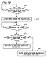
- the cursor 24 may be moved into the desired wedge 12 and a timing function may automatically select the wedge/item/value when a predetermined time has elapsed as best shown in Figure 7D .
- step S 130 it is determined whether a first selection is received for activating the radial control menu 10. If the menu activation command is received, the radial control menu 10 is displayed, a timer (not shown) is set, and the position cursor 24 is allowed to be moved to the appropriate wedge at step S 132. If the timer determines that the predetermined time has elapsed at step S 134, it is determined whether the cursor 24 is still located at the origin 20 of the menu 10 at step S 136. If the cursor 24 is located in the origin 20, the menu 10 is deactivated without making a selection at step S138. Otherwise, a new variable value is set based on the position of the position cursor 24 in the radial control menu 10 at step S 140.
- the predetermined time may be set to be short, for example, 1 second or less.
- the predetermined time may be adjustable by a user to meet a particular user's needs. For example, if the user is new to the radial control menu 10, the predetermined time may be set longer, while an experienced user that does not need to study the radial control menu 10 to make a selection may want a short predetermined time. Should the predetermined time elapse without the user having moved the cursor 24 into the wedge/item 12 to be selected, the radial control menu 10 would be deactivated so that the user can continue working or reactivate the menu 10 when ready to make a selection.
- an activation button may be held for displaying the menu 10 while the input device 22 (see Figure 9 ) is used to select or adjust the items/wedges.
- the menu 10 is deactivated when the activation button is released regardless of the position of the cursor 24 and regardless of whether a selection or adjustment has been made.
- Figure 8 shows a method of controlling variables using a radial control menu according to another embodiment of the present invention.
- the method of Figure 8 may be performed using the radial control menu 10 shown in Figure 2 .
- the method of Figure 8 will be described with reference to Figure 2 . It should be understood, however, that the method shown in Figure 8 can be applied to the radial menus of any of the embodiments described herein.
- the movable indicator(s) in steps S 151 to S 154 may refer to a cursor, a selectable movable indicator, a path tracing element, or a rubber band line.
- step S 150 a menu activation command is received at the input device 22.
- the radial control menu 10 is activated in the graphical user interface 26 at step S 152.
- the activation of the radial control menu 10 performed at step S152 includes retrieving current variable settings for the wedges 12 in the radial control menu 10 and displaying each wedge 12 including its own movable indicator 18.
- step S 154 the graphical user interface 26 enables the input device 22 (see Figure 9 ) to move the movable indicator(s) 18 between the boundaries 14 and 16 of the respective wedge(s) 12 to change the current values of the variables.
- the current values of the variables are updated based on the current distance between the boundaries 14 and 16 of the respective wedge(s) 12 and the movable indicator(s) 18 in step S 156.
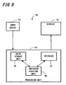
- a system 80 allows variables to be controlled using a radial control menu.
- the system 80 of Figure 9 will be described with reference to the radial control menu 10 of Figure 2 .
- the system 80 may be used with any of the above-described radial control menus and other variations thereof in a similar manner.
- the system 80 includes the display 32 which interacts with the graphical user interface 26 so that the user can manipulate the graphics on the display 32.
- the graphical user interface 26 runs on a processing unit 82 to display the radial control menu 10.
- the system 80 further includes the input device 22 to enable a user to interact with the graphical user interface 26.
- the processing unit 82 includes a value storage unit 84 for storing current values of at least one variable.
- the processing unit 82 also includes an indicator position unit 86 for determining the position of the movable indicator(s) 18 in the respective wedges 12 of the radial control menu 10.
- the indicator position unit 86 determines the new, updated value of the variable based on the new position of the movable indicator(s) 18 within the wedge 12. For example, the indicator position unit 86 may determine the new variable value based on the angular position of the movable indicator(s) 18 with respect to the boundaries 14 and 16 of the wedge 12. To this end, the indicator position unit 86 may include a storage unit (not shown), such as a lookup table, that stores a plurality of angular positions in one to one correspondence with variable values. Once the indicator position unit 86 determines the current, updated value of the variable, the indicator position unit 86 provides this value to the value storage unit 84 for storage.
- a storage unit not shown
- the indicator position unit 86 retrieves the current variable value stored in the value storage unit 84 and determines the appropriate position of the movable indicator(s) 18 within the respective wedge(s) 12. Accordingly, the radial control menu 10 is displayed by the graphical user interface 26 with the movable indicator(s) 18 positioned appropriately within the wedge(s) 12.
- the graphical user interface 26 runs on the processing unit 82 to allow a user to interact with the display 32 using the input device 22.
- the graphical user interface 26 accesses the value storage unit 84 and the indicator position unit 86 to allow the user to manipulate the radial control menu 10.
- the indicator position unit 86 is shown as being separate from the graphical user interface 26, it should be understood that the graphical user interface 26 may alternatively include the functionality of the indicator position unit 86.
- a digitizer tablet 88 may be used as the input device 22 shown in Figure 9 .
- the digitizer tablet 88 includes a tablet housing 90, a position detecting surface 92 defined by the tablet housing 90, and a pointing device 94 for interacting with the position detecting surface 92 so that the position of the pointing device 94 is detected by the digitizer tablet 88.
- the pointing device 94 may be a stylus, a mouse, a puck, or the like.
- the tablet housing 90 includes a button 96, which may be used to activate the radial menu(s) described above. Alternatively, a button 98 on the pointing device 94 may be used to activate the radial menu(s).
- the button 96 on the tablet housing 90 is used to activate the radial menu
- the button 98 on the pointing device 94 is used to make a selection in the radial menu.
- the pointing device 94 can be used on the position detecting surface 92 to move the cursor 24 in the wedge 12 of the radial control menu 10 (see Figure 2 ). Accordingly, setting values and/or selecting of menu items in the radial control menu 10 are performed efficiently and conveniently.
- the apparatus and methods of the various embodiments of the present invention can be implemented as software or computer readable recording medium running on a host application.
- the computer readable recording medium may be any data storage device that can store data which can be thereafter read by a computer system. Examples of the computer readable recording medium include read-only memory (ROM), random-access memory (RAM), CD-ROMs, flash memory, downloadable instructions, magnetic tapes, floppy disks, optical data storage devices, and carrier waves (such as data transmission through the Internet), among other things.
Landscapes
- Engineering & Computer Science (AREA)
- General Engineering & Computer Science (AREA)
- Theoretical Computer Science (AREA)
- Human Computer Interaction (AREA)
- Physics & Mathematics (AREA)
- General Physics & Mathematics (AREA)
- User Interface Of Digital Computer (AREA)
- Position Input By Displaying (AREA)
- Digital Computer Display Output (AREA)
Claims (13)
- Computersystem, welches ausgebildet ist zum Anzeigen einer graphischen Nutzerschnittstelle (26) zum Anzeigen von Handlungen eines Eingabegerätes auf einer Anzeige, wobei die graphische Nutzerschnittstelle (26) folgendes aufweist:ein radiales Menü mit:einem Ursprung (20), der an einem Mittelpunkt des radialen Menüs angeordnet ist, undzumindest einem ersten Keilabschnitt (12), der ein Gebiet definiert, welches sich nach außen von dem Ursprung (20) erstreckt, wobei der erste Keilabschnitt (12) zu einer Variable gehört, die auf einen Wert gesetzt werden kann zwischen einem vorbestimmten Minimalwert und einem vorbestimmten Maximalwert; undeinen Cursor (24) zum Anzeigen einer gegenwärtigen Position des Eingabegerätes auf der Anzeige,dadurch gekennzeichnet, dassdas radiale Menü ferner zumindest eine erste Variablen-Einstelleinrichtung aufweist, die in dem ersten Keilabschnitt (12) angeordnet ist, wobei die erste Variablen-Einstelleinrichtung bezüglich eines Winkels durch den Cursor (24) um den Ursprung herum (20) innerhalb des ersten Keilabschnittes (12) bewegbar ist, um den gegenwärtigen Wert der Variable basierend auf der Winkelposition der zumindest einen Variablen-Einstelleinrichtung innerhalb des ersten Keilabschnittes (12) auszuwählen,wobei die erste Variablen-Einstellrichtung eine bewegbare Linie (18, 19) aufweist, die von dem Ursprung (20) des radialen Menüs sich erstreckt, wobei die bewegbare Linie (18, 19) ein erstes Ende, welches sich am Nahesten zum Ursprung (20) befindet, und ein zweites Ende, welches sich am Weitesten weg von dem Ursprung (20) befindet, aufweist, wobei das zweite Ende einer Position des Cursors (24) entspricht, so dass eine Bewegung des Cursors eine Winkelposition und/oder eine Länge der bewegbaren Linie (18, 19) ändert.
- Computersystem nach Anspruch 1, wobei der erste Keilabschnitt (22) einen Anzeiger für den gegenwärtigen Wert aufweist, wobei der Anzeiger für den gegenwärtigen Wert angezeigt wird in Antwort darauf, dass der Cursor (24) in ein Gebiet, welches durch den Keilabschnitt (12) begrenzt wird, sich hineinbewegt oder sich innerhalb des Gebietes bewegt.
- Computersystem nach Anspruch 1 oder 2, wobei der erste Keilabschnitt folgendes aufweist:eine Minimalgrenze (16), die durch eine erste radiale Grenze des ersten Keilabschnittes (12) definiert wird, wobei die Minimalgrenze (16) den vorbestimmten Minimalwert der Variable darstellt; undeine Maximalgrenze (14), die gegenüberliegend zu der Minimalgrenze ist, wobei die Maximalgrenze (14) einen zweiten radialen Rand des ersten Keilabschnittes definiert und den vorbestimmten Maximalwert der Variable darstellt,wobei der Cursor (24) bezüglich eines Winkels bewegbar ist zwischen der maximalen und der minimalen Grenze (14, 16), um den gegenwärtigen Wert der Variable zu ändern.
- Computersystem nach Anspruch 1, wobei die erste Variablen-Einstelleinrichtung einen Pfadnachverfolger aufweist, der durch ein Folgen eines Pfades des Cursors innerhalb des ersten Keilabschnittes gezeichnet wird (12).
- Computersystem nach einem der vorhergehenden Ansprüche, wobei das radiale Menü aktiviert wird in einem begrenzten Modus, in welchen der erste Keilabschnitt (12) eine äußere Grenze hat, die gegenüberliegend zu dem Ursprung (20) des radialen Menüs ist, wenn eine erste Eingabe empfangen wird, und das radiale Menü aktiviert wird in einem unbegrenzten Modus, in welchem der erste Keilabschnitt (12) keine definierte äußere Grenze gegenüberliegend zu dem Ursprung (20) des radialen Menüs hat, wenn eine zweite Eingabe empfangen wird, wobei die zweite Eingabe unterschiedlich ist von der ersten Eingabe.
- Computersystem nach einem der vorhergehenden Ansprüche, wobei der erste Keilabschnitt (12) einen nicht auswählbaren Bereich und einen auswählbaren Bereich aufweist, wobei der auswählbare Bereich eine größere Bogenlänge hat.
- Computersystem nach einem der vorhergehenden Ansprüche, wobei das Menü folgendes aufweist:zumindest einen Keilabschnitt, der eine Steuervariable darstellt, wobei der Keilabschnitt eine maximale radiale Grenze (14) aufweist, die einen vorbestimmten Maximalwert der Steuervariable darstellt und eine minimale radiale Grenze (16) aufweist, die einen vorbestimmten Minimalwert der Steuervariable darstellt, wobei die radialen Grenzen (14, 16) sich nach außen von dem Ursprung (20) des Menüs aus erstrecken;zumindest einen bewegbaren Linienindikator (19), der von dem Ursprung (20) des Menüs sich in den Keilabschnitt erstreckt, wobei der Linienindikator eine einstellbare Winkelposition aufweist zum Selektieren eines Wertes einer Steuervariable zwischen den vorbestimmten Maximal- und Minimalwerten, wobei der Wert, der für die Steuervariable ausgewählt wird, bestimmt wird in Bezug auf den vorbestimmten Maximal- und Minimalwerten durch ein Anteil einer Winkelentfernung zwischen dem Linienindikator und der maximalen und der minimalen radialen Grenzen (14, 16).
- Verfahren zum Steuern und/oder Darstellen eines Wertes von zumindest einer Variable, die gesetzt werden kann auf einen Wert zwischen einem vorbestimmten Minimalwert und einem vorbestimmten Maximalwert unter Nutzung eines Eingabegerätes, welches operativ zu einer graphischen Nutzerschnittstelle (26) gehört, die einen Cursor (24) aufweist zum Anzeigen einer gegenwärtigen Position des Eingabegeräts, wobei das Verfahren folgende Schritte aufweist:Aktivieren eines radialen Menüs in der graphischen Nutzerschnittstelle (26) in Antwort auf einen Menüaktivierungsbefehl, wobei das radiale Menü einen Ursprung (20) aufweist und zumindest einen ersten Keilabschnitt (12), der zu der Variable gehört und sich von dem Ursprung (20) aus erstreckt, so dass der Cursor innerhalb des ersten Keilabschnittes (12) bewegbar ist zum Selektieren eines gegenwärtigen Wertes der Variable basierend auf der Winkelposition des Cursors (20) um den Ursprung herum, wobei das radiale Menü weiter zumindest eine erste Variablen-Einstelleinrichtung aufweist, die in dem ersten Keilabschnitt (12) angeordnet ist, wobei die erste Variablen-Einstelleinrichtung winkelmäßig bewegbar ist durch den Cursor (24) um den Ursprung (20) herum innerhalb des ersten Keilabschnittes (12), um den gegenwärtigen Wert der Variable basierend auf der Winkelposition der ersten Variablen-Einstelleinrichtung zu selektieren, und zwar innerhalb des ersten Keilabschnittes (12), wobei die erste Variablen-Einstelleinrichtung eine bewegbare Linie (18, 19) aufweist, die von dem Ursprung (20) des radialen Menüs sich erstreckt, wobei die bewegbare Linie (18, 19) ein erstes Ende, welches sich am Nahesten zu dem Ursprung (20) befindet, und ein zweites Ende, welches sich am Weitesten weg von dem Ursprung (20) befindet, aufweist, wobei das zweite Ende einer Position des Cursors (24) entspricht,gekennzeichnet durchEmpfangen eines Bewegungsbefehls über das Eingabegerät, wobei der Bewegungsbefehl den Cursor (24) innerhalb des ersten Keilabschnitts (12) bewegt, wobei die Bewegung des Cursors (24) die Winkelposition und/oder Länge der bewegbaren Linie (18, 19) ändert, undÄndern des gegenwärtigen Wertes der Variable, um die geänderte Winkelposition der bewegbaren Linie (18, 19) durch die Bewegung des Cursors (24) um den Ursprung (20) herum darzustellen und den gegenwärtigen Wert der Variable anzuzeigen.
- Verfahren nach Anspruch 8, wobei
die Aktivierung des radialen Menüs, der Empfang des Bewegungskommandos und das Ändern des gegenwärtigen Wertes durch eine Doppeltastenauswahl von zumindest einer Taste, die zu dem Eingabegerät gehört, ausgeführt werden, wobei eine erste Tastenauswahl bewirkt, dass das radiale Menü angezeigt wird und eine zweite Tastenauswahl bewirkt, dass die erste Variablen-Einstelleinrichtung ausgewählt und/oder bewegt wird. - Verfahren nach Anspruch 8 oder 9, wobei das radiale Steuermenü zu einem Eingabegerät gehört, welches zumindest eine Taste aufweist, die dazu gehörig ist und eine Anzeige aufweist, die den Cursor (24) aufweist, wobei das Verfahren folgendes umfasst:Empfangen einer ersten Auswahl von zumindest einer Taste des Eingabegerätes;Darstellen des radialen Menüs auf der Anzeige in Antwort auf die erste Auswahl, wobei das radiale Steuermenü einen Ursprung (20) an einem Zentrum davon aufweist und zumindest einen Keilabschnitt (12) aufweist, der von dem Ursprung sich erstreckt, wobei das radiale Menü dargestellt wird, so dass der Ursprung (20) davon einer Position des Cursors auf der Anzeige entspricht;Bewegen des Eingabegeräts, um den Cursor (24) in zumindest einem Keilabschnitt (12) zu bewegen;Bestimmen eines gegenwärtigen Wertes der Variable basierend auf einer Winkelposition des Cursors (24) in Bezug auf den Ursprung (20) und Darstellen des gegenwärtigen Wertes der Variable in Bezug auf den zumindest einen Winkelabschnitt (12); undEmpfangen einer zweiten Auswahl der zumindest einen Taste zum Setzen des Wertes, der gegenwärtig dargestellt wird als den Wert der Variable.
- Verfahren nach einem der Ansprüche 8 bis 10, wobei das Eingabegerät einen Digitalisierer-Tablet aufweist mit zumindest einer ersten Taste und einem dazugehörigen Anzeigegerät mit zumindest einer zweiten Taste, wobei die erste Auswahl ein Auswählen der zumindest ersten Taste des Digitalisierer-Tablets umfasst und die zweite Auswahl ein Selektieren der zumindest einen zweiten Taste des Zeigergerätes umfasst.
- Verfahren nach Anspruch 10, wobei, wenn vor der zweiten Auswahl, der Cursor aus dem zumindest einen Keilabschnitt bewegt wird, in Antwort darauf der gegenwärtige Wert der Variable gelöscht wird von der Anzeige.
- Computerlesbares Medium mit ausführbarem Code, um ein Verfahren nach einem der Ansprüche 8 bis 12 auszuführen für eine Steuerung und/oder Darstellung eines Wertes von zumindest einer Variable, die gesetzt werden kann auf einen Wert zwischen einem vorbestimmten Minimalwert und einem vorbestimmen Maximalwert unter Nutzung eines Eingabegerätes, welches operativ zu einer graphischen Nutzerschnittstelle (26) gehört.
Applications Claiming Priority (1)
| Application Number | Priority Date | Filing Date | Title |
|---|---|---|---|
| US12/106,688 US7941765B2 (en) | 2008-01-23 | 2008-04-21 | System and method of controlling variables using a radial control menu |
Publications (3)
| Publication Number | Publication Date |
|---|---|
| EP2083350A2 EP2083350A2 (de) | 2009-07-29 |
| EP2083350A3 EP2083350A3 (de) | 2013-01-16 |
| EP2083350B1 true EP2083350B1 (de) | 2014-08-06 |
Family
ID=40590406
Family Applications (1)
| Application Number | Title | Priority Date | Filing Date |
|---|---|---|---|
| EP09000857.4A Ceased EP2083350B1 (de) | 2008-04-21 | 2009-01-22 | Radialsteuerungsmenü, grafische Nutzerschnittstelle, Verfahren zur Variablensteuerung und computerlesbares Medium zur Durchführung des Verfahrens |
Country Status (3)
| Country | Link |
|---|---|
| EP (1) | EP2083350B1 (de) |
| JP (1) | JP5219152B2 (de) |
| CN (1) | CN101566910B (de) |
Families Citing this family (16)
| Publication number | Priority date | Publication date | Assignee | Title |
|---|---|---|---|---|
| KR20130124502A (ko) | 2010-10-01 | 2013-11-14 | 톰슨 라이센싱 | 사용자 인터페이스의 내비게이션 시스템 및 방법 |
| CN102915173B (zh) * | 2011-08-04 | 2015-11-25 | 腾讯科技(深圳)有限公司 | 菜单实现方法和系统 |
| JP5852893B2 (ja) * | 2012-01-25 | 2016-02-03 | 株式会社アマダホールディングス | ワーク加工の角度を入力設定する加工機および加工機における角度入力設定方法 |
| US20140078063A1 (en) * | 2012-09-18 | 2014-03-20 | Microsoft Corporation | Gesture-initiated keyboard functions |
| CN104077036B (zh) * | 2013-03-27 | 2017-11-10 | 苏州精易会信息技术有限公司 | 一种分类导航的下拉菜单设计实现方法 |
| JP2015049861A (ja) | 2013-09-04 | 2015-03-16 | Necパーソナルコンピュータ株式会社 | 情報処理装置、制御方法、及びプログラム |
| EP2887196B1 (de) * | 2013-12-20 | 2020-08-19 | Dassault Systèmes | Computerimplementiertes Verfahren zum Konfigurieren eines Werkzeugs mit mindestens einem Zeigerelement auf einem Bildschirm |
| JP5707519B1 (ja) * | 2014-02-05 | 2015-04-30 | 日本電信電話株式会社 | 入力装置、入力方法及びプログラム |
| EP3040832A1 (de) | 2014-12-29 | 2016-07-06 | Dassault Systèmes | Einstellung eines Parameters |
| EP3040838B1 (de) * | 2014-12-29 | 2021-04-21 | Dassault Systèmes | Einstellung eines Parameters |
| EP3040831A1 (de) | 2014-12-29 | 2016-07-06 | Dassault Systèmes | Einstellung eines Parameters |
| JP6565256B2 (ja) * | 2015-03-25 | 2019-08-28 | コニカミノルタ株式会社 | 表示装置、画像処理装置及びプログラム |
| JP6915492B2 (ja) * | 2017-10-11 | 2021-08-04 | トヨタ自動車株式会社 | 表示制御装置 |
| US10898801B2 (en) * | 2019-06-03 | 2021-01-26 | Valve Corporation | Selecting properties using handheld controllers |
| US10977836B2 (en) * | 2019-07-31 | 2021-04-13 | L'oreal | Color wheel interface |
| CN113589994A (zh) * | 2021-07-30 | 2021-11-02 | 恒生电子股份有限公司 | 导航菜单的显示控制方法、装置、设备及存储介质 |
Family Cites Families (7)
| Publication number | Priority date | Publication date | Assignee | Title |
|---|---|---|---|---|
| CA2069118A1 (en) * | 1991-09-16 | 1993-03-17 | Craig Henry Becker | Multiple action icon |
| US5790820A (en) * | 1995-06-07 | 1998-08-04 | Vayda; Mark | Radial graphical menuing system |
| US5995079A (en) * | 1997-04-04 | 1999-11-30 | Avid Technology, Inc. | Method for controlling a variable of a dialog box with cursor movement |
| US7286115B2 (en) * | 2000-05-26 | 2007-10-23 | Tegic Communications, Inc. | Directional input system with automatic correction |
| JP4390371B2 (ja) * | 2000-06-20 | 2009-12-24 | シャープ株式会社 | メニュー選択装置およびその方法、ならびにメニュー選択プログラムを記録したコンピュータ読取可能な記録媒体 |
| WO2006056243A1 (en) * | 2004-11-24 | 2006-06-01 | 3Dconnexion Holding Sa | Setting input values with group-wise arranged menu items |
| US20100188268A1 (en) * | 2006-09-01 | 2010-07-29 | Nokia Corporation | Touchpad |
-
2009
- 2009-01-20 JP JP2009010360A patent/JP5219152B2/ja not_active Expired - Fee Related
- 2009-01-22 CN CN200910009904.XA patent/CN101566910B/zh active Active
- 2009-01-22 EP EP09000857.4A patent/EP2083350B1/de not_active Ceased
Also Published As
| Publication number | Publication date |
|---|---|
| JP2009266203A (ja) | 2009-11-12 |
| EP2083350A2 (de) | 2009-07-29 |
| CN101566910A (zh) | 2009-10-28 |
| JP5219152B2 (ja) | 2013-06-26 |
| CN101566910B (zh) | 2014-06-11 |
| EP2083350A3 (de) | 2013-01-16 |
Similar Documents
| Publication | Publication Date | Title |
|---|---|---|
| EP2083350B1 (de) | Radialsteuerungsmenü, grafische Nutzerschnittstelle, Verfahren zur Variablensteuerung und computerlesbares Medium zur Durchführung des Verfahrens | |
| US7941765B2 (en) | System and method of controlling variables using a radial control menu | |
| US7735020B2 (en) | Method and apparatus for determining font attributes | |
| EP2049981B1 (de) | Granuläres grafikbenutzerschnittstellenelement | |
| US6057844A (en) | Drag operation gesture controller | |
| US9465535B2 (en) | Method for operating virtual adjusting button | |
| US6731315B1 (en) | Method for selecting display parameters of a magnifiable cursor | |
| US9459791B2 (en) | Radial menu selection | |
| JP4649111B2 (ja) | ソリッドステートオブジェクト位置検出機の閉ループセンサ | |
| EP0498082B1 (de) | Vorrichtung zur interaktiven Behandlung von Objekten | |
| US7071919B2 (en) | Positional scrolling | |
| EP1993026A2 (de) | Vorrichtung, Verfahren und computerlesbares Medium zur Abbildung eines Grafiktabletts auf einer zugehörigen Anzeige | |
| US8826181B2 (en) | Moving radial menus | |
| US7398477B2 (en) | Spiral scrollbar | |
| US20060048069A1 (en) | Display apparatus and method for displaying screen where dragging and dropping of object can be executed and program stored in computer-readable storage medium | |
| US20120182296A1 (en) | Method and interface for man-machine interaction | |
| US20090327955A1 (en) | Selecting Menu Items | |
| US20180349005A1 (en) | Slider Manipulation with Precision Alteration | |
| US20060288312A1 (en) | Information processing apparatus and recording medium storing program | |
| WO2003104965A2 (en) | Computer navigation | |
| EP2674837A9 (de) | Stift mit Steuerring-Benutzerschnittstelle | |
| EP2629190A1 (de) | Elektronische Vorrichtung, Verfahren zur Steuerung davon und computerlesbares Speichermedium | |
| EP3545524A1 (de) | Steuergeräte zur manipulation und visualisierung von gesundheitsinformationen | |
| US11681414B2 (en) | Command display control method, computer-readable medium and apparatus | |
| US20090249243A1 (en) | Method for controlling information display |
Legal Events
| Date | Code | Title | Description |
|---|---|---|---|
| PUAI | Public reference made under article 153(3) epc to a published international application that has entered the european phase |
Free format text: ORIGINAL CODE: 0009012 |
|
| AK | Designated contracting states |
Kind code of ref document: A2 Designated state(s): AT BE BG CH CY CZ DE DK EE ES FI FR GB GR HR HU IE IS IT LI LT LU LV MC MK MT NL NO PL PT RO SE SI SK TR |
|
| AX | Request for extension of the european patent |
Extension state: AL BA RS |
|
| RAP1 | Party data changed (applicant data changed or rights of an application transferred) |
Owner name: WACOM CO., LTD. |
|
| PUAL | Search report despatched |
Free format text: ORIGINAL CODE: 0009013 |
|
| AK | Designated contracting states |
Kind code of ref document: A3 Designated state(s): AT BE BG CH CY CZ DE DK EE ES FI FR GB GR HR HU IE IS IT LI LT LU LV MC MK MT NL NO PL PT RO SE SI SK TR |
|
| AX | Request for extension of the european patent |
Extension state: AL BA RS |
|
| RIC1 | Information provided on ipc code assigned before grant |
Ipc: G06F 3/048 20130101AFI20121207BHEP |
|
| 17P | Request for examination filed |
Effective date: 20130716 |
|
| RBV | Designated contracting states (corrected) |
Designated state(s): AT BE BG CH CY CZ DE DK EE ES FI FR GB GR HR HU IE IS IT LI LT LU LV MC MK MT NL NO PL PT RO SE SI SK TR |
|
| AKX | Designation fees paid |
Designated state(s): DE GB |
|
| 17Q | First examination report despatched |
Effective date: 20130823 |
|
| GRAP | Despatch of communication of intention to grant a patent |
Free format text: ORIGINAL CODE: EPIDOSNIGR1 |
|
| INTG | Intention to grant announced |
Effective date: 20140224 |
|
| RIN1 | Information on inventor provided before grant (corrected) |
Inventor name: FLECK, DAVE C. Inventor name: STRAUB, BEN Inventor name: NORTON, V. THANE III |
|
| GRAS | Grant fee paid |
Free format text: ORIGINAL CODE: EPIDOSNIGR3 |
|
| GRAA | (expected) grant |
Free format text: ORIGINAL CODE: 0009210 |
|
| AK | Designated contracting states |
Kind code of ref document: B1 Designated state(s): DE GB |
|
| REG | Reference to a national code |
Ref country code: GB Ref legal event code: FG4D |
|
| REG | Reference to a national code |
Ref country code: DE Ref legal event code: R096 Ref document number: 602009025753 Country of ref document: DE Effective date: 20140918 |
|
| REG | Reference to a national code |
Ref country code: DE Ref legal event code: R097 Ref document number: 602009025753 Country of ref document: DE |
|
| PLBE | No opposition filed within time limit |
Free format text: ORIGINAL CODE: 0009261 |
|
| STAA | Information on the status of an ep patent application or granted ep patent |
Free format text: STATUS: NO OPPOSITION FILED WITHIN TIME LIMIT |
|
| 26N | No opposition filed |
Effective date: 20150507 |
|
| PGFP | Annual fee paid to national office [announced via postgrant information from national office to epo] |
Ref country code: GB Payment date: 20230119 Year of fee payment: 15 Ref country code: DE Payment date: 20220620 Year of fee payment: 15 |
|
| P01 | Opt-out of the competence of the unified patent court (upc) registered |
Effective date: 20230907 |
|
| REG | Reference to a national code |
Ref country code: DE Ref legal event code: R119 Ref document number: 602009025753 Country of ref document: DE |
|
| GBPC | Gb: european patent ceased through non-payment of renewal fee |
Effective date: 20240122 |
|
| PG25 | Lapsed in a contracting state [announced via postgrant information from national office to epo] |
Ref country code: DE Free format text: LAPSE BECAUSE OF NON-PAYMENT OF DUE FEES Effective date: 20240801 |
|
| PG25 | Lapsed in a contracting state [announced via postgrant information from national office to epo] |
Ref country code: GB Free format text: LAPSE BECAUSE OF NON-PAYMENT OF DUE FEES Effective date: 20240122 |
|
| PG25 | Lapsed in a contracting state [announced via postgrant information from national office to epo] |
Ref country code: GB Free format text: LAPSE BECAUSE OF NON-PAYMENT OF DUE FEES Effective date: 20240122 Ref country code: DE Free format text: LAPSE BECAUSE OF NON-PAYMENT OF DUE FEES Effective date: 20240801 |