EP2083256A1 - Method for agitating liquid material by using crystal oscillator - Google Patents
Method for agitating liquid material by using crystal oscillator Download PDFInfo
- Publication number
- EP2083256A1 EP2083256A1 EP07832048A EP07832048A EP2083256A1 EP 2083256 A1 EP2083256 A1 EP 2083256A1 EP 07832048 A EP07832048 A EP 07832048A EP 07832048 A EP07832048 A EP 07832048A EP 2083256 A1 EP2083256 A1 EP 2083256A1
- Authority
- EP
- European Patent Office
- Prior art keywords
- crystal oscillator
- quartz crystal
- frequency
- agitation
- agitating
- Prior art date
- Legal status (The legal status is an assumption and is not a legal conclusion. Google has not performed a legal analysis and makes no representation as to the accuracy of the status listed.)
- Granted
Links
Images


Classifications
-
- G—PHYSICS
- G01—MEASURING; TESTING
- G01N—INVESTIGATING OR ANALYSING MATERIALS BY DETERMINING THEIR CHEMICAL OR PHYSICAL PROPERTIES
- G01N29/00—Investigating or analysing materials by the use of ultrasonic, sonic or infrasonic waves; Visualisation of the interior of objects by transmitting ultrasonic or sonic waves through the object
- G01N29/02—Analysing fluids
- G01N29/022—Fluid sensors based on microsensors, e.g. quartz crystal-microbalance [QCM], surface acoustic wave [SAW] devices, tuning forks, cantilevers, flexural plate wave [FPW] devices
-
- B—PERFORMING OPERATIONS; TRANSPORTING
- B01—PHYSICAL OR CHEMICAL PROCESSES OR APPARATUS IN GENERAL
- B01F—MIXING, e.g. DISSOLVING, EMULSIFYING OR DISPERSING
- B01F31/00—Mixers with shaking, oscillating, or vibrating mechanisms
- B01F31/80—Mixing by means of high-frequency vibrations above one kHz, e.g. ultrasonic vibrations
- B01F31/86—Mixing by means of high-frequency vibrations above one kHz, e.g. ultrasonic vibrations with vibration of the receptacle or part of it
-
- B—PERFORMING OPERATIONS; TRANSPORTING
- B01—PHYSICAL OR CHEMICAL PROCESSES OR APPARATUS IN GENERAL
- B01F—MIXING, e.g. DISSOLVING, EMULSIFYING OR DISPERSING
- B01F33/00—Other mixers; Mixing plants; Combinations of mixers
- B01F33/30—Micromixers
-
- G—PHYSICS
- G01—MEASURING; TESTING
- G01N—INVESTIGATING OR ANALYSING MATERIALS BY DETERMINING THEIR CHEMICAL OR PHYSICAL PROPERTIES
- G01N29/00—Investigating or analysing materials by the use of ultrasonic, sonic or infrasonic waves; Visualisation of the interior of objects by transmitting ultrasonic or sonic waves through the object
- G01N29/02—Analysing fluids
- G01N29/036—Analysing fluids by measuring frequency or resonance of acoustic waves
-
- G—PHYSICS
- G01—MEASURING; TESTING
- G01N—INVESTIGATING OR ANALYSING MATERIALS BY DETERMINING THEIR CHEMICAL OR PHYSICAL PROPERTIES
- G01N29/00—Investigating or analysing materials by the use of ultrasonic, sonic or infrasonic waves; Visualisation of the interior of objects by transmitting ultrasonic or sonic waves through the object
- G01N29/22—Details, e.g. general constructional or apparatus details
- G01N29/222—Constructional or flow details for analysing fluids
Definitions
- the present invention relates to a method for agitating a liquefied material for use in assaying a trace substance contained in the liquefied material.
- QCM quadratz crystal microbalance
- Assaying with QCM is carried out by putting a buffer solution in contact with a quartz crystal oscillator electrode and adding a solution containing a sample as a subject to be assayed to the buffer solution, to measure the frequency variation occurring due to the binding of the sample to a substance immobilized on the quartz crystal oscillator electrode.
- the sample may happen to be precipitated on the bottom of the buffer solution or the sample may happen to float on the liquid surface so that the solution cannot be mixed together.
- a method for solving the problems comprising placing an agitation rod in a container with a buffer solution injected therein and vibrating the solution therein along the upward and downward directions mechanically or rotating the solution (for example, patent reference 1). Since a certain amount of the solution is needed so as to enable agitation of the solution by the method, however, the solution of a trace volume cannot be agitated sufficiently, disadvantageously. Because the solution cannot be agitated sufficiently, then, it is hard to carry out assays at high precision.
- the method for agitating a liquefied material using a quartz crystal oscillator is characterized in that in vibrating the quartz crystal oscillator at a given frequency and measuring the variation of the frequency due to a substance in contact with the quartz crystal oscillator, in accordance with the invention, the quartz crystal oscillator is vibrated at other frequency different from the given frequency and equal to or higher than the fundamental vibration frequency to agitate a liquid containing the substance.
- the method for agitating a liquefied material using a quartz crystal oscillator according to claim 1 or 2 is characterized in that the quartz crystal oscillator is vibrated at a state fixed at the other frequency or a frequency sweeping within a range of ⁇ 100 kHz around the center of the other frequency, during the time of agitation.
- the method for agitating a liquefied material using a quartz crystal oscillator according to any of claims 1 through 3 is characterized in that the electric power applied to the quartz crystal oscillator during the time of agitation is preset to 10-fold or more the electric power during the time of measurement.
- N 3, 5, 7,...) vibration frequency during the time of measurement.
- the method for agitating a liquefied material using a quartz crystal oscillator according to any one of claims 1 through 5 is characterized in that the agitation is done before the measurement or the agitation is done between individual measurements when the measurement is continuously carried out.
- no specific agitation unit is separately arranged during QCM measurement. Additionally, even a trace amount of a liquefied material for use in the measurement can be agitated. In accordance with the invention, still additionally, a liquefied material containing a trace amount of a sample can be agitated so sufficiently that measurement at a higher precision can be achieved.
- any quartz crystal oscillators including quartz crystal oscillators for general use in QCM can be used with no specific limitation as the quartz crystal oscillator in accordance with the invention.
- agitation is done at other frequency different from a given frequency for use in measurement and equal to or higher than the fundamental vibration frequency of the quartz crystal oscillator.
- the other frequency is preferably selected to be; 27MHz or 135 MHz in case that the frequency for measurement is 81 MHz which is the 3rd harmonic frequency vibration frequency; and 81 MHz in case that 27MHz is used as the frequency for measurement.
- the fundamental vibration frequency or the sub-vibration frequency is preferably selected.
- the frequency for use in measurement may be the fundamental vibration frequency, however, an Nth harmonic vibration frequency which is less influenced by compressional wave is preferably used.
- the quartz crystal oscillator is continuously vibrated at any one of the frequencies or the quartz crystal oscillator is vibrated at a frequency sweeping within a range of ⁇ 100 kHz around the center of any one of the frequencies.
- the quartz crystal oscillator is applied with a load of an electric power of about 1 mW to oscillate and then the variation of the frequency is measured or the change of resonance frequency is measured by using a network analyzer or an impedance analyzer.
- Agitation is preferably carried out at an electric power ranging from 10-to 100-fold the electric power loaded on the quartz crystal oscillator during measurement.
- the measured frequency may sometimes get unstable possibly involving a big noise, and therefore, it is preferable that agitation and measurement are done alternately or agitation is done before measurement.
- the frequency may also be measured, using a network analyzer or an impedance analyzer or by a measurement method with a frequency counter during direct oscillation of the quartz crystal oscillator. During the use of a network analyzer, the frequency can be measured with or without use of ⁇ circuit. Quartz crystal oscillators for use in measurement and agitation may be set at not only one channel but also multi channels.
- the quartz crystal oscillator for use in accordance with the invention includes, for example, a quartz crystal oscillator of the construction shown in Fig.1 .
- the quartz crystal oscillator is generally used for QCM, where counter electrodes 3, 3 are arranged on both the sides of a quartz crystal plate 1.
- the quartz crystal plate 1 is about 60 ⁇ m in thickness and about 8.9 mm in diameter (Rc).
- the counter electrode 3 is made of, for example, gold and of a diameter (Re) of about 2.5 mm.
- the diameter of the electrode 2 is about 8 mm, larger than the electrode of the general quartz crystal oscillator in the construction described above. The reason is that heat generated during agitation can be dispersed to suppress temperature increase of the quartz crystal oscillator and the solution, allowing the measurement at a lower noise.
- the electrode may be formed on any one or both of the surface and back faces.
- a method for arranging a solution 4 on the gold electrode 2 as shown in Fig.3 a method for arranging the quartz crystal oscillator on the bottom of a container 5 and injecting a trace volume (about 500 ⁇ l or less) of the solution 4 above the quartz crystal oscillator as shown in Fig.5 , or a flow cell may be used but without any limitation.
- the quartz crystal oscillator was set to vibrate at a frequency around 81 MHz which is the 3rd harmonic frequency frequency; in case of enforcing agitation, the quartz crystal oscillator was set to vibrate at a frequency around the fundamental frequency (27 MHz) or around the sub-vibration frequency of the fundamental frequency of the fundamental wave (scanning within a range of ⁇ 100 kHz).
- the input electric power was 2 mW for the measurement and 200 mW for the agitation.
- the relay #1 was controlled so as to repeat ON and OFF modes every one second, while the relay #2 was controlled so as to repeat taking ON mode for 300 milliseconds simultaneously with the start of the OFF mode of the relay #1 and then taking OFF mode thereafter.
- Figs. 8 and 9 show the measurement results with agitation under controls of the relays #1 and #2 and without agitation, respectively.
- Fig.8 shows that in the case with agitation, the variation of the frequency as measured after the N-avidin injection was on a gradually decreasing curve and the time required for the frequency to be stabilized was shorter compared with the case with no agitation.
- the frequency measured was decreased by -1000 Hz immediately after the N-avidin injection and then at a more or less leveled-off state and subsequently, decreased. This indicates that the frequency measured requires a time for stabilization in the case with no agitation.
- circuit composition example described above is just an exemplification. Even a circuit using a frequency counter 11 so as to oscillate the quartz crystal oscillator instead of the network analyzer as shown in Fig.7 can also be used.
- the invention can be utilized in a wide variety of fields for assaying interactions between biological substances such as DNA and proteins or assaying antigen-antibody reactions.
Landscapes
- Physics & Mathematics (AREA)
- Chemical & Material Sciences (AREA)
- General Physics & Mathematics (AREA)
- Immunology (AREA)
- Health & Medical Sciences (AREA)
- Analytical Chemistry (AREA)
- Biochemistry (AREA)
- General Health & Medical Sciences (AREA)
- Acoustics & Sound (AREA)
- Life Sciences & Earth Sciences (AREA)
- Pathology (AREA)
- Chemical Kinetics & Catalysis (AREA)
- Sampling And Sample Adjustment (AREA)
- Piezo-Electric Or Mechanical Vibrators, Or Delay Or Filter Circuits (AREA)
- Measurement Of Mechanical Vibrations Or Ultrasonic Waves (AREA)
- Oscillators With Electromechanical Resonators (AREA)
Abstract
Description
- The present invention relates to a method for agitating a liquefied material for use in assaying a trace substance contained in the liquefied material.
- QCM (quartz crystal microbalance) is utilized for assaying interactions between biological substances such as DNA and proteins and for assays using antigen-antibody reactions.
Assaying with QCM is carried out by putting a buffer solution in contact with a quartz crystal oscillator electrode and adding a solution containing a sample as a subject to be assayed to the buffer solution, to measure the frequency variation occurring due to the binding of the sample to a substance immobilized on the quartz crystal oscillator electrode.
In that case, for example, the sample may happen to be precipitated on the bottom of the buffer solution or the sample may happen to float on the liquid surface so that the solution cannot be mixed together. Consequently, the solution cannot reach a constant final concentration, which causes inaccurate assays of the binding amount or causes no success in the binding rate analysis.
As one method for solving the problems, there is provided for example a method comprising placing an agitation rod in a container with a buffer solution injected therein and vibrating the solution therein along the upward and downward directions mechanically or rotating the solution (for example, patent reference 1).
Since a certain amount of the solution is needed so as to enable agitation of the solution by the method, however, the solution of a trace volume cannot be agitated sufficiently, disadvantageously. Because the solution cannot be agitated sufficiently, then, it is hard to carry out assays at high precision.
Due to the vibration of the quartz crystal oscillator with an electric power applied during assaying, furthermore, waves such as share wave and compressional wave generate. In case of an AT-cut quartz crystal oscillator of 27 MHz, share wave is reduced at a distance of about 100 nm from the surface of the quartz crystal oscillator, so that such wave cannot be used for agitation. It has been revealed experimentally that compressional wave itself cannot agitate liquefied materials. -
- Patent reference 1:
JP-A-2002-310872 - So as to solve the problems described above, it is an object of the invention to provide an agitation method for sufficiently agitating a mixture of a solution such as buffer solution and a material to be detected, with no need of any unit specified for agitation, for measurements using a quartz crystal oscillator.
- So as to solve the problems described above, the inventor made investigations to get the following findings.
According toclaim 1, the method for agitating a liquefied material using a quartz crystal oscillator is characterized in that in vibrating the quartz crystal oscillator at a given frequency and measuring the variation of the frequency due to a substance in contact with the quartz crystal oscillator, in accordance with the invention, the quartz crystal oscillator is vibrated at other frequency different from the given frequency and equal to or higher than the fundamental vibration frequency to agitate a liquid containing the substance.
According toclaim 2, the method for agitating a liquefied material according toclaim 1 is characterized in that the other frequency is the fundamental vibration frequency, the sub-vibration frequency or an Nth harmonic (N = 3, 5, 7, ...) vibration frequency.
According toclaim 3, the method for agitating a liquefied material using a quartz crystal oscillator according toclaim
According toclaim 4, still further, the method for agitating a liquefied material using a quartz crystal oscillator according to any ofclaims 1 through 3 is characterized in that the electric power applied to the quartz crystal oscillator during the time of agitation is preset to 10-fold or more the electric power during the time of measurement.
According toclaim 5, the method for agitating a liquefied material using a quartz crystal oscillator according to any one ofclaims 1 through 4 is characterized in that the quartz crystal oscillator is vibrated at an Nth harmonic (N = 3, 5, 7,...) vibration frequency during the time of measurement.
According toclaim 6, the method for agitating a liquefied material using a quartz crystal oscillator according to any one ofclaims 1 through 5 is characterized in that the agitation is done before the measurement or the agitation is done between individual measurements when the measurement is continuously carried out. - According to the invention, no specific agitation unit is separately arranged during QCM measurement. Additionally, even a trace amount of a liquefied material for use in the measurement can be agitated. In accordance with the invention, still additionally, a liquefied material containing a trace amount of a sample can be agitated so sufficiently that measurement at a higher precision can be achieved.
-
- [
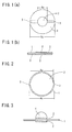
Fig. 1 ] Explanatory view of the construction of a quartz crystal oscillator (Fig. 1(a) is a plane view andFig.1(b) is a side view). - [
Fig.2 ] Explanatory view of a quartz crystal oscillator in a preferable embodiment in one mode for carrying out the invention. - [
Fig.3 ] Explanatory view of a liquefied material put in contact with the quartz crystal oscillator in one embodiment. - [
Fig.4 ] Explanatory view of a liquefied material put in contact with the quartz crystal oscillator in another embodiment. - [
Fig.5 ] View of the circuit composition of a biosensor apparatus for use in one Example of the invention. - [
Fig.6 ] Explanatory view of controllingrelays # 1 and #2 in the circuit. - [
Fig.7 ] View of a circuit composition depicting a variation example of the circuit composition inFig.5 . - [
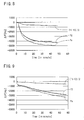
Fig.8 ] Graphs showing the measurement results in one Example of the invention. - [
Fig.9 ] Graphs showing the measurement results in Comparative Example. -
- 1. Quartz crystal plate
- 2. Electrode
- 3. Lead wire
- 4. Liquefied material
- 5. Container
- 6. Quartz crystal oscillator
- 7. π circuit
- 8. Network analyzer
- 9. RF generator
- 10. Personal computer
- 11. Frequency counter
- Any quartz crystal oscillators including quartz crystal oscillators for general use in QCM can be used with no specific limitation as the quartz crystal oscillator in accordance with the invention.
In accordance with the invention, agitation is done at other frequency different from a given frequency for use in measurement and equal to or higher than the fundamental vibration frequency of the quartz crystal oscillator. The other frequency is preferably the fundamental vibration frequency, the sub-vibration frequency or an Nth harmonic (overtone) (N = 3, 5, 7, ...) vibration frequency. Using for example a quartz crystal oscillator of 27 MHz as the fundamental vibration frequency, the other frequency is preferably selected to be; 27MHz or 135 MHz in case that the frequency for measurement is 81 MHz which is the 3rd harmonic frequency vibration frequency; and 81 MHz in case that 27MHz is used as the frequency for measurement. Among the frequencies described above to enhance the agitation efficiency, the fundamental vibration frequency or the sub-vibration frequency is preferably selected.
The frequency for use in measurement may be the fundamental vibration frequency, however, an Nth harmonic vibration frequency which is less influenced by compressional wave is preferably used.
During agitation, preferably, the quartz crystal oscillator is continuously vibrated at any one of the frequencies or the quartz crystal oscillator is vibrated at a frequency sweeping within a range of ± 100 kHz around the center of any one of the frequencies. - For measurement, the quartz crystal oscillator is applied with a load of an electric power of about 1 mW to oscillate and then the variation of the frequency is measured or the change of resonance frequency is measured by using a network analyzer or an impedance analyzer. Agitation is preferably carried out at an electric power ranging from 10-to 100-fold the electric power loaded on the quartz crystal oscillator during measurement. In case of the electric power, furthermore, the measured frequency may sometimes get unstable possibly involving a big noise, and therefore, it is preferable that agitation and measurement are done alternately or agitation is done before measurement.
- The frequency may also be measured, using a network analyzer or an impedance analyzer or by a measurement method with a frequency counter during direct oscillation of the quartz crystal oscillator. During the use of a network analyzer, the frequency can be measured with or without use of π circuit. Quartz crystal oscillators for use in measurement and agitation may be set at not only one channel but also multi channels.
- The invention will now be described specifically with reference to drawings.
The quartz crystal oscillator for use in accordance with the invention includes, for example, a quartz crystal oscillator of the construction shown inFig.1 . The quartz crystal oscillator is generally used for QCM, wherecounter electrodes quartz crystal plate 1. For the 27-MHz specification, thequartz crystal plate 1 is about 60 µm in thickness and about 8.9 mm in diameter (Rc). Thecounter electrode 3 is made of, for example, gold and of a diameter (Re) of about 2.5 mm. - As shown in
Fig.2 , more preferably, the diameter of theelectrode 2 is about 8 mm, larger than the electrode of the general quartz crystal oscillator in the construction described above. The reason is that heat generated during agitation can be dispersed to suppress temperature increase of the quartz crystal oscillator and the solution, allowing the measurement at a lower noise. Herein, the electrode may be formed on any one or both of the surface and back faces. - So as to put a liquefied material in contact with the electrodes by using the quartz crystal oscillator, a method for arranging a
solution 4 on thegold electrode 2 as shown inFig.3 , a method for arranging the quartz crystal oscillator on the bottom of acontainer 5 and injecting a trace volume (about 500 µl or less) of thesolution 4 above the quartz crystal oscillator as shown inFig.5 , or a flow cell may be used but without any limitation. - One Example of the invention is now described.
In the present Example, measurement was carried out by arranging a solution on one electrode of the gold electrodes arranged on both the faces of the quartz crystal oscillator of the fundamental vibration frequency of 27 MHz, as shown inFig.3 so as to set the volume of a liquid as a handling subject to a trace volume.
The quartz crystal oscillator was connected to a circuit shown inFig.5 .
The depicted circuit is composed of a circuit connecting thequartz crystal oscillator 6 throughcircuit 7 to anetwork analyzer 8 and a circuit connecting thequartz crystal oscillator 6 to anRF generator 9. These circuits can freely be switched on and off with tworelays # 1 and #2. Theserelays # 1 and #2 are controlled with apersonal computer 10; in case that therelay # 1 is closed, the quartz crystal oscillator oscillates for measurement; in case that therelay # 2 is closed, the quartz crystal oscillator enforces agitation. - In case of carrying out the measurement with the
quartz crystal oscillator 6, the quartz crystal oscillator was set to vibrate at a frequency around 81 MHz which is the 3rd harmonic frequency frequency; in case of enforcing agitation, the quartz crystal oscillator was set to vibrate at a frequency around the fundamental frequency (27 MHz) or around the sub-vibration frequency of the fundamental frequency of the fundamental wave (scanning within a range of ± 100 kHz). The input electric power was 2 mW for the measurement and 200 mW for the agitation.
As shown inFig.6 , therelay # 1 was controlled so as to repeat ON and OFF modes every one second, while therelay # 2 was controlled so as to repeat taking ON mode for 300 milliseconds simultaneously with the start of the OFF mode of therelay # 1 and then taking OFF mode thereafter. - Next, 9 µl of the buffer solution was placed on the gold electrode of the
quartz crystal oscillator Figs. 8 and 9 show the measurement results with agitation under controls of therelays # 1 and #2 and without agitation, respectively. -
Fig.8 shows that in the case with agitation, the variation of the frequency as measured after the N-avidin injection was on a gradually decreasing curve and the time required for the frequency to be stabilized was shorter compared with the case with no agitation. In the case with no agitation as shown inFig.9 , in contrast, the frequency measured was decreased by -1000 Hz immediately after the N-avidin injection and then at a more or less leveled-off state and subsequently, decreased. This indicates that the frequency measured requires a time for stabilization in the case with no agitation. - The results show that agitation of a solution of as trace as several micro-liters level can be done with no dedicated agitation unit, enabling the analysis of the binding amount and the binding rate at a high precision.
- The circuit composition example described above is just an exemplification. Even a circuit using a frequency counter 11 so as to oscillate the quartz crystal oscillator instead of the network analyzer as shown in
Fig.7 can also be used. - The invention can be utilized in a wide variety of fields for assaying interactions between biological substances such as DNA and proteins or assaying antigen-antibody reactions.
Claims (6)
- A method for agitating a liquefied material using a quartz crystal oscillator in vibrating the quartz crystal oscillator at a given frequency and measuring the variation of the frequency due to a substance in contact with the quartz crystal oscillator, characterized in that the quartz crystal oscillator is vibrated at other frequency different from the given frequency and equal to or higher than the fundamental vibration frequency to agitate a liquid containing the substance.
- A method for agitating a liquefied material using a quartz crystal oscillator according to claim 1, characterized in that the other frequency is the fundamental vibration frequency, the sub-vibration frequency or an Nth harmonic (N = 3, 5, 7, ...) vibration frequency.
- A method for agitating a liquefied material using a quartz crystal oscillator according to claim 1 or 2, characterized in that the quartz crystal oscillator is vibrated at the other frequency in a fixed way or vibrated at a frequency sweeping within a range of ± 100 kHz around the center of the other frequency, during the time of agitation.
- A method for agitating a liquefied material using a quartz crystal oscillator according to any of claims 1 through 3, characterized in that the electric power applied to the quartz crystal oscillator during the time of agitation is set to 10-fold or more the electric power during the time of measurement.
- A method for agitating a liquefied material using a quartz crystal oscillator according to any one of claims 1 through 4, characterized in that the quartz crystal oscillator is vibrated at an Nth harmonic (N = 3, 5, 7,...) vibration frequency during the time of measurement.
- A method for agitating a liquefied material using a quartz crystal oscillator according to any one of claims 1 through 5, characterized in that the agitation is done before the measurement or the agitation is done between individual measurements when the measurement is continuously carried out.
Applications Claiming Priority (2)
| Application Number | Priority Date | Filing Date | Title |
|---|---|---|---|
| JP2006312253A JP4755965B2 (en) | 2006-11-17 | 2006-11-17 | Method of stirring liquid using quartz crystal |
| PCT/JP2007/072318 WO2008059970A1 (en) | 2006-11-17 | 2007-11-16 | Method for agitating liquid material by using crystal oscillator |
Publications (3)
| Publication Number | Publication Date |
|---|---|
| EP2083256A1 true EP2083256A1 (en) | 2009-07-29 |
| EP2083256A4 EP2083256A4 (en) | 2017-02-15 |
| EP2083256B1 EP2083256B1 (en) | 2019-12-25 |
Family
ID=39401774
Family Applications (1)
| Application Number | Title | Priority Date | Filing Date |
|---|---|---|---|
| EP07832048.8A Active EP2083256B1 (en) | 2006-11-17 | 2007-11-16 | Method for agitating liquid material by using crystal oscillator |
Country Status (5)
| Country | Link |
|---|---|
| US (1) | US8413512B2 (en) |
| EP (1) | EP2083256B1 (en) |
| JP (1) | JP4755965B2 (en) |
| CN (1) | CN101548170B (en) |
| WO (1) | WO2008059970A1 (en) |
Families Citing this family (3)
| Publication number | Priority date | Publication date | Assignee | Title |
|---|---|---|---|---|
| JP4870530B2 (en) * | 2006-11-20 | 2012-02-08 | 日本無線株式会社 | Surface acoustic wave sensor |
| US8905624B1 (en) | 2009-08-20 | 2014-12-09 | Harold W. Howe | Control of vibratory/oscillatory mixers |
| WO2012053189A1 (en) * | 2010-10-20 | 2012-04-26 | 株式会社アルバック | Method of measuring viscoelasticity coefficients of material and device for measuring viscoelasticity coefficients of material |
Family Cites Families (27)
| Publication number | Priority date | Publication date | Assignee | Title |
|---|---|---|---|---|
| US5722A (en) * | 1848-08-22 | op plattsbtjrg | ||
| US3925734A (en) * | 1974-01-09 | 1975-12-09 | Scudder Smith | Oscillator device for generating signals of a precise frequency |
| DE3329261A1 (en) * | 1983-08-12 | 1985-02-28 | Kazanskij aviacionnyj institut imeni A. N. Tupoleva, Kazan' | Arrangement for testing products by random and harmonic vibrations |
| US4741200A (en) * | 1986-07-11 | 1988-05-03 | Ford Motor Company | Method and apparatus for measuring viscosity in a liquid utilizing a piezoelectric sensor |
| JPH01206254A (en) * | 1988-02-12 | 1989-08-18 | Nec Corp | Stirring mechanism for hemanalysis |
| US5201215A (en) * | 1991-10-17 | 1993-04-13 | The United States Of America As Represented By The United States Department Of Energy | Method for simultaneous measurement of mass loading and fluid property changes using a quartz crystal microbalance |
| AT398707B (en) * | 1993-05-11 | 1995-01-25 | Trampler Felix | MULTILAYER PIEZOELECTRIC RESONATOR FOR THE SEPARATION OF SUSPENDED PARTICLES |
| US5741961A (en) * | 1993-08-18 | 1998-04-21 | Sandia Corporation | Quartz resonator fluid density and viscosity monitor |
| JP3323343B2 (en) * | 1994-04-01 | 2002-09-09 | 日本碍子株式会社 | Sensor element and particle sensor |
| US5796506A (en) * | 1995-11-21 | 1998-08-18 | Tsai; Charles Su-Chang | Submillimeter indirect heterodyne receiver and mixer element |
| JPH1010034A (en) * | 1996-06-25 | 1998-01-16 | Ngk Insulators Ltd | Particle sensor |
| US6079252A (en) * | 1998-05-20 | 2000-06-27 | Advanced Technology Materials, Inc. | Leak detection device, and fluid vessel assembly comprising same |
| US6443900B2 (en) * | 2000-03-15 | 2002-09-03 | Olympus Optical Co., Ltd. | Ultrasonic wave transducer system and ultrasonic wave transducer |
| JP2002310872A (en) * | 2001-04-06 | 2002-10-23 | Ulvac Japan Ltd | Measuring method and measuring device |
| DE10117772C2 (en) * | 2001-04-09 | 2003-04-03 | Advalytix Ag | Mixing device and mixing method for mixing small amounts of liquid |
| JP3892743B2 (en) * | 2002-03-01 | 2007-03-14 | 日本碍子株式会社 | Reaction cell and method of use thereof |
| US20040092921A1 (en) * | 2002-10-21 | 2004-05-13 | Kadziauskas Kenneth E. | System and method for pulsed ultrasonic power delivery employing cavitation effects |
| JP4066795B2 (en) | 2002-12-04 | 2008-03-26 | 株式会社ジェイテクト | Inspection method for surface layer of metal parts |
| JP2004184256A (en) * | 2002-12-04 | 2004-07-02 | Citizen Watch Co Ltd | Qcm sensor apparatus and substance measuring method |
| JP2006523835A (en) * | 2003-04-17 | 2006-10-19 | アクビオ・リミテッド | Bursting event sensor device |
| US6990852B2 (en) * | 2003-07-28 | 2006-01-31 | Becton Dickinson & Company | System and method for detecting particles |
| JP4437022B2 (en) * | 2003-09-25 | 2010-03-24 | 株式会社アルバック | Measuring method and biosensor device using a vibrator used for tracking chemical reactions and analyzing conditions in the fields of biochemistry, medicine and food |
| US7331232B2 (en) * | 2003-09-25 | 2008-02-19 | Ulvac, Inc. | Measurement method and biosensor apparatus using resonator |
| JP2005351799A (en) * | 2004-06-11 | 2005-12-22 | Ulvac Japan Ltd | Surface elastic wave element, biosensor device, and measuring method by surface elastic wave element |
| US7878064B2 (en) * | 2004-06-12 | 2011-02-01 | Akubio Limited | Analytical apparatus with array of sensors and calibrating element |
| GB0506710D0 (en) * | 2005-04-01 | 2005-05-11 | Akubio Ltd | Cartridge for a fluid sample analyser |
| US20090287205A1 (en) * | 2008-05-16 | 2009-11-19 | Boston Scientific Scimed, Inc. | Systems and methods for preventing tissue popping caused by bubble expansion during tissue ablation |
-
2006
- 2006-11-17 JP JP2006312253A patent/JP4755965B2/en not_active Expired - Fee Related
-
2007
- 2007-11-16 US US12/515,312 patent/US8413512B2/en active Active
- 2007-11-16 EP EP07832048.8A patent/EP2083256B1/en active Active
- 2007-11-16 WO PCT/JP2007/072318 patent/WO2008059970A1/en not_active Ceased
- 2007-11-16 CN CN200780042452.4A patent/CN101548170B/en active Active
Non-Patent Citations (1)
| Title |
|---|
| See references of WO2008059970A1 * |
Also Published As
| Publication number | Publication date |
|---|---|
| WO2008059970A1 (en) | 2008-05-22 |
| EP2083256B1 (en) | 2019-12-25 |
| CN101548170B (en) | 2014-01-01 |
| US20100054076A1 (en) | 2010-03-04 |
| US8413512B2 (en) | 2013-04-09 |
| CN101548170A (en) | 2009-09-30 |
| EP2083256A4 (en) | 2017-02-15 |
| JP4755965B2 (en) | 2011-08-24 |
| JP2008128743A (en) | 2008-06-05 |
Similar Documents
| Publication | Publication Date | Title |
|---|---|---|
| CN103223313A (en) | Stirrer and sample analytical equipment | |
| JP5379909B2 (en) | Viscoelasticity measuring method and viscoelasticity measuring device | |
| US8413512B2 (en) | Method for agitating liquefied material using quartz crystal oscillator | |
| JP2017529540A (en) | Phase modulation standing wave mixing apparatus and method | |
| JP2009162585A (en) | Analyzer and analysis method | |
| JP2004325257A (en) | Analysis method using oscillator | |
| JP4669749B2 (en) | Measuring method and measuring apparatus using crystal resonator | |
| US7331232B2 (en) | Measurement method and biosensor apparatus using resonator | |
| JP2007010519A5 (en) | ||
| JP2002148295A (en) | Frequency measuring method, frequency measuring device and analyzer | |
| JP3841713B2 (en) | Substance inspection equipment | |
| JP2007198920A (en) | Stirring unit | |
| JP2002310872A (en) | Measuring method and measuring device | |
| JP4009221B2 (en) | Analysis method using vibrator | |
| WO2009001950A1 (en) | Sound wave generator, agitating device, and automatic analysis device | |
| JP3911191B2 (en) | Analysis method | |
| JP4437022B2 (en) | Measuring method and biosensor device using a vibrator used for tracking chemical reactions and analyzing conditions in the fields of biochemistry, medicine and food | |
| JP2005351799A (en) | Surface elastic wave element, biosensor device, and measuring method by surface elastic wave element | |
| JP2002277368A (en) | Measuring device and analyzer | |
| JP2006297257A (en) | Liquid agitating device and measuring device including it | |
| JP3954430B2 (en) | Concentration measurement method | |
| US20160129416A1 (en) | Microarray mini-mixer | |
| JPH0743288A (en) | Osmotic pressure measuring device | |
| JP2002156368A (en) | Characteristic measuring device and analyzing device | |
| JP2019144033A (en) | Reaction device, electric field agitator, and detection method |
Legal Events
| Date | Code | Title | Description |
|---|---|---|---|
| PUAI | Public reference made under article 153(3) epc to a published international application that has entered the european phase |
Free format text: ORIGINAL CODE: 0009012 |
|
| 17P | Request for examination filed |
Effective date: 20090515 |
|
| AK | Designated contracting states |
Kind code of ref document: A1 Designated state(s): AT BE BG CH CY CZ DE DK EE ES FI FR GB GR HU IE IS IT LI LT LU LV MC MT NL PL PT RO SE SI SK TR |
|
| DAX | Request for extension of the european patent (deleted) | ||
| RA4 | Supplementary search report drawn up and despatched (corrected) |
Effective date: 20170116 |
|
| RIC1 | Information provided on ipc code assigned before grant |
Ipc: G01N 29/02 20060101AFI20170110BHEP Ipc: B01F 11/02 20060101ALI20170110BHEP Ipc: G01N 29/036 20060101ALI20170110BHEP Ipc: B01F 13/00 20060101ALI20170110BHEP Ipc: G01N 29/22 20060101ALI20170110BHEP |
|
| REG | Reference to a national code |
Ref country code: DE Ref legal event code: R079 Ref document number: 602007059674 Country of ref document: DE Free format text: PREVIOUS MAIN CLASS: G01N0001280000 Ipc: G01N0029020000 |
|
| GRAP | Despatch of communication of intention to grant a patent |
Free format text: ORIGINAL CODE: EPIDOSNIGR1 |
|
| STAA | Information on the status of an ep patent application or granted ep patent |
Free format text: STATUS: GRANT OF PATENT IS INTENDED |
|
| RIC1 | Information provided on ipc code assigned before grant |
Ipc: G01N 29/036 20060101ALI20190625BHEP Ipc: B01F 13/00 20060101ALI20190625BHEP Ipc: G01N 29/22 20060101ALI20190625BHEP Ipc: G01N 29/02 20060101AFI20190625BHEP Ipc: B01F 11/02 20060101ALI20190625BHEP |
|
| INTG | Intention to grant announced |
Effective date: 20190716 |
|
| GRAS | Grant fee paid |
Free format text: ORIGINAL CODE: EPIDOSNIGR3 |
|
| GRAA | (expected) grant |
Free format text: ORIGINAL CODE: 0009210 |
|
| STAA | Information on the status of an ep patent application or granted ep patent |
Free format text: STATUS: THE PATENT HAS BEEN GRANTED |
|
| AK | Designated contracting states |
Kind code of ref document: B1 Designated state(s): AT BE BG CH CY CZ DE DK EE ES FI FR GB GR HU IE IS IT LI LT LU LV MC MT NL PL PT RO SE SI SK TR |
|
| REG | Reference to a national code |
Ref country code: GB Ref legal event code: FG4D |
|
| REG | Reference to a national code |
Ref country code: CH Ref legal event code: EP |
|
| REG | Reference to a national code |
Ref country code: AT Ref legal event code: REF Ref document number: 1217675 Country of ref document: AT Kind code of ref document: T Effective date: 20200115 |
|
| REG | Reference to a national code |
Ref country code: DE Ref legal event code: R096 Ref document number: 602007059674 Country of ref document: DE |
|
| REG | Reference to a national code |
Ref country code: IE Ref legal event code: FG4D |
|
| GRAT | Correction requested after decision to grant or after decision to maintain patent in amended form |
Free format text: ORIGINAL CODE: EPIDOSNCDEC |
|
| RAP2 | Party data changed (patent owner data changed or rights of a patent transferred) |
Owner name: ULVAC, INC. |
|
| REG | Reference to a national code |
Ref country code: NL Ref legal event code: MP Effective date: 20191225 |
|
| PG25 | Lapsed in a contracting state [announced via postgrant information from national office to epo] |
Ref country code: FI Free format text: LAPSE BECAUSE OF FAILURE TO SUBMIT A TRANSLATION OF THE DESCRIPTION OR TO PAY THE FEE WITHIN THE PRESCRIBED TIME-LIMIT Effective date: 20191225 Ref country code: BG Free format text: LAPSE BECAUSE OF FAILURE TO SUBMIT A TRANSLATION OF THE DESCRIPTION OR TO PAY THE FEE WITHIN THE PRESCRIBED TIME-LIMIT Effective date: 20200325 Ref country code: GR Free format text: LAPSE BECAUSE OF FAILURE TO SUBMIT A TRANSLATION OF THE DESCRIPTION OR TO PAY THE FEE WITHIN THE PRESCRIBED TIME-LIMIT Effective date: 20200326 Ref country code: LT Free format text: LAPSE BECAUSE OF FAILURE TO SUBMIT A TRANSLATION OF THE DESCRIPTION OR TO PAY THE FEE WITHIN THE PRESCRIBED TIME-LIMIT Effective date: 20191225 Ref country code: LV Free format text: LAPSE BECAUSE OF FAILURE TO SUBMIT A TRANSLATION OF THE DESCRIPTION OR TO PAY THE FEE WITHIN THE PRESCRIBED TIME-LIMIT Effective date: 20191225 Ref country code: SE Free format text: LAPSE BECAUSE OF FAILURE TO SUBMIT A TRANSLATION OF THE DESCRIPTION OR TO PAY THE FEE WITHIN THE PRESCRIBED TIME-LIMIT Effective date: 20191225 |
|
| REG | Reference to a national code |
Ref country code: LT Ref legal event code: MG4D |
|
| PG25 | Lapsed in a contracting state [announced via postgrant information from national office to epo] |
Ref country code: NL Free format text: LAPSE BECAUSE OF FAILURE TO SUBMIT A TRANSLATION OF THE DESCRIPTION OR TO PAY THE FEE WITHIN THE PRESCRIBED TIME-LIMIT Effective date: 20191225 Ref country code: EE Free format text: LAPSE BECAUSE OF FAILURE TO SUBMIT A TRANSLATION OF THE DESCRIPTION OR TO PAY THE FEE WITHIN THE PRESCRIBED TIME-LIMIT Effective date: 20191225 Ref country code: RO Free format text: LAPSE BECAUSE OF FAILURE TO SUBMIT A TRANSLATION OF THE DESCRIPTION OR TO PAY THE FEE WITHIN THE PRESCRIBED TIME-LIMIT Effective date: 20191225 Ref country code: PT Free format text: LAPSE BECAUSE OF FAILURE TO SUBMIT A TRANSLATION OF THE DESCRIPTION OR TO PAY THE FEE WITHIN THE PRESCRIBED TIME-LIMIT Effective date: 20200520 |
|
| PG25 | Lapsed in a contracting state [announced via postgrant information from national office to epo] |
Ref country code: IS Free format text: LAPSE BECAUSE OF FAILURE TO SUBMIT A TRANSLATION OF THE DESCRIPTION OR TO PAY THE FEE WITHIN THE PRESCRIBED TIME-LIMIT Effective date: 20200425 Ref country code: SK Free format text: LAPSE BECAUSE OF FAILURE TO SUBMIT A TRANSLATION OF THE DESCRIPTION OR TO PAY THE FEE WITHIN THE PRESCRIBED TIME-LIMIT Effective date: 20191225 |
|
| REG | Reference to a national code |
Ref country code: DE Ref legal event code: R097 Ref document number: 602007059674 Country of ref document: DE |
|
| PG25 | Lapsed in a contracting state [announced via postgrant information from national office to epo] |
Ref country code: ES Free format text: LAPSE BECAUSE OF FAILURE TO SUBMIT A TRANSLATION OF THE DESCRIPTION OR TO PAY THE FEE WITHIN THE PRESCRIBED TIME-LIMIT Effective date: 20191225 Ref country code: DK Free format text: LAPSE BECAUSE OF FAILURE TO SUBMIT A TRANSLATION OF THE DESCRIPTION OR TO PAY THE FEE WITHIN THE PRESCRIBED TIME-LIMIT Effective date: 20191225 Ref country code: CZ Free format text: LAPSE BECAUSE OF FAILURE TO SUBMIT A TRANSLATION OF THE DESCRIPTION OR TO PAY THE FEE WITHIN THE PRESCRIBED TIME-LIMIT Effective date: 20191225 |
|
| PLBE | No opposition filed within time limit |
Free format text: ORIGINAL CODE: 0009261 |
|
| STAA | Information on the status of an ep patent application or granted ep patent |
Free format text: STATUS: NO OPPOSITION FILED WITHIN TIME LIMIT |
|
| REG | Reference to a national code |
Ref country code: AT Ref legal event code: MK05 Ref document number: 1217675 Country of ref document: AT Kind code of ref document: T Effective date: 20191225 |
|
| PG25 | Lapsed in a contracting state [announced via postgrant information from national office to epo] |
Ref country code: SI Free format text: LAPSE BECAUSE OF FAILURE TO SUBMIT A TRANSLATION OF THE DESCRIPTION OR TO PAY THE FEE WITHIN THE PRESCRIBED TIME-LIMIT Effective date: 20191225 |
|
| 26N | No opposition filed |
Effective date: 20200928 |
|
| PG25 | Lapsed in a contracting state [announced via postgrant information from national office to epo] |
Ref country code: AT Free format text: LAPSE BECAUSE OF FAILURE TO SUBMIT A TRANSLATION OF THE DESCRIPTION OR TO PAY THE FEE WITHIN THE PRESCRIBED TIME-LIMIT Effective date: 20191225 |
|
| PG25 | Lapsed in a contracting state [announced via postgrant information from national office to epo] |
Ref country code: PL Free format text: LAPSE BECAUSE OF FAILURE TO SUBMIT A TRANSLATION OF THE DESCRIPTION OR TO PAY THE FEE WITHIN THE PRESCRIBED TIME-LIMIT Effective date: 20191225 |
|
| REG | Reference to a national code |
Ref country code: DE Ref legal event code: R119 Ref document number: 602007059674 Country of ref document: DE |
|
| PG25 | Lapsed in a contracting state [announced via postgrant information from national office to epo] |
Ref country code: MC Free format text: LAPSE BECAUSE OF FAILURE TO SUBMIT A TRANSLATION OF THE DESCRIPTION OR TO PAY THE FEE WITHIN THE PRESCRIBED TIME-LIMIT Effective date: 20191225 |
|
| REG | Reference to a national code |
Ref country code: CH Ref legal event code: PL |
|
| GBPC | Gb: european patent ceased through non-payment of renewal fee |
Effective date: 20201116 |
|
| PG25 | Lapsed in a contracting state [announced via postgrant information from national office to epo] |
Ref country code: LU Free format text: LAPSE BECAUSE OF NON-PAYMENT OF DUE FEES Effective date: 20201116 |
|
| REG | Reference to a national code |
Ref country code: BE Ref legal event code: MM Effective date: 20201130 |
|
| PG25 | Lapsed in a contracting state [announced via postgrant information from national office to epo] |
Ref country code: CH Free format text: LAPSE BECAUSE OF NON-PAYMENT OF DUE FEES Effective date: 20201130 Ref country code: LI Free format text: LAPSE BECAUSE OF NON-PAYMENT OF DUE FEES Effective date: 20201130 |
|
| PG25 | Lapsed in a contracting state [announced via postgrant information from national office to epo] |
Ref country code: FR Free format text: LAPSE BECAUSE OF NON-PAYMENT OF DUE FEES Effective date: 20201130 Ref country code: IE Free format text: LAPSE BECAUSE OF NON-PAYMENT OF DUE FEES Effective date: 20201116 |
|
| PG25 | Lapsed in a contracting state [announced via postgrant information from national office to epo] |
Ref country code: DE Free format text: LAPSE BECAUSE OF NON-PAYMENT OF DUE FEES Effective date: 20210601 Ref country code: GB Free format text: LAPSE BECAUSE OF NON-PAYMENT OF DUE FEES Effective date: 20201116 |
|
| PG25 | Lapsed in a contracting state [announced via postgrant information from national office to epo] |
Ref country code: TR Free format text: LAPSE BECAUSE OF FAILURE TO SUBMIT A TRANSLATION OF THE DESCRIPTION OR TO PAY THE FEE WITHIN THE PRESCRIBED TIME-LIMIT Effective date: 20191225 Ref country code: MT Free format text: LAPSE BECAUSE OF FAILURE TO SUBMIT A TRANSLATION OF THE DESCRIPTION OR TO PAY THE FEE WITHIN THE PRESCRIBED TIME-LIMIT Effective date: 20191225 Ref country code: CY Free format text: LAPSE BECAUSE OF FAILURE TO SUBMIT A TRANSLATION OF THE DESCRIPTION OR TO PAY THE FEE WITHIN THE PRESCRIBED TIME-LIMIT Effective date: 20191225 |
|
| PG25 | Lapsed in a contracting state [announced via postgrant information from national office to epo] |
Ref country code: BE Free format text: LAPSE BECAUSE OF NON-PAYMENT OF DUE FEES Effective date: 20201130 |
|
| PGFP | Annual fee paid to national office [announced via postgrant information from national office to epo] |
Ref country code: IT Payment date: 20251125 Year of fee payment: 19 |