EP2082934A1 - Motorcycle - Google Patents
Motorcycle Download PDFInfo
- Publication number
- EP2082934A1 EP2082934A1 EP09150851A EP09150851A EP2082934A1 EP 2082934 A1 EP2082934 A1 EP 2082934A1 EP 09150851 A EP09150851 A EP 09150851A EP 09150851 A EP09150851 A EP 09150851A EP 2082934 A1 EP2082934 A1 EP 2082934A1
- Authority
- EP
- European Patent Office
- Prior art keywords
- speed sensor
- wheel speed
- wheel
- swing arm
- disposed
- Prior art date
- Legal status (The legal status is an assumption and is not a legal conclusion. Google has not performed a legal analysis and makes no representation as to the accuracy of the status listed.)
- Granted
Links
Images




Classifications
-
- B—PERFORMING OPERATIONS; TRANSPORTING
- B60—VEHICLES IN GENERAL
- B60T—VEHICLE BRAKE CONTROL SYSTEMS OR PARTS THEREOF; BRAKE CONTROL SYSTEMS OR PARTS THEREOF, IN GENERAL; ARRANGEMENT OF BRAKING ELEMENTS ON VEHICLES IN GENERAL; PORTABLE DEVICES FOR PREVENTING UNWANTED MOVEMENT OF VEHICLES; VEHICLE MODIFICATIONS TO FACILITATE COOLING OF BRAKES
- B60T8/00—Arrangements for adjusting wheel-braking force to meet varying vehicular or ground-surface conditions, e.g. limiting or varying distribution of braking force
- B60T8/32—Arrangements for adjusting wheel-braking force to meet varying vehicular or ground-surface conditions, e.g. limiting or varying distribution of braking force responsive to a speed condition, e.g. acceleration or deceleration
- B60T8/321—Arrangements for adjusting wheel-braking force to meet varying vehicular or ground-surface conditions, e.g. limiting or varying distribution of braking force responsive to a speed condition, e.g. acceleration or deceleration deceleration
- B60T8/329—Systems characterised by their speed sensor arrangements
-
- B—PERFORMING OPERATIONS; TRANSPORTING
- B62—LAND VEHICLES FOR TRAVELLING OTHERWISE THAN ON RAILS
- B62K—CYCLES; CYCLE FRAMES; CYCLE STEERING DEVICES; RIDER-OPERATED TERMINAL CONTROLS SPECIALLY ADAPTED FOR CYCLES; CYCLE AXLE SUSPENSIONS; CYCLE SIDECARS, FORECARS, OR THE LIKE
- B62K19/00—Cycle frames
- B62K19/30—Frame parts shaped to receive other cycle parts or accessories
- B62K19/38—Frame parts shaped to receive other cycle parts or accessories for attaching brake members
Definitions
- the present invention relates to a motorcycle equipped with a wheel speed sensor for detecting the rotating speed of a wheel.
- a motorcycle including a disk brake caliper for applying a braking force to a wheel, a caliper bracket for fixing the disk brake caliper to the body frame side, and a wheel speed sensor attached to the caliper bracket so as to detect the rotating speed of the wheel has been known (refer to, for example, Patent Document 1 corresponding to Japanese Patent Laid-open N° 2007-78549 ( FIG. 3 ).
- a rear wheel 14 (the same reference symbols as in the document are used herein) is turnably mounted to an end part of a swing arm 12 through an axle 15, and a brake caliper 28 is mounted to the swing arm 12 through a brake caliper holder 27 extending toward the lower side.
- a rotation sensor 40 for detecting the rotating speed of the rear wheel 14 is mounted to the brake caliper holder 27, and a blocking wall 53 for receiving a foreign matter G such as a small stone flung up from a road surface during running is integrally provided in the periphery of the rotation sensor 40.
- the blocking wall 53 in Patent Document 1 can receive foreign matters G flying from the lower side, the front side or the rear side, thereby making it possible to obviate collision of foreign matter against the rotation sensor 40.
- the blocking wall 53 additionally provided for the rotation sensor 40 may lead to an increase in vehicle weight.
- the rotation sensor 40 since the rotation sensor 40 is disposed in the state of being exposed to a lateral side of the vehicle, collision of a foreign matter against the rotation sensor 40 cannot be obviated in the case where the foreign matter flies toward the rotation sensor 40 from the lateral side. In such a situation, a member for covering the rotation sensor 40 or the like member may be separately provided, whereby collision of foreign matter against the rotation sensor 40 can be obviated. This approach, however, may lead to an increase in the number of component parts or an increase in vehicle weight.
- the invention according to claim 1 resides in a motorcycle including a swing arm swingably provided on a body frame, a wheel rotatably provided at an end part of the swing arm, a disk plate attached to the wheel, a caliper bracket provided on the body frame side, a disk brake caliper for braking the wheel by clamping the disk plate, the disk brake caliper provided on the caliper bracket, and a wheel speed sensor for detecting the speed of the wheel, the wheel speed sensor attached to the caliper bracket, characterized in that the wheel speed sensor is disposed between the swing arm and the wheel, and the wheel speed sensor and the swing arm are so disposed as to overlap with each other in side view of the vehicle.
- the invention according to claim 2 is characterized in that the disk brake caliper is disposed on the lower side of the wheel speed sensor.
- the invention according to claim 3 is characterized in that an engaging part where the caliper bracket and the swing arm are engaged with each other is disposed on the upper side of the wheel speed sensor.
- the invention according to claim 4 is characterized in that the swing arm includes a drive shaft case for accommodating a drive shaft, and a final gear case for accommodating a final gear, and the wheel speed sensor and the final gear case are so disposed as to overlap with each other in side view of the vehicle.
- the wheel speed sensor is disposed between the swing arm and the wheel, and the wheel speed sensor and the swing arm are so disposed as to overlap with each other. This ensures that in the case where a foreign matter such as a small stone is flying toward the wheel speed sensor from a lateral side during running or in other situation, the foreign matter can be received by a side wall of the swing arm. Therefore, the possibility of collision of foreign matter against the wheel speed sensor or a cable or the like extending from the wheel speed sensor can be lowered, without separately providing means such as a guard member on the lateral side of the wheel speed sensor.
- the possibility of collision of foreign matter against the wheel speed sensor can be lowered, without leading to an increase in the number of component parts or an increase in vehicle weight.
- the disk brake caliper is disposed on the lower side of the wheel speed sensor. This ensures that in the case where a foreign matter such as a small stone is flying from the lower side toward the wheel speed sensor or the like during running or in other situation, the foreign matter can be received by the disk brake caliper. Since the foreign matter is received by the disk brake caliper, the possibility of direct collision of a foreign matter against the wheel speed sensor or the like can be lowered. Therefore, a foreign matter flying from a lateral side or the lower side can be prevented from colliding on the wheel speed sensor, without separately providing a protective member for exclusive use for protecting the wheel speed sensor.
- an engaging part of the caliper bracket is disposed on the upper side of the wheel speed sensor. This ensures that in the case where a foreign matter such as a small stone is flying from the upper side during running or in other situation, the foreign matter can be received by the engaging part. Therefore, the possibility of collision of foreign matter against the wheel speed sensor can be lowered, without separately providing a protective member for exclusive use for protecting the wheel speed sensor.
- the wheel speed sensor is covered by disposing the engaging part on the upper side of the wheel speed sensor in addition to the structures on the left and right sides, the front and rear sides and the lower side, external visibility of the wheel speed sensor can be lowered and, hence, appearance quality of the vehicle can be enhanced.
- the swing arm includes the drive shaft case for accommodating the drive shaft, and the final gear case for accommodating the final gear, and the wheel speed sensor and the final gear case are so disposed as to overlap with each other.
- FIG. 1 is an essential part side view of a motorcycle equipped with a wheel speed sensor
- FIG. 2 is a sectional view taken along line 2-2 of FIG. 1
- FIG. 3 is a sectional view taken along line 3-3. Now, description will be made by referring to FIGS. 1 to 3 .
- a swing arm 11 is provided at a rear part of a body frame constituting the motorcycle 10, and a rear wheel axle 14 for turnably supporting a rear wheel 13 as a wheel 12 is provided at an end part 11a of the swing arm 11.
- the rear wheel 13 is turnably attached to the rear wheel axle 14.
- the rear wheel 13 as the wheel 12 includes a hub part 16 constituting a central part and supported by the rear wheel axle 14, a rim part 17 which is disposed on the outside of the hub part 16 and to which a tire T is mounted, and an intermediate part 18 for connection between the hub part 16 and the rim part 17.
- a wheel speed plate 22 operative to detect the wheel speed by being paired with a wheel speed sensor (described later), formed in a circular disk-like shape, and provided with a multiplicity of radial slits 21 ⁇ ( ⁇ represents plurality, here and hereinbelow) in the vicinity of the outer periphery thereof is attached to the hub part 16 through small bolts 23 ⁇ .
- a circular disk-like disk plate 24 is attached to the hub part 16 on the outside of the wheel speed plate 22 through plate holding bolts 25 ⁇ .
- Bearings 26a to 26c are interposed between the rear wheel axle 14 and the hub part 16, whereby the hub part 16 is rotatably mounted to the rear wheel axle 14.
- Symbols 27a, 27b represent seal members.
- left and right rear cushions 28L, 28R are interposed between a rear part 11b of the swing arm 11 and the body frame, whereby the rear wheel 13 can be swingably supported.
- a sprocket 32 is attached to the hub part 16 through sprocket bolts 31 ⁇ , a chain 33 is wrapped around the sprocket 32, and a driving force by driving means is transmitted to the hub part 16 of the rear wheel 13, whereby the rear wheel 13 is driven.
- the rear wheel axle 14 includes the hub part 16, the disk plate 24 and the wheel speed plate 22 attached to the outside of the hub part 16 to be integral with the hub part 16, a disk brake caliper 35 which is mounted from the outside of the disk plate 24 so as to clamp disk parts 24a, 24b of the disk plate 24 and which clamps the disk plate 24 so as to brake the wheel 12, the swing arm 11 mounted to the outside of the disk brake caliper 35, and an axle nut 38 attached to the outside of the swing arm 11, in this order from the center of the vehicle body toward the right outer side.
- the caliper bracket 36 is a member for supporting the disk brake caliper 35 for braking the wheel 12.
- the disk brake caliper 35 is attached to a lower part of the caliper bracket 36 through fastening members 37, 37.
- the disk plate 24 is attached to the rear wheel 13 provided as the wheel 12, and the disk brake caliper 35 is provided on the body frame side.
- the disk brake caliper 35 is provided on the side of the body frame, through the caliper bracket 36 therebetween.
- the wheel speed sensor 41 for detecting the speed of the wheel 12 is attached to the caliper bracket 36 so as to front on slit holes 21 ⁇ provided in the wheel speed plate 22 serving as the rotation side.
- This type of wheel speed sensor 41 is used, for example, in an ABS (Antilock Braking System).
- ABS Antilock Braking System
- a hydraulic brake hose for connection to the disk brake caliper 35 is omitted.
- the wheel speed sensor 41 is a member which includes a detecting part 42 disposed to front on the wheel speed plate 22 so as to detect a signal through the slit holes 21 ⁇ , a flange part 43 holdably provided in the disk brake caliper 35 as a mounting part, and a cap part 44 from which a cable for outputting a signal obtained upon detection by the detecting part 42 is extended.
- the wheel speed sensor 41 is mounted to a sensor mounting seat part 54 of the disk brake caliper 35 through a sensor mounting bolt 45.
- the disk brake caliper 35 is provided with a first rib part 51 extending radially from the rear wheel axle 14 toward the front side of the vehicle, a second rib part 52 similarly extending from the rear wheel axle 14 toward the lower side of the vehicle, and a third rib part 53 being substantially parallel to the second rib part 52 and extending from an end part 51a of the first rib part 51 toward the lower side, so as to provide such a strength as to sufficiently endure a force tending to turn the caliper bracket 36 at the time of braking.
- the sensor mounting seat part 54 which serves as a seat surface for mounting the wheel speed sensor 41 thereon and which is formed to be thinner than the rib parts 51 to 53.
- an engaging part 55 for holding the caliper bracket 36 on the swing arm 11 is provided.
- the engaging part 55 is attached to the swing arm 11 along the direction from the inside to the outside of the vehicle through anti-turn bolt 56 so as to prevent the caliper bracket 36 from turning around the rear wheel axle 14 at the time of braking.
- symbol 57 denotes a hole part which is attached to the rear wheel shaft 14 so as to pass the rear wheel shaft 14 therethrough
- symbol 58 denotes a small hole so bored that the detecting part 42 of the wheel speed sensor 41 can be set to front on the slit holes 21 ⁇ provided in the wheel speed plate 22.
- the wheel speed sensor 41 is disposed between the swing arm 11 and the wheel 12, and the wheel speed sensor 41 and the swing arm 11 are so disposed as to overlap with each other in side view of the vehicle.
- the disk brake caliper 35 is disposed on the lower side of the wheel speed sensor 41.
- the engaging part 55 where the caliper bracket 36 and the swing arm 11 are engaged with each other is disposed on the front and the upper side of the wheel speed sensor 41.
- the second rib part 52 extending substantially downwards from the rear wheel axle 14 and the third rib part 53 disposed on the front side of and substantially in parallel to the second rib part 52 are formed in such directions as to be substantially parallel to each other for fulfilling the basic function of the caliper bracket 36 to hold the disk brake caliper 35 with a predetermined strength, and also have the role as a protective wall for preventing foreign matter coming from the front side or the rear side from colliding against the wheel speed sensor 41.
- the disk brake caliper 35 includes, as main components, a right body part 61R and a left body part 61L disposed opposite to the right body part 61R with a bridge bolt 62 therebetween, left and right pistons parts 63L and 63R which are attached respectively to the left and right body parts 61L and 61R and which are driven by a hydraulic pressure generated in a master cylinder (not shown), and left and right brake pads 64L and 64R which are attached respectively to the left and right piston parts 63L and 63R and which clamp the circular disk-like disk plate 24 therebetween at a predetermined time.
- Symbols 65a and 65b denote piston seals.
- the disk brake caliper 35 is disposed on the lower side of the wheel speed sensor 41, which is attached to the caliper bracket 36, and a cable part 67 extending from the wheel speed sensor 41.
- the wheel speed sensor is disposed at the rear wheel in this embodiment, it may be disposed at a front wheel while having the same configuration as above.
- FIGS. 4(a) and 4(b) are an operation illustration in section along line 4a-4a of FIG. 1 and an operation illustration in section along line 4b-4b of FIG. 1 .
- the periphery of the detecting part 42 constituting the wheel speed sensor 41 is covered with the caliper bracket 36, the first rib part 51 is disposed on the upper side of the cap part 44, and the disk brake caliper 35 is disposed on the lower side of the cap part 44.
- the foreign matter can be received by the first rib part 51, so that the foreign matter such as mud, small stones and gravel can be prevented from colliding against the wheel speed sensor 41.
- the disk brake caliper 35 is disposed on the lower side of the wheel speed sensor 41, so that in the case where a foreign matter such as a small stone flies in the direction of arrow (2) in the figure during running or in other situation, the foreign matter can be received by the disk brake caliper 35. Since the foreign matter is received by the disk brake caliper 35, the possibility of direct collision of the foreign matter on the wheel speed sensor 41 or the cap part 44 constituting the wheel speed sensor 41 can be lowered.
- the wheel speed sensor 41 is disposed between the swing arm 11 and the wheel 12, and the wheel speed sensor 41 and the swing arm 11 are so disposed as to overlap with each other.
- a foreign matter such as a small stone flies from the left or right side toward the wheel speed sensor 41, for example, in the direction of arrow (3) in the figure or in the direction of arrow (4) in the figure during running or in other situation, the foreign matter can be received by either of the wheel 12 and a side wall 11c of the swing arm 11.
- the possibility of collision of a foreign matter against the wheel speed sensor 41 or the cable part 67 or the like connected to the wheel speed sensor 41 can be lowered, without separately providing means such as a guard member in the vicinity of the wheel speed sensor 41 for the purpose of preventing foreign matters from colliding on the wheel speed sensor 41.
- a foreign matter flying from any of the lateral sides, the upper side and the lower side can be prevented from colliding against the wheel speed sensor 41, without separately providing a protective member for exclusive use for protecting the wheel speed sensor 41. Since it is unnecessary to separately provide a member for exclusive use, the possibility of collision of a foreign matter against the wheel speed sensor 41 can be lowered, without leading to an increase in the number of component parts or an increase in vehicle weight.
- the engaging part 55 is disposed for the wheel speed sensor 41 on the upper side of the wheel speed sensor 41. This ensures that in the case where a foreign matter such as a small stone flies from the upper side during running or in other situation, the foreign matter can be received by the engaging part 55, so that the possibility of collision of the foreign matter against the wheel speed sensor 41 can be lowered. In this case, the wheel speed sensor 41 can be protected from collision of a foreign matter thereon, without enlarging too much a rib-shaped part provided on the caliper bracket 36 in the vicinity of the wheel speed sensor 41 or separately providing a guard member for exclusive use. Therefore, a decrease in vehicle weight can be promised.
- the engaging part 55 is disposed on the upper side of the wheel speed sensor 41, in addition to the structures on the left and right sides, the front and rear sides and the lower side, and the wheel speed sensor 41 is covered with the engaging part 55.
- the wheel speed sensor 41 can be made more difficult to see from the outside, and appearance quality of the vehicle can be enhanced.
- FIG. 5 illustrates another embodiment of FIG. 1
- FIG. 6 is a sectional view taken along line 6-6 of FIG. 5 . Now, description will be made referring to FIGS. 5 and 6 .
- Another embodiment differs much from the above-described embodiment in that the driving of a wheel 12B (rear wheel 13B) has been changed from chain drive to shaft drive, the other points being not largely different. The following description will be centered on the differences.
- a rear wheel driving part 71 is provided with a drive shaft case 73 which serves also as a swing arm 11B and which accommodates a drive shaft 72 for driving the rear wheel 13B, and a final gear case 75 which is attached to a rear end part 73a of the drive shaft case 73 and which accommodates a pair of final gear sets 74 for conversion of the direction of the driving force.
- the wheel 12B is turnably mounted to the final gear case 75.
- a caliper bracket 36B is attached to an inside surface of the final gear case 75 through fastening bolts 76, 76 set to extend from the inside to the outside, and a wheel speed sensor 41B is attached to the caliper bracket 36B.
- the wheel speed sensor 41B is disposed between the drive shaft case 73 serving also as the swing arm 11B and the wheel 12B, and the wheel speed sensor 41B and the swing arm 11B are so disposed as to overlap with each other in side view of the vehicle.
- a transverse rib 81 is additionally provided on the upper side of the cap part 44B constituting the wheel speed sensor 41B, and a longitudinal rib 82 is additionally provided on the front side of the cap part 44B.
- the disk brake caliper 35B is disposed on the lower side of the wheel speed sensor 41B.
- An engaging part 55B where the caliper bracket 36B is engaged with the swing arm 11B is disposed substantially on the lower side of the wheel speed sensor 41.
- a universal joint 83 for enabling slide in the front-rear direction is interposed at an intermediate part of a drive shaft 72, and a final gear set 74 for converting the direction of a driving force is provided between a rear end part 72a of the drive shaft 72 and a rear wheel axle 14B.
- the final gear set 74 includes a pinion gear 84 as a first final gear, and a ring gear 85 as a second final gear.
- a pinion gear shaft 92 having the pinion gear 84 at a rear end part thereof is attached to a rear end part 72a of the drive shaft 72, the ring gear 85 is meshed with the pinion gear 84, and the ring gear 85 is turnably disposed coaxially with the center of the rear wheel axle 14B.
- Symbol 89 denotes a wheel bolt for attaching the wheel 12B to an output rotating body 91.
- the ring gear 85 is attached to the output rotating body 91.
- the pinion gear 84 and the pinion gear shaft 92 are formed as one body with each other.
- symbol 93 denotes a spline part which is formed in the pinion gear shaft 92 and serves as a connecting part for connection with the drive shaft 72
- symbol 94 denotes a C-clip.
- a driving force transmitted to the drive shaft 72 is transmitted to the pinion gear 84 through the pinion gear shaft 92, is then transmitted to the ring gear 85 meshed with the pinion gear 84, is transmitted to the output rotating body 91 fixed to the ring gear 85, and is transmitted to a hub part 16B of the rear wheel 13B.
- the universal joint 83 interposed in the drive shaft 72 is a tripod-type constant velocity joint having a slide structure capable of sliding in the axial direction of the drive shaft 72.
- the universal joint 83 may be a universal joint having a slide structure, and may be used as a universal joint whether it is of a non-constant velocity type or of a constant velocity type.
- a driving chamber 86 for accommodating the final gear set 74 is formed on the inside of the final gear case 75.
- the driving chamber 86 is filled with oil.
- Symbols 87a to 87d denote bearings, and symbol 88 denotes a seal member. The above structure ensures that the driving force of the drive shaft 72 is smoothly transmitted to the rear wheel 13B.
- FIGS. 7(a) and 7(b) are an operation illustration in section along line 7a-7a of FIG. 5 and an operation illustration in section along line 7b-7b of FIG. 5 .
- FIG. 7(a) the periphery of a detecting part 42B constituting a wheel speed sensor 41B is covered with a caliper bracket 36B, a transverse rib 81 is disposed on the upper side of a cap part 44B, and a disk brake caliper 35B is disposed on the lower side of the cap part 44B.
- the wheel speed sensor 41B is disposed between the swing arm 11B and the wheel 12B, and the wheel speed sensor 41B and the swing arm 11B are so disposed as to overlap with each other.
- a foreign matter such as a small stone comes flying toward the wheel speed sensor 41B from the left or right side, such as in the direction of arrow (3) of the figure or in the direction of arrow (4) of the figure, the foreign matter can be received by one of the wheel 12B, the disk plate 24B and a side wall 75b of the final gear case 75 constituting a part of the swing arm 11B.
- the foreign matter can be received by a longitudinal rib 82.
- the foreign matter can be received by the final gear case 75.
- a cable part 67B connected to the wheel speed sensor 41B or the like can be lowered, without separately providing means such as a guard member in the vicinity of the wheel speed sensor 41B for the purpose of preventing collision of foreign matter against the wheel speed sensor 41B.
- the possibility of collision of foreign matter against the wheel speed sensor 41B can be lowered, without leading to an increase in the number of component parts or an increase in vehicle weight.
- the present invention has been applied to a motorcycle in the mode of carrying out the invention, the invention is applicable also to saddle ride type vehicles, and may naturally be applied to general vehicles.
- the disk brake caliper may not necessarily be disposed on the lower side of the wheel speed sensor.
- the disk brake caliper may be disposed on the upper side of the wheel speed sensor, and may be disposed on the rear side of the wheel speed sensor.
- the engaging part may not necessarily be disposed on the upper side of the wheel speed sensor.
- the engaging part may be disposed on the lower side of the wheel speed sensor.
- the present invention is suitable for application to a motorcycle equipped with a wheel speed sensor.
Landscapes
- Engineering & Computer Science (AREA)
- Mechanical Engineering (AREA)
- Transportation (AREA)
- Regulating Braking Force (AREA)
- Braking Arrangements (AREA)
- Axle Suspensions And Sidecars For Cycles (AREA)
Abstract
Description
- The present invention relates to a motorcycle equipped with a wheel speed sensor for detecting the rotating speed of a wheel.
- A motorcycle including a disk brake caliper for applying a braking force to a wheel, a caliper bracket for fixing the disk brake caliper to the body frame side, and a wheel speed sensor attached to the caliper bracket so as to detect the rotating speed of the wheel has been known (refer to, for example,
Patent Document 1 corresponding to Japanese Patent Laid-open N°2007-78549 FIG. 3 ). - In
FIG. 3 ofPatent Document 1, a rear wheel 14 (the same reference symbols as in the document are used herein) is turnably mounted to an end part of a swing arm 12 through an axle 15, and a brake caliper 28 is mounted to the swing arm 12 through a brake caliper holder 27 extending toward the lower side. - A rotation sensor 40 for detecting the rotating speed of the
rear wheel 14 is mounted to the brake caliper holder 27, and a blockingwall 53 for receiving a foreign matter G such as a small stone flung up from a road surface during running is integrally provided in the periphery of the rotation sensor 40. - The blocking
wall 53 inPatent Document 1 can receive foreign matters G flying from the lower side, the front side or the rear side, thereby making it possible to obviate collision of foreign matter against the rotation sensor 40. - However, the
blocking wall 53 additionally provided for the rotation sensor 40 may lead to an increase in vehicle weight. In addition, since the rotation sensor 40 is disposed in the state of being exposed to a lateral side of the vehicle, collision of a foreign matter against the rotation sensor 40 cannot be obviated in the case where the foreign matter flies toward the rotation sensor 40 from the lateral side. In such a situation, a member for covering the rotation sensor 40 or the like member may be separately provided, whereby collision of foreign matter against the rotation sensor 40 can be obviated. This approach, however, may lead to an increase in the number of component parts or an increase in vehicle weight. - It is an object of the present invention to provide, in relation to a motorcycle having a wheel speed sensor, a technology for lowering the possibility of collision of a foreign matter against the wheel speed sensor, without leading to an increase in the number of component parts or an increase in vehicle weight.
- In order to do this, the invention according to
claim 1 resides in a motorcycle including a swing arm swingably provided on a body frame, a wheel rotatably provided at an end part of the swing arm, a disk plate attached to the wheel, a caliper bracket provided on the body frame side, a disk brake caliper for braking the wheel by clamping the disk plate, the disk brake caliper provided on the caliper bracket, and a wheel speed sensor for detecting the speed of the wheel, the wheel speed sensor attached to the caliper bracket, characterized in that the wheel speed sensor is disposed between the swing arm and the wheel, and the wheel speed sensor and the swing arm are so disposed as to overlap with each other in side view of the vehicle. - The invention according to
claim 2 is characterized in that the disk brake caliper is disposed on the lower side of the wheel speed sensor. - The invention according to
claim 3 is characterized in that an engaging part where the caliper bracket and the swing arm are engaged with each other is disposed on the upper side of the wheel speed sensor. - The invention according to
claim 4 is characterized in that the swing arm includes a drive shaft case for accommodating a drive shaft, and a final gear case for accommodating a final gear, and the wheel speed sensor and the final gear case are so disposed as to overlap with each other in side view of the vehicle. - In the invention according to
claim 1, the wheel speed sensor is disposed between the swing arm and the wheel, and the wheel speed sensor and the swing arm are so disposed as to overlap with each other. This ensures that in the case where a foreign matter such as a small stone is flying toward the wheel speed sensor from a lateral side during running or in other situation, the foreign matter can be received by a side wall of the swing arm. Therefore, the possibility of collision of foreign matter against the wheel speed sensor or a cable or the like extending from the wheel speed sensor can be lowered, without separately providing means such as a guard member on the lateral side of the wheel speed sensor. - Thus, according to the present invention, the possibility of collision of foreign matter against the wheel speed sensor can be lowered, without leading to an increase in the number of component parts or an increase in vehicle weight.
- In the invention according to
claim 2, the disk brake caliper is disposed on the lower side of the wheel speed sensor. This ensures that in the case where a foreign matter such as a small stone is flying from the lower side toward the wheel speed sensor or the like during running or in other situation, the foreign matter can be received by the disk brake caliper. Since the foreign matter is received by the disk brake caliper, the possibility of direct collision of a foreign matter against the wheel speed sensor or the like can be lowered. Therefore, a foreign matter flying from a lateral side or the lower side can be prevented from colliding on the wheel speed sensor, without separately providing a protective member for exclusive use for protecting the wheel speed sensor. - In the invention according to
claim 3, an engaging part of the caliper bracket is disposed on the upper side of the wheel speed sensor. This ensures that in the case where a foreign matter such as a small stone is flying from the upper side during running or in other situation, the foreign matter can be received by the engaging part. Therefore, the possibility of collision of foreign matter against the wheel speed sensor can be lowered, without separately providing a protective member for exclusive use for protecting the wheel speed sensor. - Besides, since the wheel speed sensor is covered by disposing the engaging part on the upper side of the wheel speed sensor in addition to the structures on the left and right sides, the front and rear sides and the lower side, external visibility of the wheel speed sensor can be lowered and, hence, appearance quality of the vehicle can be enhanced.
- In the invention according to
claim 4, the swing arm includes the drive shaft case for accommodating the drive shaft, and the final gear case for accommodating the final gear, and the wheel speed sensor and the final gear case are so disposed as to overlap with each other. This ensures that in the case where a foreign matter such as a small stone is flying from a lateral side toward the wheel speed sensor during running or in other situation, the foreign matter can be received by a side wall of the final gear case. Therefore, the possibility of collision of foreign matter against the wheel speed sensor or a cable or the like extending from the wheel speed sensor can be lowered, without separately providing means such as a guard member on the lateral side of the wheel speed sensor. -
-
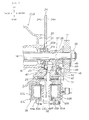
FIG. 1 is an essential part side view of a motorcycle equipped with a wheel speed sensor. -
FIG. 2 is a sectional view taken along line 2-2 ofFIG. 1 . -
FIG. 3 is a sectional view taken along line 3-3 ofFIG. 1 . -
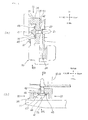
FIGS. 4(a) and 4(b) are an operation illustration in section along line 4a-4a ofFIG. 1 and an operation illustration in section alongline 4b-4b ofFIG. 1 . -
FIG. 5 is a view of another embodiment, corresponding toFIG. 1 . -
FIG. 6 is a sectional view taken alone line 6-6 ofFIG. 5 . -
FIGS. 7(a) and 7(b) are an operation illustration in section along line 7a-7a ofFIG. 5 and an operation illustration in section along line 7b-7b ofFIG. 5 . - A best mode for carrying out the present invention will be described below, based on the attached drawings. In this embodiment, a system obtained by applying the present invention to a rear wheel of a motorcycle will be described. In the drawings and the embodiment, the terms "UP," "DOWN," "FRONT," "REAR," "LEFT" and "RIGHT" mean the sides or directions as viewed from the driver seated on the motorcycle. Incidentally, the drawings should be viewed according to the posture of symbols.
-
FIG. 1 is an essential part side view of a motorcycle equipped with a wheel speed sensor,FIG. 2 is a sectional view taken along line 2-2 ofFIG. 1 , andFIG. 3 is a sectional view taken along line 3-3. Now, description will be made by referring toFIGS. 1 to 3 . - A
swing arm 11 is provided at a rear part of a body frame constituting the motorcycle 10, and arear wheel axle 14 for turnably supporting a rear wheel 13 as a wheel 12 is provided at anend part 11a of theswing arm 11. Thus, the rear wheel 13 is turnably attached to therear wheel axle 14. - The rear wheel 13 as the wheel 12 includes a
hub part 16 constituting a central part and supported by therear wheel axle 14, arim part 17 which is disposed on the outside of thehub part 16 and to which a tire T is mounted, and anintermediate part 18 for connection between thehub part 16 and therim part 17. - A
wheel speed plate 22 operative to detect the wheel speed by being paired with a wheel speed sensor (described later), formed in a circular disk-like shape, and provided with a multiplicity ofradial slits 21 ··· (··· represents plurality, here and hereinbelow) in the vicinity of the outer periphery thereof is attached to thehub part 16 throughsmall bolts 23 ···. A circular disk-like disk plate 24 is attached to thehub part 16 on the outside of thewheel speed plate 22 throughplate holding bolts 25 ···. -
Bearings 26a to 26c are interposed between therear wheel axle 14 and thehub part 16, whereby thehub part 16 is rotatably mounted to therear wheel axle 14.Symbols rear cushions 28L, 28R are interposed between arear part 11b of theswing arm 11 and the body frame, whereby the rear wheel 13 can be swingably supported. - A
sprocket 32 is attached to thehub part 16 throughsprocket bolts 31 ···, achain 33 is wrapped around thesprocket 32, and a driving force by driving means is transmitted to thehub part 16 of the rear wheel 13, whereby the rear wheel 13 is driven. - The
rear wheel axle 14 includes thehub part 16, thedisk plate 24 and thewheel speed plate 22 attached to the outside of thehub part 16 to be integral with thehub part 16, adisk brake caliper 35 which is mounted from the outside of thedisk plate 24 so as toclamp disk parts disk plate 24 and which clamps thedisk plate 24 so as to brake the wheel 12, theswing arm 11 mounted to the outside of thedisk brake caliper 35, and anaxle nut 38 attached to the outside of theswing arm 11, in this order from the center of the vehicle body toward the right outer side. - The
caliper bracket 36 is a member for supporting thedisk brake caliper 35 for braking the wheel 12. In this embodiment, thedisk brake caliper 35 is attached to a lower part of thecaliper bracket 36 through fasteningmembers - The
disk plate 24 is attached to the rear wheel 13 provided as the wheel 12, and thedisk brake caliper 35 is provided on the body frame side. Thedisk brake caliper 35 is provided on the side of the body frame, through thecaliper bracket 36 therebetween. Thewheel speed sensor 41 for detecting the speed of the wheel 12 is attached to thecaliper bracket 36 so as to front on slit holes 21 ··· provided in thewheel speed plate 22 serving as the rotation side. - This type of
wheel speed sensor 41 is used, for example, in an ABS (Antilock Braking System). In the drawings, a hydraulic brake hose for connection to thedisk brake caliper 35 is omitted. - The
wheel speed sensor 41 is a member which includes a detectingpart 42 disposed to front on thewheel speed plate 22 so as to detect a signal through the slit holes 21 ···, aflange part 43 holdably provided in thedisk brake caliper 35 as a mounting part, and acap part 44 from which a cable for outputting a signal obtained upon detection by the detectingpart 42 is extended. Thewheel speed sensor 41 is mounted to a sensor mountingseat part 54 of thedisk brake caliper 35 through asensor mounting bolt 45. - The
disk brake caliper 35 is provided with afirst rib part 51 extending radially from therear wheel axle 14 toward the front side of the vehicle, asecond rib part 52 similarly extending from therear wheel axle 14 toward the lower side of the vehicle, and athird rib part 53 being substantially parallel to thesecond rib part 52 and extending from an end part 51a of thefirst rib part 51 toward the lower side, so as to provide such a strength as to sufficiently endure a force tending to turn thecaliper bracket 36 at the time of braking. - In a region surrounded by the first to
third rib parts 51 to 53, the sensor mountingseat part 54 is provided which serves as a seat surface for mounting thewheel speed sensor 41 thereon and which is formed to be thinner than therib parts 51 to 53. - At the end part 51a of the
first rib part 51, an engagingpart 55 for holding thecaliper bracket 36 on theswing arm 11 is provided. The engagingpart 55 is attached to theswing arm 11 along the direction from the inside to the outside of the vehicle throughanti-turn bolt 56 so as to prevent thecaliper bracket 36 from turning around therear wheel axle 14 at the time of braking. - In the
caliper bracket 36,symbol 57 denotes a hole part which is attached to therear wheel shaft 14 so as to pass therear wheel shaft 14 therethrough, andsymbol 58 denotes a small hole so bored that the detectingpart 42 of thewheel speed sensor 41 can be set to front on the slit holes 21 ··· provided in thewheel speed plate 22. - Now, layout of the
wheel speed sensor 41 will be described. - The
wheel speed sensor 41 is disposed between theswing arm 11 and the wheel 12, and thewheel speed sensor 41 and theswing arm 11 are so disposed as to overlap with each other in side view of the vehicle. - In addition, the
disk brake caliper 35 is disposed on the lower side of thewheel speed sensor 41. - The engaging
part 55 where thecaliper bracket 36 and theswing arm 11 are engaged with each other is disposed on the front and the upper side of thewheel speed sensor 41. - The
second rib part 52 extending substantially downwards from therear wheel axle 14 and thethird rib part 53 disposed on the front side of and substantially in parallel to thesecond rib part 52 are formed in such directions as to be substantially parallel to each other for fulfilling the basic function of thecaliper bracket 36 to hold thedisk brake caliper 35 with a predetermined strength, and also have the role as a protective wall for preventing foreign matter coming from the front side or the rear side from colliding against thewheel speed sensor 41. - The
disk brake caliper 35 includes, as main components, aright body part 61R and aleft body part 61L disposed opposite to theright body part 61R with abridge bolt 62 therebetween, left andright pistons parts right body parts right brake pads right piston parts like disk plate 24 therebetween at a predetermined time.Symbols - The
disk brake caliper 35 is disposed on the lower side of thewheel speed sensor 41, which is attached to thecaliper bracket 36, and acable part 67 extending from thewheel speed sensor 41. Incidentally, while the wheel speed sensor is disposed at the rear wheel in this embodiment, it may be disposed at a front wheel while having the same configuration as above. - The operation of the motorcycle equipped with the wheel speed sensor according to the present invention as above-mentioned will be described below.
-
FIGS. 4(a) and 4(b) are an operation illustration in section along line 4a-4a ofFIG. 1 and an operation illustration in section alongline 4b-4b ofFIG. 1 . - In
FIG. 4(a) , the periphery of the detectingpart 42 constituting thewheel speed sensor 41 is covered with thecaliper bracket 36, thefirst rib part 51 is disposed on the upper side of thecap part 44, and thedisk brake caliper 35 is disposed on the lower side of thecap part 44. - In the case where a foreign matter flies in the direction of arrow (1) in the figure during running or in other situation, the foreign matter can be received by the
first rib part 51, so that the foreign matter such as mud, small stones and gravel can be prevented from colliding against thewheel speed sensor 41. - In addition, the
disk brake caliper 35 is disposed on the lower side of thewheel speed sensor 41, so that in the case where a foreign matter such as a small stone flies in the direction of arrow (2) in the figure during running or in other situation, the foreign matter can be received by thedisk brake caliper 35. Since the foreign matter is received by thedisk brake caliper 35, the possibility of direct collision of the foreign matter on thewheel speed sensor 41 or thecap part 44 constituting thewheel speed sensor 41 can be lowered. - In
FIG. 4(b) , thewheel speed sensor 41 is disposed between theswing arm 11 and the wheel 12, and thewheel speed sensor 41 and theswing arm 11 are so disposed as to overlap with each other. In the case where a foreign matter such as a small stone flies from the left or right side toward thewheel speed sensor 41, for example, in the direction of arrow (3) in the figure or in the direction of arrow (4) in the figure during running or in other situation, the foreign matter can be received by either of the wheel 12 and aside wall 11c of theswing arm 11. - Therefore, the possibility of collision of a foreign matter against the
wheel speed sensor 41 or thecable part 67 or the like connected to thewheel speed sensor 41 can be lowered, without separately providing means such as a guard member in the vicinity of thewheel speed sensor 41 for the purpose of preventing foreign matters from colliding on thewheel speed sensor 41. - According to the present invention, a foreign matter flying from any of the lateral sides, the upper side and the lower side can be prevented from colliding against the
wheel speed sensor 41, without separately providing a protective member for exclusive use for protecting thewheel speed sensor 41. Since it is unnecessary to separately provide a member for exclusive use, the possibility of collision of a foreign matter against thewheel speed sensor 41 can be lowered, without leading to an increase in the number of component parts or an increase in vehicle weight. - In addition, the engaging
part 55 is disposed for thewheel speed sensor 41 on the upper side of thewheel speed sensor 41. This ensures that in the case where a foreign matter such as a small stone flies from the upper side during running or in other situation, the foreign matter can be received by the engagingpart 55, so that the possibility of collision of the foreign matter against thewheel speed sensor 41 can be lowered. In this case, thewheel speed sensor 41 can be protected from collision of a foreign matter thereon, without enlarging too much a rib-shaped part provided on thecaliper bracket 36 in the vicinity of thewheel speed sensor 41 or separately providing a guard member for exclusive use. Therefore, a decrease in vehicle weight can be promised. - Further, the engaging
part 55 is disposed on the upper side of thewheel speed sensor 41, in addition to the structures on the left and right sides, the front and rear sides and the lower side, and thewheel speed sensor 41 is covered with the engagingpart 55. - Therefore, the
wheel speed sensor 41 can be made more difficult to see from the outside, and appearance quality of the vehicle can be enhanced. -
FIG. 5 illustrates another embodiment ofFIG. 1 , andFIG. 6 is a sectional view taken along line 6-6 ofFIG. 5 . Now, description will be made referring toFIGS. 5 and6 . - Another embodiment differs much from the above-described embodiment in that the driving of a
wheel 12B (rear wheel 13B) has been changed from chain drive to shaft drive, the other points being not largely different. The following description will be centered on the differences. - A rear wheel driving part 71 is provided with a
drive shaft case 73 which serves also as a swing arm 11B and which accommodates adrive shaft 72 for driving therear wheel 13B, and afinal gear case 75 which is attached to arear end part 73a of thedrive shaft case 73 and which accommodates a pair of final gear sets 74 for conversion of the direction of the driving force. Thewheel 12B is turnably mounted to thefinal gear case 75. - A
caliper bracket 36B is attached to an inside surface of thefinal gear case 75 throughfastening bolts wheel speed sensor 41B is attached to thecaliper bracket 36B. Thewheel speed sensor 41B is disposed between thedrive shaft case 73 serving also as the swing arm 11B and thewheel 12B, and thewheel speed sensor 41B and the swing arm 11B are so disposed as to overlap with each other in side view of the vehicle. - In addition, in the
caliper bracket 36B, atransverse rib 81 is additionally provided on the upper side of thecap part 44B constituting thewheel speed sensor 41B, and alongitudinal rib 82 is additionally provided on the front side of thecap part 44B. - The
disk brake caliper 35B is disposed on the lower side of thewheel speed sensor 41B. - An
engaging part 55B where thecaliper bracket 36B is engaged with the swing arm 11B is disposed substantially on the lower side of thewheel speed sensor 41. - Here, a rear wheel driving mechanism will be described. A
universal joint 83 for enabling slide in the front-rear direction is interposed at an intermediate part of adrive shaft 72, and a final gear set 74 for converting the direction of a driving force is provided between arear end part 72a of thedrive shaft 72 and arear wheel axle 14B. - The final gear set 74 includes a
pinion gear 84 as a first final gear, and aring gear 85 as a second final gear. Apinion gear shaft 92 having thepinion gear 84 at a rear end part thereof is attached to arear end part 72a of thedrive shaft 72, thering gear 85 is meshed with thepinion gear 84, and thering gear 85 is turnably disposed coaxially with the center of therear wheel axle 14B.Symbol 89 denotes a wheel bolt for attaching thewheel 12B to anoutput rotating body 91. Thering gear 85 is attached to theoutput rotating body 91. Thepinion gear 84 and thepinion gear shaft 92 are formed as one body with each other. In the figure,symbol 93 denotes a spline part which is formed in thepinion gear shaft 92 and serves as a connecting part for connection with thedrive shaft 72, andsymbol 94 denotes a C-clip. - A driving force transmitted to the
drive shaft 72 is transmitted to thepinion gear 84 through thepinion gear shaft 92, is then transmitted to thering gear 85 meshed with thepinion gear 84, is transmitted to theoutput rotating body 91 fixed to thering gear 85, and is transmitted to ahub part 16B of therear wheel 13B. - Incidentally, the universal joint 83 interposed in the
drive shaft 72 is a tripod-type constant velocity joint having a slide structure capable of sliding in the axial direction of thedrive shaft 72. Other than this, the universal joint 83 may be a universal joint having a slide structure, and may be used as a universal joint whether it is of a non-constant velocity type or of a constant velocity type. - A driving
chamber 86 for accommodating the final gear set 74 is formed on the inside of thefinal gear case 75. The drivingchamber 86 is filled with oil.Symbols 87a to 87d denote bearings, andsymbol 88 denotes a seal member. The above structure ensures that the driving force of thedrive shaft 72 is smoothly transmitted to therear wheel 13B. -
FIGS. 7(a) and 7(b) are an operation illustration in section along line 7a-7a ofFIG. 5 and an operation illustration in section along line 7b-7b ofFIG. 5 . - In
FIG. 7(a) , the periphery of a detectingpart 42B constituting awheel speed sensor 41B is covered with acaliper bracket 36B, atransverse rib 81 is disposed on the upper side of acap part 44B, and adisk brake caliper 35B is disposed on the lower side of thecap part 44B. - Therefore, in the case where a foreign matter flies in the direction of arrow (1) of the figure during running or in other situation, the foreign matter is received by the
transverse rib 81. - Accordingly, it is possible to prevent collision of a foreign matter such as mud, small stones and gravel against the
wheel speed sensor 41. Besides, in the case where a foreign matter flies in the direction of arrow (2) of the figure, the foreign matter is received by thedisk brake caliper 35B. Therefore, the foreign matter can be prevented from colliding on thewheel speed sensor 41B. Specifically, since the foreign matter is received by thedisk brake caliper 35B, the possibility of direct collision of a foreign matter on thecap part 44B of thewheel speed sensor 41B or the like can be lowered. - In
FIG. 7(b) , thewheel speed sensor 41B is disposed between the swing arm 11B and thewheel 12B, and thewheel speed sensor 41B and the swing arm 11B are so disposed as to overlap with each other. In the case where a foreign matter such as a small stone comes flying toward thewheel speed sensor 41B from the left or right side, such as in the direction of arrow (3) of the figure or in the direction of arrow (4) of the figure, the foreign matter can be received by one of thewheel 12B, thedisk plate 24B and aside wall 75b of thefinal gear case 75 constituting a part of the swing arm 11B. - In the case where a foreign matter comes flying in the direction of arrow (5) of the figure, the foreign matter can be received by a
longitudinal rib 82. In the case where a foreign matter comes flying in the direction of arrow (6) of the figure, the foreign matter can be received by thefinal gear case 75. - Thus, in the case where a foreign matter comes flying toward the
wheel speed sensor 41B from the front or rear side, the possibility of collision of the foreign matter on thewheel speed sensor 41B, acable part 67B connected to thewheel speed sensor 41B or the like can be lowered, without separately providing means such as a guard member in the vicinity of thewheel speed sensor 41B for the purpose of preventing collision of foreign matter against thewheel speed sensor 41B. - Therefore, according to the present invention, the possibility of collision of foreign matter against the
wheel speed sensor 41B can be lowered, without leading to an increase in the number of component parts or an increase in vehicle weight. - Incidentally, while the present invention has been applied to a motorcycle in the mode of carrying out the invention, the invention is applicable also to saddle ride type vehicles, and may naturally be applied to general vehicles.
- In
claim 1, the disk brake caliper may not necessarily be disposed on the lower side of the wheel speed sensor. For example, the disk brake caliper may be disposed on the upper side of the wheel speed sensor, and may be disposed on the rear side of the wheel speed sensor. - In
claim 2, the engaging part may not necessarily be disposed on the upper side of the wheel speed sensor. For example, the engaging part may be disposed on the lower side of the wheel speed sensor. - The present invention is suitable for application to a motorcycle equipped with a wheel speed sensor.
- 10···Motorcycle, 11, 11B··· Swing arm, 11a···End part of swing arm, 12, 12B···Wheel, 24, 24B···Disk plate, 35, 35B···Disk brake caliper, 36, 368···Caliper bracket, 41, 41B···Wheel speed sensor, 55, 55B···Engaging part.
Claims (4)
- A motorcycle comprising a swing arm swingably provided on a body frame, a wheel rotatably provided at an end part of said swing arm, a disk plate attached to said wheel, a caliper bracket provided on the body frame side, a disk brake caliper for braking said wheel by clamping said disk plate, said disk brake caliper provided on said caliper bracket, and a wheel speed sensor for detecting the speed of said wheel, said wheel speed sensor attached to said caliper bracket,
wherein said wheel speed sensor is disposed between said swing arm and said wheel, and said wheel speed sensor and said swing arm are so disposed as to overlap with each other in side view of the vehicle. - The motorcycle as set forth in claim 1,
wherein said disk brake caliper is disposed on the lower side of said wheel speed sensor. - The motorcycle as set forth in claim 2,
wherein an engaging part where said caliper bracket and said swing arm are engaged with each other is disposed on the upper side of said wheel speed sensor. - The motorcycle as set forth in claim 1 or 2,
wherein said swing arm includes a drive shaft case for accommodating a drive shaft, and a final gear case for accommodating a final gear, and said wheel speed sensor and said final gear are so disposed as to overlap with each other in side view of the vehicle.
Applications Claiming Priority (1)
| Application Number | Priority Date | Filing Date | Title |
|---|---|---|---|
| JP2008012989A JP5422127B2 (en) | 2008-01-23 | 2008-01-23 | Motorcycle |
Publications (2)
| Publication Number | Publication Date |
|---|---|
| EP2082934A1 true EP2082934A1 (en) | 2009-07-29 |
| EP2082934B1 EP2082934B1 (en) | 2011-10-05 |
Family
ID=40548564
Family Applications (1)
| Application Number | Title | Priority Date | Filing Date |
|---|---|---|---|
| EP09150851A Ceased EP2082934B1 (en) | 2008-01-23 | 2009-01-19 | Motorcycle |
Country Status (4)
| Country | Link |
|---|---|
| US (1) | US7976047B2 (en) |
| EP (1) | EP2082934B1 (en) |
| JP (1) | JP5422127B2 (en) |
| CN (1) | CN101493472B (en) |
Cited By (3)
| Publication number | Priority date | Publication date | Assignee | Title |
|---|---|---|---|---|
| EP2749465A1 (en) * | 2012-12-25 | 2014-07-02 | Honda Motor Co., Ltd. | Mounting structure of wheel speed sensor ring |
| EP3156312A1 (en) * | 2015-09-30 | 2017-04-19 | Yamaha Hatsudoki Kabushiki Kaisha | Vehicle |
| EP3323684A1 (en) * | 2016-11-16 | 2018-05-23 | Honda Motor Co., Ltd. | Pulser ring mounting structure |
Families Citing this family (19)
| Publication number | Priority date | Publication date | Assignee | Title |
|---|---|---|---|---|
| JP4724646B2 (en) * | 2006-11-13 | 2011-07-13 | 本田技研工業株式会社 | Wheel speed sensor mounting structure for motorcycles |
| JP5123806B2 (en) * | 2008-09-30 | 2013-01-23 | 本田技研工業株式会社 | Shaft drive motorcycle |
| US8999088B2 (en) | 2010-12-27 | 2015-04-07 | Oji Holdings Corporation | Process for production of finely fibrous cellulose composite prepreg sheet, process for production of finely fibrous cellulose composite sheet, and process for production of finely fibrous cellulose composite laminate sheet |
| WO2014132202A1 (en) * | 2013-02-26 | 2014-09-04 | Piaggio & C. S.P.A. | Disc brake disc and phonic wheel |
| JP6080240B2 (en) * | 2013-03-28 | 2017-02-15 | 本田技研工業株式会社 | Protective structure of wheel speed sensor in vehicle |
| US9604687B2 (en) * | 2013-07-01 | 2017-03-28 | Yamaha Hatsudoki Kabushiki Kaisha | Vehicle |
| JPWO2015002163A1 (en) * | 2013-07-01 | 2017-02-23 | ヤマハ発動機株式会社 | vehicle |
| JP6309326B2 (en) * | 2014-03-31 | 2018-04-11 | 本田技研工業株式会社 | Wheel support mechanism |
| JP2015199477A (en) * | 2014-04-10 | 2015-11-12 | ヤマハ発動機株式会社 | Saddle riding vehicle |
| JP6364664B2 (en) * | 2015-03-20 | 2018-08-01 | 本田技研工業株式会社 | Sensor mounting structure for saddle riding type vehicles |
| DE202015007540U1 (en) * | 2015-10-31 | 2015-12-14 | Derby Cycle Werke Gmbh | Arrangement for receiving a speed measuring device on a bicycle |
| DE102015120656A1 (en) | 2015-11-27 | 2017-06-01 | Gustav Magenwirth Gmbh & Co. Kg | wheel unit |
| US9828059B2 (en) * | 2016-04-12 | 2017-11-28 | Shimano, Inc. | Bicycle disc brake caliper with brake pad spacer |
| IT201600111381A1 (en) * | 2016-11-04 | 2018-05-04 | Piaggio & C Spa | SUPPORT STRUCTURE FOR SOUND WHEEL SENSOR |
| JP6720094B2 (en) * | 2017-01-13 | 2020-07-08 | 株式会社シマノ | Bicycle magnetic generator and disc brake adapter |
| DE102017110946A1 (en) * | 2017-05-19 | 2018-11-22 | Gustav Magenwirth Gmbh & Co. Kg | Wheel unit for a vehicle |
| CN108458106B (en) * | 2018-02-02 | 2023-12-19 | 江苏林海动力机械集团有限公司 | Parking system based on electric vehicle rear axle |
| US11155320B2 (en) * | 2019-06-21 | 2021-10-26 | Specialized Bicycle Components, Inc. | Fastener arrangement on bicycle |
| CN114148299A (en) * | 2021-12-23 | 2022-03-08 | 徐建彬 | Emergency braking control system for preventing electric motorcycle from sliding down slope |
Citations (3)
| Publication number | Priority date | Publication date | Assignee | Title |
|---|---|---|---|---|
| US20060066294A1 (en) * | 2004-09-30 | 2006-03-30 | Honda Motor Co., Ltd. | Pulser ring mounting structure |
| JP2007078549A (en) | 2005-09-15 | 2007-03-29 | Kawasaki Heavy Ind Ltd | VEHICLE ROTATION DETECTION DEVICE AND MOTORCYCLE HAVING THE SAME |
| EP1886839A1 (en) * | 2006-07-31 | 2008-02-13 | HONDA MOTOR CO., Ltd. | Vehicle-wheel speed sensor attachment structure for motorcycle |
Family Cites Families (5)
| Publication number | Priority date | Publication date | Assignee | Title |
|---|---|---|---|---|
| JP2530283Y2 (en) * | 1989-03-20 | 1997-03-26 | スズキ株式会社 | Speed detector for motorcycles |
| US20020094906A1 (en) * | 2001-01-12 | 2002-07-18 | Jordan Brian T. | Automatic bicycle shifting system |
| US6734376B2 (en) * | 2002-06-19 | 2004-05-11 | Shimano Inc. | Electrical switch device for bicycle |
| JP2006137206A (en) * | 2004-11-10 | 2006-06-01 | Shimano Inc | Electrical component for bicycle and derailleur for bicycle using the same |
| JP4532380B2 (en) * | 2005-09-29 | 2010-08-25 | 本田技研工業株式会社 | Motorcycle |
-
2008
- 2008-01-23 JP JP2008012989A patent/JP5422127B2/en active Active
-
2009
- 2009-01-14 US US12/353,428 patent/US7976047B2/en not_active Expired - Fee Related
- 2009-01-19 EP EP09150851A patent/EP2082934B1/en not_active Ceased
- 2009-01-20 CN CN2009100035762A patent/CN101493472B/en not_active Expired - Fee Related
Patent Citations (3)
| Publication number | Priority date | Publication date | Assignee | Title |
|---|---|---|---|---|
| US20060066294A1 (en) * | 2004-09-30 | 2006-03-30 | Honda Motor Co., Ltd. | Pulser ring mounting structure |
| JP2007078549A (en) | 2005-09-15 | 2007-03-29 | Kawasaki Heavy Ind Ltd | VEHICLE ROTATION DETECTION DEVICE AND MOTORCYCLE HAVING THE SAME |
| EP1886839A1 (en) * | 2006-07-31 | 2008-02-13 | HONDA MOTOR CO., Ltd. | Vehicle-wheel speed sensor attachment structure for motorcycle |
Cited By (5)
| Publication number | Priority date | Publication date | Assignee | Title |
|---|---|---|---|---|
| EP2749465A1 (en) * | 2012-12-25 | 2014-07-02 | Honda Motor Co., Ltd. | Mounting structure of wheel speed sensor ring |
| EP3156312A1 (en) * | 2015-09-30 | 2017-04-19 | Yamaha Hatsudoki Kabushiki Kaisha | Vehicle |
| US10000250B2 (en) | 2015-09-30 | 2018-06-19 | Yamaha Hatsudoki Kabushiki Kaisha | Leaning vehicle with wheel speed sensor |
| EP3323684A1 (en) * | 2016-11-16 | 2018-05-23 | Honda Motor Co., Ltd. | Pulser ring mounting structure |
| US10598680B2 (en) | 2016-11-16 | 2020-03-24 | Honda Motor Co., Ltd. | Pulser ring mounting structure |
Also Published As
| Publication number | Publication date |
|---|---|
| US7976047B2 (en) | 2011-07-12 |
| US20090183957A1 (en) | 2009-07-23 |
| JP2009173136A (en) | 2009-08-06 |
| CN101493472A (en) | 2009-07-29 |
| EP2082934B1 (en) | 2011-10-05 |
| CN101493472B (en) | 2011-01-26 |
| JP5422127B2 (en) | 2014-02-19 |
Similar Documents
| Publication | Publication Date | Title |
|---|---|---|
| EP2082934B1 (en) | Motorcycle | |
| EP3000710B1 (en) | Vehicle | |
| JP5069602B2 (en) | Disc brake cover structure | |
| US10272968B2 (en) | Saddle-riding-type vehicle sensor unit attachment structure | |
| EP2930032B1 (en) | Saddle riding type vehicle | |
| JP6121788B2 (en) | Wheel speed detection mechanism | |
| EP2979943B1 (en) | Vehicle wheel speed sensor protection structure | |
| CN107249972A (en) | The supporting construction of vehicle-wheel speed sensor | |
| JP4728618B2 (en) | Pulsar ring mounting structure | |
| US10598680B2 (en) | Pulser ring mounting structure | |
| JP5648373B2 (en) | Wheel splash guard structure | |
| JP4819455B2 (en) | VEHICLE ROTATION DETECTION DEVICE AND MOTORCYCLE WITH THE SAME | |
| EP3220152B1 (en) | Wheel speed detecting device | |
| WO2019064902A1 (en) | Structure for front part of saddled vehicle | |
| US10780936B2 (en) | Straddle-type vehicle | |
| CN101468682B (en) | Straddle type vehicle | |
| JP3253291B2 (en) | Motorcycle speed detector | |
| US8672102B2 (en) | Brake system for a motor vehicle | |
| EP4026762B1 (en) | Wheel speed sensor mounting structure | |
| JP3154003U (en) | Industrial vehicle | |
| JP2000186737A (en) | Suspension mounting structure | |
| JPH06344874A (en) | Vehicle speed sensor mounting structure | |
| JP2003040181A (en) | Motorcycle front fork | |
| JPH11180229A (en) | Harness wiring structure of ABS sensor |
Legal Events
| Date | Code | Title | Description |
|---|---|---|---|
| PUAI | Public reference made under article 153(3) epc to a published international application that has entered the european phase |
Free format text: ORIGINAL CODE: 0009012 |
|
| 17P | Request for examination filed |
Effective date: 20090119 |
|
| AK | Designated contracting states |
Kind code of ref document: A1 Designated state(s): AT BE BG CH CY CZ DE DK EE ES FI FR GB GR HR HU IE IS IT LI LT LU LV MC MK MT NL NO PL PT RO SE SI SK TR |
|
| AX | Request for extension of the european patent |
Extension state: AL BA RS |
|
| AKX | Designation fees paid |
Designated state(s): DE FR IT |
|
| GRAP | Despatch of communication of intention to grant a patent |
Free format text: ORIGINAL CODE: EPIDOSNIGR1 |
|
| RIN1 | Information on inventor provided before grant (corrected) |
Inventor name: ISHIDA, SHINICHIROC/O HONDA R&D CO., LTD. Inventor name: NIMURA, TAISUKEC/O HONDA R&D CO., LTD. |
|
| GRAS | Grant fee paid |
Free format text: ORIGINAL CODE: EPIDOSNIGR3 |
|
| GRAA | (expected) grant |
Free format text: ORIGINAL CODE: 0009210 |
|
| AK | Designated contracting states |
Kind code of ref document: B1 Designated state(s): DE FR IT |
|
| REG | Reference to a national code |
Ref country code: DE Ref legal event code: R096 Ref document number: 602009002901 Country of ref document: DE Effective date: 20111201 |
|
| PLBE | No opposition filed within time limit |
Free format text: ORIGINAL CODE: 0009261 |
|
| STAA | Information on the status of an ep patent application or granted ep patent |
Free format text: STATUS: NO OPPOSITION FILED WITHIN TIME LIMIT |
|
| 26N | No opposition filed |
Effective date: 20120706 |
|
| REG | Reference to a national code |
Ref country code: DE Ref legal event code: R097 Ref document number: 602009002901 Country of ref document: DE Effective date: 20120706 |
|
| REG | Reference to a national code |
Ref country code: FR Ref legal event code: PLFP Year of fee payment: 8 |
|
| REG | Reference to a national code |
Ref country code: FR Ref legal event code: PLFP Year of fee payment: 9 |
|
| REG | Reference to a national code |
Ref country code: FR Ref legal event code: PLFP Year of fee payment: 10 |
|
| PGFP | Annual fee paid to national office [announced via postgrant information from national office to epo] |
Ref country code: FR Payment date: 20181213 Year of fee payment: 11 |
|
| REG | Reference to a national code |
Ref country code: DE Ref legal event code: R084 Ref document number: 602009002901 Country of ref document: DE |
|
| PG25 | Lapsed in a contracting state [announced via postgrant information from national office to epo] |
Ref country code: FR Free format text: LAPSE BECAUSE OF NON-PAYMENT OF DUE FEES Effective date: 20200131 |
|
| PGFP | Annual fee paid to national office [announced via postgrant information from national office to epo] |
Ref country code: DE Payment date: 20211130 Year of fee payment: 14 |
|
| REG | Reference to a national code |
Ref country code: DE Ref legal event code: R119 Ref document number: 602009002901 Country of ref document: DE |
|
| PG25 | Lapsed in a contracting state [announced via postgrant information from national office to epo] |
Ref country code: DE Free format text: LAPSE BECAUSE OF NON-PAYMENT OF DUE FEES Effective date: 20230801 |
|
| PGFP | Annual fee paid to national office [announced via postgrant information from national office to epo] |
Ref country code: IT Payment date: 20240102 Year of fee payment: 16 |
|
| PG25 | Lapsed in a contracting state [announced via postgrant information from national office to epo] |
Ref country code: IT Free format text: LAPSE BECAUSE OF NON-PAYMENT OF DUE FEES Effective date: 20250119 |