EP2082916A1 - Dynamic tactical steering feedback - Google Patents
Dynamic tactical steering feedback Download PDFInfo
- Publication number
- EP2082916A1 EP2082916A1 EP08169177A EP08169177A EP2082916A1 EP 2082916 A1 EP2082916 A1 EP 2082916A1 EP 08169177 A EP08169177 A EP 08169177A EP 08169177 A EP08169177 A EP 08169177A EP 2082916 A1 EP2082916 A1 EP 2082916A1
- Authority
- EP
- European Patent Office
- Prior art keywords
- steering
- speed
- turning
- ground
- turf maintenance
- Prior art date
- Legal status (The legal status is an assumption and is not a legal conclusion. Google has not performed a legal analysis and makes no representation as to the accuracy of the status listed.)
- Granted
Links
Images


Classifications
-
- A—HUMAN NECESSITIES
- A01—AGRICULTURE; FORESTRY; ANIMAL HUSBANDRY; HUNTING; TRAPPING; FISHING
- A01D—HARVESTING; MOWING
- A01D34/00—Mowers; Mowing apparatus of harvesters
- A01D34/01—Mowers; Mowing apparatus of harvesters characterised by features relating to the type of cutting apparatus
- A01D34/412—Mowers; Mowing apparatus of harvesters characterised by features relating to the type of cutting apparatus having rotating cutters
- A01D34/63—Mowers; Mowing apparatus of harvesters characterised by features relating to the type of cutting apparatus having rotating cutters having cutters rotating about a vertical axis
- A01D34/64—Mowers; Mowing apparatus of harvesters characterised by features relating to the type of cutting apparatus having rotating cutters having cutters rotating about a vertical axis mounted on a vehicle, e.g. a tractor, or drawn by an animal or a vehicle
-
- A—HUMAN NECESSITIES
- A01—AGRICULTURE; FORESTRY; ANIMAL HUSBANDRY; HUNTING; TRAPPING; FISHING
- A01D—HARVESTING; MOWING
- A01D34/00—Mowers; Mowing apparatus of harvesters
- A01D34/01—Mowers; Mowing apparatus of harvesters characterised by features relating to the type of cutting apparatus
- A01D34/412—Mowers; Mowing apparatus of harvesters characterised by features relating to the type of cutting apparatus having rotating cutters
- A01D34/42—Mowers; Mowing apparatus of harvesters characterised by features relating to the type of cutting apparatus having rotating cutters having cutters rotating about a horizontal axis, e.g. cutting-cylinders
- A01D34/43—Mowers; Mowing apparatus of harvesters characterised by features relating to the type of cutting apparatus having rotating cutters having cutters rotating about a horizontal axis, e.g. cutting-cylinders mounted on a vehicle, e.g. a tractor, or drawn by an animal or a vehicle
- A01D34/44—Mowers; Mowing apparatus of harvesters characterised by features relating to the type of cutting apparatus having rotating cutters having cutters rotating about a horizontal axis, e.g. cutting-cylinders mounted on a vehicle, e.g. a tractor, or drawn by an animal or a vehicle with two or more cutters
-
- B—PERFORMING OPERATIONS; TRANSPORTING
- B60—VEHICLES IN GENERAL
- B60K—ARRANGEMENT OR MOUNTING OF PROPULSION UNITS OR OF TRANSMISSIONS IN VEHICLES; ARRANGEMENT OR MOUNTING OF PLURAL DIVERSE PRIME-MOVERS IN VEHICLES; AUXILIARY DRIVES FOR VEHICLES; INSTRUMENTATION OR DASHBOARDS FOR VEHICLES; ARRANGEMENTS IN CONNECTION WITH COOLING, AIR INTAKE, GAS EXHAUST OR FUEL SUPPLY OF PROPULSION UNITS IN VEHICLES
- B60K31/00—Vehicle fittings, acting on a single sub-unit only, for automatically controlling vehicle speed, i.e. preventing speed from exceeding an arbitrarily established velocity or maintaining speed at a particular velocity, as selected by the vehicle operator
- B60K31/0066—Vehicle fittings, acting on a single sub-unit only, for automatically controlling vehicle speed, i.e. preventing speed from exceeding an arbitrarily established velocity or maintaining speed at a particular velocity, as selected by the vehicle operator responsive to vehicle path curvature
- B60K31/0075—Vehicle fittings, acting on a single sub-unit only, for automatically controlling vehicle speed, i.e. preventing speed from exceeding an arbitrarily established velocity or maintaining speed at a particular velocity, as selected by the vehicle operator responsive to vehicle path curvature responsive to vehicle steering angle
-
- B—PERFORMING OPERATIONS; TRANSPORTING
- B60—VEHICLES IN GENERAL
- B60T—VEHICLE BRAKE CONTROL SYSTEMS OR PARTS THEREOF; BRAKE CONTROL SYSTEMS OR PARTS THEREOF, IN GENERAL; ARRANGEMENT OF BRAKING ELEMENTS ON VEHICLES IN GENERAL; PORTABLE DEVICES FOR PREVENTING UNWANTED MOVEMENT OF VEHICLES; VEHICLE MODIFICATIONS TO FACILITATE COOLING OF BRAKES
- B60T11/00—Transmitting braking action from initiating means to ultimate brake actuator without power assistance or drive or where such assistance or drive is irrelevant
- B60T11/10—Transmitting braking action from initiating means to ultimate brake actuator without power assistance or drive or where such assistance or drive is irrelevant transmitting by fluid means, e.g. hydraulic
- B60T11/16—Master control, e.g. master cylinders
- B60T11/20—Tandem, side-by-side, or other multiple master cylinder units
- B60T11/21—Tandem, side-by-side, or other multiple master cylinder units with two pedals operating on respective circuits, pressures therein being equalised when both pedals are operated together, e.g. for steering
-
- B—PERFORMING OPERATIONS; TRANSPORTING
- B62—LAND VEHICLES FOR TRAVELLING OTHERWISE THAN ON RAILS
- B62D—MOTOR VEHICLES; TRAILERS
- B62D11/00—Steering non-deflectable wheels; Steering endless tracks or the like
- B62D11/001—Steering non-deflectable wheels; Steering endless tracks or the like control systems
- B62D11/003—Electric or electronic control systems
-
- B—PERFORMING OPERATIONS; TRANSPORTING
- B62—LAND VEHICLES FOR TRAVELLING OTHERWISE THAN ON RAILS
- B62D—MOTOR VEHICLES; TRAILERS
- B62D5/00—Power-assisted or power-driven steering
- B62D5/001—Mechanical components or aspects of steer-by-wire systems, not otherwise provided for in this maingroup
- B62D5/005—Mechanical components or aspects of steer-by-wire systems, not otherwise provided for in this maingroup means for generating torque on steering wheel or input member, e.g. feedback
- B62D5/006—Mechanical components or aspects of steer-by-wire systems, not otherwise provided for in this maingroup means for generating torque on steering wheel or input member, e.g. feedback power actuated
-
- B—PERFORMING OPERATIONS; TRANSPORTING
- B62—LAND VEHICLES FOR TRAVELLING OTHERWISE THAN ON RAILS
- B62D—MOTOR VEHICLES; TRAILERS
- B62D6/00—Arrangements for automatically controlling steering depending on driving conditions sensed and responded to, e.g. control circuits
- B62D6/008—Control of feed-back to the steering input member, e.g. simulating road feel in steer-by-wire applications
Definitions
- the present disclosure relates to a turf maintenance vehicle and, more particularly, relates to a dynamic tactical steering feedback system for a turf maintenance vehicle.
- Turf maintenance vehicles are used for grounds keeping purposes on golf courses, parks, and other locations.
- Ride-on mowers typically include a power delivery system (e.g., an internal combustion engine, batteries, etc.), a ground traction system that receives power from the power delivery system, and a steering wheel assembly that allows the user to steer the mower.
- a power delivery system e.g., an internal combustion engine, batteries, etc.
- a ground traction system that receives power from the power delivery system
- a steering wheel assembly that allows the user to steer the mower.
- These mowers can move at fairly high speeds and have a high degree of maneuverability. Traveling at high speed and/or through tight turns, may require more skill to control the vehicle than when traveling at lower speed and/or in a straight line. On sloped or uneven terrain, even more skill may be required for optimal operation.
- a dynamic tactical feedback system for a turf maintenance vehicle includes an input device that detects a steering angle and/or a ground speed of the turf maintenance vehicle.
- the input device transmits an input signal correlative to the steering angle and/or the ground speed of the turf maintenance vehicle.
- the system also includes an output device that affects the steering resistance, the turning ratio, the speed limit, the ground speed and/or the turning angle limit of the turf maintenance vehicle.
- the system includes a controller that receives the input signal and outputs a control signal to the output device based on the input signal so as to change the steering resistance, the turning ratio, the speed limit, the ground speed and/or the turning angle limit of the turf maintenance vehicle based on the input signal.
- a method of controlling a turf maintenance vehicle includes detecting a steering angle and/or a ground speed of the turf maintenance vehicle. The method also includes transmitting an input signal to a controller. The input signal correlates to the steering angle and/or the ground speed of the turf maintenance vehicle. Furthermore, the method includes changing a steering resistance, a turning ratio, a speed limit, a ground speed, and a turning angle limit of the turf maintenance vehicle according to the control signal that is transmitted from the controller and that is based on the input signal.
- a method of controlling a turf maintenance vehicle includes detecting a ground speed of the turf maintenance vehicle and determining whether the ground speed is above a predetermined threshold level. The method also includes transmitting an input signal to a controller. The input signal correlates to the ground speed of the turf maintenance vehicle. Also, the method includes increasing a steering resistance with a magnetorheological fluid, increasing a turning ratio, and decreasing a turning angle limit of the turf maintenance vehicle when the ground speed is above the predetermined threshold level.
- a method of controlling a turf maintenance vehicle includes detecting a steering angle of the turf maintenance vehicle according to a position of the steering wheel assembly and/or a ground traction system. The method also includes transmitting an input signal to a controller. The input signal correlates to the steering angle of the turf maintenance vehicle. Furthermore, the method includes changing a speed limit and/or a ground speed of the turf maintenance vehicle according to a control signal that is transmitted from the controller and that is based on the input signal.
- a turf maintenance vehicle in an additional aspect, includes a frame, a turf maintenance implement supported by the frame, and a ground traction system including a plurality of wheels supporting the frame.
- the turf maintenance vehicle further includes a power delivery system that delivers power to the turf maintenance implement and/or the ground traction system.
- the turf maintenance vehicle includes an input device that detects a steering angle and/or a ground speed of the turf maintenance vehicle and that transmits an input signal correlative to the steering angle and/or the ground speed of the turf maintenance vehicle.
- the turf maintenance vehicle includes an output device that affects a steering resistance, a turning ratio, a speed limit, the ground speed, and/or a turning angle limit of the turf maintenance vehicle.
- the turf maintenance vehicle additionally includes a controller that receives the input signal and outputs a control signal to the output device based on the input signal so as to change the steering resistance, the turning ratio, the speed limit, the ground speed, and/or the turning angle limit of the turf maintenance vehicle based on the input signal.
- a turf maintenance vehicle in still another aspect, includes a frame, a turf maintenance implement supported by the frame, and a ground traction system including a plurality of wheels supporting the frame.
- the turf maintenance vehicle additionally includes a power delivery system that delivers power to the turf maintenance implement and/or the ground traction system.
- the turf maintenance vehicle also includes a steering system that changes a direction of travel of the turf maintenance vehicle.
- the turf maintenance vehicle includes a ground speed sensor that detects a ground speed of the turf maintenance vehicle and a steering angle sensor that detects a steering angle of the steering system.
- the turf maintenance vehicle includes a controller that changes a steering resistance of the steering system, the turning ratio of the steering system, the speed limit of the ground traction system, the ground speed of the ground traction system, and/or the turning angle limit of the steering system based on the ground speed detected by the ground speed sensor and/or the steering angle detected by the steering angle sensor.
- FIG. 1 is a perspective view of a turf maintenance vehicle according to the present disclosure
- FIG. 2 is a schematic view of a dynamic tactical steering feedback system for the turf maintenance vehicle of FIG. 1 ;
- FIG. 3 is a schematic view of the dynamic tactical steering feedback system for the turf maintenance vehicle of FIG. 1 ;
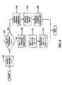
- FIG. 4 is a flowchart illustrating a method of operation for the dynamic tactical steering feedback system
- FIG. 5 is a flowchart illustrating a method of operation for the dynamic tactical steering feedback system.
- FIG. 6 is a flowchart illustrating a method of operation for the dynamic tactical steering feedback system.
- a turf maintenance vehicle i.e., a grounds keeping vehicle
- the mower 10 is a riding mower that generally includes a frame 12, a turf maintenance implement system 13, and a ground traction system generally indicated at 14.
- a turf maintenance vehicle including, for instance, mowers, groomers, sand rakes, aerators, utility vehicles and other turf maintenance equipment, having a power-assisted steering system.
- the turf maintenance implement system 13 is supported by the frame 12 and can be of any suitable type for turf maintenance purposes.
- the turf maintenance implement system 13 includes a plurality of reel cutters 17 for cutting grass or for other turf maintenance operations.
- the turf maintenance implement system 13 can include any suitable implement, including, for instance, mowing implements, grooming implements, raking implements, aerating implements, and other turf maintenance implements.
- the ground traction system 14 supports the frame 12 and provides propulsion and steering for the mower 10.
- the ground transportation system 14 includes a plurality of front wheels 16, which are driven to propel the mower 10, and a rear wheel 18, which can turn relative to the frame 12 to thereby steer the mower 10.
- the ground traction system 14 includes a brake, schematically indicated at 20.
- the brake 20 can be of any suitable type for reducing the ground speed of the mower 10.
- the mower 10 includes a power delivery system generally indicated at 15.
- the power delivery system 15 can be of any suitable type for generating power and transmitting power to the ground traction system 14 and/or the turf maintenance implement system 13.
- the power delivery system 15 can include an internal combustion engine for generating mechanical or electrical energy, a plurality of batteries, or a combination of the two.
- the power delivery system 15 generates and delivers power to the ground traction system 14 to thereby propel the mower.
- the power delivery system 15 delivers power to the turf maintenance implement system 13 to thereby rotate the reel cutters 17.
- the power delivery system 15 also includes a speed limiter schematically indicated at 22.
- a speed limit i.e., a top speed
- the speed limiter 22 is operatively coupled to a throttle (not shown) to thereby limit the power available to the ground traction system 14.
- the speed limiter 22 is programmed logic that determines the amount of power delivered from the power delivery system 15 to the ground traction system 14.
- the mower 10 also includes a steering wheel assembly generally indicated at 24.
- the steering wheel assembly 24 includes a steering wheel 26, a shaft 28 extending from the steering wheel 26 and a steering resistance device 30.
- the steering resistance device 30 is operatively coupled to the shaft 28. As a user turns the steering wheel 26, the shaft 28 rotates about its axis, and the steering resistance device 30 provides a predetermined level of turning resistance against rotation of the shaft 28.
- the steering resistance device 30 includes a magnetorheological fluid 25 and an electromagnet 27 ( FIG. 3 ).
- the magnetorheological fluid 25 can be a known fluid that includes magnetic-field-susceptible particles (e.g., carbonyl iron, powdered iron, iron/cobalt alloys, nickel alloys, etc.) suspended in a liquid vehicle (e.g., mineral oil, synthetic hydrocarbon oil, silicone oil, water, glycol, synthetic ester, perfluorinated polyether, etc.) at 20% to 40% by volume.
- the magnetic-field-susceptible particles measure from 1 to 10 microns typically.
- the magnetorheological fluid 25 is Newtonian in the absence of an applied magnetic field, but the fluid 25 increases in viscosity and develops yield strength as a magnetic field is applied. Specifically, when current is increased to the electromagnet 27, a magnetic field increases in strength to thereby affect the properties of the magnetorheological fluid 25. As a result, resistance to rotating the shaft 28 increases.
- the steering resistance device 30 can include any other suitable device, including, for example, a friction clutch assembly that includes a plurality of friction plates that can selectively engage and disengage.
- the friction clutch assembly provides steering resistance via pulse modulation (i.e., by successively engaging and disengaging the friction plates at a predetermined duty cycle).
- the duty cycle of the pulse modulation can be changed in order to change the amount of steering resistance supplied by the friction clutch assembly.
- the steering wheel assembly 24 also includes a steering wheel position sensor 31.
- the steering wheel position sensor 31 detects the rotated position (i.e., the steering angle) of the steering wheel 26. Also, in one embodiment, the steering wheel position sensor 31 detects a change in position of the steering wheel 26.
- the mower 10 also includes a seat 32. The seat 32 is positioned behind the steering wheel assembly 24 and provides a place for a user to sit during operation of the mower 10.
- the mower 10 further includes a dynamic tactical steering feedback system generally indicated at 34.
- the feedback system 34 is largely embodied by a controller 36, which includes programmed logic for effecting the steering and/or speed of the mower 10 as will be described in greater detail below.
- the feedback system 34 also includes a plurality of input devices that detect the status of the mower 10 and that transmit to the controller 36 input signals correlating to the status of the mower 10 as will be described in greater detail below.
- the feedback system 34 includes a plurality of output devices that receive control signals from the controller 36 to thereby change the status of the mower 10 as will be described in greater detail below.
- the rear wheel 18 is rotatably mounted on a fork 38 of the ground traction system 14.
- a shaft 40 is fixed to the fork 38 and extends upward therefrom.
- a gear 42 is fixed to an end of the shaft 40 and is spaced from the fork 38.
- the fork 38, the shaft 40, and the gear 42 are rotatably mounted to a bracket 44, which is fixed to the frame 12 of the mower 10.
- the ground traction system 14 includes an actuator 46, which is in communication with the controller 36.
- the actuator 46 can be of any suitable type, and in one embodiment, the actuator 46 is an electric motor.
- the actuator 46 includes a shaft 48 that is drivingly rotated according to signals transmitted by the controller 36.
- a gear 50 is fixed to the shaft 48, and a belt 52 rotatably engages the gears 42, 50.
- the controller 36 transmits an output signal to the actuator 46 so as to vary the amount of rotation of the output shaft 48, which causes rotation of the gear 42, shaft 40 and fork 38.
- the controller 36 varies the current supplied to the actuator 46, to thereby vary the amount of turning of the rear steering wheel 18. As such, the rear wheel 18 is turned (i.e., the steering angle changes) according to the output signal transmitted from the controller 36.
- the rear wheel 18 has a steering angle limit (i.e., the maximum turning angle of the rear wheel 18 away from a centered, straight direction).
- the controller 36 sets the steering angle limit of the rear steering wheel 18.
- the steering angle limit is variable.
- the controller 36 is in communication with the steering wheel position sensor 31 and receives input signals from the steering wheel position sensor 31 based on the detected steering wheel position.
- the controller 36 generates and transmits an output signal to the actuator 46 based on the input signal received from the steering wheel position sensor 31. Accordingly, when a user turns the steering wheel 26, the steering wheel position sensor 31 detects the steering wheel position, the steering wheel position sensor 31 transmits an input signal to the controller 36 based on the position of the steering wheel 26, and the controller 36 transmits an output signal to the actuator 46. Then, the actuator 46 drivingly rotates the shaft 48 to thereby produce the desired amount of turning of the rear wheel 18.
- the term “steering ratio” generally refers to the ratio between the amount of turning input of the steering wheel 26 and the amount of turning output of the rear wheel 18.
- the feedback system 34 varies the steering ratio of the mower 10. For instance, when the feedback system 34 is set for a higher turning ratio, more turning of the steering wheel 26 is needed to produce a certain amount of turning of the rear wheel 18. Also, when the feedback system 34 is set for a lower turning ratio, less turning of the steering wheel 26 is needed to produce the same amount of turning of the rear wheel 18.
- the mower 10 described above includes a drive-by-wire system for steering control.
- the mower 10 could depend on one or more mechanical linkages operatively coupling the steering wheel assembly 24 and the ground traction system 14 without departing from the scope of the present disclosure.
- the dynamic tactical steering feedback system 34 generally detects the ground speed and/or the steering angle of the mower 10. An input signal is generated based on this information, and the input signal is transmitted to the controller 36. Then, the controller 36 outputs a control signal to one or more output devices to thereby change the steering resistance, the turning ratio, the speed limit, the ground speed, and/or the turning angle limit of the mower 10 based on the detected steering angle and/or ground speed of the mower 10. As such, the feedback system 34 improves the driver control of the mower 10.
- the mower 10 includes a ground speed sensor 60 that detects the ground speed of the mower 10.
- the ground speed sensor 60 can be of any suitable type.
- the steering angle of the mower 10 can be detected in any suitable fashion.
- the steering angle of the mower 10 is detected by the steering wheel position sensor 31.
- the mower 10 includes a steering angle sensor 33 ( FIG. 2 ), which is operatively mounted to the ground traction system 14. More, specifically, the steering angle sensor 33 detects the position of the rear wheel 18. It will be appreciated that the steering angle of the mower 10 can be detected by one or both of the sensors 31,33.
- the feedback system 34 automatically changes the steering resistance of the mower 10.
- the ground speed is detected by the ground speed sensor 60, and a correlative input signal is transmitted to the controller 36.
- the controller 36 determines that the detected ground speed is above a predetermined threshold level (i.e., the mower 10 is traveling at a relatively high rate of speed)
- the controller 36 transmits a control signal to the steering resistance device 30 to increase the steering resistance against turning of the steering wheel 26.
- the controller 36 determines that the ground speed is below the predetermined threshold speed (i.e., the mower 10 is traveled at a relatively low rate of speed)
- the controller 36 transmits a control signal to the steering resistance device 30 to decrease the steering resistance against turning of the steering wheel 26.
- the controller 36 transmits a control signal to the steering resistance device 30 to decrease the steering resistance against turning of the steering wheel 26.
- the steering ratio is automatically changed by the feedback system 34.
- the ground speed sensor 60 detects the ground speed of the mower 10, and transmits a correlative input signal to the controller 36. If the controller 36 determines that the ground speed is above a predetermined threshold speed (i.e., the mower 10 is traveling at a relatively high rate of speed), the controller 36 outputs a control signal to the actuator 46 for increasing the steering ratio. Also, if the controller 36 determines that the ground speed of the mower 10 is below the predetermined threshold speed (i.e., the mower 10 is traveling at a relatively low rate of speed), the controller 36 outputs a control signal to the actuator 46 for decreasing the steering ratio of the mower 10.
- the steering angle limit is automatically changed by the feedback device 34.
- the ground speed is detected by the ground speed sensor 60, and a correlative input signal is transmitted to the controller 36. If the controller 36 determines that the ground speed is above a predetermined threshold speed (i.e., the mower 10 is traveling at a relatively high rate of speed), the controller 36 decreases the turning angle limit and allows for turning of the rear wheel 18 only within that reduced limit. If the controller 36 determines that the ground speed is less than the predetermined threshold speed (i.e., the mower 10 is traveling at a relatively low rate of speed), the controller 36 increases the turning angle limit and allows for turning of the rear wheel 18 within the increased limit.
- a predetermined threshold speed i.e., the mower 10 is traveling at a relatively high rate of speed
- the controller 36 decreases the turning angle limit and allows for turning of the rear wheel 18 only within that reduced limit. If the controller 36 determines that the ground speed is less than the predetermined threshold speed (i.e., the mower 10 is traveling at a relatively low rate of
- the maximum amount of turning of the rear wheel 18 in a high speed situation is 30 degrees away from the centerline of the mower 10, and the maximum tire angle in a low speed situation is 52 degrees. It will be appreciated that there could be a plurality of threshold speeds and a corresponding number of steering angle limits set by the controller 36. Accordingly, when the mower 10 is traveling quickly, the amount of turning of the rear wheel 18 is limited, and loss of control of the mower 18 due to a high speed, sharp turn is less likely. Also, when the mower 10 is traveling slowly, the mower 10 can be turned more sharply to improve maneuverability.
- the feedback device 34 automatically changes the speed limit of the mower 10.
- the steering angle is detected by the steering wheel position sensor 31 and/or the steering angle sensor 33, and a correlative input signal is transmitted to the controller 36. If the steering angle is beyond a predetermined threshold angle (i.e., a relatively sharp turn is detected), the controller 36 outputs a control signal to the speed limiter 22 to thereby reduce the maximum speed of the mower 10. If the controller 36 determines that the steering angle is below a predetermined threshold angle (i.e., the mower 10 is traveling in a generally straight direction), then the controller 36 outputs a control signal to the speed limiter 22 to increase the maximum speed of the mower 10.
- the controller 36 there could be a plurality of threshold angles and a corresponding number of speed limits set by the controller 36.
- the speed limit of the mower 10 when turning of the mower 10 is detected the speed limit of the mower 10 is set at five miles per hour (5mph).
- the mower 10 can travel at a higher rate of speed when traveling straight, and the speed limit of the mower 10 is reduced when turning. Accordingly, control of the mower 10 is improved.
- the feedback device 34 automatically changes the ground speed of the mower 10. More specifically, the ground speed sensor 60 detects the ground speed of the mower 10, and the steering angle is detected by the steering wheel position sensor 31 and/or the steering angle sensor 33. A correlative input signal is transmitted to the controller 36, and the controller 36 outputs a control signal to either maintain the detected ground speed or reduce the ground speed. More specifically, if the controller 36 determines that the steering angle is beyond a predetermined threshold angle (i.e., a tight turn is detected) and the ground speed is above a predetermined threshold level (i.e., the mower 10 is traveling relatively fast), the controller 36 outputs a control signal to the brake 20 to activate to slow the mower 10.
- a predetermined threshold angle i.e., a tight turn is detected
- the controller 36 outputs a control signal to the brake 20 to activate to slow the mower 10.
- the brake 20 is automatically activated to reduce the mower speed below five miles per hour (5mph). As such, the user is less likely to lose control of the mower 10 due to a high speed, tight turn situation.
- the method begins at block 110 in which the ground speed of the mower 10 is detected by the ground speed sensor 60. Then, in decision block 112, the controller 36 determines whether the mower 10 is traveling above the threshold speed. If the result is negative, then the steering resistance is reduced at 114, the steering ratio is decreased at 116, and the turning angle limit is increased at 118 as discussed above. If the result of the decision in decision block 112 is positive, then the steering resistance is increased at 120, the steering ratio is increased at 122, and the turning angle limit is decreased at 124 as discussed above. It will be appreciated that the feedback system 34 can, according to various embodiments, vary only one or multiple ones of the steering resistance, steer ratio, and turning angle limit based on the detected ground speed without departing from the scope of the present disclosure.
- the method begins at 126, in which the steering angle of the mower 10 is detected as discussed above. Then, in decision block 128, the controller 36 determines whether the steering angle is beyond the threshold angle. If the result of the decision is negative, at 130, the speed limit of the mower 10 is reduced. If the result of the decision at decision block 128 is positive, then the speed limit of the mower 10 is increased in step 132.
- the method begins at 140 in which the ground speed of the mower 10 is detected. Then, at 142, the steering angle of the mower 10 is detected. Next, in decision block 144, the controller 36 determines whether the detected speed is above the threshold speed and whether the steering angle is beyond the threshold angle. If the results of the decision are negative, the process reverts back to blocks 140 and 142. However, if the results of the decision block 144 is positive, the controller 36 outputs the control signal to the brake 20, such that the brake 20 is automatically applied in step 146.
- the dynamic tactical steering feedback system 34 improves driver control of the mower 10. It will also be appreciated that the system 34 can be configured as a feedback control system such that an output signal from the respective output device (i.e., the steering resistance device 30, the actuator 46, etc.) is transmitted back to the controller 36 to control the dynamic behavior of the mower 10.
- the respective output device i.e., the steering resistance device 30, the actuator 46, etc.
Landscapes
- Engineering & Computer Science (AREA)
- Mechanical Engineering (AREA)
- Transportation (AREA)
- Chemical & Material Sciences (AREA)
- Combustion & Propulsion (AREA)
- Environmental Sciences (AREA)
- Life Sciences & Earth Sciences (AREA)
- Automation & Control Theory (AREA)
- Guiding Agricultural Machines (AREA)
- Harvester Elements (AREA)
- Steering Control In Accordance With Driving Conditions (AREA)
- Control Of Driving Devices And Active Controlling Of Vehicle (AREA)
- Regulating Braking Force (AREA)
- Power Steering Mechanism (AREA)
Abstract
Description
- The present disclosure relates to a turf maintenance vehicle and, more particularly, relates to a dynamic tactical steering feedback system for a turf maintenance vehicle.
- The statements in this section merely provide background information related to the present disclosure and may not constitute prior art.
- Turf maintenance vehicles (i.e., grounds keeping vehicles) are used for grounds keeping purposes on golf courses, parks, and other locations. Ride-on mowers, for instance, typically include a power delivery system (e.g., an internal combustion engine, batteries, etc.), a ground traction system that receives power from the power delivery system, and a steering wheel assembly that allows the user to steer the mower. These mowers can move at fairly high speeds and have a high degree of maneuverability. Traveling at high speed and/or through tight turns, may require more skill to control the vehicle than when traveling at lower speed and/or in a straight line. On sloped or uneven terrain, even more skill may be required for optimal operation.
- A dynamic tactical feedback system for a turf maintenance vehicle is disclosed. The system includes an input device that detects a steering angle and/or a ground speed of the turf maintenance vehicle. The input device transmits an input signal correlative to the steering angle and/or the ground speed of the turf maintenance vehicle. The system also includes an output device that affects the steering resistance, the turning ratio, the speed limit, the ground speed and/or the turning angle limit of the turf maintenance vehicle. Furthermore, the system includes a controller that receives the input signal and outputs a control signal to the output device based on the input signal so as to change the steering resistance, the turning ratio, the speed limit, the ground speed and/or the turning angle limit of the turf maintenance vehicle based on the input signal.
- In another aspect, a method of controlling a turf maintenance vehicle is disclosed. The method includes detecting a steering angle and/or a ground speed of the turf maintenance vehicle. The method also includes transmitting an input signal to a controller. The input signal correlates to the steering angle and/or the ground speed of the turf maintenance vehicle. Furthermore, the method includes changing a steering resistance, a turning ratio, a speed limit, a ground speed, and a turning angle limit of the turf maintenance vehicle according to the control signal that is transmitted from the controller and that is based on the input signal.
- In still another aspect, a method of controlling a turf maintenance vehicle is disclosed. The method includes detecting a ground speed of the turf maintenance vehicle and determining whether the ground speed is above a predetermined threshold level. The method also includes transmitting an input signal to a controller. The input signal correlates to the ground speed of the turf maintenance vehicle. Also, the method includes increasing a steering resistance with a magnetorheological fluid, increasing a turning ratio, and decreasing a turning angle limit of the turf maintenance vehicle when the ground speed is above the predetermined threshold level.
- Moreover, a method of controlling a turf maintenance vehicle is disclosed. The method includes detecting a steering angle of the turf maintenance vehicle according to a position of the steering wheel assembly and/or a ground traction system. The method also includes transmitting an input signal to a controller. The input signal correlates to the steering angle of the turf maintenance vehicle. Furthermore, the method includes changing a speed limit and/or a ground speed of the turf maintenance vehicle according to a control signal that is transmitted from the controller and that is based on the input signal.
- In an additional aspect, a turf maintenance vehicle is disclosed that includes a frame, a turf maintenance implement supported by the frame, and a ground traction system including a plurality of wheels supporting the frame. The turf maintenance vehicle further includes a power delivery system that delivers power to the turf maintenance implement and/or the ground traction system. Moreover, the turf maintenance vehicle includes an input device that detects a steering angle and/or a ground speed of the turf maintenance vehicle and that transmits an input signal correlative to the steering angle and/or the ground speed of the turf maintenance vehicle. Furthermore, the turf maintenance vehicle includes an output device that affects a steering resistance, a turning ratio, a speed limit, the ground speed, and/or a turning angle limit of the turf maintenance vehicle. The turf maintenance vehicle additionally includes a controller that receives the input signal and outputs a control signal to the output device based on the input signal so as to change the steering resistance, the turning ratio, the speed limit, the ground speed, and/or the turning angle limit of the turf maintenance vehicle based on the input signal.
- In still another aspect, a turf maintenance vehicle is disclosed that includes a frame, a turf maintenance implement supported by the frame, and a ground traction system including a plurality of wheels supporting the frame. The turf maintenance vehicle additionally includes a power delivery system that delivers power to the turf maintenance implement and/or the ground traction system. The turf maintenance vehicle also includes a steering system that changes a direction of travel of the turf maintenance vehicle. Furthermore, the turf maintenance vehicle includes a ground speed sensor that detects a ground speed of the turf maintenance vehicle and a steering angle sensor that detects a steering angle of the steering system. Additionally, the turf maintenance vehicle includes a controller that changes a steering resistance of the steering system, the turning ratio of the steering system, the speed limit of the ground traction system, the ground speed of the ground traction system, and/or the turning angle limit of the steering system based on the ground speed detected by the ground speed sensor and/or the steering angle detected by the steering angle sensor.
- Further areas of applicability will become apparent from the description provided herein. It should be understood that the description and specific examples are intended for purposes of illustration only and are not intended to limit the scope of the present disclosure.
- The drawings described herein are for illustration purposes only and are not intended to limit the scope of the present disclosure in any way.
-
FIG. 1 is a perspective view of a turf maintenance vehicle according to the present disclosure; -
FIG. 2 is a schematic view of a dynamic tactical steering feedback system for the turf maintenance vehicle ofFIG. 1 ; -
FIG. 3 is a schematic view of the dynamic tactical steering feedback system for the turf maintenance vehicle ofFIG. 1 ; -
FIG. 4 is a flowchart illustrating a method of operation for the dynamic tactical steering feedback system; -
FIG. 5 is a flowchart illustrating a method of operation for the dynamic tactical steering feedback system; and -
FIG. 6 is a flowchart illustrating a method of operation for the dynamic tactical steering feedback system. - The following description is merely exemplary in nature and is not intended to limit the present disclosure, application, or uses. It should be understood that throughout the drawings, corresponding reference numerals indicate like or corresponding parts and features.
- Referring initially
FIG. 1 , a turf maintenance vehicle (i.e., a grounds keeping vehicle), such as amower 10 is illustrated. In the embodiment shown, themower 10 is a riding mower that generally includes aframe 12, a turfmaintenance implement system 13, and a ground traction system generally indicated at 14. It will be understood by one skilled in the art that the teachings herein are applicable to any suitable turf maintenance vehicle, including, for instance, mowers, groomers, sand rakes, aerators, utility vehicles and other turf maintenance equipment, having a power-assisted steering system. - The turf
maintenance implement system 13 is supported by theframe 12 and can be of any suitable type for turf maintenance purposes. In some embodiments, the turfmaintenance implement system 13 includes a plurality ofreel cutters 17 for cutting grass or for other turf maintenance operations. However, it will be appreciated that the turfmaintenance implement system 13 can include any suitable implement, including, for instance, mowing implements, grooming implements, raking implements, aerating implements, and other turf maintenance implements. - The
ground traction system 14 supports theframe 12 and provides propulsion and steering for themower 10. In the embodiment shown, theground transportation system 14 includes a plurality offront wheels 16, which are driven to propel themower 10, and arear wheel 18, which can turn relative to theframe 12 to thereby steer themower 10. Also, theground traction system 14 includes a brake, schematically indicated at 20. Thebrake 20 can be of any suitable type for reducing the ground speed of themower 10. - Moreover, the
mower 10 includes a power delivery system generally indicated at 15. The power delivery system 15 can be of any suitable type for generating power and transmitting power to theground traction system 14 and/or the turfmaintenance implement system 13. For instance, the power delivery system 15 can include an internal combustion engine for generating mechanical or electrical energy, a plurality of batteries, or a combination of the two. As such, the power delivery system 15 generates and delivers power to theground traction system 14 to thereby propel the mower. Also, in one embodiment, the power delivery system 15 delivers power to the turf maintenance implementsystem 13 to thereby rotate thereel cutters 17. - In the embodiment shown, the power delivery system 15 also includes a speed limiter schematically indicated at 22. Generally speaking, a speed limit (i.e., a top speed) of the
mower 10 is set according to thespeed limiter 22. In various embodiments, thespeed limiter 22 is operatively coupled to a throttle (not shown) to thereby limit the power available to theground traction system 14. Also, in various embodiments, thespeed limiter 22 is programmed logic that determines the amount of power delivered from the power delivery system 15 to theground traction system 14. - The
mower 10 also includes a steering wheel assembly generally indicated at 24. Thesteering wheel assembly 24 includes asteering wheel 26, ashaft 28 extending from thesteering wheel 26 and asteering resistance device 30. Thesteering resistance device 30 is operatively coupled to theshaft 28. As a user turns thesteering wheel 26, theshaft 28 rotates about its axis, and thesteering resistance device 30 provides a predetermined level of turning resistance against rotation of theshaft 28. - In some embodiments, the
steering resistance device 30 includes a magnetorheological fluid 25 and an electromagnet 27 (FIG. 3 ). The magnetorheological fluid 25 can be a known fluid that includes magnetic-field-susceptible particles (e.g., carbonyl iron, powdered iron, iron/cobalt alloys, nickel alloys, etc.) suspended in a liquid vehicle (e.g., mineral oil, synthetic hydrocarbon oil, silicone oil, water, glycol, synthetic ester, perfluorinated polyether, etc.) at 20% to 40% by volume. In some embodiments, the magnetic-field-susceptible particles measure from 1 to 10 microns typically. There can also include additives such as suspending agents, thixotropes, anti-wear and anti-corrosion additives, friction modifiers, etc. The magnetorheological fluid 25 is Newtonian in the absence of an applied magnetic field, but the fluid 25 increases in viscosity and develops yield strength as a magnetic field is applied. Specifically, when current is increased to theelectromagnet 27, a magnetic field increases in strength to thereby affect the properties of the magnetorheological fluid 25. As a result, resistance to rotating theshaft 28 increases. - It will be appreciated that the
steering resistance device 30 can include any other suitable device, including, for example, a friction clutch assembly that includes a plurality of friction plates that can selectively engage and disengage. The friction clutch assembly provides steering resistance via pulse modulation (i.e., by successively engaging and disengaging the friction plates at a predetermined duty cycle). The duty cycle of the pulse modulation can be changed in order to change the amount of steering resistance supplied by the friction clutch assembly. - The
steering wheel assembly 24 also includes a steeringwheel position sensor 31. The steeringwheel position sensor 31 detects the rotated position (i.e., the steering angle) of thesteering wheel 26. Also, in one embodiment, the steeringwheel position sensor 31 detects a change in position of thesteering wheel 26. Themower 10 also includes aseat 32. Theseat 32 is positioned behind thesteering wheel assembly 24 and provides a place for a user to sit during operation of themower 10. - The
mower 10 further includes a dynamic tactical steering feedback system generally indicated at 34. Thefeedback system 34 is largely embodied by acontroller 36, which includes programmed logic for effecting the steering and/or speed of themower 10 as will be described in greater detail below. Thefeedback system 34 also includes a plurality of input devices that detect the status of themower 10 and that transmit to thecontroller 36 input signals correlating to the status of themower 10 as will be described in greater detail below. Furthermore, thefeedback system 34 includes a plurality of output devices that receive control signals from thecontroller 36 to thereby change the status of themower 10 as will be described in greater detail below. - Referring now to
FIGS. 2 and3 , steering of themower 10 will be explained in greater detail. As shown, therear wheel 18 is rotatably mounted on afork 38 of theground traction system 14. A shaft 40 is fixed to thefork 38 and extends upward therefrom. Agear 42 is fixed to an end of the shaft 40 and is spaced from thefork 38. Also, thefork 38, the shaft 40, and thegear 42 are rotatably mounted to a bracket 44, which is fixed to theframe 12 of themower 10. Also, theground traction system 14 includes anactuator 46, which is in communication with thecontroller 36. Theactuator 46 can be of any suitable type, and in one embodiment, theactuator 46 is an electric motor. Theactuator 46 includes a shaft 48 that is drivingly rotated according to signals transmitted by thecontroller 36. Agear 50 is fixed to the shaft 48, and abelt 52 rotatably engages thegears - As will be described in greater detail below, the
controller 36 transmits an output signal to theactuator 46 so as to vary the amount of rotation of the output shaft 48, which causes rotation of thegear 42, shaft 40 andfork 38. In one embodiment, thecontroller 36 varies the current supplied to theactuator 46, to thereby vary the amount of turning of therear steering wheel 18. As such, therear wheel 18 is turned (i.e., the steering angle changes) according to the output signal transmitted from thecontroller 36. - It will also be appreciated that the
rear wheel 18 has a steering angle limit (i.e., the maximum turning angle of therear wheel 18 away from a centered, straight direction). In various embodiments, thecontroller 36 sets the steering angle limit of therear steering wheel 18. Furthermore, in various embodiments, the steering angle limit is variable. - The
controller 36 is in communication with the steeringwheel position sensor 31 and receives input signals from the steeringwheel position sensor 31 based on the detected steering wheel position. Thecontroller 36 generates and transmits an output signal to theactuator 46 based on the input signal received from the steeringwheel position sensor 31. Accordingly, when a user turns thesteering wheel 26, the steeringwheel position sensor 31 detects the steering wheel position, the steeringwheel position sensor 31 transmits an input signal to thecontroller 36 based on the position of thesteering wheel 26, and thecontroller 36 transmits an output signal to theactuator 46. Then, theactuator 46 drivingly rotates the shaft 48 to thereby produce the desired amount of turning of therear wheel 18. - As is generally known, the term "steering ratio" generally refers to the ratio between the amount of turning input of the
steering wheel 26 and the amount of turning output of therear wheel 18. As will be discussed, thefeedback system 34 varies the steering ratio of themower 10. For instance, when thefeedback system 34 is set for a higher turning ratio, more turning of thesteering wheel 26 is needed to produce a certain amount of turning of therear wheel 18. Also, when thefeedback system 34 is set for a lower turning ratio, less turning of thesteering wheel 26 is needed to produce the same amount of turning of therear wheel 18. - It will be understood that the
mower 10 described above includes a drive-by-wire system for steering control. However, it will be appreciated that themower 10 could depend on one or more mechanical linkages operatively coupling thesteering wheel assembly 24 and theground traction system 14 without departing from the scope of the present disclosure. - As will be described in greater detail below, the dynamic tactical
steering feedback system 34 generally detects the ground speed and/or the steering angle of themower 10. An input signal is generated based on this information, and the input signal is transmitted to thecontroller 36. Then, thecontroller 36 outputs a control signal to one or more output devices to thereby change the steering resistance, the turning ratio, the speed limit, the ground speed, and/or the turning angle limit of themower 10 based on the detected steering angle and/or ground speed of themower 10. As such, thefeedback system 34 improves the driver control of themower 10. In various embodiments, themower 10 includes aground speed sensor 60 that detects the ground speed of themower 10. Theground speed sensor 60 can be of any suitable type. - The steering angle of the
mower 10 can be detected in any suitable fashion. In various embodiments, the steering angle of themower 10 is detected by the steeringwheel position sensor 31. In other embodiments, themower 10 includes a steering angle sensor 33 (FIG. 2 ), which is operatively mounted to theground traction system 14. More, specifically, the steering angle sensor 33 detects the position of therear wheel 18. It will be appreciated that the steering angle of themower 10 can be detected by one or both of thesensors 31,33. - In some embodiments, the
feedback system 34 automatically changes the steering resistance of themower 10. First, the ground speed is detected by theground speed sensor 60, and a correlative input signal is transmitted to thecontroller 36. In one embodiment, if thecontroller 36 determines that the detected ground speed is above a predetermined threshold level (i.e., themower 10 is traveling at a relatively high rate of speed), thecontroller 36 transmits a control signal to thesteering resistance device 30 to increase the steering resistance against turning of thesteering wheel 26. Also, in other embodiments, if thecontroller 36 determines that the ground speed is below the predetermined threshold speed (i.e., themower 10 is traveled at a relatively low rate of speed), thecontroller 36 transmits a control signal to thesteering resistance device 30 to decrease the steering resistance against turning of thesteering wheel 26. It will be appreciated that there could be a plurality of threshold speeds and a corresponding number of steering resistance levels. Thus, when themower 10 is traveling quickly, the user is less likely to inadvertently turn thewheel 26 because it takes more force to do so. Also, when themower 10 is traveling slower, thesteering wheel 26 can be turned more easily by the user to improve maneuverability of themower 10. Thus, driver control is improved. - In other embodiments, the steering ratio is automatically changed by the
feedback system 34. Theground speed sensor 60 detects the ground speed of themower 10, and transmits a correlative input signal to thecontroller 36. If thecontroller 36 determines that the ground speed is above a predetermined threshold speed (i.e., themower 10 is traveling at a relatively high rate of speed), thecontroller 36 outputs a control signal to theactuator 46 for increasing the steering ratio. Also, if thecontroller 36 determines that the ground speed of themower 10 is below the predetermined threshold speed (i.e., themower 10 is traveling at a relatively low rate of speed), thecontroller 36 outputs a control signal to theactuator 46 for decreasing the steering ratio of themower 10. It will be appreciated that there could be a plurality of threshold speeds and a corresponding number of steering ratios set by thecontroller 36. Thus, when themower 10 is traveling quickly, inadvertent turning of thesteering wheel 26 is less likely to turn therear wheel 18 because the steering ratio is increased. Also, when themower 10 is traveling slower, therear wheel 18 is more responsive to turning of thesteering wheel 26 for improved maneuverability. Accordingly, control of themower 10 is improved. - In other embodiments, the steering angle limit is automatically changed by the
feedback device 34. The ground speed is detected by theground speed sensor 60, and a correlative input signal is transmitted to thecontroller 36. If thecontroller 36 determines that the ground speed is above a predetermined threshold speed (i.e., themower 10 is traveling at a relatively high rate of speed), thecontroller 36 decreases the turning angle limit and allows for turning of therear wheel 18 only within that reduced limit. If thecontroller 36 determines that the ground speed is less than the predetermined threshold speed (i.e., themower 10 is traveling at a relatively low rate of speed), thecontroller 36 increases the turning angle limit and allows for turning of therear wheel 18 within the increased limit. In other embodiments, the maximum amount of turning of therear wheel 18 in a high speed situation is 30 degrees away from the centerline of themower 10, and the maximum tire angle in a low speed situation is 52 degrees. It will be appreciated that there could be a plurality of threshold speeds and a corresponding number of steering angle limits set by thecontroller 36. Accordingly, when themower 10 is traveling quickly, the amount of turning of therear wheel 18 is limited, and loss of control of themower 18 due to a high speed, sharp turn is less likely. Also, when themower 10 is traveling slowly, themower 10 can be turned more sharply to improve maneuverability. - In other embodiments, the
feedback device 34 automatically changes the speed limit of themower 10. The steering angle is detected by the steeringwheel position sensor 31 and/or the steering angle sensor 33, and a correlative input signal is transmitted to thecontroller 36. If the steering angle is beyond a predetermined threshold angle (i.e., a relatively sharp turn is detected), thecontroller 36 outputs a control signal to thespeed limiter 22 to thereby reduce the maximum speed of themower 10. If thecontroller 36 determines that the steering angle is below a predetermined threshold angle (i.e., themower 10 is traveling in a generally straight direction), then thecontroller 36 outputs a control signal to thespeed limiter 22 to increase the maximum speed of themower 10. It will be appreciated that there could be a plurality of threshold angles and a corresponding number of speed limits set by thecontroller 36. In other embodiments, when turning of themower 10 is detected the speed limit of themower 10 is set at five miles per hour (5mph). Thus, themower 10 can travel at a higher rate of speed when traveling straight, and the speed limit of themower 10 is reduced when turning. Accordingly, control of themower 10 is improved. - Furthermore, in various embodiments, the
feedback device 34 automatically changes the ground speed of themower 10. More specifically, theground speed sensor 60 detects the ground speed of themower 10, and the steering angle is detected by the steeringwheel position sensor 31 and/or the steering angle sensor 33. A correlative input signal is transmitted to thecontroller 36, and thecontroller 36 outputs a control signal to either maintain the detected ground speed or reduce the ground speed. More specifically, if thecontroller 36 determines that the steering angle is beyond a predetermined threshold angle (i.e., a tight turn is detected) and the ground speed is above a predetermined threshold level (i.e., themower 10 is traveling relatively fast), thecontroller 36 outputs a control signal to thebrake 20 to activate to slow themower 10. In other embodiments, when the mower is traveling above five miles per hour (5mph) and the user turns the wheel to turn themower 10 sharply, thebrake 20 is automatically activated to reduce the mower speed below five miles per hour (5mph). As such, the user is less likely to lose control of themower 10 due to a high speed, tight turn situation. - Referring now to
FIG. 4 , a method of automatically changing the steering resistance, steer ratio, and turning angle limit is represented. In the embodiment shown, the method begins atblock 110 in which the ground speed of themower 10 is detected by theground speed sensor 60. Then, in decision block 112, thecontroller 36 determines whether themower 10 is traveling above the threshold speed. If the result is negative, then the steering resistance is reduced at 114, the steering ratio is decreased at 116, and the turning angle limit is increased at 118 as discussed above. If the result of the decision in decision block 112 is positive, then the steering resistance is increased at 120, the steering ratio is increased at 122, and the turning angle limit is decreased at 124 as discussed above. It will be appreciated that thefeedback system 34 can, according to various embodiments, vary only one or multiple ones of the steering resistance, steer ratio, and turning angle limit based on the detected ground speed without departing from the scope of the present disclosure. - Referring now to
FIG. 5 , a method of changing the speed limit of themower 10 is illustrated. The method begins at 126, in which the steering angle of themower 10 is detected as discussed above. Then, indecision block 128, thecontroller 36 determines whether the steering angle is beyond the threshold angle. If the result of the decision is negative, at 130, the speed limit of themower 10 is reduced. If the result of the decision atdecision block 128 is positive, then the speed limit of themower 10 is increased instep 132. - Referring now to
FIG. 6 , a method of automatically changing the ground speed of themower 10 is illustrated. The method begins at 140 in which the ground speed of themower 10 is detected. Then, at 142, the steering angle of themower 10 is detected. Next, in decision block 144, thecontroller 36 determines whether the detected speed is above the threshold speed and whether the steering angle is beyond the threshold angle. If the results of the decision are negative, the process reverts back toblocks controller 36 outputs the control signal to thebrake 20, such that thebrake 20 is automatically applied instep 146. - It will be appreciated that the dynamic tactical
steering feedback system 34 improves driver control of themower 10. It will also be appreciated that thesystem 34 can be configured as a feedback control system such that an output signal from the respective output device (i.e., thesteering resistance device 30, theactuator 46, etc.) is transmitted back to thecontroller 36 to control the dynamic behavior of themower 10. - While the disclosure has been described in the specification and illustrated in the drawings with reference to various embodiments, it will be understood by those skilled in the art that various changes may be made and equivalents may be substituted for elements thereof without departing from the scope of the disclosure as defined in the claims. Furthermore, the mixing and matching of features, steps, elements and/or functions between various embodiments is expressly contemplated herein so that one of ordinary skill in the art would appreciate from this disclosure that features, steps, elements and/or functions of one embodiment may be incorporated into another embodiment as appropriate, unless described otherwise above. Moreover, many modifications may be made to adapt a configuration to the teachings of the disclosure without departing from the essential scope thereof. Therefore, it is intended that the disclosure not be limited to the particular embodiment illustrated by the drawings and described in the specification as the best mode presently contemplated for carrying out this disclosure, but that the disclosure will include any embodiments falling within the foregoing description and the appended claims.
Claims (16)
- A dynamic tactical steering feedback system for a turf maintenance vehicle comprising:an input device that detects at least one of a steering angle or a ground speed of the turf maintenance vehicle and that transmits an input signal correlative to the at least one of the steering angle or the ground speed of the turf maintenance vehicle;an output device that affects at least one of a steering resistance, a turning ratio, a speed limit, the ground speed, or a turning angle limit of the turf maintenance vehicle; anda controller that receives the input signal and outputs a control signal to the output device based on the input signal so as to change the at least one of the steering resistance, the turning ratio, the speed limit, the ground speed, or the turning angle limit of the turf maintenance vehicle based on the input signal.
- The dynamic tactical steering feedback system of claim 1, further comprising a steering wheel assembly, wherein the input device is a steering wheel position sensor operatively coupled to the steering wheel assembly and that detects a position of the steering wheel assembly to detect the steering angle of the turf maintenance vehicle.
- The dynamic tactical steering feedback system of claim 2, further comprising a ground traction system, wherein the output signal includes a turning ratio signal, and wherein the output device is an actuator that changes a turning angle of the traction assembly based on the turning ratio signal.
- The dynamic tactical steering feedback system of claim 1, further comprising a ground traction system, wherein the output device is an actuator that changes the turning angle of the ground traction system, and wherein the actuator receives the control signal from the controller so as to accordingly change the turning angle limit of the turf maintenance vehicle.
- The dynamic tactical steering feedback system of claim 1, further comprising a ground traction system, wherein the input device is a steering angle sensor operatively coupled to the ground traction system and that detects a position of the ground traction system to detect the steering angle of the turf maintenance vehicle.
- The dynamic tactical steering feedback system of claim 1, further comprising a ground traction system, wherein the input device is a ground speed sensor operatively coupled to the ground traction system that detects the ground speed of the motor.
- The dynamic tactical steering feedback system of claim 1, further comprising a steering wheel assembly, wherein the output device is a steering resistance device operatively coupled to the steering wheel assembly, and wherein the steering resistance device changes a resistance-to-turning of the steering wheel assembly to thereby change the steering resistance of the turf maintenance vehicle.
- The dynamic tactical steering feedback system of claim 7, wherein the steering resistance device includes at least one of:a magnetorheological fluid that variably supplies the resistance-to-turning and an electromagnet, and wherein the control signal changes a current supplied to the electromagnet to thereby change the resistance-to-turning supplied by the magnetorheological fluid.; ora friction clutch assembly that includes a plurality of friction plates that selectively engage and disengage, wherein the friction clutch assembly supplies the resistance-to-turning via a pulse modulation, and wherein the control signal changes a duty cycle of the pulse modulation to change the resistance-to-turning supplied by the friction clutch assembly.
- The dynamic tactical steering feedback system of claim 1, further comprising a power delivery system and a ground traction system that receives power from the power delivery system to thereby propel the turf maintenance vehicle, and wherein the output device is a brake system that reduces speed of the turf maintenance vehicle below the speed limit, or a speed limiter of the power delivery system that changes the speed limit of the turf maintenance vehicle.
- A method of controlling a turf maintenance vehicle comprising:detecting at least one of a steering angle or a ground speed of the turf maintenance vehicle;transmitting an input signal to a controller, the input signal correlating to the at least one of the steering angle or the ground speed of the turf maintenance vehicle; andchanging at least one of a steering resistance, a turning ratio, a speed limit, the ground speed, or a turning angle limit of the turf maintenance vehicle according to a control signal that is transmitted from the controller and that is based on the input signal.
- The method of claim 10, wherein the detecting at least one of the steering angle and the ground speed comprises detecting whether the ground speed is above a predetermined threshold speed, and wherein the changing at least one of the steering resistance, the turning ratio, the speed limit, the ground speed, or the turning angle limit comprises at least one of increasing the steering resistance, increasing the turning ratio, or reducing the turning angle limit when the ground speed is above the predetermined threshold speed.
- The method of claim 10, wherein the detecting at least one of the steering angle or the ground speed comprises detecting whether the steering angle is beyond a predetermined threshold angle, and wherein the changing at least one of the steering resistance, the turning ratio, the speed limit, the ground speed, or the turning angle limit comprises decreasing the speed limit when the steering angle is beyond a predetermined threshold angle.
- The method of claim 10, wherein the detecting at least one of the steering angle or the ground speed comprises detecting whether the ground speed is above a predetermined threshold speed and detecting whether the steering angle is beyond a predetermined threshold angle, and wherein the changing at least one of the steering resistance, the turning ratio, the speed limit, the ground speed, or the turning angle limit comprises reducing the ground speed preferably by automatically applying a brake to no higher than the predetermined threshold speed when the ground speed is above the predetermined threshold speed and the steering angle is beyond the predetermined threshold angle.
- The method of claim 10, wherein the detecting at least one of the steering angle and the ground speed of the turf maintenance vehicle comprises detecting the steering angle from at least one of a steering wheel position or a ground traction assembly position.
- The method of claim 10, wherein the changing at least one of the steering resistance, the turning ratio, the speed limit, the ground speed, or the turning angle limit comprises at least one of:changing current sent to an electromagnet to change a magnetic field to thereby change the properties of a magnetorheological fluid to thereby change the steering resistance; orchanging a duty cycle of pulse modulation of a friction clutch assembly to thereby change the steering resistance.
- A turf maintenance vehicle comprising:a frame;a turf maintenance implement supported by the frame;a ground traction system including a plurality of wheels supporting the frame;a power delivery system that delivers power to at least one of the turf maintenance implement or the ground traction system; anda dynamic tactical steering feedback system according to any one of claims 1 to 9.
Applications Claiming Priority (1)
| Application Number | Priority Date | Filing Date | Title |
|---|---|---|---|
| US12/020,831 US7894957B2 (en) | 2008-01-28 | 2008-01-28 | Dynamic tactical steering feedback |
Publications (2)
| Publication Number | Publication Date |
|---|---|
| EP2082916A1 true EP2082916A1 (en) | 2009-07-29 |
| EP2082916B1 EP2082916B1 (en) | 2012-03-14 |
Family
ID=40548044
Family Applications (1)
| Application Number | Title | Priority Date | Filing Date |
|---|---|---|---|
| EP08169177A Active EP2082916B1 (en) | 2008-01-28 | 2008-11-14 | Dynamic tactical steering feedback |
Country Status (3)
| Country | Link |
|---|---|
| US (1) | US7894957B2 (en) |
| EP (1) | EP2082916B1 (en) |
| JP (1) | JP5399724B2 (en) |
Cited By (3)
| Publication number | Priority date | Publication date | Assignee | Title |
|---|---|---|---|---|
| EP3646695A1 (en) * | 2018-10-30 | 2020-05-06 | Deere & Company | Triplex greensmower open foot platform cover |
| US20220124972A1 (en) * | 2019-07-09 | 2022-04-28 | Nanjing Chervon Industry Co., Ltd. | Riding lawn mower and control method thereof |
| CN114616973A (en) * | 2020-12-11 | 2022-06-14 | 苏州宝时得电动工具有限公司 | Mower and control method of mower |
Families Citing this family (43)
| Publication number | Priority date | Publication date | Assignee | Title |
|---|---|---|---|---|
| US8255126B2 (en) * | 2010-02-26 | 2012-08-28 | Deere & Company | Aerator having flexible frame |
| JP5751465B2 (en) * | 2010-09-29 | 2015-07-22 | 株式会社Ihi | Riding lawn mower vehicle and control method thereof |
| JP5678549B2 (en) * | 2010-09-29 | 2015-03-04 | 株式会社Ihi | Riding lawn mower vehicle and control method thereof |
| US9753436B2 (en) | 2013-06-11 | 2017-09-05 | Apple Inc. | Rotary input mechanism for an electronic device |
| JP6345782B2 (en) | 2013-08-09 | 2018-06-20 | アップル インコーポレイテッド | Tactile switches for electronic devices |
| US10048802B2 (en) | 2014-02-12 | 2018-08-14 | Apple Inc. | Rejection of false turns of rotary inputs for electronic devices |
| US10190891B1 (en) | 2014-07-16 | 2019-01-29 | Apple Inc. | Optical encoder for detecting rotational and axial movement |
| KR102239316B1 (en) | 2014-09-02 | 2021-04-13 | 애플 인크. | Wearable electronic device |
| WO2016141228A1 (en) | 2015-03-05 | 2016-09-09 | Apple Inc. | Optical encoder with direction-dependent optical properties |
| JP6479997B2 (en) | 2015-03-08 | 2019-03-06 | アップル インコーポレイテッドApple Inc. | Compressible seal for rotatable and translatable input mechanism |
| US9908606B1 (en) | 2015-06-23 | 2018-03-06 | Brunswick Corporation | Drive-by-wire control systems and methods for steering a marine vessel |
| US9891651B2 (en) * | 2016-02-27 | 2018-02-13 | Apple Inc. | Rotatable input mechanism having adjustable output |
| US10551798B1 (en) | 2016-05-17 | 2020-02-04 | Apple Inc. | Rotatable crown for an electronic device |
| JP6826377B2 (en) * | 2016-05-27 | 2021-02-03 | 本田技研工業株式会社 | Vehicle steering system |
| US10061399B2 (en) | 2016-07-15 | 2018-08-28 | Apple Inc. | Capacitive gap sensor ring for an input device |
| US10019097B2 (en) | 2016-07-25 | 2018-07-10 | Apple Inc. | Force-detecting input structure |
| US10457370B1 (en) * | 2016-11-18 | 2019-10-29 | Brunswick Corporation | Marine steering system and method of providing steering feedback |
| JP6634007B2 (en) * | 2016-12-26 | 2020-01-22 | 本田技研工業株式会社 | Lawn mower |
| US10664074B2 (en) | 2017-06-19 | 2020-05-26 | Apple Inc. | Contact-sensitive crown for an electronic watch |
| US10962935B1 (en) | 2017-07-18 | 2021-03-30 | Apple Inc. | Tri-axis force sensor |
| JP6972924B2 (en) * | 2017-10-27 | 2021-11-24 | コベルコ建機株式会社 | Driving route guidance device |
| DE102018205674A1 (en) * | 2018-04-13 | 2019-10-17 | Deere & Company | Method for influencing the steering characteristic of an agricultural tractor |
| US11360440B2 (en) | 2018-06-25 | 2022-06-14 | Apple Inc. | Crown for an electronic watch |
| US11561515B2 (en) | 2018-08-02 | 2023-01-24 | Apple Inc. | Crown for an electronic watch |
| US11181863B2 (en) | 2018-08-24 | 2021-11-23 | Apple Inc. | Conductive cap for watch crown |
| CN209560398U (en) | 2018-08-24 | 2019-10-29 | 苹果公司 | digital watch |
| US12259690B2 (en) | 2018-08-24 | 2025-03-25 | Apple Inc. | Watch crown having a conductive surface |
| US11194298B2 (en) | 2018-08-30 | 2021-12-07 | Apple Inc. | Crown assembly for an electronic watch |
| CN209625187U (en) | 2018-08-30 | 2019-11-12 | 苹果公司 | Electronic Watches and Electronic Devices |
| CN109018068A (en) * | 2018-09-05 | 2018-12-18 | 天津同捷汽车设计有限公司 | A kind of vehicle that capableing of transverse shifting and its control method |
| US11785885B2 (en) * | 2019-01-31 | 2023-10-17 | The Toro Company | Mower with ganged reel cutting units having automatic clip control in both straight ahead motion and in turns |
| US11194299B1 (en) * | 2019-02-12 | 2021-12-07 | Apple Inc. | Variable frictional feedback device for a digital crown of an electronic watch |
| JP7259574B2 (en) * | 2019-06-17 | 2023-04-18 | 株式会社ジェイテクト | Control device and steering device |
| US12122448B1 (en) | 2019-09-18 | 2024-10-22 | Parker-Hannifin Corporation | Zero turning radius vehicle and drive system for zero turning radius vehicle |
| US11550268B2 (en) | 2020-06-02 | 2023-01-10 | Apple Inc. | Switch module for electronic crown assembly |
| KR102350468B1 (en) * | 2020-07-20 | 2022-01-12 | 강기수 | The Tension adjustment structure of the driven wheel for rotating the track belt of a small electric vehicle for transportation |
| US12092996B2 (en) | 2021-07-16 | 2024-09-17 | Apple Inc. | Laser-based rotation sensor for a crown of an electronic watch |
| US12329067B2 (en) | 2021-07-26 | 2025-06-17 | Cnh Industrial America Llc | Reel power system |
| WO2023039874A1 (en) | 2021-09-18 | 2023-03-23 | Nanjing Chervon Industry Co., Ltd. | Riding lawn mower, display interface of a power tool and riding machine |
| CN118160211A (en) * | 2021-10-15 | 2024-06-07 | 南京泉峰科技有限公司 | Riding lawn mower |
| US12189347B2 (en) | 2022-06-14 | 2025-01-07 | Apple Inc. | Rotation sensor for a crown of an electronic watch |
| US12596334B2 (en) | 2023-02-07 | 2026-04-07 | Apple Inc. | Crown for an electronic watch |
| US12447829B2 (en) | 2023-12-19 | 2025-10-21 | Textron Innovations Inc. | Controlling vehicles based on current locations and current motion characteristics |
Citations (5)
| Publication number | Priority date | Publication date | Assignee | Title |
|---|---|---|---|---|
| US6456925B1 (en) * | 2000-09-11 | 2002-09-24 | Deere & Company | Vehicle driven wheel speed control system |
| EP1541446A2 (en) * | 2003-12-10 | 2005-06-15 | Deere & Company | Utility vehicle |
| WO2007014030A2 (en) * | 2005-07-22 | 2007-02-01 | Infinitrak Llc | Steering systems, steering and speed coordination systems, and associated vehicles |
| EP1816052A1 (en) * | 2001-08-06 | 2007-08-08 | JTEKT Corporation | Power steering apparatus |
| DE102006017406A1 (en) * | 2006-04-13 | 2007-10-18 | Zf Lenksysteme Gmbh | Motor vehicle`s superposition steering system operating method, involves limiting gradient of transmission ratio between steering wheel angle and wheel steering angle after detecting condition of vehicle cornering with constant curve radius |
Family Cites Families (5)
| Publication number | Priority date | Publication date | Assignee | Title |
|---|---|---|---|---|
| US5497604A (en) * | 1994-02-03 | 1996-03-12 | The Toro Company | Supervisor switch for turf mower |
| US6082084A (en) * | 1995-11-13 | 2000-07-04 | Ransomes America Corporation | Electric riding mower with electric steering system |
| JP4026887B2 (en) * | 1997-07-24 | 2007-12-26 | 本田技研工業株式会社 | Electric power steering device |
| WO2006027875A1 (en) * | 2004-08-06 | 2006-03-16 | National University Corporation Tokyo University Of Agriculture And Technology | Front wheel steering control device |
| JP4760015B2 (en) * | 2004-12-24 | 2011-08-31 | 日産自動車株式会社 | Vehicle steering system |
-
2008
- 2008-01-28 US US12/020,831 patent/US7894957B2/en active Active
- 2008-11-14 EP EP08169177A patent/EP2082916B1/en active Active
-
2009
- 2009-01-23 JP JP2009013657A patent/JP5399724B2/en not_active Expired - Fee Related
Patent Citations (5)
| Publication number | Priority date | Publication date | Assignee | Title |
|---|---|---|---|---|
| US6456925B1 (en) * | 2000-09-11 | 2002-09-24 | Deere & Company | Vehicle driven wheel speed control system |
| EP1816052A1 (en) * | 2001-08-06 | 2007-08-08 | JTEKT Corporation | Power steering apparatus |
| EP1541446A2 (en) * | 2003-12-10 | 2005-06-15 | Deere & Company | Utility vehicle |
| WO2007014030A2 (en) * | 2005-07-22 | 2007-02-01 | Infinitrak Llc | Steering systems, steering and speed coordination systems, and associated vehicles |
| DE102006017406A1 (en) * | 2006-04-13 | 2007-10-18 | Zf Lenksysteme Gmbh | Motor vehicle`s superposition steering system operating method, involves limiting gradient of transmission ratio between steering wheel angle and wheel steering angle after detecting condition of vehicle cornering with constant curve radius |
Cited By (6)
| Publication number | Priority date | Publication date | Assignee | Title |
|---|---|---|---|---|
| EP3646695A1 (en) * | 2018-10-30 | 2020-05-06 | Deere & Company | Triplex greensmower open foot platform cover |
| US11032972B2 (en) | 2018-10-30 | 2021-06-15 | Deere & Company | Triplex greensmower open foot platform cover |
| US20220124972A1 (en) * | 2019-07-09 | 2022-04-28 | Nanjing Chervon Industry Co., Ltd. | Riding lawn mower and control method thereof |
| EP3977841A4 (en) * | 2019-07-09 | 2022-08-10 | Nanjing Chervon Industry Co., Ltd. | RIDING LAWN MOWER AND METHOD OF CONTROL THEREOF |
| CN114616973A (en) * | 2020-12-11 | 2022-06-14 | 苏州宝时得电动工具有限公司 | Mower and control method of mower |
| CN114616973B (en) * | 2020-12-11 | 2023-10-10 | 苏州宝时得电动工具有限公司 | Mower and control method of mower |
Also Published As
| Publication number | Publication date |
|---|---|
| JP2009173279A (en) | 2009-08-06 |
| JP5399724B2 (en) | 2014-01-29 |
| US7894957B2 (en) | 2011-02-22 |
| US20090188226A1 (en) | 2009-07-30 |
| EP2082916B1 (en) | 2012-03-14 |
Similar Documents
| Publication | Publication Date | Title |
|---|---|---|
| US7894957B2 (en) | Dynamic tactical steering feedback | |
| US9255639B2 (en) | Electronic control for the drive unit of a vehicle | |
| EP2858865B1 (en) | Improvements in vehicle steering | |
| US6321866B1 (en) | Hydrostatic power distribution/control logic system | |
| EP2513518B1 (en) | Method and system for operating a vehicle ii | |
| SE525032C2 (en) | Procedure and arrangement for automated control of a vehicle drive system | |
| EP2513520B1 (en) | Method and system for driving of a vehicle | |
| US20030173133A1 (en) | Drive system of a utility vehicle | |
| US20160121862A1 (en) | Vehicle speed control system | |
| EA007823B1 (en) | Steering system for an agricultural or industrial utility vehicle and method for operating a steering system | |
| EP2260686B1 (en) | Hole spacing control system and aerator | |
| WO2013062449A1 (en) | A method for controlling the speed of a vehicle | |
| EP1724146A1 (en) | Steering responsive wheel drive system | |
| JP2004350475A (en) | Work vehicle transmission | |
| US11679753B1 (en) | Regeneration power control | |
| US10883255B2 (en) | Tensile force-limiting device for a working machine | |
| CN119243816B (en) | A loader control system and method for installing a snow blower | |
| EP1718490A1 (en) | Method for the operation of a traveling power take-off shaft coupled to a driving motor | |
| CN204217492U (en) | Grain header two grades of four wheel drive hydraulic stepless speed change driving axis | |
| CN102574465A (en) | Method and device for distributing engine torque between the front end and the rear end of a motor vehicle with four drive wheels | |
| CN204077371U (en) | Large-scale grain combine two grades of hydraulic-driven axle assemblies | |
| JP2005096507A (en) | Passenger work vehicle | |
| CN209584025U (en) | Crawler type organic fertilizer turner Hydraulic Power Transmission System | |
| CN211995839U (en) | Steering control rod and steering system of harvester | |
| CN119451846A (en) | Vehicle with a controllable clutch between the front axle and the rear axle and method for controlling a variable clutch engagement ratio of the clutch |
Legal Events
| Date | Code | Title | Description |
|---|---|---|---|
| PUAI | Public reference made under article 153(3) epc to a published international application that has entered the european phase |
Free format text: ORIGINAL CODE: 0009012 |
|
| 17P | Request for examination filed |
Effective date: 20081114 |
|
| AK | Designated contracting states |
Kind code of ref document: A1 Designated state(s): AT BE BG CH CY CZ DE DK EE ES FI FR GB GR HR HU IE IS IT LI LT LU LV MC MT NL NO PL PT RO SE SI SK TR |
|
| AX | Request for extension of the european patent |
Extension state: AL BA MK RS |
|
| 17Q | First examination report despatched |
Effective date: 20090910 |
|
| AKX | Designation fees paid |
Designated state(s): DE FR GB |
|
| RAP1 | Party data changed (applicant data changed or rights of an application transferred) |
Owner name: TEXTRON INNOVATIONS INC. |
|
| GRAP | Despatch of communication of intention to grant a patent |
Free format text: ORIGINAL CODE: EPIDOSNIGR1 |
|
| GRAS | Grant fee paid |
Free format text: ORIGINAL CODE: EPIDOSNIGR3 |
|
| GRAA | (expected) grant |
Free format text: ORIGINAL CODE: 0009210 |
|
| AK | Designated contracting states |
Kind code of ref document: B1 Designated state(s): DE FR GB |
|
| REG | Reference to a national code |
Ref country code: GB Ref legal event code: FG4D |
|
| REG | Reference to a national code |
Ref country code: DE Ref legal event code: R096 Ref document number: 602008014074 Country of ref document: DE Effective date: 20120510 |
|
| PLBE | No opposition filed within time limit |
Free format text: ORIGINAL CODE: 0009261 |
|
| STAA | Information on the status of an ep patent application or granted ep patent |
Free format text: STATUS: NO OPPOSITION FILED WITHIN TIME LIMIT |
|
| 26N | No opposition filed |
Effective date: 20121217 |
|
| REG | Reference to a national code |
Ref country code: DE Ref legal event code: R097 Ref document number: 602008014074 Country of ref document: DE Effective date: 20121217 |
|
| REG | Reference to a national code |
Ref country code: FR Ref legal event code: ST Effective date: 20130731 |
|
| REG | Reference to a national code |
Ref country code: DE Ref legal event code: R119 Ref document number: 602008014074 Country of ref document: DE Effective date: 20130601 |
|
| PG25 | Lapsed in a contracting state [announced via postgrant information from national office to epo] |
Ref country code: DE Free format text: LAPSE BECAUSE OF NON-PAYMENT OF DUE FEES Effective date: 20130601 |
|
| PG25 | Lapsed in a contracting state [announced via postgrant information from national office to epo] |
Ref country code: FR Free format text: LAPSE BECAUSE OF NON-PAYMENT OF DUE FEES Effective date: 20121130 |
|
| PGFP | Annual fee paid to national office [announced via postgrant information from national office to epo] |
Ref country code: GB Payment date: 20251127 Year of fee payment: 18 |