EP1541446A2 - Utility vehicle - Google Patents
Utility vehicle Download PDFInfo
- Publication number
- EP1541446A2 EP1541446A2 EP04106288A EP04106288A EP1541446A2 EP 1541446 A2 EP1541446 A2 EP 1541446A2 EP 04106288 A EP04106288 A EP 04106288A EP 04106288 A EP04106288 A EP 04106288A EP 1541446 A2 EP1541446 A2 EP 1541446A2
- Authority
- EP
- European Patent Office
- Prior art keywords
- wheels
- steering
- utility vehicle
- driven wheels
- steerable
- Prior art date
- Legal status (The legal status is an assumption and is not a legal conclusion. Google has not performed a legal analysis and makes no representation as to the accuracy of the status listed.)
- Granted
Links
Images


Classifications
-
- B—PERFORMING OPERATIONS; TRANSPORTING
- B60—VEHICLES IN GENERAL
- B60W—CONJOINT CONTROL OF VEHICLE SUB-UNITS OF DIFFERENT TYPE OR DIFFERENT FUNCTION; CONTROL SYSTEMS SPECIALLY ADAPTED FOR HYBRID VEHICLES; ROAD VEHICLE DRIVE CONTROL SYSTEMS FOR PURPOSES NOT RELATED TO THE CONTROL OF A PARTICULAR SUB-UNIT
- B60W10/00—Conjoint control of vehicle sub-units of different type or different function
- B60W10/04—Conjoint control of vehicle sub-units of different type or different function including control of propulsion units
- B60W10/08—Conjoint control of vehicle sub-units of different type or different function including control of propulsion units including control of electric propulsion units, e.g. motors or generators
-
- A—HUMAN NECESSITIES
- A01—AGRICULTURE; FORESTRY; ANIMAL HUSBANDRY; HUNTING; TRAPPING; FISHING
- A01D—HARVESTING; MOWING
- A01D34/00—Mowers; Mowing apparatus of harvesters
- A01D34/01—Mowers; Mowing apparatus of harvesters characterised by features relating to the type of cutting apparatus
- A01D34/412—Mowers; Mowing apparatus of harvesters characterised by features relating to the type of cutting apparatus having rotating cutters
- A01D34/63—Mowers; Mowing apparatus of harvesters characterised by features relating to the type of cutting apparatus having rotating cutters having cutters rotating about a vertical axis
- A01D34/64—Mowers; Mowing apparatus of harvesters characterised by features relating to the type of cutting apparatus having rotating cutters having cutters rotating about a vertical axis mounted on a vehicle, e.g. a tractor, or drawn by an animal or a vehicle
-
- A—HUMAN NECESSITIES
- A01—AGRICULTURE; FORESTRY; ANIMAL HUSBANDRY; HUNTING; TRAPPING; FISHING
- A01D—HARVESTING; MOWING
- A01D69/00—Driving mechanisms or parts thereof for harvesters or mowers
- A01D69/02—Driving mechanisms or parts thereof for harvesters or mowers electric
- A01D69/025—Electric hybrid systems
-
- B—PERFORMING OPERATIONS; TRANSPORTING
- B60—VEHICLES IN GENERAL
- B60K—ARRANGEMENT OR MOUNTING OF PROPULSION UNITS OR OF TRANSMISSIONS IN VEHICLES; ARRANGEMENT OR MOUNTING OF PLURAL DIVERSE PRIME-MOVERS IN VEHICLES; AUXILIARY DRIVES FOR VEHICLES; INSTRUMENTATION OR DASHBOARDS FOR VEHICLES; ARRANGEMENTS IN CONNECTION WITH COOLING, AIR INTAKE, GAS EXHAUST OR FUEL SUPPLY OF PROPULSION UNITS IN VEHICLES
- B60K6/00—Arrangement or mounting of plural diverse prime-movers for mutual or common propulsion, e.g. hybrid propulsion systems comprising electric motors and internal combustion engines ; Control systems therefor, i.e. systems controlling two or more prime movers, or controlling one of these prime movers and any of the transmission, drive or drive units Informative references: mechanical gearings with secondary electric drive F16H3/72; arrangements for handling mechanical energy structurally associated with the dynamo-electric machine H02K7/00; machines comprising structurally interrelated motor and generator parts H02K51/00; dynamo-electric machines not otherwise provided for in H02K see H02K99/00
- B60K6/20—Arrangement or mounting of plural diverse prime-movers for mutual or common propulsion, e.g. hybrid propulsion systems comprising electric motors and internal combustion engines ; Control systems therefor, i.e. systems controlling two or more prime movers, or controlling one of these prime movers and any of the transmission, drive or drive units Informative references: mechanical gearings with secondary electric drive F16H3/72; arrangements for handling mechanical energy structurally associated with the dynamo-electric machine H02K7/00; machines comprising structurally interrelated motor and generator parts H02K51/00; dynamo-electric machines not otherwise provided for in H02K see H02K99/00 the prime-movers consisting of electric motors and internal combustion engines, e.g. HEVs
- B60K6/42—Arrangement or mounting of plural diverse prime-movers for mutual or common propulsion, e.g. hybrid propulsion systems comprising electric motors and internal combustion engines ; Control systems therefor, i.e. systems controlling two or more prime movers, or controlling one of these prime movers and any of the transmission, drive or drive units Informative references: mechanical gearings with secondary electric drive F16H3/72; arrangements for handling mechanical energy structurally associated with the dynamo-electric machine H02K7/00; machines comprising structurally interrelated motor and generator parts H02K51/00; dynamo-electric machines not otherwise provided for in H02K see H02K99/00 the prime-movers consisting of electric motors and internal combustion engines, e.g. HEVs characterised by the architecture of the hybrid electric vehicle
- B60K6/46—Series type
-
- B—PERFORMING OPERATIONS; TRANSPORTING
- B60—VEHICLES IN GENERAL
- B60K—ARRANGEMENT OR MOUNTING OF PROPULSION UNITS OR OF TRANSMISSIONS IN VEHICLES; ARRANGEMENT OR MOUNTING OF PLURAL DIVERSE PRIME-MOVERS IN VEHICLES; AUXILIARY DRIVES FOR VEHICLES; INSTRUMENTATION OR DASHBOARDS FOR VEHICLES; ARRANGEMENTS IN CONNECTION WITH COOLING, AIR INTAKE, GAS EXHAUST OR FUEL SUPPLY OF PROPULSION UNITS IN VEHICLES
- B60K7/00—Disposition of motor in, or adjacent to, traction wheel
- B60K7/0007—Disposition of motor in, or adjacent to, traction wheel the motor being electric
-
- B—PERFORMING OPERATIONS; TRANSPORTING
- B62—LAND VEHICLES FOR TRAVELLING OTHERWISE THAN ON RAILS
- B62D—MOTOR VEHICLES; TRAILERS
- B62D11/00—Steering non-deflectable wheels; Steering endless tracks or the like
- B62D11/001—Steering non-deflectable wheels; Steering endless tracks or the like control systems
- B62D11/003—Electric or electronic control systems
-
- B—PERFORMING OPERATIONS; TRANSPORTING
- B62—LAND VEHICLES FOR TRAVELLING OTHERWISE THAN ON RAILS
- B62D—MOTOR VEHICLES; TRAILERS
- B62D11/00—Steering non-deflectable wheels; Steering endless tracks or the like
- B62D11/02—Steering non-deflectable wheels; Steering endless tracks or the like by differentially driving ground-engaging elements on opposite vehicle sides
- B62D11/04—Steering non-deflectable wheels; Steering endless tracks or the like by differentially driving ground-engaging elements on opposite vehicle sides by means of separate power sources
-
- B—PERFORMING OPERATIONS; TRANSPORTING
- B62—LAND VEHICLES FOR TRAVELLING OTHERWISE THAN ON RAILS
- B62D—MOTOR VEHICLES; TRAILERS
- B62D11/00—Steering non-deflectable wheels; Steering endless tracks or the like
- B62D11/24—Endless track steering specially adapted for vehicles having both steerable wheels and endless track
-
- B—PERFORMING OPERATIONS; TRANSPORTING
- B60—VEHICLES IN GENERAL
- B60K—ARRANGEMENT OR MOUNTING OF PROPULSION UNITS OR OF TRANSMISSIONS IN VEHICLES; ARRANGEMENT OR MOUNTING OF PLURAL DIVERSE PRIME-MOVERS IN VEHICLES; AUXILIARY DRIVES FOR VEHICLES; INSTRUMENTATION OR DASHBOARDS FOR VEHICLES; ARRANGEMENTS IN CONNECTION WITH COOLING, AIR INTAKE, GAS EXHAUST OR FUEL SUPPLY OF PROPULSION UNITS IN VEHICLES
- B60K17/00—Arrangement or mounting of transmissions in vehicles
- B60K17/04—Arrangement or mounting of transmissions in vehicles characterised by arrangement, location, or kind of gearing
- B60K17/043—Transmission unit disposed in on near the vehicle wheel, or between the differential gear unit and the wheel
- B60K17/046—Transmission unit disposed in on near the vehicle wheel, or between the differential gear unit and the wheel with planetary gearing having orbital motion
-
- B—PERFORMING OPERATIONS; TRANSPORTING
- B60—VEHICLES IN GENERAL
- B60W—CONJOINT CONTROL OF VEHICLE SUB-UNITS OF DIFFERENT TYPE OR DIFFERENT FUNCTION; CONTROL SYSTEMS SPECIALLY ADAPTED FOR HYBRID VEHICLES; ROAD VEHICLE DRIVE CONTROL SYSTEMS FOR PURPOSES NOT RELATED TO THE CONTROL OF A PARTICULAR SUB-UNIT
- B60W2540/00—Input parameters relating to occupants
- B60W2540/18—Steering angle
-
- B—PERFORMING OPERATIONS; TRANSPORTING
- B60—VEHICLES IN GENERAL
- B60Y—INDEXING SCHEME RELATING TO ASPECTS CROSS-CUTTING VEHICLE TECHNOLOGY
- B60Y2200/00—Type of vehicle
- B60Y2200/20—Off-Road Vehicles
- B60Y2200/22—Agricultural vehicles
- B60Y2200/223—Ridable lawn mowers
-
- Y—GENERAL TAGGING OF NEW TECHNOLOGICAL DEVELOPMENTS; GENERAL TAGGING OF CROSS-SECTIONAL TECHNOLOGIES SPANNING OVER SEVERAL SECTIONS OF THE IPC; TECHNICAL SUBJECTS COVERED BY FORMER USPC CROSS-REFERENCE ART COLLECTIONS [XRACs] AND DIGESTS
- Y02—TECHNOLOGIES OR APPLICATIONS FOR MITIGATION OR ADAPTATION AGAINST CLIMATE CHANGE
- Y02T—CLIMATE CHANGE MITIGATION TECHNOLOGIES RELATED TO TRANSPORTATION
- Y02T10/00—Road transport of goods or passengers
- Y02T10/60—Other road transportation technologies with climate change mitigation effect
- Y02T10/62—Hybrid vehicles
Definitions
- the present invention relates generally to utility vehicles and more specifically to off-road hybrid electric vehicles such as lawn and garden tractors.
- Off-road utility vehicles such as garden tractors typically include a basic carrier unit with an internal combustion engine and electrical power source.
- the carrier unit is powered by the engine, either through a direct mechanical drive or a hydraulic drive, or indirectly through the electrical power supply and one or more electric traction motors.
- the carrier unit accepts various selectively replaceable attachments which are powered by the engine and/or electrical source.
- a riding lawn mower includes a deck supported under a vehicle frame.
- the cut material discharge chute is located on the side of the deck, and therefore the ability to trim on either side of the machine is limited.
- Some rear discharge machines have chutes which pass over a rear frame portion and transmission for directing cut material into a hopper.
- U.S. Patent No. 6,631,607 shows a rear discharge chute which directs cut material over a pair of hydrostatic transmissions. Avoiding interference with drive transmission structure prevents optimization of rear discharge chute size and configuration, and most rear chutes have a smaller capacity than that necessary for optimum machine productivity.
- Vehicles having front caster wheels and independently drivable rear wheels provide zero turn radius maneuverability and eliminate most wheel slip. By driving one drive wheel forwardly while driving the other in reverse, a spin turn maneuver may be accomplished. Zero turn radius vehicles are sometimes uncomfortable for some first time users to operate, and operation on slopes can be difficult with the front caster wheel construction. Many people prefer a positive front wheel steer arrangement with a conventional steering wheel.
- Commonly assigned U.S. Patent No. 6,454,032 shows a drive and steer type of arrangement providing automotive type of controls which are more comfortable to most consumers, but positive front wheel steer for better control on slopes is lacking. It is desirable to provide a front wheel steer option for utility vehicles with control that can be easily incorporated into the vehicle electronic controller.
- the rear wheels should be capable of steering the vehicle by driving when the front wheel steer option is disabled or not selected. On start-up of the vehicle, the position of the steered front wheels should be ascertainable.
- Typical ring gear starter configurations for hybrid vehicles are noisy, and cranking speed is relatively slow.
- the starter motor adds cost and weight to the vehicle.
- More consumers are desiring 110 or 240 volt output from the utility vehicle so electrical tools can be operated and back-up house power can be provided as necessary.
- Engine overload and engine stoppage, particularly upon initial loading of the electrical system, can be a problem.
- Such utility vehicle may have an improved steering arrangement and/or an improved drive arrangement.
- the vehicle may facilitate better placement of vehicle components and attachments and/or may have improved power distribution structure.
- a hybrid utility vehicle in one embodiment, includes a tool-supporting frame and an electrical power source driven by an engine.
- Right and left rear wheels independently driven by permanent magnet electric motors and front wheels electrically steerable over a range of approximately 180 degrees operate under the control of a vehicle controller responsive to steering and speed input controls to provide zero turn radius operation with minimum slippage and tire scuffing at varying vehicle speeds.
- Space efficiency provided by the electric steering and an electrically driven tool deck facilitate a variety of tool mounting configurations including a rear discharge deck with a chute passing under the vehicle frame between the driven wheels.
- the electric wheel motor drives are on the external side of the frame rails, and the cut material conveying chute may be mounted much lower than is possible in a traditional lawn tractor layout which requires chute routing over a transmission.
- the hybrid construction eliminates need for a traditional transmission so the space can be used for moving grass and other cut material to a rear hopper. Also, the material chute located in the middle rather than at a side of the machine facilitates trimming unhindered by discharge structure on either side of the machine.
- An inverter connected to the electrical power source may provide 110 and/or 220 volt output for utility power use so hand tools and lawn tools can be operated and back-up house power can be provided from the vehicle.
- the power source may also function as a high powered, high rpm, low noise starter motor.
- the controller filters operator speed requests utilizing a torque control map.
- a control algorithm can avoid engine overload and engine stoppage by causing electrical load to be taken from the battery pack and gradually applying generator load to allow governor to match engine droop.
- the hybrid vehicle can be operated from a battery pack when quiet operation is required. Such vehicle does not require hydraulic systems and is particularly suited for operation in environments where oil leaks pose a particular problem, such as on golf course.
- the utility vehicle may have a frame supported for forward movement over ground by front and rear wheels, the vehicle including an engine and an electrical power source driven by the engine, drive structure connected to at least one of the wheels and powered from the engine for moving the vehicle over the ground where vegetation is present, a deck supported by the frame and extending transversely to the forward direction, the deck including cutter structure for severing the vegetation and discharge structure providing a path for the severed vegetation, characterized in that the drive structure offset to one side of the discharge structure and the discharge structure is located substantially under the frame to provide a generally unencumbered path between the deck and a discharge location offset from the frame.
- the cutter structure may include an electric motor supported by the deck and connected to the electrical power source, and the drive structure may include first and second electric drive motors located on opposite sides of the discharge structure, wherein preferably the electrical deck positioning structure is located above the discharge structure.
- the drive structure may be located on a side of the frame opposite the discharge structure.
- Such utility vehicle may have a frame supported for forward movement over ground by front and rear wheels, the vehicle including an engine, an electrical power source including a generator driven by the engine and a battery, drive structure connected to at least one of the wheels and powered from the engine for moving the vehicle over the ground, a tool supported by the frame, an inverter connected to the electrical power source and the battery and having an outlet for providing electrical power to equipment remote from the vehicle, a vehicle controller connected to the drive structure and to the electrical power source, the controller responsive to engine and generator loading to control electrical load on the generator and on the battery to avoid engine overload.
- an engine including a generator driven by the engine and a battery
- drive structure connected to at least one of the wheels and powered from the engine for moving the vehicle over the ground
- a tool supported by the frame an inverter connected to the electrical power source and the battery and having an outlet for providing electrical power to equipment remote from the vehicle
- a vehicle controller connected to the drive structure and to the electrical power source, the controller responsive to engine and generator loading to control electrical load on the generator and on the
- the utility vehicle may have a frame supported for forward movement over ground by front and rear wheels, the vehicle including an engine, an electrical power source including a generator driven by the engine and a battery, drive structure connected to at least one of the wheels and powered from the engine for moving the vehicle over the ground, a tool supported by the frame, wherein the frame comprises a riding mower frame and the tool comprises a rotary mower deck with blades driven by electrical motor structure powered from the electrical power source, and the drive structure comprises first and second electrical motors connected to the electrical power source, and wherein the front wheels are steerable to provide left and right turns, and electrical steering structure connected to the front wheels and to the controller, an operator input connected to the controller for providing a steering input signal to the controller, and motor controller structure connected to the controllers and the first and second electrical motors and responsive to the steering input signal to turn the vehicle from the forward direction.
- the electrical steering structure may include feedback structure providing an indication of the position of the front wheels upon an initiation of the vehicle.
- the utility vehicle may have an operator speed control connected to the controller and providing a vehicle speed signal, wherein the electrical steering structure and the first and second electrical motors are responsive to the vehicle speed signal and the steering input signal to provide the zero radius turns without scuffing of the front and rear wheels.
- Its electrical steering structure may comprise steer by wire structure and/or an electrical steering motor connected to the controller and providing full time controlled front wheel steering.
- the vehicle may be steerable independently of the electrical steering structure, the electrical steering structure and the first and second electrical motors cooperating to provide zero radius turns without wheel scuffing.
- a utility vehicle 10 such as a riding mower or other grounds care machine having a tool-carrying frame 12 supported by right and left rear driven wheels 14 and 16 and front steerable wheels 18 and 20.
- a driven tool 24, shown in Fig. 1 as a mower deck is supported from the underside of the frame 12 and includes a plurality of driven blade members 26 (Fig. 3) powered by electric motor structure 26'.
- the electric motor structure 26' may include a permanent magnet dc motors 26' individually driving each of the blade members 26 or other suitable drive arrangement including but not limited to a single motor driving the blade members 26 through a belt drive.
- the motors 26' can be "pancake" type motors to for more clearance on the top of the deck 24.
- the frame 12 includes a rear frame portion 12r on each side of the vehicle 10 supporting right and left integrated wheel motor assemblies 34 and 36, each having a brushless permanent magnet dc motor 34' and 36' and a planetary reduction gear structure 34g and 36g located substantially entirely outwardly of the rear frame portion 12r and generally within rims 38 of the wheels 14 and 16.
- the construction of the rear frame portion 12r and the compact wheel motor assemblies 34 and 36 leaves a rearwardly opening accommodation space 40 between the assemblies and below the top of the rear frame portion 12r unencumbered with transmission or other wheel drive structure.
- a seat 42 is supported from the top of the rear frame portion 12 behind an operator control area 46 and a hood area 48 which extends forwardly from the control area.
- a steering control 50 is located in the area 46.
- An internal combustion engine 60 centered behind the front wheels 18 and 20 is supported in the hood area 48.
- a combination starter/alternator 66 is supported at the forward end of the engine 60 between the front wheels 18 and 20 to generate electrical power using the engine 60 and to provide high rpm, high torque engine starting at a low noise level.
- the engine provides about fifteen horsepower and the alternator puts out about thirteen kilowatts of power at full engine power from a three phase permanent magnet brushless generator.
- the depicted starter/alternator provides combustion engine cranking torque of greater than 40 Nm. It is to be understood that other engine/generator combinations and power outputs could be used.
- a rectifier/inverter 68 (Fig. 3) is connected to the alternator which operates to boost generator voltage above the back emf of the generator. Current is injected into an inductance to provide the voltage increase.
- An output 70 is connected to a battery pack 74 and to bus 76 having a bus voltage above 36 volts and typically about 42 volts. By operating the generator at an output level below the voltage on the bus 76 good efficiency over a wide range of engine speeds is achieved without need for a complicated voltage management scheme. With a back emf lower than the bus voltage, the electronics are designed to boost the generator output up to the bus voltage. When generating, controller transistors in the rectifier/inverter 68 are commutated 180 degrees out of phase from motoring.
- the inductance of the machine thus adds the supply voltage to the back emf voltage which raises the output over the bus voltage for charging the batteries.
- the necessary bus voltage can be generated efficiently over a wide range of engine speeds which allows running the engine at low speed for quiet operation when full power is not needed.
- the bus 76 is connected to an inverter 80 with an 110 volt or 240 volt outlet 82 which can be conveniently located adjacent the accommodation space 40 near the rear of the vehicle 10 for powering hand tools, providing emergency power to a building, and the like.
- the battery pack 74 can be of thin film absorbed glass mat or other compact construction which can be located adjacent the seat 42 near the inverter 80.
- the front wheels 18 and 20 as shown in Figs. 1 and 2 are steerable wheels movable over a range of about 180 degrees from a zero radius right turn position to a zero radius turn left position. In Fig. 2, the wheel 18 is shown approaching the left-most turn position.
- the wheels 18 and 20 are connected to a transverse axle member 90 for pivoting about upright axes (see 18a in Fig. 2), and a steering linkage 92 generally of the type shown and described in commonly assigned U.S. Patent No. 6,456,925 provides positive steering of the wheels through a rack and pinion structure 96.
- a transverse axle member 90 for pivoting about upright axes
- a steering linkage 92 generally of the type shown and described in commonly assigned U.S. Patent No. 6,456,925 provides positive steering of the wheels through a rack and pinion structure 96.
- an electric motor 100 powers the rack and pinion structure 96 and provides a drive by wire function which is independent of a mechanical linkage connecting a steering wheel directly to the steering linkage 92.
- a conventional mechanical steering linkage (not shown) can be provided between a steering wheel and the steering linkage 92 as described in the aforementioned Patent No. 6,456,925 with the motor 100 acting as a power steering assist if desired.
- Another type of drive by wire steering control is shown in Fig. 3 wherein, rather than using a single motor, separate electrically operated steering motors 108 and 110 independently pivot the wheels about the wheel axes 18a.
- the steered wheels 18 and 20 can be driven by compact motors (location 18h) or the like. In situations wherein steered front wheels are deemed not to be necessary, the steering structure can be removed completely so the wheels 18 and 20 simply caster and steering control is achieved as described below using full time independent drive of the wheel motor assemblies 34 and 36.
- the compact arrangement of the wheel motor assemblies 34 and 36 providing the relatively large accommodation space 40 facilitates mounting of a rear material discharge chute 140 under the area of the seat 42 and generally under the frame 12.
- the chute 140 is connected to the rear central portion of the mower deck 24. Since the drive structure for the wheels 14 and 16 extends outwardly and away from the accommodation space 40, the chute can have a more direct route rearwardly and chute size can be greater than with convention transmission systems.
- a cut material hopper 144 is shown connected to the rear frame portion 12r, and the chute 140 opens into the upper front portion of the hopper 144.
- the rear discharge deck 24 facilitates close trimming on both sides of the vehicle 10.
- the construction permits transverse movement of the deck 24 for further trimming enhancement and more top deck clearance for improved tool lift.
- Electric actuators indicated generally at 150 in Fig. 1 provide implement and tool lift and tool offset functions.
- an electronic vehicle controller 160 having a steering input 162 from the steering control 50, a speed command and direction input 164 from a foot pedal, and a brake command input 166 from a brake pedal.
- the pedals and steering control 50 are located at the control area 46 and are shown to include variable resistors providing an analog voltage signal to the controller 160 dependent on the selected position of each operator control.
- the controller 160 also receives start and run signals from a key switch assembly 168 and engine speed and operating condition information via lines 170.
- the vehicle controller 160 calculates the differential speeds of the right and left wheels 14 and 16 such that the vehicle can be steered and controlled with only differential traction drives and caster wheels without need to steer the wheels 14 and 16.
- the controller 160 then outputs a steering signal via lines 174 and 176 to the steering motors 108 and 110, when the vehicle 10 is so equipped (or to a single steering motor if the steered wheels are mechanically linked for steering), to control the positions of the steered wheels 18 and 20.
- Feedback lines 178 and 180 provide feedback signals to the controller 160 utilized primarily to verify that the steered wheels 14 and 18 are correctly positioned at vehicle start up.
- the controller 160 When the steerable wheels 18 and 20 are powered, the controller 160 provides speed control to the wheel drives depending on the steering input at 162 and the foot pedal speed input at 164.
- the right and left wheel motors 34' and 36' are connected to motor controllers 184 and 186 which received right and left wheel speed commands from the controller 160 dependent also on the steering input at 162 and the foot pedal speed input at 164.
- Speed and current feedback signals from the right and left wheel motors 34' and 36' are also inputted to the motor controllers at 194 and 196.
- the current feedback is added to the basic control at 184 and 186 and enables vector control if desired to enhance the control functions.
- the steering and drive arrangement provides full time steerable differential drive wherein both rear wheels provide drive at all times for good traction characteristics.
- the vehicle turns well since the wheels are rotated at speeds matched to the requested turn angle.
- This control of the individual wheel speed is accomplished without need for a complicated and bulky spin steer transmission.
- the controller 160 utilizes the steering input signal at 162 and the desired ground speed input at 164 from the foot pedals to compute the correct wheel speed for the rear drive motors 34' and 36'. Further details of a control system for controlling the driven wheels may be had by reference to the aforementioned U.S. Patent 6,456,925.
- the deck motors 26' (Fig. 3) are controlled with a deck control switch 206 connected to the controller 160.
- the controller 160 directs power from the bus 76 to the motors 26' when the switch 206 is closed.
- An inverter switch 208 connected to the controller 160 when closed, turns on the inverter 80 so that power can be supplied through the outlet 82.
- the controller 160 filters operator speed requests at 164 utilizing a torque control map stored in controller memory.
- a control algorithm executed by the controller avoids engine overload and engine stoppage by causing electrical load to be taken from the battery pack 74 as necessary and gradually applying generator load to allow a governor on the engine to match engine droop. If the engine 60 stops for any reason, the controller 160 initiates a shut-down routine (300 of Fig. 5). Upon indication at 301 of stoppage, right and left drive speed and torque are set to zero (302 and 303, respectively), and 120 ms delay is initiated at 304. Thereafter, the ignition relay is set to off and the control state is returned to
- a logic flow chart is shown for the operation of the controller 160.
- inputs are sampled at 400 to determine if there are any problems in the system or if a previous error state has not been corrected, and if so (401), the state is returned to Error at 402, an error message is provided at 403, and shutdown procedure is begun at 404.
- the state of the system is checked at 410. If the vehicle is in the initiation state, such as occurs at with normal start-up procedures, drive speeds are set to zero at 411 and interlock conditions such as brake on, speed control in neutral and mower deck off are checked at 412. If all the pre-established conditions are met, the ignition relay is turned on at 413 and the state of the key switch 168 is polled at 414. If the switch is in the start position, engine cranking is begun (415). If the switch is not in the start position, the alternator is disengaged at 416. If cranking is indicated at 410, key position is checked at 420, and if starting is indicated, the interlock conditions are checked at 421.
- the starter is turned on at 422, a generator speed is entered at 423. If the generator speed is sufficient for providing proper voltage to the bus 76, the generator is activated at 425 and the run timer is begun at 426. State is set to running at 427.
- the starter is turned off at 430, and a two-second time out is established at 431.
- Generator speed is checked after two second at 432, and, if sufficient, power generation is begun at 433 and the state is set to running at 434 prior to the next pass through the routine. If at 421 it is determined that not all of the interlock conditions are met, the starter is turned off at 440, a short time-out delay is established at 441 after which the shutdown procedure is begun at 442. If generator speed has not reached an acceptable level at 432 and generator speed is indicated to be below a minimum speed at 451, the shutdown procedure is begun at 452.
- the drive to the wheel motor assemblies 34 and 36 at full torque is commanded at 460 and vehicle conditions are checked (Fig. 4D). If the operator is properly positioned relative to the vehicle at 461, the seat error flag is cleared at 462 and the deck switch 206 is polled at 463. If the deck is on and the deck flag is clear at 464, and if the foot pedal is in the neutral condition at 465, the deck is engaged at 466. If an override condition exists, such as mow in reverse switch has been activated (467), the deck override flag is set to true at 468. Otherwise, the deck override flag is cleared at 469.
- the deck override flag is checked (471). If the deck override flag has previously been set to true at 468 indicating a proper override condition exists, the deck engagement is enabled at 472. Otherwise, the deck is disengaged at 474 and the deck error flag is set at 475. If the foot pedal is not in reverse (470), the deck override flag is set to false at 480 and the deck is engaged at 481.
Abstract
Description
- The present invention relates generally to utility vehicles and more specifically to off-road hybrid electric vehicles such as lawn and garden tractors.
- Off-road utility vehicles such as garden tractors typically include a basic carrier unit with an internal combustion engine and electrical power source. The carrier unit is powered by the engine, either through a direct mechanical drive or a hydraulic drive, or indirectly through the electrical power supply and one or more electric traction motors.
- The carrier unit accepts various selectively replaceable attachments which are powered by the engine and/or electrical source. For example, a riding lawn mower includes a deck supported under a vehicle frame. Usually the cut material discharge chute is located on the side of the deck, and therefore the ability to trim on either side of the machine is limited. Some rear discharge machines have chutes which pass over a rear frame portion and transmission for directing cut material into a hopper. For example, U.S. Patent No. 6,631,607 shows a rear discharge chute which directs cut material over a pair of hydrostatic transmissions. Avoiding interference with drive transmission structure prevents optimization of rear discharge chute size and configuration, and most rear chutes have a smaller capacity than that necessary for optimum machine productivity.
- Conventional transmissions for riding mowers and similar utility vehicles often require a differential lock for maximum traction. However, when making tight turns, such as when mowing around a tree, wheel slip will cause tire scuffing and will tear up turf.
- Vehicles having front caster wheels and independently drivable rear wheels provide zero turn radius maneuverability and eliminate most wheel slip. By driving one drive wheel forwardly while driving the other in reverse, a spin turn maneuver may be accomplished. Zero turn radius vehicles are sometimes uncomfortable for some first time users to operate, and operation on slopes can be difficult with the front caster wheel construction. Many people prefer a positive front wheel steer arrangement with a conventional steering wheel. Commonly assigned U.S. Patent No. 6,454,032 shows a drive and steer type of arrangement providing automotive type of controls which are more comfortable to most consumers, but positive front wheel steer for better control on slopes is lacking. It is desirable to provide a front wheel steer option for utility vehicles with control that can be easily incorporated into the vehicle electronic controller. The rear wheels should be capable of steering the vehicle by driving when the front wheel steer option is disabled or not selected. On start-up of the vehicle, the position of the steered front wheels should be ascertainable.
- For compact, high power drive arrangement in hostile environments such as encountered by lawn and garden tractors and other utility vehicles, brushless permanent magnet direct current (PMDC) motors and permanent magnet electrical power generators are available. With permanent magnet generators, the option to vary field current and thus the magnetic flux to vary output voltage is unavailable. Driving the generator at different speeds causes considerable variation in the output voltage. To provide sufficient operating voltage, the generator must either be wound for sufficient voltage at low engine speed which results in high over-voltage at full engine speed, or be wound for high speeds which requires constant full engine speed operation even if power requirements are low. Components have to be sized or a protective circuit such as an intermediate bus and capacitors or the like provided to accommodate over-voltages and prevent damage to the system.
- Typical ring gear starter configurations for hybrid vehicles are noisy, and cranking speed is relatively slow. The starter motor adds cost and weight to the vehicle.
- More consumers are desiring 110 or 240 volt output from the utility vehicle so electrical tools can be operated and back-up house power can be provided as necessary. Engine overload and engine stoppage, particularly upon initial loading of the electrical system, can be a problem.
- It is therefore an object of the present invention to provide an improved hybrid utility vehicle. It is a further object to provide such a vehicle which overcomes one or more of the aforementioned problems.
- This object is met according to the invention by the teaching of
claim 1, while features developing the solution in an advantageous way are set forth in the further claims. - Such utility vehicle may have an improved steering arrangement and/or an improved drive arrangement.
- The vehicle may facilitate better placement of vehicle components and attachments and/or may have improved power distribution structure.
- In one embodiment of the invention, a hybrid utility vehicle includes a tool-supporting frame and an electrical power source driven by an engine. Right and left rear wheels independently driven by permanent magnet electric motors and front wheels electrically steerable over a range of approximately 180 degrees operate under the control of a vehicle controller responsive to steering and speed input controls to provide zero turn radius operation with minimum slippage and tire scuffing at varying vehicle speeds. Space efficiency provided by the electric steering and an electrically driven tool deck facilitate a variety of tool mounting configurations including a rear discharge deck with a chute passing under the vehicle frame between the driven wheels. The electric wheel motor drives are on the external side of the frame rails, and the cut material conveying chute may be mounted much lower than is possible in a traditional lawn tractor layout which requires chute routing over a transmission. The hybrid construction eliminates need for a traditional transmission so the space can be used for moving grass and other cut material to a rear hopper. Also, the material chute located in the middle rather than at a side of the machine facilitates trimming unhindered by discharge structure on either side of the machine.
- An inverter connected to the electrical power source may provide 110 and/or 220 volt output for utility power use so hand tools and lawn tools can be operated and back-up house power can be provided from the vehicle. The power source may also function as a high powered, high rpm, low noise starter motor. The controller filters operator speed requests utilizing a torque control map. A control algorithm can avoid engine overload and engine stoppage by causing electrical load to be taken from the battery pack and gradually applying generator load to allow governor to match engine droop.
- The hybrid vehicle can be operated from a battery pack when quiet operation is required. Such vehicle does not require hydraulic systems and is particularly suited for operation in environments where oil leaks pose a particular problem, such as on golf course.
- The utility vehicle may have a frame supported for forward movement over ground by front and rear wheels, the vehicle including an engine and an electrical power source driven by the engine, drive structure connected to at least one of the wheels and powered from the engine for moving the vehicle over the ground where vegetation is present, a deck supported by the frame and extending transversely to the forward direction, the deck including cutter structure for severing the vegetation and discharge structure providing a path for the severed vegetation, characterized in that the drive structure offset to one side of the discharge structure and the discharge structure is located substantially under the frame to provide a generally unencumbered path between the deck and a discharge location offset from the frame.
- Furthermore the cutter structure may include an electric motor supported by the deck and connected to the electrical power source, and the drive structure may include first and second electric drive motors located on opposite sides of the discharge structure, wherein preferably the electrical deck positioning structure is located above the discharge structure.
- The drive structure may be located on a side of the frame opposite the discharge structure.
- Such utility vehicle may have a frame supported for forward movement over ground by front and rear wheels, the vehicle including an engine, an electrical power source including a generator driven by the engine and a battery, drive structure connected to at least one of the wheels and powered from the engine for moving the vehicle over the ground, a tool supported by the frame, an inverter connected to the electrical power source and the battery and having an outlet for providing electrical power to equipment remote from the vehicle, a vehicle controller connected to the drive structure and to the electrical power source, the controller responsive to engine and generator loading to control electrical load on the generator and on the battery to avoid engine overload.
- The utility vehicle may have a frame supported for forward movement over ground by front and rear wheels, the vehicle including an engine, an electrical power source including a generator driven by the engine and a battery, drive structure connected to at least one of the wheels and powered from the engine for moving the vehicle over the ground, a tool supported by the frame, wherein the frame comprises a riding mower frame and the tool comprises a rotary mower deck with blades driven by electrical motor structure powered from the electrical power source, and the drive structure comprises first and second electrical motors connected to the electrical power source, and wherein the front wheels are steerable to provide left and right turns, and electrical steering structure connected to the front wheels and to the controller, an operator input connected to the controller for providing a steering input signal to the controller, and motor controller structure connected to the controllers and the first and second electrical motors and responsive to the steering input signal to turn the vehicle from the forward direction.
- The electrical steering structure may include feedback structure providing an indication of the position of the front wheels upon an initiation of the vehicle.
- The utility vehicle may have an operator speed control connected to the controller and providing a vehicle speed signal, wherein the electrical steering structure and the first and second electrical motors are responsive to the vehicle speed signal and the steering input signal to provide the zero radius turns without scuffing of the front and rear wheels.
- Its electrical steering structure may comprise steer by wire structure and/or an electrical steering motor connected to the controller and providing full time controlled front wheel steering.
- The vehicle may be steerable independently of the electrical steering structure, the electrical steering structure and the first and second electrical motors cooperating to provide zero radius turns without wheel scuffing.
- These and other objects, features and advantages of the present invention will become apparent from a reading of the description which follows when taken with the drawings.
- Embodiments of the invention described in more detail below are shown in the drawings, in which:
- Fig. 1
- is a side perspective view of a hybrid utility vehicle with portions broken away to better show the component layout on the vehicle.
- Fig. 2
- is an enlarged top view of steerable front wheel structure on utility vehicle of Fig. 1.
- Fig. 3
- is a control system block diagram including an electronic vehicle controller for the vehicle of Fig. 1.
- Figs.
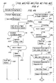
- 4A - 4D show a logic flow chart for operation of the controller of Fig. 3.
- Fig. 5
- is a logic flow chart showing shut-down procedure for the vehicle of Fig. 1.
- Referring now to Fig. 1, therein is shown a
utility vehicle 10 such as a riding mower or other grounds care machine having a tool-carryingframe 12 supported by right and left rear drivenwheels steerable wheels tool 24, shown in Fig. 1 as a mower deck , is supported from the underside of theframe 12 and includes a plurality of driven blade members 26 (Fig. 3) powered by electric motor structure 26'. The electric motor structure 26' may include a permanent magnet dc motors 26' individually driving each of theblade members 26 or other suitable drive arrangement including but not limited to a single motor driving theblade members 26 through a belt drive. The motors 26' can be "pancake" type motors to for more clearance on the top of thedeck 24. - The
frame 12 includes arear frame portion 12r on each side of thevehicle 10 supporting right and left integratedwheel motor assemblies reduction gear structure 34g and 36g located substantially entirely outwardly of therear frame portion 12r and generally withinrims 38 of thewheels rear frame portion 12r and the compactwheel motor assemblies opening accommodation space 40 between the assemblies and below the top of therear frame portion 12r unencumbered with transmission or other wheel drive structure. Aseat 42 is supported from the top of therear frame portion 12 behind anoperator control area 46 and ahood area 48 which extends forwardly from the control area. Asteering control 50 is located in thearea 46. - An
internal combustion engine 60 centered behind thefront wheels hood area 48. A combination starter/alternator 66 is supported at the forward end of theengine 60 between thefront wheels engine 60 and to provide high rpm, high torque engine starting at a low noise level. In the embodiment shown for a conventional lawn and garden tractor, the engine provides about fifteen horsepower and the alternator puts out about thirteen kilowatts of power at full engine power from a three phase permanent magnet brushless generator. As a starter, the depicted starter/alternator provides combustion engine cranking torque of greater than 40 Nm. It is to be understood that other engine/generator combinations and power outputs could be used. - A rectifier/inverter 68 (Fig. 3) is connected to the alternator which operates to boost generator voltage above the back emf of the generator. Current is injected into an inductance to provide the voltage increase. An
output 70 is connected to abattery pack 74 and tobus 76 having a bus voltage above 36 volts and typically about 42 volts. By operating the generator at an output level below the voltage on thebus 76 good efficiency over a wide range of engine speeds is achieved without need for a complicated voltage management scheme. With a back emf lower than the bus voltage, the electronics are designed to boost the generator output up to the bus voltage. When generating, controller transistors in the rectifier/inverter 68 are commutated 180 degrees out of phase from motoring. The inductance of the machine thus adds the supply voltage to the back emf voltage which raises the output over the bus voltage for charging the batteries. The necessary bus voltage can be generated efficiently over a wide range of engine speeds which allows running the engine at low speed for quiet operation when full power is not needed. Thebus 76 is connected to aninverter 80 with an 110 volt or 240 volt outlet 82 which can be conveniently located adjacent theaccommodation space 40 near the rear of thevehicle 10 for powering hand tools, providing emergency power to a building, and the like. Thebattery pack 74 can be of thin film absorbed glass mat or other compact construction which can be located adjacent theseat 42 near theinverter 80. - The
front wheels wheel 18 is shown approaching the left-most turn position. Thewheels transverse axle member 90 for pivoting about upright axes (see 18a in Fig. 2), and asteering linkage 92 generally of the type shown and described in commonly assigned U.S. Patent No. 6,456,925 provides positive steering of the wheels through a rack andpinion structure 96. In one embodiment (Fig. 1), anelectric motor 100 powers the rack andpinion structure 96 and provides a drive by wire function which is independent of a mechanical linkage connecting a steering wheel directly to thesteering linkage 92. Alternatively, a conventional mechanical steering linkage (not shown) can be provided between a steering wheel and thesteering linkage 92 as described in the aforementioned Patent No. 6,456,925 with themotor 100 acting as a power steering assist if desired. Another type of drive by wire steering control is shown in Fig. 3 wherein, rather than using a single motor, separate electrically operatedsteering motors wheels wheels wheel motor assemblies - The compact arrangement of the
wheel motor assemblies large accommodation space 40 facilitates mounting of a rearmaterial discharge chute 140 under the area of theseat 42 and generally under theframe 12. Thechute 140 is connected to the rear central portion of themower deck 24. Since the drive structure for thewheels accommodation space 40, the chute can have a more direct route rearwardly and chute size can be greater than with convention transmission systems. A cut material hopper 144 is shown connected to therear frame portion 12r, and thechute 140 opens into the upper front portion of the hopper 144. Therear discharge deck 24 facilitates close trimming on both sides of thevehicle 10. In addition, the construction permits transverse movement of thedeck 24 for further trimming enhancement and more top deck clearance for improved tool lift. Electric actuators indicated generally at 150 in Fig. 1 provide implement and tool lift and tool offset functions. - Referring now to Fig. 3, therein is shown an
electronic vehicle controller 160 having a steeringinput 162 from thesteering control 50, a speed command and direction input 164 from a foot pedal, and abrake command input 166 from a brake pedal. The pedals andsteering control 50 are located at thecontrol area 46 and are shown to include variable resistors providing an analog voltage signal to thecontroller 160 dependent on the selected position of each operator control. Thecontroller 160 also receives start and run signals from akey switch assembly 168 and engine speed and operating condition information vialines 170. - The
vehicle controller 160 calculates the differential speeds of the right and leftwheels wheels controller 160 then outputs a steering signal vialines steering motors vehicle 10 is so equipped (or to a single steering motor if the steered wheels are mechanically linked for steering), to control the positions of the steeredwheels Feedback lines 178 and 180 (or a single line if a single steering motor is used) provide feedback signals to thecontroller 160 utilized primarily to verify that the steeredwheels steerable wheels controller 160 provides speed control to the wheel drives depending on the steering input at 162 and the foot pedal speed input at 164. The right and left wheel motors 34' and 36' are connected tomotor controllers controller 160 dependent also on the steering input at 162 and the foot pedal speed input at 164. Speed and current feedback signals from the right and left wheel motors 34' and 36' are also inputted to the motor controllers at 194 and 196. The current feedback is added to the basic control at 184 and 186 and enables vector control if desired to enhance the control functions. - The steering and drive arrangement provides full time steerable differential drive wherein both rear wheels provide drive at all times for good traction characteristics. The vehicle turns well since the wheels are rotated at speeds matched to the requested turn angle. This control of the individual wheel speed is accomplished without need for a complicated and bulky spin steer transmission. When utilized with a 180 degree or other short radius steering linkage, a high degree of vehicle maneuverability is achieved. The
controller 160 utilizes the steering input signal at 162 and the desired ground speed input at 164 from the foot pedals to compute the correct wheel speed for the rear drive motors 34' and 36'. Further details of a control system for controlling the driven wheels may be had by reference to the aforementioned U.S. Patent 6,456,925. - The deck motors 26' (Fig. 3) are controlled with a
deck control switch 206 connected to thecontroller 160. Thecontroller 160 directs power from thebus 76 to the motors 26' when theswitch 206 is closed. Aninverter switch 208 connected to thecontroller 160, when closed, turns on theinverter 80 so that power can be supplied through the outlet 82. Thecontroller 160 filters operator speed requests at 164 utilizing a torque control map stored in controller memory. A control algorithm executed by the controller avoids engine overload and engine stoppage by causing electrical load to be taken from thebattery pack 74 as necessary and gradually applying generator load to allow a governor on the engine to match engine droop. If theengine 60 stops for any reason, thecontroller 160 initiates a shut-down routine (300 of Fig. 5). Upon indication at 301 of stoppage, right and left drive speed and torque are set to zero (302 and 303, respectively), and 120 ms delay is initiated at 304. Thereafter, the ignition relay is set to off and the control state is returned to initialization. - Referring to Figs. 4A - 4D, a logic flow chart is shown for the operation of the
controller 160. On turn-on of thevehicle 10, inputs are sampled at 400 to determine if there are any problems in the system or if a previous error state has not been corrected, and if so (401), the state is returned to Error at 402, an error message is provided at 403, and shutdown procedure is begun at 404. - Upon indication at 401 that no problems are detected, the state of the system is checked at 410. If the vehicle is in the initiation state, such as occurs at with normal start-up procedures, drive speeds are set to zero at 411 and interlock conditions such as brake on, speed control in neutral and mower deck off are checked at 412. If all the pre-established conditions are met, the ignition relay is turned on at 413 and the state of the
key switch 168 is polled at 414. If the switch is in the start position, engine cranking is begun (415). If the switch is not in the start position, the alternator is disengaged at 416. If cranking is indicated at 410, key position is checked at 420, and if starting is indicated, the interlock conditions are checked at 421. If conditions are as prescribed, the starter is turned on at 422, a generator speed is entered at 423. If the generator speed is sufficient for providing proper voltage to thebus 76, the generator is activated at 425 and the run timer is begun at 426. State is set to running at 427. - If the key is not in the start position at 420, the starter is turned off at 430, and a two-second time out is established at 431. Generator speed is checked after two second at 432, and, if sufficient, power generation is begun at 433 and the state is set to running at 434 prior to the next pass through the routine. If at 421 it is determined that not all of the interlock conditions are met, the starter is turned off at 440, a short time-out delay is established at 441 after which the shutdown procedure is begun at 442. If generator speed has not reached an acceptable level at 432 and generator speed is indicated to be below a minimum speed at 451, the shutdown procedure is begun at 452.
- Once the state at 410 is determined to be run, the drive to the
wheel motor assemblies deck switch 206 is polled at 463. If the deck is on and the deck flag is clear at 464, and if the foot pedal is in the neutral condition at 465, the deck is engaged at 466. If an override condition exists, such as mow in reverse switch has been activated (467), the deck override flag is set to true at 468. Otherwise, the deck override flag is cleared at 469. If the foot pedal is not in neutral at 465 and if the foot pedal is in reverse at 470, the deck override flag is checked (471). If the deck override flag has previously been set to true at 468 indicating a proper override condition exists, the deck engagement is enabled at 472. Otherwise, the deck is disengaged at 474 and the deck error flag is set at 475. If the foot pedal is not in reverse (470), the deck override flag is set to false at 480 and the deck is engaged at 481. - If at 461 it is determined that seat switch is off and at 483 (Fig. 4C) the vehicle brake is not engaged, shutdown is initiated at 484. If the seat switch is off (461) and the brake is on (483) the deck switch is polled at 485 and, if off, the deck is disengaged (486) and the deck error flag is set at 487. If the seat switch is on at 461 and the deck off indication is received at 463, the error deck flag is checked at 488 and deck override flag is checked at 489 before disengaging the deck at 490. The
steering algorithm 494 continues after condition checks. - Having described the preferred embodiment, it will become apparent that various modifications can be made without departing from the scope of the invention as defined in the accompanying claims.
Claims (14)
- A hybrid utility vehicle (10) including a frame (12) for supporting one or more tools (24), a combustion engine (60) supported on the frame (12), an electrical power source driven by the engine (60), right and left driven wheels (14, 16), steerable wheels (18, 20) offset from the driven wheels (14, 16), the driven wheels (14, 16) and steerable wheels (18, 20) supporting the frame (12) for steered movement over the ground, a preferably electric wheel motor structure (34, 36) connected to the driven wheels (14, 16), an electrically actuated steering structure (92) connected to the steerable wheels (18, 20) for moving the steerable wheel structure preferably approximately 180 degrees over a range of steered positions from a zero radius left turn position to a zero radius right turn position, an electronic controller (160) connected to the wheel motor structure (34, 36) and to the steering structure, a steering control (50) connected to the electronic controller (160) and providing a steering input control signal to the controller (160), the controller (160) responsive to the steering input control signal to operate the steering structure and control the relative speeds of the driven wheels (18, 20) for increased wheel traction and vehicle maneuverability and for decreased ground disturbance at the left and right zero radius turn steered positions.
- The utility vehicle according to claim 1, characterized in that the supported tool (24) comprises a mower deck supported between the driven wheels (14, 16), preferably comprising rear wheels, and steerable wheels (18, 20), the mower deck including a discharge chute (140), preferably a rear discharge chute, extending outwardly from the frame (12) between the left and the right driven wheels (14, 16), wherein preferably the chute location is below the frame (12) adjacent the wheel motor structure (34, 36).
- The utility vehicle according to claim 1 or 2, characterized in that the wheel motor structure (36) comprises right and left drive motors (34', 36') connected to the right and left driven wheels (14, 16), and wherein the discharge chute (140) extends under the frame (12) between the right and left drive motors (34', 36').
- The utility vehicle according to one or several of the previous claims, characterized in that the supported tool (24) comprises a mower deck, wherein the mower deck (24) includes at least one blade (26) driven by an electric blade motor (26') preferably connected to the power source, wherein the blade motor (26') preferably is connected to the electronic controller (160).
- The utility vehicle according to one or several of the previous claims, characterized by an electric actuator structure (150) connected to the tool (24) for moving the tool (24) relative to the frame (12), wherein the electric actuator structure (150) is located between the drive wheels (14, 16) above the discharge chute (140).
- The utility vehicle according to one or several of the previous claims, characterized in that the electrical power source comprises an electrical power generator, wherein the generator also is operable as a starter (66) for the combustion engine (60).
- The utility vehicle according to claim 6, characterized in that the generator and wheel motor structure (34, 36) are operable as a vehicle brake.
- The utility vehicle according to claim 6 or 7, characterized in that the generator is connected to an inverter (80) providing an output voltage in a range of about 110 to 240 volts for powering an accessory, and further comprising a control connection between the electronic controller (160) and the inverter (80) and/or wherein the generator drives the combustion engine (60) at a speed greater than 600 rpm preferably of approximately 1000 rpm on engine start-up and/or wherein the generator has an output of greater than 10 kW and provides a torque of greater than 40 Nm for engine cranking
- The utility vehicle according to one or several of the claims 6 to 8, characterized in that the generator is connected to a bus (76) having a bus voltage, wherein the back emf of the alternator is less than the bus voltage, and further comprising a voltage booster providing increased voltage to the bus.
- The utility vehicle according to one or several of the previous claims, characterized in that the one or more supported tools includes a selectively attachable cutting tool (24) adapted for support between the steerable wheels (18, 20) and the driven wheels (14, 16), the cutting tool having a discharge chute (140) adapted for support in a chute location between the driven wheels (14, 16), and wherein the inverter (80) is located above the chute location.
- The utility vehicle according to one or several of the previous claims, characterized by an operator speed control (164) connected to the electronic controller (160), and wherein the control of the speeds of the driven wheels (14, 16) during vehicle turns is responsive to the operator speed control (164), wherein preferably the driven wheels (14, 16) comprise rear wheels (14, 16) and the steerable wheel structure comprises non-driven wheels (18, 20) located forwardly of the rear wheels (14, 16).
- The utility vehicle according to one or several of the previous claims, characterized by a feedback structure (178, 180) connected between the steerable wheels (18, 20) and the electronic controller (160) and providing a steerable wheel position indication to the controller (160), wherein preferably the feedback structure (178, 180) provides an initial position signal to the electronic controller (160) at start up, the electronic controller (160) responsive to the initial position signal to determine if the steerable wheels (18, 20) are in a desired position.
- The utility vehicle according to one or several of the previous claims, characterized in that the preferably electrically operated steering structure is selectively removable from the steerable wheels (18, 20) to convert the steerable wheels (18, 20) to non-steered caster wheels.
- The utility vehicle according to one or several of the previous claims, characterized in that the electrically operated steering structure comprises an electric steering assist motor and/or that the electrically operated steering structure comprises a steer by wire structure.
Applications Claiming Priority (2)
| Application Number | Priority Date | Filing Date | Title |
|---|---|---|---|
| US732634 | 2003-12-10 | ||
| US10/732,634 US7017327B2 (en) | 2003-12-10 | 2003-12-10 | Hybrid electric tool carrier |
Publications (3)
| Publication Number | Publication Date |
|---|---|
| EP1541446A2 true EP1541446A2 (en) | 2005-06-15 |
| EP1541446A3 EP1541446A3 (en) | 2005-09-21 |
| EP1541446B1 EP1541446B1 (en) | 2008-01-16 |
Family
ID=34523051
Family Applications (1)
| Application Number | Title | Priority Date | Filing Date |
|---|---|---|---|
| EP04106288A Expired - Fee Related EP1541446B1 (en) | 2003-12-10 | 2004-12-03 | Utility vehicle |
Country Status (3)
| Country | Link |
|---|---|
| US (4) | US7017327B2 (en) |
| EP (1) | EP1541446B1 (en) |
| DE (1) | DE602004011313T2 (en) |
Cited By (7)
| Publication number | Priority date | Publication date | Assignee | Title |
|---|---|---|---|---|
| EP1943894A3 (en) * | 2007-01-15 | 2008-10-01 | Kanzaki Kokyukoki Mfg. Co., Ltd. | Riding lawn mower |
| EP2082916A1 (en) * | 2008-01-28 | 2009-07-29 | Textron Inc. | Dynamic tactical steering feedback |
| EP2082918A1 (en) * | 2008-01-28 | 2009-07-29 | Textron Inc. | Turf maintenance vehicle all-wheel drive system |
| CN101559727A (en) * | 2008-04-18 | 2009-10-21 | 株式会社神崎高级工机制作所 | Electric ground working vehicle |
| CN102700611A (en) * | 2012-05-25 | 2012-10-03 | 北京理工大学 | Steering system with coupling of electric drive tracked vehicle steering motor and unilateral drive motor |
| EP3977841A4 (en) * | 2019-07-09 | 2022-08-10 | Nanjing Chervon Industry Co., Ltd. | Riding lawn mower and control method therefor |
| EP4342709A1 (en) * | 2022-09-21 | 2024-03-27 | Iseki & Co., Ltd. | Work vehicle |
Families Citing this family (78)
| Publication number | Priority date | Publication date | Assignee | Title |
|---|---|---|---|---|
| US20060191261A1 (en) * | 2003-07-08 | 2006-08-31 | Bailey Rudolph V Sr | Gasoline to pneumatic engine conversion zero emission & fuel cost |
| US7017327B2 (en) * | 2003-12-10 | 2006-03-28 | Deere & Company | Hybrid electric tool carrier |
| DE102004007837A1 (en) * | 2004-02-17 | 2005-09-01 | Claas Selbstfahrende Erntemaschinen Gmbh | Agricultural working machine |
| US20060175098A1 (en) * | 2005-02-07 | 2006-08-10 | Bailey Sutherland | Activatable forward wheel steering mechanism for a zero turn lawnmower |
| EP2426033B1 (en) | 2005-07-22 | 2018-03-07 | MTD Products Inc | Steering systems, steering and speed coordination systems, and associated vehicles |
| GB0517200D0 (en) * | 2005-08-22 | 2005-09-28 | Torotrak Dev Ltd | Driving and steering of motor vehicles |
| GB0517201D0 (en) | 2005-08-22 | 2005-09-28 | Torotrak Dev Ltd | Driving and steering of motor vehicles |
| JP4812409B2 (en) * | 2005-11-16 | 2011-11-09 | 日立オートモティブシステムズ株式会社 | Power steering device |
| US8950520B2 (en) | 2006-07-07 | 2015-02-10 | Hydro-Gear Limited Partnership | Front steering module for a zero turn radius vehicle |
| US8844658B2 (en) * | 2006-07-07 | 2014-09-30 | Hydro-Gear Limited Partnership | Electronic steering apparatus |
| GB0615241D0 (en) | 2006-08-01 | 2006-09-06 | Bosch Gmbh Robert | Lawn-care apparatus |
| US7479754B2 (en) * | 2006-10-17 | 2009-01-20 | Desa Ip Llc | Hybrid electric lawnmower |
| US8732896B2 (en) | 2006-10-17 | 2014-05-27 | Mtd Products Inc | Hybrid electric cleaning device |
| WO2008048618A2 (en) | 2006-10-17 | 2008-04-24 | Desa Ip. Llc | Hybrid electric device |
| US7914022B2 (en) * | 2006-10-17 | 2011-03-29 | Mtd Products Inc | Vehicle control systems and methods |
| US20080120955A1 (en) * | 2006-10-17 | 2008-05-29 | Lucas Delbert R | Hybrid electric lawnmower |
| US7728534B2 (en) * | 2006-10-17 | 2010-06-01 | Mtd Products Inc | Hybrid electric lawnmower |
| US20080206026A1 (en) * | 2007-02-27 | 2008-08-28 | Jones Robert L | Tool carrier |
| EP1985487B1 (en) | 2007-04-24 | 2018-08-08 | Kanzaki Kokyukoki Mfg. Co., Ltd. | Riding lawn mower |
| US8076873B1 (en) | 2007-06-01 | 2011-12-13 | Mtd Products Inc | Hybrid outdoor power equipment |
| US7648002B2 (en) * | 2007-06-08 | 2010-01-19 | Deere & Company | Vehicle with coordinated Ackerman and differential steering |
| EP2197702B1 (en) | 2007-09-11 | 2011-11-30 | Hydro-Gear Limited Partnership | Electric drive vehicle control system |
| US8207693B2 (en) | 2007-09-11 | 2012-06-26 | Hydro-Gear Limited Partnership | Controller assemblies for electric drive utility vehicles |
| US7904217B2 (en) * | 2008-03-25 | 2011-03-08 | International Truck Intellectual Property Company, Llc | Battery pack management strategy in a hybrid electric motor vehicle |
| US8136613B2 (en) * | 2008-03-26 | 2012-03-20 | Mtd Products Inc | Vehicle control systems and methods |
| JP2009274651A (en) * | 2008-05-16 | 2009-11-26 | Toyota Industries Corp | Hybrid industrial vehicle |
| US8134244B2 (en) * | 2008-05-16 | 2012-03-13 | James Wurth | Hybrid start/run apparatus |
| WO2010048561A2 (en) | 2008-10-23 | 2010-04-29 | Hydro-Gear Limited Partnership | Control systems and methods for electric motors of utility vehicles |
| US9511659B2 (en) * | 2009-01-28 | 2016-12-06 | Steven Young | Method and apparatus for lawn care |
| US8640799B2 (en) | 2009-06-11 | 2014-02-04 | Illinois Tool Works Inc. | Welding systems powered by hybrid vehicles |
| US20110061355A1 (en) * | 2009-09-16 | 2011-03-17 | Griffin Randall J | Grass mowing machine with engine speed and voltage limiter |
| JP5463463B2 (en) * | 2009-11-30 | 2014-04-09 | 株式会社 神崎高級工機製作所 | Ride type ground work vehicle |
| JP5531211B2 (en) * | 2010-04-08 | 2014-06-25 | 株式会社 神崎高級工機製作所 | Electric work vehicle |
| US8708074B1 (en) | 2010-06-15 | 2014-04-29 | Hydro-Gear Limited Partnership | Selectable four-wheel drive system |
| US9073539B1 (en) | 2010-06-22 | 2015-07-07 | Hydro-Gear Limited Partnership | Auxiliary battery powered brake release assembly |
| US8543295B2 (en) * | 2010-11-30 | 2013-09-24 | Christian Stanton Carver Bryant | Electronically controlled speed limiting system for turf care machine |
| US8922049B2 (en) | 2010-12-02 | 2014-12-30 | Hydrive Vehicles, Incorporated | System for extracting electrical power from an electric vehicle |
| US20120217074A1 (en) * | 2011-02-28 | 2012-08-30 | Rudinec Stephen A | All-Electric Powered Vehicle |
| EP2731413B1 (en) | 2011-07-14 | 2017-10-04 | Husqvarna AB | Battery powered lawn care vehicle with drive efficiency indicator |
| US8740229B2 (en) * | 2011-07-26 | 2014-06-03 | William D. Ellsworth | Slope traversing system for zero turning radius vehicles |
| US10780918B2 (en) | 2011-09-22 | 2020-09-22 | Mtd Products Inc | Vehicle control systems and methods and related vehicles |
| US9069617B2 (en) | 2011-09-27 | 2015-06-30 | Oracle International Corporation | System and method for intelligent GUI navigation and property sheets in a traffic director environment |
| US8863485B2 (en) | 2012-01-05 | 2014-10-21 | Briggs & Stratton Corporation | Hybrid lawn mower drive system |
| EP2639128B1 (en) | 2012-03-13 | 2023-09-06 | Kanzaki Kokyukoki Mfg. Co., Ltd. | Work vehicle |
| US8983691B2 (en) * | 2012-08-07 | 2015-03-17 | Deere & Company | Electric lawn tractor roll away prevention system |
| DE102013013623B4 (en) | 2012-08-29 | 2022-06-30 | Kanzaki Kokyukoki Mfg. Co., Ltd. | Motor control system for an electric motor driven vehicle |
| JP2014073566A (en) * | 2012-10-05 | 2014-04-24 | Makita Corp | Power tool |
| US8800253B2 (en) * | 2012-10-25 | 2014-08-12 | Deere & Company | Control system for an implement with a rotary component |
| JP2013063092A (en) * | 2013-01-11 | 2013-04-11 | Kanzaki Kokyukoki Manufacturing Co Ltd | Vehicle with working machine |
| US10144083B2 (en) | 2013-02-22 | 2018-12-04 | Illinois Tool Works Inc. | Multi-operator engine driven welder system |
| HUE039546T2 (en) | 2013-03-15 | 2019-01-28 | Mtd Products Inc | Parking brake system for a lap bar controlled zero turn radius mower |
| JP6092006B2 (en) * | 2013-06-03 | 2017-03-08 | 株式会社クボタ | Mower |
| CN103350725B (en) * | 2013-07-23 | 2016-01-20 | 重庆润通科技有限公司 | Multi-functional riding type mower |
| US20150075880A1 (en) * | 2013-09-13 | 2015-03-19 | GK Machine, Inc. | Electric cart for facilitating the harvesting of berries and other crops |
| US9969258B1 (en) * | 2014-04-22 | 2018-05-15 | Hydro-Gear Limited Partnership | Transaxle for zero-turn vehicle |
| US9499199B1 (en) | 2014-04-23 | 2016-11-22 | Hydro-Gear Limited Partnership | Hybrid vehicle |
| US9278698B2 (en) * | 2014-04-23 | 2016-03-08 | Honda Motor Co., Ltd. | Methods and apparatus for limiting engine speed |
| US9725115B1 (en) | 2014-06-06 | 2017-08-08 | Hydro-Gear Limited Partnership | Zero turn radius vehicle with single steered wheel |
| CN104129284B (en) * | 2014-06-23 | 2017-01-18 | 北京理工大学 | Positive differential type electro-mechanical composite transmission device |
| CN107567411B (en) | 2015-01-26 | 2019-02-12 | Mtd产品公司 | Steering assembly for riding cropper |
| US10836426B1 (en) | 2015-04-06 | 2020-11-17 | Exmark Manufacturing Company, Incorporated | Active steering system and grounds maintenance vehicle including same |
| US10148202B2 (en) | 2015-10-16 | 2018-12-04 | Kohler Co. | Hybrid device with segmented waveform converter |
| US10063097B2 (en) | 2015-10-16 | 2018-08-28 | Kohler Co. | Segmented waveform converter on controlled field variable speed generator |
| US10778123B2 (en) | 2015-10-16 | 2020-09-15 | Kohler Co. | Synchronous inverter |
| US10148207B2 (en) | 2015-10-16 | 2018-12-04 | Kohler Co. | Segmented waveform converter on controlled field variable speed generator |
| JP6479627B2 (en) * | 2015-10-29 | 2019-03-06 | 株式会社クボタ | Electric work vehicle |
| JP2017163871A (en) * | 2016-03-15 | 2017-09-21 | 本田技研工業株式会社 | Lawn mower |
| JP2017163872A (en) * | 2016-03-15 | 2017-09-21 | 本田技研工業株式会社 | Lawn mower |
| JP6212591B2 (en) * | 2016-03-31 | 2017-10-11 | 本田技研工業株式会社 | Control device for autonomous vehicle |
| WO2019044291A1 (en) * | 2017-08-31 | 2019-03-07 | 本田技研工業株式会社 | Electric vehicle |
| CN209710730U (en) | 2017-12-28 | 2019-12-03 | 南京德朔实业有限公司 | Straddle riding type power-operated mower |
| US11173780B2 (en) * | 2018-01-04 | 2021-11-16 | Delta Systems, Inc. | Hybrid mower with electric blade control system |
| CN110313297B (en) * | 2018-03-28 | 2021-03-05 | 南京德朔实业有限公司 | Riding mower operating device and riding mower |
| EP3821692A4 (en) | 2018-09-27 | 2021-08-25 | Nanjing Chervon Industry Co., Ltd. | Lawnmower |
| CN110946001A (en) | 2018-09-27 | 2020-04-03 | 南京德朔实业有限公司 | Lawn mower and blade assembly suitable for lawn mower |
| US11148518B2 (en) * | 2018-12-26 | 2021-10-19 | Kubota Corporation | Electric work vehicle arrangement |
| USD995569S1 (en) | 2019-04-18 | 2023-08-15 | Nanjing Chervon Industry Co., Ltd. | Mower blade assembly |
| CN115520038A (en) | 2021-06-25 | 2022-12-27 | 南京泉峰科技有限公司 | Outdoor walking equipment |
Citations (3)
| Publication number | Priority date | Publication date | Assignee | Title |
|---|---|---|---|---|
| US6454032B1 (en) | 1999-03-26 | 2002-09-24 | Deere & Company | Lawn tractor vehicle |
| US6456925B1 (en) | 2000-09-11 | 2002-09-24 | Deere & Company | Vehicle driven wheel speed control system |
| US6631607B1 (en) | 1999-09-16 | 2003-10-14 | Mtd Products Inc | Zero turn tractor with front mounted engine |
Family Cites Families (30)
| Publication number | Priority date | Publication date | Assignee | Title |
|---|---|---|---|---|
| US3732671A (en) * | 1971-08-31 | 1973-05-15 | Deere & Co | Electric drive riding mower |
| US4335567A (en) * | 1980-09-02 | 1982-06-22 | The Toro Company | Bagging filament mower |
| US4395865A (en) * | 1981-01-28 | 1983-08-02 | Davis Jr Robert D | Self propelled lawn mower |
| US4415049A (en) | 1981-09-14 | 1983-11-15 | Instrument Components Co., Inc. | Electrically powered vehicle control |
| US4964265A (en) * | 1989-09-11 | 1990-10-23 | Young Carl W | Remotely controlled lawn mower |
| GB9310036D0 (en) | 1993-05-15 | 1993-06-30 | Solaria Ind Inc | Electrical powered small tractor |
| US5502957A (en) * | 1995-03-29 | 1996-04-02 | Robertson; Charles W. | Electric lawn mower with intelligent control |
| EP0755816A3 (en) * | 1995-07-28 | 1998-09-02 | Isuzu Ceramics Research Institute Co., Ltd. | Hybrid electric vehicle |
| US6082084A (en) * | 1995-11-13 | 2000-07-04 | Ransomes America Corporation | Electric riding mower with electric steering system |
| US6170242B1 (en) * | 1997-07-22 | 2001-01-09 | Ferris Industries, Inc. | Lawn mower having independent drive wheel suspension |
| US5913802A (en) * | 1997-06-06 | 1999-06-22 | Excel Industries, Inc. | Single lever drivewheel steering power lawn mower |
| JP3350413B2 (en) * | 1997-09-24 | 2002-11-25 | 株式会社クボタ | Mower |
| JP3418136B2 (en) * | 1999-03-17 | 2003-06-16 | 株式会社クボタ | Moore |
| US6571542B1 (en) * | 1999-03-25 | 2003-06-03 | Textron Inc. | Electric drive mower with interchangeable power sources |
| GB2348253B (en) | 1999-03-26 | 2003-04-02 | Rover Group | Transmission differential assembly with yaw control |
| AUPR047300A0 (en) * | 2000-10-03 | 2000-10-26 | Spark, Ian James | Improved off road vehicle |
| US6591593B1 (en) | 2000-10-23 | 2003-07-15 | Dennis Brandon | Electric riding lawn mower powered by an internal combustion engine and generator system |
| US6717281B1 (en) * | 2000-10-26 | 2004-04-06 | Dennis Brandon | Electric generator and motor drive system |
| US6604348B2 (en) * | 2001-02-06 | 2003-08-12 | Deere & Company | Mower with engine-driven blade and electrical propulsion |
| JP3827959B2 (en) * | 2001-02-13 | 2006-09-27 | 株式会社クボタ | Mower |
| DE10296661T5 (en) * | 2001-04-20 | 2004-08-05 | Seiko Epson Corp. | drive control |
| JP4223205B2 (en) * | 2001-08-27 | 2009-02-12 | 本田技研工業株式会社 | Driving force distribution device for hybrid vehicle |
| JP3970006B2 (en) * | 2001-12-07 | 2007-09-05 | 株式会社クボタ | Mower |
| US6848245B2 (en) * | 2002-03-06 | 2005-02-01 | Snapper, Inc. | Lawn mower with improved blade and blade housing |
| JP3683226B2 (en) * | 2002-03-27 | 2005-08-17 | 株式会社クボタ | Grass-cutting structure of grass mower |
| JP3776071B2 (en) * | 2002-09-26 | 2006-05-17 | 株式会社クボタ | Grass collecting device and mower equipped with the grass collecting device |
| US7027851B2 (en) * | 2002-10-30 | 2006-04-11 | Biosense Webster, Inc. | Multi-tip steerable catheter |
| JP2004328991A (en) * | 2003-04-09 | 2004-11-18 | Nissan Motor Co Ltd | Left and right wheel driving device for vehicle |
| WO2004099660A1 (en) * | 2003-05-09 | 2004-11-18 | Marugo Rubber Industries, Ltd. | Rubber hose and method for manufacture thereof |
| US7017327B2 (en) * | 2003-12-10 | 2006-03-28 | Deere & Company | Hybrid electric tool carrier |
-
2003
- 2003-12-10 US US10/732,634 patent/US7017327B2/en not_active Expired - Lifetime
-
2004
- 2004-12-03 EP EP04106288A patent/EP1541446B1/en not_active Expired - Fee Related
- 2004-12-03 DE DE602004011313T patent/DE602004011313T2/en active Active
-
2005
- 2005-11-14 US US11/273,141 patent/US20060090437A1/en not_active Abandoned
-
2008
- 2008-11-21 US US12/275,402 patent/US7721517B2/en not_active Expired - Lifetime
-
2010
- 2010-04-22 US US12/765,336 patent/US8056653B2/en not_active Expired - Lifetime
Patent Citations (3)
| Publication number | Priority date | Publication date | Assignee | Title |
|---|---|---|---|---|
| US6454032B1 (en) | 1999-03-26 | 2002-09-24 | Deere & Company | Lawn tractor vehicle |
| US6631607B1 (en) | 1999-09-16 | 2003-10-14 | Mtd Products Inc | Zero turn tractor with front mounted engine |
| US6456925B1 (en) | 2000-09-11 | 2002-09-24 | Deere & Company | Vehicle driven wheel speed control system |
Cited By (17)
| Publication number | Priority date | Publication date | Assignee | Title |
|---|---|---|---|---|
| US8544570B2 (en) | 2007-01-15 | 2013-10-01 | Kanzaki Kokyukoki Mfg. Co., Ltd. | Riding lawn mower |
| EP1943894A3 (en) * | 2007-01-15 | 2008-10-01 | Kanzaki Kokyukoki Mfg. Co., Ltd. | Riding lawn mower |
| US9420740B2 (en) | 2007-01-15 | 2016-08-23 | Kanzaki Kokyukoki Mfg. Co., Ltd. | Riding lawn mower |
| EP2186392A1 (en) * | 2007-01-15 | 2010-05-19 | Kanzaki Kokyukoki Mfg. Co., Ltd. | Riding lawn mower |
| US8657041B2 (en) | 2007-01-15 | 2014-02-25 | Kanzaki Kokyukoki Mfg. Co., Ltd. | Control system for a lawnmower vehicle having a plurality of electric motors |
| EP2082916A1 (en) * | 2008-01-28 | 2009-07-29 | Textron Inc. | Dynamic tactical steering feedback |
| EP2082918A1 (en) * | 2008-01-28 | 2009-07-29 | Textron Inc. | Turf maintenance vehicle all-wheel drive system |
| JP2009173279A (en) * | 2008-01-28 | 2009-08-06 | Textron Inc | Dynamic tactical steering feedback |
| US7894957B2 (en) | 2008-01-28 | 2011-02-22 | Textron Innovations Inc. | Dynamic tactical steering feedback |
| CN101559727A (en) * | 2008-04-18 | 2009-10-21 | 株式会社神崎高级工机制作所 | Electric ground working vehicle |
| CN101559727B (en) * | 2008-04-18 | 2014-01-22 | 株式会社神崎高级工机制作所 | Electric ground working vehicle |
| US7975786B2 (en) | 2008-04-18 | 2011-07-12 | Kanzaki Kokyukoki Mfg. Co., Ltd. | Electric ground working vehicle |
| EP2110295A3 (en) * | 2008-04-18 | 2010-04-14 | Kanzaki Kokyukoki Mfg. Co., Ltd. | Electric ground working vehicle |
| CN102700611A (en) * | 2012-05-25 | 2012-10-03 | 北京理工大学 | Steering system with coupling of electric drive tracked vehicle steering motor and unilateral drive motor |
| CN102700611B (en) * | 2012-05-25 | 2015-03-11 | 北京理工大学 | Steering system with coupling of electric drive tracked vehicle steering motor and unilateral drive motor |
| EP3977841A4 (en) * | 2019-07-09 | 2022-08-10 | Nanjing Chervon Industry Co., Ltd. | Riding lawn mower and control method therefor |
| EP4342709A1 (en) * | 2022-09-21 | 2024-03-27 | Iseki & Co., Ltd. | Work vehicle |
Also Published As
| Publication number | Publication date |
|---|---|
| EP1541446B1 (en) | 2008-01-16 |
| US20090288381A1 (en) | 2009-11-26 |
| US8056653B2 (en) | 2011-11-15 |
| DE602004011313D1 (en) | 2008-03-06 |
| US20100199622A1 (en) | 2010-08-12 |
| US7017327B2 (en) | 2006-03-28 |
| DE602004011313T2 (en) | 2009-01-02 |
| EP1541446A3 (en) | 2005-09-21 |
| US20050126145A1 (en) | 2005-06-16 |
| US20060090437A1 (en) | 2006-05-04 |
| US7721517B2 (en) | 2010-05-25 |
Similar Documents
| Publication | Publication Date | Title |
|---|---|---|
| EP1541446B1 (en) | Utility vehicle | |
| US8544570B2 (en) | Riding lawn mower | |
| US20160029555A1 (en) | Control sysytem for motor-driven lawnmower vehicle | |
| EP2082641B1 (en) | Turf maintenance vehicle with electrical demand sensor and method of operation | |
| US6857253B2 (en) | Electric riding mower with motor generator set and noise abatement | |
| JP2006507789A (en) | Hybrid power unit | |
| US20020104300A1 (en) | Mower with engine-driven blade and electrical propulsion | |
| US20080234096A1 (en) | Hybrid Utility Vehicle | |
| WO1997028681A9 (en) | Electric drive riding mower | |
| WO1997028681A2 (en) | Electric drive riding mower | |
| US11910745B2 (en) | Mower deck with actuated blade housings | |
| JP2013188161A (en) | Lawn mowing vehicle | |
| WO2023210087A1 (en) | Electric work vehicle | |
| WO2024050679A1 (en) | Mowing deck assembly and outdoor power machine with mowing deck assembly | |
| WO2024050704A1 (en) | Mowing deck assembly with onboard controller and outdoor power machine with mowing deck assembly | |
| JP2023152732A (en) | electric work vehicle | |
| AU705432C (en) | Electric drive riding mower | |
| JP2023163666A (en) | Electric working vehicle | |
| JP2023163667A (en) | Electric working vehicle | |
| WO2024081440A1 (en) | Systems and methods foran electric chore motor withan integrated motor controller |
Legal Events
| Date | Code | Title | Description |
|---|---|---|---|
| PUAI | Public reference made under article 153(3) epc to a published international application that has entered the european phase |
Free format text: ORIGINAL CODE: 0009012 |
|
| AK | Designated contracting states |
Kind code of ref document: A2 Designated state(s): AT BE BG CH CY CZ DE DK EE ES FI FR GB GR HU IE IS IT LI LT LU MC NL PL PT RO SE SI SK TR |
|
| AX | Request for extension of the european patent |
Extension state: AL BA HR LV MK YU |
|
| PUAL | Search report despatched |
Free format text: ORIGINAL CODE: 0009013 |
|
| AK | Designated contracting states |
Kind code of ref document: A3 Designated state(s): AT BE BG CH CY CZ DE DK EE ES FI FR GB GR HU IE IS IT LI LT LU MC NL PL PT RO SE SI SK TR |
|
| AX | Request for extension of the european patent |
Extension state: AL BA HR LV MK YU |
|
| 17P | Request for examination filed |
Effective date: 20060321 |
|
| AKX | Designation fees paid |
Designated state(s): DE GB |
|
| 17Q | First examination report despatched |
Effective date: 20060905 |
|
| GRAP | Despatch of communication of intention to grant a patent |
Free format text: ORIGINAL CODE: EPIDOSNIGR1 |
|
| GRAS | Grant fee paid |
Free format text: ORIGINAL CODE: EPIDOSNIGR3 |
|
| GRAA | (expected) grant |
Free format text: ORIGINAL CODE: 0009210 |
|
| AK | Designated contracting states |
Kind code of ref document: B1 Designated state(s): DE GB |
|
| REG | Reference to a national code |
Ref country code: GB Ref legal event code: FG4D |
|
| REF | Corresponds to: |
Ref document number: 602004011313 Country of ref document: DE Date of ref document: 20080306 Kind code of ref document: P |
|
| PLBE | No opposition filed within time limit |
Free format text: ORIGINAL CODE: 0009261 |
|
| STAA | Information on the status of an ep patent application or granted ep patent |
Free format text: STATUS: NO OPPOSITION FILED WITHIN TIME LIMIT |
|
| 26N | No opposition filed |
Effective date: 20081017 |
|
| PGFP | Annual fee paid to national office [announced via postgrant information from national office to epo] |
Ref country code: DE Payment date: 20171121 Year of fee payment: 14 |
|
| REG | Reference to a national code |
Ref country code: DE Ref legal event code: R119 Ref document number: 602004011313 Country of ref document: DE |
|
| PG25 | Lapsed in a contracting state [announced via postgrant information from national office to epo] |
Ref country code: DE Free format text: LAPSE BECAUSE OF NON-PAYMENT OF DUE FEES Effective date: 20190702 |
|
| PGFP | Annual fee paid to national office [announced via postgrant information from national office to epo] |
Ref country code: GB Payment date: 20200102 Year of fee payment: 16 |
|
| GBPC | Gb: european patent ceased through non-payment of renewal fee |
Effective date: 20201203 |
|
| PG25 | Lapsed in a contracting state [announced via postgrant information from national office to epo] |
Ref country code: GB Free format text: LAPSE BECAUSE OF NON-PAYMENT OF DUE FEES Effective date: 20201203 |