EP2082681A2 - Medical device - Google Patents
Medical device Download PDFInfo
- Publication number
- EP2082681A2 EP2082681A2 EP20090000510 EP09000510A EP2082681A2 EP 2082681 A2 EP2082681 A2 EP 2082681A2 EP 20090000510 EP20090000510 EP 20090000510 EP 09000510 A EP09000510 A EP 09000510A EP 2082681 A2 EP2082681 A2 EP 2082681A2
- Authority
- EP
- European Patent Office
- Prior art keywords
- wire
- housing
- camera
- fixing
- puncture needle
- Prior art date
- Legal status (The legal status is an assumption and is not a legal conclusion. Google has not performed a legal analysis and makes no representation as to the accuracy of the status listed.)
- Granted
Links
Images


Classifications
-
- A—HUMAN NECESSITIES
- A61—MEDICAL OR VETERINARY SCIENCE; HYGIENE
- A61B—DIAGNOSIS; SURGERY; IDENTIFICATION
- A61B1/00—Instruments for performing medical examinations of the interior of cavities or tubes of the body by visual or photographical inspection, e.g. endoscopes; Illuminating arrangements therefor
- A61B1/273—Instruments for performing medical examinations of the interior of cavities or tubes of the body by visual or photographical inspection, e.g. endoscopes; Illuminating arrangements therefor for the upper alimentary canal, e.g. oesophagoscopes, gastroscopes
-
- A—HUMAN NECESSITIES
- A61—MEDICAL OR VETERINARY SCIENCE; HYGIENE
- A61B—DIAGNOSIS; SURGERY; IDENTIFICATION
- A61B1/00—Instruments for performing medical examinations of the interior of cavities or tubes of the body by visual or photographical inspection, e.g. endoscopes; Illuminating arrangements therefor
- A61B1/04—Instruments for performing medical examinations of the interior of cavities or tubes of the body by visual or photographical inspection, e.g. endoscopes; Illuminating arrangements therefor combined with photographic or television appliances
- A61B1/041—Capsule endoscopes for imaging
-
- A—HUMAN NECESSITIES
- A61—MEDICAL OR VETERINARY SCIENCE; HYGIENE
- A61B—DIAGNOSIS; SURGERY; IDENTIFICATION
- A61B1/00—Instruments for performing medical examinations of the interior of cavities or tubes of the body by visual or photographical inspection, e.g. endoscopes; Illuminating arrangements therefor
- A61B1/313—Instruments for performing medical examinations of the interior of cavities or tubes of the body by visual or photographical inspection, e.g. endoscopes; Illuminating arrangements therefor for introducing through surgical openings, e.g. laparoscopes
- A61B1/3132—Instruments for performing medical examinations of the interior of cavities or tubes of the body by visual or photographical inspection, e.g. endoscopes; Illuminating arrangements therefor for introducing through surgical openings, e.g. laparoscopes for laparoscopy
-
- A—HUMAN NECESSITIES
- A61—MEDICAL OR VETERINARY SCIENCE; HYGIENE
- A61B—DIAGNOSIS; SURGERY; IDENTIFICATION
- A61B17/00—Surgical instruments, devices or methods, e.g. tourniquets
- A61B17/00234—Surgical instruments, devices or methods, e.g. tourniquets for minimally invasive surgery
- A61B2017/00238—Type of minimally invasive operation
- A61B2017/00283—Type of minimally invasive operation with a device releasably connected to an inner wall of the abdomen during surgery, e.g. an illumination source
-
- A—HUMAN NECESSITIES
- A61—MEDICAL OR VETERINARY SCIENCE; HYGIENE
- A61B—DIAGNOSIS; SURGERY; IDENTIFICATION
- A61B17/00—Surgical instruments, devices or methods, e.g. tourniquets
- A61B17/00234—Surgical instruments, devices or methods, e.g. tourniquets for minimally invasive surgery
- A61B2017/00349—Needle-like instruments having hook or barb-like gripping means, e.g. for grasping suture or tissue
Definitions
- the present invention relates to a medical device including a medical instrument fixed to an inner side of an abdominal cavity wall.
- an endoscope which is a medical instrument, includes an image pickup apparatus, and is introduced into a body cavity of a patient to perform various examinations and treatments of a diseased part within a body with an observation image shot by the image pickup apparatus.
- Such an endoscope includes an endoscope that is introduced into digestive organs such as esophagus, stomach, large intestine and duodenum, which are a luminal path within a body, from an anus or oral cavity, and an endoscope that is introduced into an abdominal cavity from the vicinity of a navel by puncturing and penetrating a body wall.
- the endoscope has a long insertion portion, which is inserted into a digestive path or an abdominal cavity.
- Japanese Patent Application Laid-Open Publication No. 2005-237979 discloses a capsule-type endoscope device technique which enables guiding to a target position through a tubular cavity while rotating upon reception of a rotating magnetic field from outside a body.
- capsule-type endoscope device described in Japanese Patent Application Laid-Open Publication No. 2005-237979 is an effective technique in a luminal path, it is difficult to use the conventional capsule-type endoscope device technique for endoscope observation in an abdominal cavity.
- an endoscope As a conventional method of introducing an endoscope into an abdominal cavity, a surgical operation in which a patient abdomen is punctured with a trocar for guiding an endoscope for observation into a body cavity and a trocar for guiding a treatment instrument to an area to be treated to provide a curative treatment by observing the treatment instrument and the area to be treated by the endoscope without largely opening the abdomen for the purpose of reducing invasion, namely, a laparoscopic surgery is performed, for example.
- an image pickup apparatus such as an endoscope for wide-angle observation in which a wide-angle visual field area is set such that an entire treated area in an abdominal cavity can be extensively observed in addition to the normal endoscope.
- the present invention has been made in view of the aforementioned problems, and it is an object of the present invention to provide a medical device including a medical instrument that can be fixedly installed within a body, capable of performing a minimally invasive surgical operation without increasing a burden on a patient. Furthermore, it is an object of the present invention to provide a medical device capable of stably maintaining a fixed state of a medical instrument such that the medical instrument does not wobble and shake throughout an operation.
- a medical device includes: a medical instrument introduced into a body cavity and having a contact portion that is fixed in contact with a wall within a body, and a wire; an extracorporeal device installed on a body surface and having a hole portion through which the wire can be inserted and removed, a fixing mechanism for fixing the wire inserted through the hole portion, and a housing that is fixed in contact with the body surface; and a pressure adjusting portion provided in one of the medical instrument and the extracorporeal device for maintaining a predetermined tensile force or more that is applied to the wire when the wire is fixed by the fixing mechanism with a body wall being sandwiched between the contact portion and the housing.
- Figs. 1 to 20 are related to a first embodiment of the present invention.
- Fig. 1 is a view illustrating a configuration of an endoscope system that is a medical device.
- Fig. 2 is a sectional view illustrating a configuration of an extracorporeal device.
- Fig. 3 is a top view illustrating an action of a hook needle of an extracorporeal device.
- Fig. 4 is a view illustrating a puncture rod of a forceps-type puncture needle that is a first modification.
- Fig. 5 is a view for explaining an operation of an opening and closing jaw of the forceps-type puncture needle in Fig.
- Fig. 6 is a view illustrating a puncture rod of a clip-type puncture needle that is a second modification.
- Fig. 7 is a view for explaining an operation of a claw portion of the clip-type puncture needle in Fig. 6 .
- Fig. 8 is a sectional view illustrating a configuration of a camera to be installed in an abdominal cavity.
- Fig. 9 is a view illustrating a state in which an abdominal wall of a patient is punctured with trocars.
- Fig. 10 is a view for explaining procedures for introducing a camera to be installed in an abdominal cavity into an abdominal cavity.
- Fig. 10 is a view for explaining procedures for introducing a camera to be installed in an abdominal cavity into an abdominal cavity.
- FIG. 11 is a view for explaining procedures for introducing a camera to be installed in an abdominal cavity into an abdominal cavity by illustrating a state in which an abdominal wall is punctured with a hook needle to hook a wire of the camera to be installed in an abdominal cavity.
- Fig. 12 is a view for explaining procedures for fixing a camera to be installed in an abdominal cavity to an abdominal wall by illustrating a state in which a hook needle, which hooks a wire of the camera to be installed in an abdominal cavity, is pulled up.
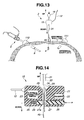
- Fig. 13 is a view for explaining procedures for fixing a camera to be installed in an abdominal cavity to an abdominal wall by illustrating a state in which a hook needle is pulled up and a fixing unit is lowered along the hook needle.
- Fig. 12 is a view for explaining procedures for fixing a camera to be installed in an abdominal cavity to an abdominal wall by illustrating a state in which a hook needle is pulled up and a fixing unit is lowered along the hook needle.
- Fig. 14 is a sectional view for explaining an action of an extracorporeal device.
- Fig. 15 is a view illustrating a state in which a fixing unit is installed on an abdomen and a camera to be installed in an abdominal cavity is fixed to an abdominal wall.
- Fig. 16 is a sectional view of the fixing unit and the camera to be installed in an abdominal cavity in the state shown in Fig. 15 .
- Fig. 17 is an entire configuration diagram of an endoscope system illustrating a state in which a camera to be installed in an abdominal cavity is fixed to an abdominal wall.
- Fig. 18 is a sectional view for explaining procedures for removing a fixing unit from a wire of a camera to be installed in an abdominal cavity.
- Fig. 15 is a view illustrating a state in which a fixing unit is installed on an abdomen and a camera to be installed in an abdominal cavity is fixed to an abdominal wall.
- Fig. 16 is a sectional view of the fixing unit and the camera to be installed in an abdominal cavity in the
- FIG. 19 is a view for explaining procedures for changing a position of a camera to be installed in an abdominal cavity by illustrating a state in which another position of an abdominal wall is punctured with a hook needle to hook a wire of the camera to be installed in an abdominal cavity.
- Fig. 20 is a view illustrating a state in which a fixing unit is installed on an abdomen and a camera to be installed in an abdominal cavity is fixed to an abdominal wall after changing the position.
- an endoscope system 1 of the present embodiment for performing a laparoscopic surgery is mainly constituted by a rigid endoscope 2 that is a first shooting apparatus, an extracorporeal device 3, a very small camera to be installed in an abdominal cavity (abbreviated to camera below) 4 that is a second shooting apparatus and an image pickup apparatus, a light source device 5, a camera control unit (abbreviated to CCU below) 6 that is a signal processing device in which an image processing circuit is incorporated, and a display device 7 that is connected to the CCU 6 via a communication cable 13 and displays an observation image.
- a rigid endoscope 2 that is a first shooting apparatus
- an extracorporeal device 3 a very small camera to be installed in an abdominal cavity (abbreviated to camera below) 4 that is a second shooting apparatus and an image pickup apparatus
- a light source device 5 a camera control unit (abbreviated to CCU below) 6 that is a signal processing device in which an image processing circuit is incorporated
- a display device 7 that is
- the light source device 5 supplies an illuminating light to an illuminating optical system provided in the rigid endoscope 2.
- the light source device 5 and the rigid endoscope 2 are removably connected by a light source cable 10.
- the rigid endoscope 2 is mainly constituted by a rigid insertion portion 8, and an operation portion 9 sequentially connected to a proximal end of the insertion portion 8.
- an image guide and a light guide bundle are inserted through its interior portion, and a shooting optical system for focusing a subject image onto a rigid endoscope camera described below via the image guide, and the illuminating optical system for emitting an illuminating light from the light guide bundle toward a subject are disposed on its distal end surface.
- An unillustrated camera head in which a solid-state image pickup device such as CCD and CMOS is disposed is incorporated in the operation portion 9 of the rigid endoscope 2.
- An optical image of an observed region illuminated by the illuminating light supplied from the light source device 5 to the rigid endoscope 2 through the light source cable 10 is picked up by the camera head in the operation portion 9 through the image guide in the insertion portion 8.
- the rigid endoscope camera photoelectrically converts the picked-up optical image into an image pickup signal, which is transmitted to the CCU 6 through an image pickup cable 11.
- an image pickup optical system is set such that its angle of view ⁇ in which images can be shot (see Fig. 17 ) is 70° to 75°, for example.
- the CCU 6 generates a video signal from the transmitted image signal, and outputs the video signal to the display device 7.
- the display device 7 is a liquid crystal display, for example.
- the display device 7 receives the video signal outputted from the CCU 6, and displays both a normal observation image by the rigid endoscope 2 and a wide-angle observation image by the camera 4 on one screen or switches the normal observation image and the wide-angle observation image to separately display the images on the screen.
- the CCU 6 is removably connected to a fixing unit 15 of the extracorporeal device 3 described below via an electric cable 12.
- the extracorporeal device 3 includes the fixing unit 15 for pulling and fixing the camera 4 in a body cavity, and a hook needle 16 that is a puncture needle for hooking and pulling up the camera 4 as shown in Figs. 2 and 3 .
- the fixing unit 15 has a receiver 22 and an electrical connector portion 23 electrically connected to the receiver 22, which are incorporated in a housing 21 formed of a nonmagnetic material.
- the electrical connector portion 23 is connected to the electric cable 12 that is connected to the CCU 6. Through the electric cable 12, the fixing unit 15 receives power from the CCU 6 and transmits a signal from the receiver 22 to the CCU 6.
- a slide hole portion 24 is formed in the housing 21 from a side surface in a lateral direction.
- a wire fixing lever 26, which constitutes a fixing portion formed of a nonmagnetic material, where an urging spring 25 is fixed to its end surface, is inserted and disposed in the slide hole portion 24.
- the wire fixing lever 26 has a substantially rectangular parallelepiped shape, and is slidably disposed along the slide hole portion 24 in an inward direction of the housing 21.
- a hole portion 27 having a convex-shaped arc surface 27a on the urging spring 25 side is formed in an intermediate portion of the wire fixing lever 26.
- a vertically penetrating wire insertion portion 28 is formed in the housing 21.
- a cone-shaped tapered surface 29 is formed so as to widen toward a top portion to be an opening on a top surface of the housing 21.
- the hook needle 16 is removably inserted and disposed in the vertically penetrating hole with the wire fixing lever 26 being pushed into a slide position in the housing 21 where the hole portion 27 of the wire fixing lever 26 and the wire insertion portion 28 correspond to each other.
- the hook needle 16 of the extracorporeal device 3 includes a cylindrical puncture needle tube 31, a needle head 32 sequentially provided in a top portion of the puncture needle tube 31, a puncture rod 33 in which a hook portion 34 slidably inserted into the puncture needle tube 31 is formed in a distal end, a hook head 35 sequentially provided in a top portion of the puncture rod 33, and a spring 36 interposed between the hook head 35 and the needle head 32.
- the puncture needle tube 31 is an about 3 mm (in diameter) elongated metal tube body whose distal end is formed to have a sharp needle shape cut off at a slant.
- the needle head 32 has a larger outer diameter than the puncture needle tube 31, and its distal end side is formed to have a cone shape and is integrally formed with the puncture needle tube 31.
- the needle head 32 is in abutment with the tapered surface 29 formed on the top portion of the housing 21, so that the hook needle 16 is configured not to fall off from the housing 21.
- the puncture rod 33 is an elongated metal stick body.
- the hook head 35 sequentially provided in the top portion is urged in a direction to be separated from the needle head 32 by the spring 36. Accordingly, the hook portion 34 formed in the distal end of the puncture rod 33 is housed in the puncture needle tube 31.
- the hook needle 16 when a user pushes the hook head 35 into the puncture needle tube 31 against an urging force of the spring 36 (arrow F in Fig. 3 ), the hook portion 34 formed in the distal end projects from the distal end of the puncture needle tube 31.
- the wire fixing lever 26 is inserted and fixed to the housing 21 due to a pressing force in an outward direction of the housing 21 caused by an urging force of the urging spring 25. That is, an outer periphery surface of the puncture needle tube 31 is pressed by the arc surface 27a formed in one side surface of the hole portion 27 of the wire fixing lever 26 and is in abutment with an inner surface of the wire insertion portion 28, so that the hook needle 16 is fixed in a state in which the hook needle 16 is inserted through the housing 21.
- the hook needle 16 of the extracorporeal device 3 may be configured as the forceps-type puncture needle shown in Figs. 4 and 5 , or the clip-type puncture needle shown in Figs. 6 and 7 .
- an operation wire 33a is inserted through the puncture rod 33, and an opening and closing jaw 37 can be opened and closed around a rotation axis 37a with respect to the puncture rod 33 by a pulling and loosening operation of the operation wire 33a.
- saw-tooth concavities and convexities 38 are formed on a side portion of the puncture rod 33, and the opening and closing jaw 37 is engaged with the concavities and convexities 38.
- a claw portion 39 is provided in the hook portion 34 of the puncture rod 33.
- the claw portion 39 is disposed adjacent to or in contact with a claw receiver 39a on the side of a distal end side portion of the puncture rod 33.
- the claw portion 39 has an elastic portion 39b that is deformed by a predetermined amount of force.
- the clip-type puncture needle can hook the wire 45 of the camera 4 such that the wire 45 is difficult to fall off from the hook portion 34.
- the camera 4 is mainly constituted by a camera body 41 and an abdominal wall fixing portion 42 that is a contact portion with a wall within a body, which are sequentially provided, as shown in Fig. 8 .
- the camera body 41 is a so-called capsule-type image pickup unit. Its outer shape is formed with a substantially dome-shaped transparent hood 51 on a distal end side (on a lower side in Fig. 8 ), and a camera housing 52 formed of a nonmagnetic material in which the transparent hood 51 is disposed so as to hermetically seal one surface.
- an objective lens group 54 held in a lens holding hole that is formed in substantially the center of the above surface, and a solid-state image pickup device unit 55 such as CCD and C-MOS in which a light receiving portion is disposed in a position where a shooting light is focused by the objective lens group 54 are provided.
- a transmitter 57 is disposed, and a battery 56 for feeding power to the transmitter 57, the white LEDs 53 and the solid-state image pickup device unit 55 is incorporated.
- an image pickup optical system that picks up an image in a wide-angle visual field area is set such that its angle of vision ⁇ in which images can be shot (see Fig. 17 ) is 90° or more, for example.
- An image signal photoelectrically converted by the solid-state image pickup device unit 55 is wirelessly transmitted from the transmitter 57 to the receiver 22 disposed in the housing 21 of the extracorporeal device 3.
- the abdominal wall fixing portion 42 is formed of a flexible elastic member such as silicone rubber, for example.
- the abdominal wall fixing portion 42 includes a connecting portion 61 fitted into a proximal end portion of the camera housing 52, and a suction cup 62, which is a pressure adjusting portion on the camera 4 side, in a top end portion that is a proximal end side of the connecting portion 61.
- a convex portion 63 that projects in a cylindrical shape in substantially the center of a surface of the suction cup 62, and a through hole 64 in the center of the connecting portion 61 so as to be in communication with a hole portion of the convex portion 63 are formed in the abdominal wall fixing portion 42.
- a hoisting wire 45 having a predetermined length is inserted through the through hole 64 of the abdominal wall fixing portion 42.
- a coupling portion 65 connected by caulking is provided in one end portion of the wire 45.
- the coupling portion 65 is fitted and fixed to the center of a proximal end surface of the camera housing 52. That is, the wire 45 is provided so as to extend from the center of the suction cup 62.
- the wire 45 may be a thread such as a surgical suture, or a stranded wire made of metal.
- the endoscope system 1 in the present embodiment having the configuration described above is used for a laparoscopic surgery, and is used for a treatment in an abdominal cavity that is one of body cavities of a patient.
- an operator makes two small dissections in an abdominal wall 102 of a patient 100 by using a surgical knife or the like, and punctures the dissections with trocars 110 and 111 as shown in Fig. 9 .
- the operator makes a puncture into an abdominal cavity 101 with the trocar 111 for introducing a treatment instrument 120 such as a grasping forceps into the abdominal cavity 101 by dissecting the abdominal wall 102 or the like in another position apart a predetermined distance from the trocar 110 for introducing the rigid endoscope 2 into the abdominal cavity 101.
- a treatment instrument 120 such as a grasping forceps into the abdominal cavity 101 by dissecting the abdominal wall 102 or the like in another position apart a predetermined distance from the trocar 110 for introducing the rigid endoscope 2 into the abdominal cavity 101.
- the operator inserts the puncture needle tube 31 of the hook needle 16 into the wire insertion portion 28 provided in the fixing unit 15 of the extracorporeal device 3 as shown in Fig. 10 .
- the operator pushes the wire fixing lever 26 into the housing 21 such that the puncture needle tube 31 penetrates the fixing unit 15, and inserts the puncture needle tube 31 such that the puncture needle tube 31 penetrates the hole portion 27 of the wire fixing lever 26.
- the operator allows the puncture needle tube 31 to sufficiently project from a bottom surface of the fixing unit 15 such that the fixing unit 15 is sufficiently located on the needle head 32 side that is a hand side of the puncture needle tube 31 (see Figs. 2 and 3 ).
- the arc surface 27a that is one wall surface of the hole portion 27 of the wire fixing lever 26 is in abutment with and holds the puncture needle tube 31 by the urging force of the urging spring 25 on the wire fixing lever 26, so that the fixing unit 15 does not fall off from the puncture needle tube 31.
- the operator inserts the insertion portion 8 of the rigid endoscope 2 into the abdominal cavity 101 through the trocar 110.
- the operator inserts the camera 4 grasped by the treatment instrument 120 such as a grasping forceps into the abdominal cavity 101 through the trocar 111.
- the operator may insert the camera 4 into the abdominal cavity 101 while checking an image by the rigid endoscope 2.
- the convex portion 63 (see Fig. 8 ) that projects in a cylindrical shape in substantially the center of the surface of the suction cup 62 is grasped by the treatment instrument such as a grasping forceps. Since the convex portion 63 is provided in substantially the center of the surface of the suction cup 62, the camera 4 can be easily grasped by the treatment instrument in a balanced manner. Accordingly, the operator can easily insert the camera 4 into the trocar 111 at the time of introducing the camera 4 into the abdominal cavity, that is, can easily introduce the camera 4 into the abdominal cavity 101 such that the camera 4 is not caught in the trocar 111.
- the operator punctures the abdominal wall 102 with the puncture needle tube 31 of the hook needle 16 which is being inserted and held in the fixing unit 15 that constitutes the extracorporeal device 3 such that the puncture needle tube 31 penetrates the abdominal wall 102 while checking the image by the rigid endoscope 2 as shown in Figs. 10 and 11 .
- the operator pushes the hook head 35 in a direction indicated by an arrow F in Fig. 11 . From the state, the operator hooks the wire 45 of the camera 4 into the hook portion 34 formed in the puncture rod 33 while watching the image by the rigid endoscope 2.
- the operator extracts the puncture needle tube 31 of the hook needle 16 from the abdominal cavity 101 to outside a body (UP direction in Fig. 12 ) with the wire 45 being hooked into the hook portion 34 of the puncture rod 33 as shown in Fig. 12 .
- the operator moves the fixing unit 15 relative to the puncture needle tube 31 in an abdomen direction of the patient 100 (DOWN direction in Fig. 13 ) while extracting the puncture needle tube 31 of the hook needle 16 from the abdominal cavity 101, and pulls the puncture needle tube 31 until the wire 45 passes through the wire insertion portion 28 of the fixing unit 15 as shown in Fig. 13 .
- the operator can easily slide the fixing unit 15 relative to the puncture needle tube 31 of the hook needle 16.
- the operator moves the fixing unit 15 relative to the wire 45 in the abdomen direction of the patient 100 (DOWN direction in Fig. 14 ) while pulling the wire 45 itself (UP direction in Fig. 14 ) as shown in Fig. 14 .
- the operator can easily slide the fixing unit 15 relative to the puncture needle tube 31 of the hook needle 16 and the wire 45 of the camera 4 by maintaining a state in which the wire fixing lever 26 of the fixing unit 15 is pushed into the housing 21.
- the operator pulls the wire 45 of the camera 4 until the abdominal wall 102 is sandwiched between the fixing unit 15 and the camera 4 in a state in which the fixing unit 15 is placed on the abdomen of the patient 100.
- the operator releases the pushing of the wire fixing lever 26 of the fixing unit 15 when confirming that the suction cup 62 of the camera 4 sticks to an inner surface of the abdominal wall 102 as shown in Fig. 16 from the image by the rigid endoscope 2.
- the wire fixing lever 26 of the fixing unit 15 is thereby moved in a direction of an arrow R in Fig. 16 upon reception of the urging force of the urging spring 25, so that the hole portion 27 is misaligned with the wire insertion portion 28 of the housing 21.
- the wire 45 inserted through the hole portion 27 and the wire insertion portion 28 is caught therein and is thereby fixed to the housing 21.
- a given tensile force or more is always applied to the wire 45 between the fixing lever 26 and the suction cup 62. Accordingly, the given tensile force or more applied to the wire 45 at all times is maintained, so that the fixing unit 15 and the camera 4 are fixed with the abdominal wall 102 being sandwiched therebetween.
- the camera 4 is thereby installed in a reliably stable state in the abdominal cavity 101 of the patient 100, and the laparoscopic surgery is performed by the endoscope system 1 of the present embodiment.
- One end portion of an unillustrated insufflation tube is attached to the trocar 110, for example, and a carbon dioxide gas or the like is injected into the abdominal cavity as an insufflation gas for the purpose of securing a visual field of the rigid endoscope 2 and a region in which an operation instrument or the like is operated, for example.
- the operator inserts the rigid endoscope 2 through the trocar 110 and the treatment instrument 120 through the trocar 111 to perform the laparoscopic surgery in a state in which the camera 4 sticks to the abdominal wall 102 to be placed in the abdominal cavity 101.
- the operator when the operator wants to change a fixed position of the camera 4 in the abdominal cavity 101 of the patient 100, the operator removes the fixing unit 15 from the wire 45 while pushing the wire fixing lever 26 of the fixing unit 15 into the housing 21 in a state in which the camera 4 is grasped by the treatment instrument 120 in the abdominal cavity 101 as shown in Fig. 18 . After that, the operator inserts and disposes the hook needle 16 in the wire insertion portion 28 of the fixing unit 15 as described above.
- the operator makes a small dissection in the abdominal wall 102 of the patient 100 in a desired position by using a surgical knife or the like, and reinserts the trocar 110 into the dissection.
- the operator introduces the rigid endoscope 2 into the abdominal cavity 101 through the reinserted trocar 110 as shown in Fig. 19 .
- the operator makes a puncture with the puncture needle tube 31 of the hook needle 16 inserted and disposed in the fixing unit 15 from outside the body into the abdominal cavity 101 in a position where the camera 4 is to be installed.
- the operator pushes the hook head 35 of the hook needle 16 to guide the puncture rod 33 from the puncture needle tube 31 and hook the wire 45 of the camera 4 into the hook portion 34 while checking the image by the rigid endoscope 2. Then, the operator removes the hook needle 16 from the fixing unit 15 as described above, and pulls the wire 45 inserted through the fixing unit 15 to fix the fixing unit 15 and the camera 4 such that the abdominal wall 102 is sandwiched between the fixing unit 15 and the camera 4 (see Fig. 20 ).
- the endoscope system 1 in the present embodiment can easily change a visual field direction of the camera 4 in the abdominal cavity 101 by imposing a burden on the patient as little as possible as described above. That is, it is preferable to perform the laparoscopic surgery by locating the camera 4 in a position where an organ in the abdominal cavity 101 extensively shot by the camera 4 can be easily diagnosed. The operator can easily change the fixed position of the camera 4 in the abdominal cavity 101.
- the operator when the laparoscopic surgery is completed, the operator removes the fixing unit 15 from the wire 45 while pushing the wire fixing lever 26 of the fixing unit 15 into the housing 21.
- the operator grasps the camera 4 in the abdominal cavity 101 by the treatment instrument 120 such as a grasping forceps, and removes the camera 4 from the abdominal cavity 101 to outside the body through the trocar 111.
- body tissue in a body cavity, the abdominal cavity 101 here can be observed from a plurality of viewpoints including a wide angle.
- an operation of a large organ can be performed, or an entire resection line at the time of resecting a large intestine can be easily recognized, for example.
- a minimally invasive surgical operation can be performed using the endoscope system 1 without increasing a burden on the patient.
- the treatment by the laparoscopic surgery becomes easy by using the endoscope system 1 of the present invention.
- Figs. 21 to 24 are related to the second embodiment of the present invention.
- Fig. 21 is a sectional view of an extracorporeal device.
- Fig. 22 is a sectional view of a fixing unit and a camera to be installed in an abdominal cavity for explaining procedures for fixing the fixing unit and the camera to be installed in an abdominal cavity to an abdominal wall.
- Fig. 23 is a sectional view of a fixing unit and a camera to be installed in an abdominal cavity being fixed to an abdominal wall.
- Fig. 24 is a sectional view of an extracorporeal device illustrating a modification.
- the same constituent elements as those in the endoscope system 1 of the first embodiment described above are assigned the same reference numerals to omit the detailed description thereof.
- the fixing unit 15 of the extracorporeal device 3 in the present embodiment includes a pressure detecting mechanism as a pressure adjusting portion on the extracorporeal device 3 side, in which the wire fixing lever 26 is moved to fix the wire 45 to the housing 21 when a predetermined pressure is applied to the housing 21 which is pressed by the abdominal wall 102.
- a lock body 77 including a claw portion 77a hooked on a step portion 74 of the wire fixing lever 26 at one end is rotatably disposed by a rotation axis 76 in the housing 21 of the extracorporeal device 3.
- one end is urged downward by a torsion spring 75 along the rotation axis 76 such that the claw portion 77a on the other end side is moved upward.
- a hollow skirt body 71 is disposed so as to be slidable in a vertical direction in a bottom portion of the housing 21.
- an inward-directed flange 7 1 b is formed in an opening of a top portion, and a hole portion 71a through which the hook needle 16 and the wire 45 are inserted is provided in a bottom portion.
- the inward-directed flange 71 b is in abutment with an outward-directed flange 21a formed in a bottom side portion of the housing 21, so that the skirt body 71 is disposed so as not to fall off from the housing 21.
- a spring 72 is provided inside the skirt body 71.
- the spring 72 urges the housing 21 and the skirt body 71 such that the housing 21 and the skirt body 71 are separated from each other in a vertical direction.
- a pin 73 which projects from a bottom surface of an interior portion to penetrate into the housing 21 and pushes up the lock body 77 upward along the rotation axis 76 against an urging force of the torsion spring 75, is disposed in the skirt body 71.
- the fixing unit 15 has a configuration in which the pin 73 pushes up the lock body 77 upward along the rotation axis 76 when the skirt body 71 is moved upward and the housing 21 is moved downward against an urging force of the spring 72.
- an operation button portion 26b is integrally formed in an end portion that projects outside the housing 21.
- the wire 45 is pulled out to outside of a body by the hook needle 16 and the pulled out wire 45 is allowed to pass through the wire insertion portion 28 and the hole portion 71a of the fixing unit 15 as shown in Fig. 22 in a similar manner to the first embodiment. Subsequently, the wire 45 is pulled (UP direction in Fig. 22 ), so that the fixing unit 15 of the extracorporeal device 3 is moved in an abdomen direction (DOWN direction in Fig. 22 ) of the patient 100.
- the wire 45 of the camera 4 is pulled until the abdominal wall 102 is sandwiched between the fixing unit 15 and the camera 4.
- the pin 73 pushes up the lock body 77 upward along the rotation axis 76 against the urging force of the torsion spring 75.
- the claw portion 77a is thereby unhooked from the step portion 74, so that the wire fixing lever 26 of the fixing unit 15 receives the urging force of the urging spring 25 to be moved in a direction of an arrow R in Fig. 23 .
- the hole portion 27 is thereby misaligned with the wire insertion portion 28 of the housing 21. Accordingly, the wire 45 inserted through the hole portion 27 and the wire insertion portion 28 is caught by the wire fixing lever 26 and is fixed to the housing 21.
- the fixing unit 15 and the camera 4 are thereby fixed with the abdominal wall 102 being sandwiched therebetween.
- the fixing unit 15 in the present embodiment has a configuration in which the wire fixing lever 26 is moved and the wire 45 is fixed when a predetermine pressure or more is applied in a direction where the housing 21 1 and the skirt body 71 approach each other against the spring 72 with the abdominal wall 102 being sandwiched between the fixing unit 15 and the camera 4.
- the skirt body 71 on the abdominal wall 102 receives a force in a direction to be separated from the housing 21 by the spring 72.
- a force in a direction to be separated from the abdominal wall 102 also acts on the suction cup 62 of the camera 4 due to its elastic force. Accordingly, a force in a direction where the housing 21 that fixes the wire 45 and the camera 4 are separated from each other is applied at all times, so that the fixing unit 15 and the camera 4 are reliably fixed with the abdominal wall 102 being sandwiched therebetween by maintaining a given tensile force or more at all times by a contact surface of the skirt body 71 and a suction surface of the suction cup 62 of the camera 4, which hold the abdominal wall 102.
- the endoscope system 1 of the present embodiment has a configuration in which the hook needle 16 and the wire 45 are easily inserted and removed and operability is improved since the lock body 77 is hooked when an operator pushes the wire fixing lever 26 of the fixing unit 15 into the housing 21 once and the state in which the wire fixing lever 26 is pushed into the housing 21 is maintained, in addition to the effects in the first embodiment.
- the pressure detecting mechanism as the pressure adjusting portion on the extracorporeal device 3 side may have a configuration in which the fixation of the wire fixing lever 26 is electrically released by a pressure sensor 83 as shown in Fig. 24 .
- a battery 81, a control circuit 82, the pressure sensor 83, a vertically slidable claw portion 86 having a solenoid mechanism by an electromagnet 84 and a permanent magnet 85, and a spring 87 for urging the permanent magnet 85 upward with the claw portion 86 are provided.
- a magnetic force generated by the electromagnet 84 and a magnetic force of the permanent magnet 85 toward the electromagnet 84 side are set to have the same pole. That is, the electromagnet 84 and the permanent magnet 85 are set to repel each other.
- the pressure sensor 83 is disposed on a bottom surface portion of the housing 21, and is electrically connected to the control circuit 82.
- the battery 81 supplies driving power to the control circuit 82 and the pressure sensor 83.
- the control circuit 82 is electrically connected to the electromagnet 84, and feeds power and stops feeding power to turn ON/OFF the electromagnet 84 based on a detection signal of the pressure sensor 83. Also, a predetermined contact pressure is set in the pressure sensor 83. When detecting a pressure larger than the predetermined contact pressure, the pressure sensor 83 outputs the detection signal to the control circuit 82.
- the control circuit 82 stops feeding power to the electromagnet 84. At this time, the permanent magnet 85 is moved upward with the claw portion 86 by an urging force of the spring 87.
- the claw portion 86 receiving the force moving upward is hooked on the step portion 74 of the wire fixing lever 26 when the wire fixing lever 26 is pushed into the housing 21. Accordingly, the state in which the wire fixing lever 26 is pushed into the housing 21 is maintained.
- the wire 45 is pulled out to outside of a body by the hook needle 16, and the pulled out wire 45 is allowed to pass through the wire insertion portion 28 and the hole portion 71 a of the fixing unit 15 in a similar manner to the above description. Subsequently, with the fixing unit 15 being placed on the abdomen of the patient 100, the wire 45 of the camera 4 is pulled until the abdominal wall 102 is sandwiched between the fixing unit 15 and the camera 4.
- the control circuit 82 feeds power to the electromagnet 84.
- the permanent magnet 85 thereby repels the electromagnet 84, and is moved downward with the claw portion 86 against the urging force of the spring 87.
- the claw portion 86 is thereby unhooked from the step portion 74 of the wire fixing lever 26, and the wire fixing lever 26 is moved in an outward direction from the housing 21 upon reception of the urging force of the urging spring 25. That is, the hole portion 27 of the wire fixing lever 26 is misaligned with the wire insertion portion 28 of the housing 21. Accordingly, the wire 45 inserted through the hole portion 27 and the wire insertion portion 28 is caught by the wire fixing lever 26, and is fixed to the housing 21.
- the fixing unit 15 and the camera 4 are thereby fixed with the abdominal wall 102 being sandwiched therebetween by maintaining a given tensile force or more at all times.
- the extracorporeal device 3 described above also produces the same effects as those of the configuration described above with reference to Figs. 21 to 23 .
- the configuration obtained by deleting the constituent features may be extracted as the invention so long as the problems to be solved by the invention can be solved and the effects described above can be obtained.
- the above described endoscope system 1 that is a medical device includes features in Appendix described below.
- a medical device including a medical instrument that can be fixedly installed within a body, capable of performing a minimally invasive surgical operation without increasing a burden on a patient, can be achieved. Furthermore, a medical device capable of stably maintaining a fixed state of a medical instrument such that the medical instrument does not wobble and shake throughout an operation can be achieved.
- a medical device including:
- the housing includes a pressure detecting mechanism having a lock body for allowing the fixing portion to maintain a non-fixed state of the wire, and releasing the lock body to fix the wire inserted through the hole portion by the fixing portion when the body wall is sandwiched with a predetermined pressure or more.
- the medical device wherein the pressure detecting mechanism detects the predetermined pressure by a pressure sensor disposed in the housing.
- a process of installing the medical device according to Appendix 1 in a patient including:
Abstract
Description
- The present invention relates to a medical device including a medical instrument fixed to an inner side of an abdominal cavity wall.
- As is generally known, an endoscope, which is a medical instrument, includes an image pickup apparatus, and is introduced into a body cavity of a patient to perform various examinations and treatments of a diseased part within a body with an observation image shot by the image pickup apparatus.
- Such an endoscope includes an endoscope that is introduced into digestive organs such as esophagus, stomach, large intestine and duodenum, which are a luminal path within a body, from an anus or oral cavity, and an endoscope that is introduced into an abdominal cavity from the vicinity of a navel by puncturing and penetrating a body wall. In general, the endoscope has a long insertion portion, which is inserted into a digestive path or an abdominal cavity.
- In order to reduce patient pain caused by introducing the insertion portion, a capsule-type medical device as described in Japanese Patent Application Laid-Open Publication No.
2005-237979 2005-237979 - However, while the capsule-type endoscope device described in Japanese Patent Application Laid-Open Publication No.
2005-237979 - Accordingly, as a conventional method of introducing an endoscope into an abdominal cavity, a surgical operation in which a patient abdomen is punctured with a trocar for guiding an endoscope for observation into a body cavity and a trocar for guiding a treatment instrument to an area to be treated to provide a curative treatment by observing the treatment instrument and the area to be treated by the endoscope without largely opening the abdomen for the purpose of reducing invasion, namely, a laparoscopic surgery is performed, for example. In the method, there is such a problem that an observable visual field area is relatively narrow although the area to be treated can be observed in detail by the endoscope. Thus, it is preferable to use an image pickup apparatus such as an endoscope for wide-angle observation in which a wide-angle visual field area is set such that an entire treated area in an abdominal cavity can be extensively observed in addition to the normal endoscope.
- However, when the laparoscopic surgery is performed using the endoscope for wide-angle observation within an abdominal cavity by puncturing an abdominal wall that is a body wall with a trocar in addition to the normal endoscope, it is necessary to puncture the abdominal wall of a patient with a plurality of trocars. There occurs such a problem that inserting a plurality of trocars imposes a larger burden on a patient than before, and the laparoscopic surgery is not minimally invasive.
- The present invention has been made in view of the aforementioned problems, and it is an object of the present invention to provide a medical device including a medical instrument that can be fixedly installed within a body, capable of performing a minimally invasive surgical operation without increasing a burden on a patient. Furthermore, it is an object of the present invention to provide a medical device capable of stably maintaining a fixed state of a medical instrument such that the medical instrument does not wobble and shake throughout an operation.
- A medical device according to the present invention includes: a medical instrument introduced into a body cavity and having a contact portion that is fixed in contact with a wall within a body, and a wire; an extracorporeal device installed on a body surface and having a hole portion through which the wire can be inserted and removed, a fixing mechanism for fixing the wire inserted through the hole portion, and a housing that is fixed in contact with the body surface; and a pressure adjusting portion provided in one of the medical instrument and the extracorporeal device for maintaining a predetermined tensile force or more that is applied to the wire when the wire is fixed by the fixing mechanism with a body wall being sandwiched between the contact portion and the housing.
- The above and other objects, features and advantages of the invention will become more clearly understood from the following description referring to the accompanying drawings.
-
-
Fig. 1 is a view illustrating a configuration of an endoscope system that is a medical device according to a first embodiment of the present invention; -
Fig. 2 is a sectional view illustrating a configuration of an extracorporeal device according to the first embodiment; -
Fig. 3 is a top view illustrating an action of a puncture needle of an extracorporeal device according to the first embodiment; -
Fig. 4 is a view illustrating a puncture rod of a forceps-type puncture needle that is a first modification according to the first embodiment; -
Fig. 5 is a view for explaining an operation of an opening and closing jaw of the forceps-type puncture needle inFig. 4 according to the first embodiment; -
Fig. 6 is a view illustrating a puncture rod of a clip-type puncture needle that is a second modification according to the first embodiment; -
Fig. 7 is a view for explaining an operation of a claw portion of the clip-type puncture needle inFig. 6 according to the first embodiment; -
Fig. 8 is a sectional view illustrating a configuration of a camera to be installed in an abdominal cavity according to the first embodiment; -
Fig. 9 is a view illustrating a state in which an abdominal wall of a patient is punctured with trocars according to the first embodiment; -
Fig. 10 is a view for explaining procedures for introducing a camera to be installed in an abdominal cavity into an abdominal cavity according to the first embodiment; -
Fig. 11 is a view for explaining procedures for introducing a camera to be installed in an abdominal cavity into an abdominal cavity by illustrating a state in which an abdominal wall is punctured with a puncture needle to hook a wire of the camera to be installed in an abdominal cavity according to the first embodiment; -
Fig. 12 is a view for explaining procedures for fixing a camera to be installed in an abdominal cavity to an abdominal wall by illustrating a state in which a puncture needle, which hooks a wire of the camera to be installed in an abdominal cavity, is pulled up according to the first embodiment; -
Fig. 13 is a view for explaining procedures for fixing a camera to be installed in an abdominal cavity to an abdominal wall by illustrating a state in which a puncture needle is pulled up and a fixing unit is lowered along the puncture needle according to the first embodiment; -
Fig. 14 is a sectional view for explaining an action of an extracorporeal device according to the first embodiment; -
Fig. 15 is a view illustrating a state in which a fixing unit is installed on an abdomen and a camera to be installed in an abdominal cavity is fixed to an abdominal wall according to the first embodiment; -
Fig. 16 is a sectional view of the fixing unit and the camera to be installed in an abdominal cavity in the state shown inFig. 15 according to the first embodiment; -
Fig. 17 is an entire configuration diagram of an endoscope system illustrating a state in which a camera to be installed in an abdominal cavity is fixed to an abdominal wall according to the first embodiment; -
Fig. 18 is a sectional view for explaining procedures for removing a fixing unit from a wire of a camera to be installed in an abdominal cavity according to the first embodiment; -
Fig. 19 is a view for explaining procedures for changing a position of a camera to be installed in an abdominal cavity by illustrating a state in which another position of an abdominal wall is punctured with a puncture needle to hook a wire of the camera to be installed in an abdominal cavity according to the first embodiment; -
Fig. 20 is a view illustrating a state in which a fixing unit is installed on an abdomen and a camera to be installed in an abdominal cavity is fixed to an abdominal wall after changing the position according to the first embodiment; -
Fig. 21 is a sectional view of an extracorporeal device according to a second embodiment of the present invention; -
Fig. 22 is a sectional view of a fixing unit and a camera to be installed in an abdominal cavity for explaining procedures for fixing the fixing unit and the camera to be installed in an abdominal cavity to an abdominal wall according to the second embodiment; -
Fig. 23 is a sectional view of a fixing unit and a camera to be installed in an abdominal cavity being fixed to an abdominal wall according to the second embodiment; and -
Fig. 24 is a sectional view of an extracorporeal device illustrating a modification according to the second embodiment. - In the following, embodiments of the present invention will be described with reference to the drawings. In the following description, a medical device for performing a laparoscopic surgery will be described as an example.
- First, an endoscope system that is a medical device according to the present invention used for a laparoscopic surgery will be described below.
Figs. 1 to 20 are related to a first embodiment of the present invention.Fig. 1 is a view illustrating a configuration of an endoscope system that is a medical device.Fig. 2 is a sectional view illustrating a configuration of an extracorporeal device.Fig. 3 is a top view illustrating an action of a hook needle of an extracorporeal device.Fig. 4 is a view illustrating a puncture rod of a forceps-type puncture needle that is a first modification.Fig. 5 is a view for explaining an operation of an opening and closing jaw of the forceps-type puncture needle inFig. 4 .Fig. 6 is a view illustrating a puncture rod of a clip-type puncture needle that is a second modification.Fig. 7 is a view for explaining an operation of a claw portion of the clip-type puncture needle inFig. 6 .Fig. 8 is a sectional view illustrating a configuration of a camera to be installed in an abdominal cavity.Fig. 9 is a view illustrating a state in which an abdominal wall of a patient is punctured with trocars.Fig. 10 is a view for explaining procedures for introducing a camera to be installed in an abdominal cavity into an abdominal cavity.Fig. 11 is a view for explaining procedures for introducing a camera to be installed in an abdominal cavity into an abdominal cavity by illustrating a state in which an abdominal wall is punctured with a hook needle to hook a wire of the camera to be installed in an abdominal cavity.Fig. 12 is a view for explaining procedures for fixing a camera to be installed in an abdominal cavity to an abdominal wall by illustrating a state in which a hook needle, which hooks a wire of the camera to be installed in an abdominal cavity, is pulled up.Fig. 13 is a view for explaining procedures for fixing a camera to be installed in an abdominal cavity to an abdominal wall by illustrating a state in which a hook needle is pulled up and a fixing unit is lowered along the hook needle.Fig. 14 is a sectional view for explaining an action of an extracorporeal device.Fig. 15 is a view illustrating a state in which a fixing unit is installed on an abdomen and a camera to be installed in an abdominal cavity is fixed to an abdominal wall.Fig. 16 is a sectional view of the fixing unit and the camera to be installed in an abdominal cavity in the state shown inFig. 15 .Fig. 17 is an entire configuration diagram of an endoscope system illustrating a state in which a camera to be installed in an abdominal cavity is fixed to an abdominal wall.Fig. 18 is a sectional view for explaining procedures for removing a fixing unit from a wire of a camera to be installed in an abdominal cavity.Fig. 19 is a view for explaining procedures for changing a position of a camera to be installed in an abdominal cavity by illustrating a state in which another position of an abdominal wall is punctured with a hook needle to hook a wire of the camera to be installed in an abdominal cavity.Fig. 20 is a view illustrating a state in which a fixing unit is installed on an abdomen and a camera to be installed in an abdominal cavity is fixed to an abdominal wall after changing the position. - As shown in
Fig. 1 , anendoscope system 1 of the present embodiment for performing a laparoscopic surgery is mainly constituted by arigid endoscope 2 that is a first shooting apparatus, anextracorporeal device 3, a very small camera to be installed in an abdominal cavity (abbreviated to camera below) 4 that is a second shooting apparatus and an image pickup apparatus, alight source device 5, a camera control unit (abbreviated to CCU below) 6 that is a signal processing device in which an image processing circuit is incorporated, and adisplay device 7 that is connected to theCCU 6 via acommunication cable 13 and displays an observation image. - The
light source device 5 supplies an illuminating light to an illuminating optical system provided in therigid endoscope 2. Thelight source device 5 and therigid endoscope 2 are removably connected by alight source cable 10. - The
rigid endoscope 2 is mainly constituted by arigid insertion portion 8, and anoperation portion 9 sequentially connected to a proximal end of theinsertion portion 8. In theinsertion portion 8 of therigid endoscope 2, an image guide and a light guide bundle are inserted through its interior portion, and a shooting optical system for focusing a subject image onto a rigid endoscope camera described below via the image guide, and the illuminating optical system for emitting an illuminating light from the light guide bundle toward a subject are disposed on its distal end surface. - An unillustrated camera head in which a solid-state image pickup device such as CCD and CMOS is disposed is incorporated in the
operation portion 9 of therigid endoscope 2. An optical image of an observed region illuminated by the illuminating light supplied from thelight source device 5 to therigid endoscope 2 through thelight source cable 10 is picked up by the camera head in theoperation portion 9 through the image guide in theinsertion portion 8. The rigid endoscope camera photoelectrically converts the picked-up optical image into an image pickup signal, which is transmitted to theCCU 6 through animage pickup cable 11. In therigid endoscope 2 of the present embodiment, an image pickup optical system is set such that its angle of view α in which images can be shot (seeFig. 17 ) is 70° to 75°, for example. - The
CCU 6 generates a video signal from the transmitted image signal, and outputs the video signal to thedisplay device 7. Thedisplay device 7 is a liquid crystal display, for example. Thedisplay device 7 receives the video signal outputted from theCCU 6, and displays both a normal observation image by therigid endoscope 2 and a wide-angle observation image by thecamera 4 on one screen or switches the normal observation image and the wide-angle observation image to separately display the images on the screen. Also, theCCU 6 is removably connected to a fixingunit 15 of theextracorporeal device 3 described below via anelectric cable 12. - Next, the
extracorporeal device 3 will be described in detail below with reference toFigs. 2 and3 . - The
extracorporeal device 3 includes the fixingunit 15 for pulling and fixing thecamera 4 in a body cavity, and ahook needle 16 that is a puncture needle for hooking and pulling up thecamera 4 as shown inFigs. 2 and3 . - The fixing
unit 15 has areceiver 22 and anelectrical connector portion 23 electrically connected to thereceiver 22, which are incorporated in ahousing 21 formed of a nonmagnetic material. Theelectrical connector portion 23 is connected to theelectric cable 12 that is connected to theCCU 6. Through theelectric cable 12, the fixingunit 15 receives power from theCCU 6 and transmits a signal from thereceiver 22 to theCCU 6. - A
slide hole portion 24 is formed in thehousing 21 from a side surface in a lateral direction. Awire fixing lever 26, which constitutes a fixing portion formed of a nonmagnetic material, where an urgingspring 25 is fixed to its end surface, is inserted and disposed in theslide hole portion 24. Thewire fixing lever 26 has a substantially rectangular parallelepiped shape, and is slidably disposed along theslide hole portion 24 in an inward direction of thehousing 21. Also, ahole portion 27 having a convex-shapedarc surface 27a on the urgingspring 25 side is formed in an intermediate portion of thewire fixing lever 26. - A vertically penetrating
wire insertion portion 28 is formed in thehousing 21. In thewire insertion portion 28, a cone-shaped taperedsurface 29 is formed so as to widen toward a top portion to be an opening on a top surface of thehousing 21. - In the fixing
unit 15 having the configuration described above, thehook needle 16 is removably inserted and disposed in the vertically penetrating hole with thewire fixing lever 26 being pushed into a slide position in thehousing 21 where thehole portion 27 of thewire fixing lever 26 and thewire insertion portion 28 correspond to each other. - The
hook needle 16 of theextracorporeal device 3 includes a cylindricalpuncture needle tube 31, aneedle head 32 sequentially provided in a top portion of thepuncture needle tube 31, apuncture rod 33 in which ahook portion 34 slidably inserted into thepuncture needle tube 31 is formed in a distal end, ahook head 35 sequentially provided in a top portion of thepuncture rod 33, and aspring 36 interposed between thehook head 35 and theneedle head 32. - The
puncture needle tube 31 is an about 3 mm (in diameter) elongated metal tube body whose distal end is formed to have a sharp needle shape cut off at a slant. Theneedle head 32 has a larger outer diameter than thepuncture needle tube 31, and its distal end side is formed to have a cone shape and is integrally formed with thepuncture needle tube 31. Theneedle head 32 is in abutment with the taperedsurface 29 formed on the top portion of thehousing 21, so that thehook needle 16 is configured not to fall off from thehousing 21. - The
puncture rod 33 is an elongated metal stick body. Thehook head 35 sequentially provided in the top portion is urged in a direction to be separated from theneedle head 32 by thespring 36. Accordingly, thehook portion 34 formed in the distal end of thepuncture rod 33 is housed in thepuncture needle tube 31. - Also, in the
hook needle 16, when a user pushes thehook head 35 into thepuncture needle tube 31 against an urging force of the spring 36 (arrow F inFig. 3 ), thehook portion 34 formed in the distal end projects from the distal end of thepuncture needle tube 31. - With the
hook needle 16 having the configuration described above being inserted and disposed in thewire insertion portion 28 of thehousing 21 and thehole portion 27 of thewire fixing lever 26, thewire fixing lever 26 is inserted and fixed to thehousing 21 due to a pressing force in an outward direction of thehousing 21 caused by an urging force of the urgingspring 25. That is, an outer periphery surface of thepuncture needle tube 31 is pressed by thearc surface 27a formed in one side surface of thehole portion 27 of thewire fixing lever 26 and is in abutment with an inner surface of thewire insertion portion 28, so that thehook needle 16 is fixed in a state in which thehook needle 16 is inserted through thehousing 21. - The
hook needle 16 of theextracorporeal device 3 may be configured as the forceps-type puncture needle shown inFigs. 4 and 5 , or the clip-type puncture needle shown inFigs. 6 and 7 . - In the forceps-type puncture needle shown in
Figs. 4 and 5 , anoperation wire 33a is inserted through thepuncture rod 33, and an opening and closingjaw 37 can be opened and closed around arotation axis 37a with respect to thepuncture rod 33 by a pulling and loosening operation of theoperation wire 33a. - Also, saw-tooth concavities and
convexities 38 are formed on a side portion of thepuncture rod 33, and the opening and closingjaw 37 is engaged with the concavities andconvexities 38. By using the forceps-type puncture needle as described above, awire 45 of thecamera 4 described below can be reliably held by the opening and closingjaw 37. - Moreover, in the clip-type puncture needle shown in
Figs.6 and 7 , aclaw portion 39 is provided in thehook portion 34 of thepuncture rod 33. Theclaw portion 39 is disposed adjacent to or in contact with aclaw receiver 39a on the side of a distal end side portion of thepuncture rod 33. Theclaw portion 39 has anelastic portion 39b that is deformed by a predetermined amount of force. - Since the
claw portion 39 is deformed inward of thehook portion 34 with theelastic portion 39b being a support portion, the clip-type puncture needle can hook thewire 45 of thecamera 4 such that thewire 45 is difficult to fall off from thehook portion 34. - Next, the
camera 4 will be described in detail below with reference toFig. 8 . - The
camera 4 is mainly constituted by acamera body 41 and an abdominalwall fixing portion 42 that is a contact portion with a wall within a body, which are sequentially provided, as shown inFig. 8 . - The
camera body 41 is a so-called capsule-type image pickup unit. Its outer shape is formed with a substantially dome-shapedtransparent hood 51 on a distal end side (on a lower side inFig. 8 ), and acamera housing 52 formed of a nonmagnetic material in which thetransparent hood 51 is disposed so as to hermetically seal one surface. - In the
camera housing 52, a plurality ofwhite LEDs 53, twowhite LEDs 53 here, as illuminating portions, which are light sources of an illuminating light, are disposed on one surface on thetransparent hood 51 side. Also, anobjective lens group 54 held in a lens holding hole that is formed in substantially the center of the above surface, and a solid-state imagepickup device unit 55 such as CCD and C-MOS in which a light receiving portion is disposed in a position where a shooting light is focused by theobjective lens group 54 are provided. - Also, in the
camera housing 52, atransmitter 57 is disposed, and abattery 56 for feeding power to thetransmitter 57, thewhite LEDs 53 and the solid-state imagepickup device unit 55 is incorporated. In a functional section of thecamera body 41 in the present embodiment, an image pickup optical system that picks up an image in a wide-angle visual field area is set such that its angle of vision β in which images can be shot (seeFig. 17 ) is 90° or more, for example. An image signal photoelectrically converted by the solid-state imagepickup device unit 55 is wirelessly transmitted from thetransmitter 57 to thereceiver 22 disposed in thehousing 21 of theextracorporeal device 3. - The abdominal
wall fixing portion 42 is formed of a flexible elastic member such as silicone rubber, for example. The abdominalwall fixing portion 42 includes a connectingportion 61 fitted into a proximal end portion of thecamera housing 52, and asuction cup 62, which is a pressure adjusting portion on thecamera 4 side, in a top end portion that is a proximal end side of the connectingportion 61. Also, aconvex portion 63 that projects in a cylindrical shape in substantially the center of a surface of thesuction cup 62, and a through hole 64 in the center of the connectingportion 61 so as to be in communication with a hole portion of theconvex portion 63 are formed in the abdominalwall fixing portion 42. - A
hoisting wire 45 having a predetermined length is inserted through the through hole 64 of the abdominalwall fixing portion 42. Acoupling portion 65 connected by caulking is provided in one end portion of thewire 45. Thecoupling portion 65 is fitted and fixed to the center of a proximal end surface of thecamera housing 52. That is, thewire 45 is provided so as to extend from the center of thesuction cup 62. By pulling thewire 45 with a given tensile force or more, thesuction cup 62 formed of an elastic member sticks to a wall within a body with an end portion of thesuction cup 62 being widened and deformed. Thewire 45 may be a thread such as a surgical suture, or a stranded wire made of metal. - The
endoscope system 1 in the present embodiment having the configuration described above is used for a laparoscopic surgery, and is used for a treatment in an abdominal cavity that is one of body cavities of a patient. - Here, procedures for installing the
endoscope system 1 of the present embodiment in an abdominal cavity as a body cavity of a patient for the laparoscopic surgery, and its action will be described in detail below with reference toFigs. 9 to 20 . - First, an operator makes two small dissections in an
abdominal wall 102 of apatient 100 by using a surgical knife or the like, and punctures the dissections withtrocars Fig. 9 . Here, the operator makes a puncture into anabdominal cavity 101 with thetrocar 111 for introducing atreatment instrument 120 such as a grasping forceps into theabdominal cavity 101 by dissecting theabdominal wall 102 or the like in another position apart a predetermined distance from thetrocar 110 for introducing therigid endoscope 2 into theabdominal cavity 101. - Also, the operator inserts the
puncture needle tube 31 of thehook needle 16 into thewire insertion portion 28 provided in the fixingunit 15 of theextracorporeal device 3 as shown inFig. 10 . At this time, the operator pushes thewire fixing lever 26 into thehousing 21 such that thepuncture needle tube 31 penetrates the fixingunit 15, and inserts thepuncture needle tube 31 such that thepuncture needle tube 31 penetrates thehole portion 27 of thewire fixing lever 26. - The operator allows the
puncture needle tube 31 to sufficiently project from a bottom surface of the fixingunit 15 such that the fixingunit 15 is sufficiently located on theneedle head 32 side that is a hand side of the puncture needle tube 31 (seeFigs. 2 and3 ). In this state, thearc surface 27a that is one wall surface of thehole portion 27 of thewire fixing lever 26 is in abutment with and holds thepuncture needle tube 31 by the urging force of the urgingspring 25 on thewire fixing lever 26, so that the fixingunit 15 does not fall off from thepuncture needle tube 31. - Next, as shown in
Fig. 10 , the operator inserts theinsertion portion 8 of therigid endoscope 2 into theabdominal cavity 101 through thetrocar 110. The operator inserts thecamera 4 grasped by thetreatment instrument 120 such as a grasping forceps into theabdominal cavity 101 through thetrocar 111. At this time, the operator may insert thecamera 4 into theabdominal cavity 101 while checking an image by therigid endoscope 2. - Also, when the
camera 4 is introduced into theabdominal cavity 101 through thetrocar 111, the convex portion 63 (seeFig. 8 ) that projects in a cylindrical shape in substantially the center of the surface of thesuction cup 62 is grasped by the treatment instrument such as a grasping forceps. Since theconvex portion 63 is provided in substantially the center of the surface of thesuction cup 62, thecamera 4 can be easily grasped by the treatment instrument in a balanced manner. Accordingly, the operator can easily insert thecamera 4 into thetrocar 111 at the time of introducing thecamera 4 into the abdominal cavity, that is, can easily introduce thecamera 4 into theabdominal cavity 101 such that thecamera 4 is not caught in thetrocar 111. - Next, the operator punctures the
abdominal wall 102 with thepuncture needle tube 31 of thehook needle 16 which is being inserted and held in the fixingunit 15 that constitutes theextracorporeal device 3 such that thepuncture needle tube 31 penetrates theabdominal wall 102 while checking the image by therigid endoscope 2 as shown inFigs. 10 and11 . In order to guide thepuncture rod 33 from thepuncture needle tube 31 as shown inFig. 11 , the operator pushes thehook head 35 in a direction indicated by an arrow F inFig. 11 . From the state, the operator hooks thewire 45 of thecamera 4 into thehook portion 34 formed in thepuncture rod 33 while watching the image by therigid endoscope 2. - When the
wire 45 is hooked into thehook portion 34, the operator releases the pushing of thehook head 35 of thepuncture rod 33. Thepuncture rod 33 is thereby introduced into thepuncture needle tube 31 with thewire 45 being hooked into thehook portion 34. - After that, the operator extracts the
puncture needle tube 31 of thehook needle 16 from theabdominal cavity 101 to outside a body (UP direction inFig. 12 ) with thewire 45 being hooked into thehook portion 34 of thepuncture rod 33 as shown inFig. 12 . The operator moves the fixingunit 15 relative to thepuncture needle tube 31 in an abdomen direction of the patient 100 (DOWN direction inFig. 13 ) while extracting thepuncture needle tube 31 of thehook needle 16 from theabdominal cavity 101, and pulls thepuncture needle tube 31 until thewire 45 passes through thewire insertion portion 28 of the fixingunit 15 as shown inFig. 13 . - At this time, by pushing the
wire fixing lever 26 of the fixingunit 15 into the housing 21 (arrow P direction inFig. 14 ), the operator can easily slide the fixingunit 15 relative to thepuncture needle tube 31 of thehook needle 16. When thewire 45 passes through thewire insertion portion 28 of the fixingunit 15, the operator moves the fixingunit 15 relative to thewire 45 in the abdomen direction of the patient 100 (DOWN direction inFig. 14 ) while pulling thewire 45 itself (UP direction inFig. 14 ) as shown inFig. 14 . - That is, the operator can easily slide the fixing
unit 15 relative to thepuncture needle tube 31 of thehook needle 16 and thewire 45 of thecamera 4 by maintaining a state in which thewire fixing lever 26 of the fixingunit 15 is pushed into thehousing 21. - Then, as shown in
Fig. 15 , the operator pulls thewire 45 of thecamera 4 until theabdominal wall 102 is sandwiched between the fixingunit 15 and thecamera 4 in a state in which the fixingunit 15 is placed on the abdomen of thepatient 100. At this time, the operator releases the pushing of thewire fixing lever 26 of the fixingunit 15 when confirming that thesuction cup 62 of thecamera 4 sticks to an inner surface of theabdominal wall 102 as shown inFig. 16 from the image by therigid endoscope 2. - The
wire fixing lever 26 of the fixingunit 15 is thereby moved in a direction of an arrow R inFig. 16 upon reception of the urging force of the urgingspring 25, so that thehole portion 27 is misaligned with thewire insertion portion 28 of thehousing 21. Thewire 45 inserted through thehole portion 27 and thewire insertion portion 28 is caught therein and is thereby fixed to thehousing 21. At this time, due to the deformation of thesuction cup 62 having elasticity, a given tensile force or more is always applied to thewire 45 between the fixinglever 26 and thesuction cup 62. Accordingly, the given tensile force or more applied to thewire 45 at all times is maintained, so that the fixingunit 15 and thecamera 4 are fixed with theabdominal wall 102 being sandwiched therebetween. - As shown in
Fig. 17 , thecamera 4 is thereby installed in a reliably stable state in theabdominal cavity 101 of thepatient 100, and the laparoscopic surgery is performed by theendoscope system 1 of the present embodiment. One end portion of an unillustrated insufflation tube is attached to thetrocar 110, for example, and a carbon dioxide gas or the like is injected into the abdominal cavity as an insufflation gas for the purpose of securing a visual field of therigid endoscope 2 and a region in which an operation instrument or the like is operated, for example. The operator inserts therigid endoscope 2 through thetrocar 110 and thetreatment instrument 120 through thetrocar 111 to perform the laparoscopic surgery in a state in which thecamera 4 sticks to theabdominal wall 102 to be placed in theabdominal cavity 101. - Also, when the operator wants to change a fixed position of the
camera 4 in theabdominal cavity 101 of thepatient 100, the operator removes the fixingunit 15 from thewire 45 while pushing thewire fixing lever 26 of the fixingunit 15 into thehousing 21 in a state in which thecamera 4 is grasped by thetreatment instrument 120 in theabdominal cavity 101 as shown inFig. 18 . After that, the operator inserts and disposes thehook needle 16 in thewire insertion portion 28 of the fixingunit 15 as described above. - Then, the operator makes a small dissection in the
abdominal wall 102 of thepatient 100 in a desired position by using a surgical knife or the like, and reinserts thetrocar 110 into the dissection. Subsequently, the operator introduces therigid endoscope 2 into theabdominal cavity 101 through the reinsertedtrocar 110 as shown inFig. 19 . The operator makes a puncture with thepuncture needle tube 31 of thehook needle 16 inserted and disposed in the fixingunit 15 from outside the body into theabdominal cavity 101 in a position where thecamera 4 is to be installed. - From the above state, the operator pushes the
hook head 35 of thehook needle 16 to guide thepuncture rod 33 from thepuncture needle tube 31 and hook thewire 45 of thecamera 4 into thehook portion 34 while checking the image by therigid endoscope 2. Then, the operator removes thehook needle 16 from the fixingunit 15 as described above, and pulls thewire 45 inserted through the fixingunit 15 to fix the fixingunit 15 and thecamera 4 such that theabdominal wall 102 is sandwiched between the fixingunit 15 and the camera 4 (seeFig. 20 ). - The
endoscope system 1 in the present embodiment can easily change a visual field direction of thecamera 4 in theabdominal cavity 101 by imposing a burden on the patient as little as possible as described above. That is, it is preferable to perform the laparoscopic surgery by locating thecamera 4 in a position where an organ in theabdominal cavity 101 extensively shot by thecamera 4 can be easily diagnosed. The operator can easily change the fixed position of thecamera 4 in theabdominal cavity 101. - Also, when the laparoscopic surgery is completed, the operator removes the fixing
unit 15 from thewire 45 while pushing thewire fixing lever 26 of the fixingunit 15 into thehousing 21. The operator grasps thecamera 4 in theabdominal cavity 101 by thetreatment instrument 120 such as a grasping forceps, and removes thecamera 4 from theabdominal cavity 101 to outside the body through thetrocar 111. - According to the
endoscope system 1 of the present embodiment described above, body tissue in a body cavity, theabdominal cavity 101 here, can be observed from a plurality of viewpoints including a wide angle. Thus, an operation of a large organ can be performed, or an entire resection line at the time of resecting a large intestine can be easily recognized, for example. Also, when thecamera 4 to be introduced into theabdominal cavity 101 separately from therigid endoscope 2 for magnification observation is installed, a minimally invasive surgical operation can be performed using theendoscope system 1 without increasing a burden on the patient. As a result, the treatment by the laparoscopic surgery becomes easy by using theendoscope system 1 of the present invention. - Next, a second embodiment according to the endoscope system of the present invention will be described below with reference to
Figs. 21 to 24. Figs. 21 to 24 are related to the second embodiment of the present invention.Fig. 21 is a sectional view of an extracorporeal device.Fig. 22 is a sectional view of a fixing unit and a camera to be installed in an abdominal cavity for explaining procedures for fixing the fixing unit and the camera to be installed in an abdominal cavity to an abdominal wall.Fig. 23 is a sectional view of a fixing unit and a camera to be installed in an abdominal cavity being fixed to an abdominal wall.Fig. 24 is a sectional view of an extracorporeal device illustrating a modification. In the following description, the same constituent elements as those in theendoscope system 1 of the first embodiment described above are assigned the same reference numerals to omit the detailed description thereof. - The fixing
unit 15 of theextracorporeal device 3 in the present embodiment includes a pressure detecting mechanism as a pressure adjusting portion on theextracorporeal device 3 side, in which thewire fixing lever 26 is moved to fix thewire 45 to thehousing 21 when a predetermined pressure is applied to thehousing 21 which is pressed by theabdominal wall 102. - To be more specific, a
lock body 77 including aclaw portion 77a hooked on astep portion 74 of thewire fixing lever 26 at one end is rotatably disposed by arotation axis 76 in thehousing 21 of theextracorporeal device 3. In thelock body 77, one end is urged downward by atorsion spring 75 along therotation axis 76 such that theclaw portion 77a on the other end side is moved upward. - A
hollow skirt body 71 is disposed so as to be slidable in a vertical direction in a bottom portion of thehousing 21. In theskirt body 71, an inward-directedflange 7 1 b is formed in an opening of a top portion, and ahole portion 71a through which thehook needle 16 and thewire 45 are inserted is provided in a bottom portion. Also, the inward-directedflange 71 b is in abutment with an outward-directedflange 21a formed in a bottom side portion of thehousing 21, so that theskirt body 71 is disposed so as not to fall off from thehousing 21. - A
spring 72 is provided inside theskirt body 71. Thespring 72 urges thehousing 21 and theskirt body 71 such that thehousing 21 and theskirt body 71 are separated from each other in a vertical direction. Also, apin 73, which projects from a bottom surface of an interior portion to penetrate into thehousing 21 and pushes up thelock body 77 upward along therotation axis 76 against an urging force of thetorsion spring 75, is disposed in theskirt body 71. - That is, the fixing
unit 15 has a configuration in which thepin 73 pushes up thelock body 77 upward along therotation axis 76 when theskirt body 71 is moved upward and thehousing 21 is moved downward against an urging force of thespring 72. - In the
wire fixing lever 26 of the present embodiment, anoperation button portion 26b is integrally formed in an end portion that projects outside thehousing 21. - In the
extracorporeal device 3 of the present embodiment having the configuration described above, at the time of installing thecamera 4 and the fixingunit 15 in a patient, thewire 45 is pulled out to outside of a body by thehook needle 16 and the pulled outwire 45 is allowed to pass through thewire insertion portion 28 and thehole portion 71a of the fixingunit 15 as shown inFig. 22 in a similar manner to the first embodiment. Subsequently, thewire 45 is pulled (UP direction inFig. 22 ), so that the fixingunit 15 of theextracorporeal device 3 is moved in an abdomen direction (DOWN direction inFig. 22 ) of thepatient 100. - Then, with the fixing
unit 15 being placed on the abdomen of thepatient 100, thewire 45 of thecamera 4 is pulled until theabdominal wall 102 is sandwiched between the fixingunit 15 and thecamera 4. At this time, as shown inFig. 23 , when thehousing 21 of the fixingunit 15 is pressed into theskirt body 71 with a predetermined pressure or more (DOWN direction inFig. 23 ), or when theskirt body 71 is moved into thehousing 21 side (UP direction inFig. 23 ), thepin 73 pushes up thelock body 77 upward along therotation axis 76 against the urging force of thetorsion spring 75. - The
claw portion 77a is thereby unhooked from thestep portion 74, so that thewire fixing lever 26 of the fixingunit 15 receives the urging force of the urgingspring 25 to be moved in a direction of an arrow R inFig. 23 . Thehole portion 27 is thereby misaligned with thewire insertion portion 28 of thehousing 21. Accordingly, thewire 45 inserted through thehole portion 27 and thewire insertion portion 28 is caught by thewire fixing lever 26 and is fixed to thehousing 21. The fixingunit 15 and thecamera 4 are thereby fixed with theabdominal wall 102 being sandwiched therebetween. - From the above, the fixing
unit 15 in the present embodiment has a configuration in which thewire fixing lever 26 is moved and thewire 45 is fixed when a predetermine pressure or more is applied in a direction where thehousing 21 1 and theskirt body 71 approach each other against thespring 72 with theabdominal wall 102 being sandwiched between the fixingunit 15 and thecamera 4. - Also, the
skirt body 71 on theabdominal wall 102 receives a force in a direction to be separated from thehousing 21 by thespring 72. A force in a direction to be separated from theabdominal wall 102 also acts on thesuction cup 62 of thecamera 4 due to its elastic force. Accordingly, a force in a direction where thehousing 21 that fixes thewire 45 and thecamera 4 are separated from each other is applied at all times, so that the fixingunit 15 and thecamera 4 are reliably fixed with theabdominal wall 102 being sandwiched therebetween by maintaining a given tensile force or more at all times by a contact surface of theskirt body 71 and a suction surface of thesuction cup 62 of thecamera 4, which hold theabdominal wall 102. - As described above, the
endoscope system 1 of the present embodiment has a configuration in which thehook needle 16 and thewire 45 are easily inserted and removed and operability is improved since thelock body 77 is hooked when an operator pushes thewire fixing lever 26 of the fixingunit 15 into thehousing 21 once and the state in which thewire fixing lever 26 is pushed into thehousing 21 is maintained, in addition to the effects in the first embodiment. - The pressure detecting mechanism as the pressure adjusting portion on the
extracorporeal device 3 side may have a configuration in which the fixation of thewire fixing lever 26 is electrically released by apressure sensor 83 as shown inFig. 24 . - To describe in detail, in the
housing 21 of the fixingunit 15, abattery 81, acontrol circuit 82, thepressure sensor 83, a verticallyslidable claw portion 86 having a solenoid mechanism by anelectromagnet 84 and apermanent magnet 85, and aspring 87 for urging thepermanent magnet 85 upward with theclaw portion 86 are provided. A magnetic force generated by theelectromagnet 84 and a magnetic force of thepermanent magnet 85 toward theelectromagnet 84 side are set to have the same pole. That is, theelectromagnet 84 and thepermanent magnet 85 are set to repel each other. - The
pressure sensor 83 is disposed on a bottom surface portion of thehousing 21, and is electrically connected to thecontrol circuit 82. Thebattery 81 supplies driving power to thecontrol circuit 82 and thepressure sensor 83. - The
control circuit 82 is electrically connected to theelectromagnet 84, and feeds power and stops feeding power to turn ON/OFF theelectromagnet 84 based on a detection signal of thepressure sensor 83. Also, a predetermined contact pressure is set in thepressure sensor 83. When detecting a pressure larger than the predetermined contact pressure, thepressure sensor 83 outputs the detection signal to thecontrol circuit 82. - When the detection signal from the
pressure sensor 83 is not inputted, thecontrol circuit 82 stops feeding power to theelectromagnet 84. At this time, thepermanent magnet 85 is moved upward with theclaw portion 86 by an urging force of thespring 87. - The
claw portion 86 receiving the force moving upward is hooked on thestep portion 74 of thewire fixing lever 26 when thewire fixing lever 26 is pushed into thehousing 21. Accordingly, the state in which thewire fixing lever 26 is pushed into thehousing 21 is maintained. - In the
extracorporeal device 3 having the configuration described above, at the time of installing thecamera 4 and the fixingunit 15 in a patient, thewire 45 is pulled out to outside of a body by thehook needle 16, and the pulled outwire 45 is allowed to pass through thewire insertion portion 28 and thehole portion 71 a of the fixingunit 15 in a similar manner to the above description. Subsequently, with the fixingunit 15 being placed on the abdomen of thepatient 100, thewire 45 of thecamera 4 is pulled until theabdominal wall 102 is sandwiched between the fixingunit 15 and thecamera 4. - When the detection signal obtained when the
pressure sensor 83 detects a predetermined pressure on an abdomen body surface of thepatient 100 is inputted, thecontrol circuit 82 feeds power to theelectromagnet 84. Thepermanent magnet 85 thereby repels theelectromagnet 84, and is moved downward with theclaw portion 86 against the urging force of thespring 87. - The
claw portion 86 is thereby unhooked from thestep portion 74 of thewire fixing lever 26, and thewire fixing lever 26 is moved in an outward direction from thehousing 21 upon reception of the urging force of the urgingspring 25. That is, thehole portion 27 of thewire fixing lever 26 is misaligned with thewire insertion portion 28 of thehousing 21. Accordingly, thewire 45 inserted through thehole portion 27 and thewire insertion portion 28 is caught by thewire fixing lever 26, and is fixed to thehousing 21. The fixingunit 15 and thecamera 4 are thereby fixed with theabdominal wall 102 being sandwiched therebetween by maintaining a given tensile force or more at all times. - The
extracorporeal device 3 described above also produces the same effects as those of the configuration described above with reference toFigs. 21 to 23 . - The invention described in each of the above embodiments is not limited to the embodiments and modifications, and may be effected by making various modifications without departing from the scope in an implementation phase. Furthermore, the aforementioned embodiments include various stages of invention, and various inventions may be extracted by appropriately combining a plurality of constituent features disclosed.
- For example, even if some of the constituent features are deleted from all the constituent features disclosed in the embodiments, the configuration obtained by deleting the constituent features may be extracted as the invention so long as the problems to be solved by the invention can be solved and the effects described above can be obtained.
- The above described
endoscope system 1 that is a medical device includes features in Appendix described below. - From the above description, according to the present invention, a medical device including a medical instrument that can be fixedly installed within a body, capable of performing a minimally invasive surgical operation without increasing a burden on a patient, can be achieved. Furthermore, a medical device capable of stably maintaining a fixed state of a medical instrument such that the medical instrument does not wobble and shake throughout an operation can be achieved.
- A medical device including:
- a medical instrument introduced into a body cavity and having a suction cup portion that is fixed to a wall within a body, and a wire extending from a center of a suction surface of the suction cup;
- an extracorporeal device installed on a body surface and having a puncture needle from and into which a hook portion for hooking the wire projects and retracts, and a hole portion through which the puncture needle can be inserted and removed; and
- a fixing portion provided in a housing of the extracorporeal device and fixing the wire that is inserted through the hole portion for maintaining a suction state of the suction cup portion to the wall within a body by maintaining a state in which a body wall is sandwiched between the medical instrument and the housing.
- The medical device according to
Appendix 1, wherein the housing includes a pressure detecting mechanism having a lock body for allowing the fixing portion to maintain a non-fixed state of the wire, and releasing the lock body to fix the wire inserted through the hole portion by the fixing portion when the body wall is sandwiched with a predetermined pressure or more. - The medical device according to
Appendix 2, wherein the pressure detecting mechanism detects the predetermined pressure by a pressure sensor disposed in the housing. - A process of installing the medical device according to
Appendix 1 in a patient, including: - introducing the medical instrument into the abdominal cavity through a trocar by use of a treatment instrument;
- puncturing a predetermined position of an abdomen with the puncture needle from a body surface into the abdominal cavity;
- pulling the hook portion up to the body surface side of the abdomen with the wire connected to the medical instrument being hooked into the hook portion;
- removing the puncture needle from the extracorporeal device such that the wire is inserted through the extracorporeal device;
- placing the housing on the abdomen body surface along the wire while pulling the wire with a predetermined tensile force or more until the body wall is sandwiched between the medical instrument and the housing and the suction cup portion sticks to the wall within a body; and
- fixing the wire to the housing by the fixing portion.
- A process of changing a position of the medical instrument of the medical device installed by the process according to
Appendix 4, including: - releasing the fixing portion and moving the housing in a direction to be separated from the abdomen body surface along the wire of the medical instrument;
- grasping the medical instrument by use of a treatment instrument introduced into the abdominal cavity through a trocar;
- removing the wire from the hole portion of the housing;
- inserting the puncture needle into the hole portion of the housing;
- puncturing a position different from the predetermined position of the abdomen with the puncture needle from the body surface into the abdominal cavity;
- pulling the hook portion up to the body surface side of the abdomen with the wire connected to the medical instrument being hooked into the hook portion;
- removing the puncture needle from the extracorporeal device such that the wire is inserted through the extracorporeal device;
- placing the housing on the abdomen body surface along the wire while pulling the wire until the body wall is sandwiched between the medical instrument and the housing and the suction cup portion sticks to the wall within a body; and
- fixing the wire to the housing by the fixing portion.
Claims (8)
- A medical device comprising:a medical instrument introduced into a body cavity and having a contact portion that is fixed in contact with a wall within a body, and a wire;an extracorporeal device installed on a body surface and having a hole portion through which the wire can be inserted and removed, a fixing mechanism for fixing the wire inserted through the hole portion, and a housing that is fixed in contact with the body surface; anda pressure adjusting portion provided in one of the medical instrument and the extracorporeal device for maintaining a predetermined tensile force or more that is applied to the wire when the wire is fixed by the fixing mechanism with a body wall being sandwiched between the contact portion and the housing.
- The medical device according to claim 1, wherein
the extracorporeal device comprises a puncture needle having a holding portion for holding the wire, and the hole portion through which the wire and the puncture needle can be inserted and removed. - The medical device according to claim 2, wherein
the holding portion comprises a hook portion for hooking the wire by projecting and retracting. - The medical device according to any one of claims 1 to 3, wherein
the pressure adjusting portion is an elastic member provided in the contact portion of the medical instrument. - The medical device according to any one of claims 1 to 3, wherein
the pressure adjusting portion is a pressure detecting mechanism provided in the housing of the extracorporeal device, and drives the fixing mechanism when detecting a predetermined pressure applied to the extracorporeal device. - A medical device comprising:a medical instrument introduced into a body cavity and having a suction cup portion that is fixed to a wall within a body, and a wire extending from a center of a suction surface of the suction cup;an extracorporeal device installed on a body surface and having a puncture needle from and into which a hook portion for hooking the wire projects and retracts, and a hole portion through which the puncture needle can be inserted and removed; anda fixing portion provided in a housing of the extracorporeal device and fixing the wire that is inserted through the hole portion for maintaining a suction state of the suction cup portion to the wall within a body by maintaining a state in which a body wall is sandwiched between the medical instrument and the housing.
- The medical device according to claim 6, wherein
the housing comprises a pressure detecting mechanism having a lock body for allowing the fixing portion to maintain a non-fixed state of the wire, and releasing the lock body to fix the wire inserted through the hole portion by the fixing portion when the body wall is sandwiched with a predetermined pressure or more. - The medical device according to claim 7, wherein
the pressure detecting mechanism detects the predetermined pressure by a pressure sensor disposed in the housing.
Applications Claiming Priority (1)
| Application Number | Priority Date | Filing Date | Title |
|---|---|---|---|
| JP2008011820A JP4971209B2 (en) | 2008-01-22 | 2008-01-22 | Medical equipment |
Publications (3)
| Publication Number | Publication Date |
|---|---|
| EP2082681A2 true EP2082681A2 (en) | 2009-07-29 |
| EP2082681A3 EP2082681A3 (en) | 2009-10-07 |
| EP2082681B1 EP2082681B1 (en) | 2015-05-27 |
Family
ID=40626722
Family Applications (1)
| Application Number | Title | Priority Date | Filing Date |
|---|---|---|---|
| EP09000510.9A Not-in-force EP2082681B1 (en) | 2008-01-22 | 2009-01-15 | Medical device |
Country Status (3)
| Country | Link |
|---|---|
| US (1) | US8317814B2 (en) |
| EP (1) | EP2082681B1 (en) |
| JP (1) | JP4971209B2 (en) |
Cited By (1)
| Publication number | Priority date | Publication date | Assignee | Title |
|---|---|---|---|---|
| EP2130483A1 (en) | 2008-06-06 | 2009-12-09 | Olympus Medical Systems Corporation | Medical apparatus |
Families Citing this family (25)
| Publication number | Priority date | Publication date | Assignee | Title |
|---|---|---|---|---|
| US7655004B2 (en) | 2007-02-15 | 2010-02-02 | Ethicon Endo-Surgery, Inc. | Electroporation ablation apparatus, system, and method |
| US8888792B2 (en) | 2008-07-14 | 2014-11-18 | Ethicon Endo-Surgery, Inc. | Tissue apposition clip application devices and methods |
| US8157834B2 (en) | 2008-11-25 | 2012-04-17 | Ethicon Endo-Surgery, Inc. | Rotational coupling device for surgical instrument with flexible actuators |
| US8361066B2 (en) | 2009-01-12 | 2013-01-29 | Ethicon Endo-Surgery, Inc. | Electrical ablation devices |
| EP2471435B1 (en) * | 2009-08-24 | 2014-04-02 | Olympus Medical Systems Corp. | Medical apparatus |
| US20110098704A1 (en) | 2009-10-28 | 2011-04-28 | Ethicon Endo-Surgery, Inc. | Electrical ablation devices |
| US9028483B2 (en) | 2009-12-18 | 2015-05-12 | Ethicon Endo-Surgery, Inc. | Surgical instrument comprising an electrode |
| US9918617B2 (en) * | 2010-11-02 | 2018-03-20 | Covidien Lp | Mountable camera for laparoscopic surgery |
| US9254169B2 (en) | 2011-02-28 | 2016-02-09 | Ethicon Endo-Surgery, Inc. | Electrical ablation devices and methods |
| US9233241B2 (en) | 2011-02-28 | 2016-01-12 | Ethicon Endo-Surgery, Inc. | Electrical ablation devices and methods |
| WO2012125785A1 (en) | 2011-03-17 | 2012-09-20 | Ethicon Endo-Surgery, Inc. | Hand held surgical device for manipulating an internal magnet assembly within a patient |
| CN103561633B (en) | 2011-03-24 | 2016-02-24 | 意昂外科手术有限公司 | Laparoscope system |
| JP5663088B2 (en) * | 2011-05-26 | 2015-02-04 | 正紀 石井 | Forceps and forceps unit |
| US9427255B2 (en) | 2012-05-14 | 2016-08-30 | Ethicon Endo-Surgery, Inc. | Apparatus for introducing a steerable camera assembly into a patient |
| US9078662B2 (en) | 2012-07-03 | 2015-07-14 | Ethicon Endo-Surgery, Inc. | Endoscopic cap electrode and method for using the same |
| US9545290B2 (en) | 2012-07-30 | 2017-01-17 | Ethicon Endo-Surgery, Inc. | Needle probe guide |
| US10314649B2 (en) | 2012-08-02 | 2019-06-11 | Ethicon Endo-Surgery, Inc. | Flexible expandable electrode and method of intraluminal delivery of pulsed power |
| US9572623B2 (en) | 2012-08-02 | 2017-02-21 | Ethicon Endo-Surgery, Inc. | Reusable electrode and disposable sheath |
| US9277957B2 (en) | 2012-08-15 | 2016-03-08 | Ethicon Endo-Surgery, Inc. | Electrosurgical devices and methods |
| US9332242B2 (en) | 2012-11-26 | 2016-05-03 | Gyrus Acmi, Inc. | Dual sensor imaging system |
| US10098527B2 (en) * | 2013-02-27 | 2018-10-16 | Ethidcon Endo-Surgery, Inc. | System for performing a minimally invasive surgical procedure |
| WO2015107848A1 (en) * | 2014-01-16 | 2015-07-23 | シャープ株式会社 | In-body monitoring camera system and auxiliary implement |
| JP6509611B2 (en) * | 2015-04-02 | 2019-05-08 | シャープ株式会社 | Internal monitoring camera system |
| US11547481B2 (en) | 2018-01-11 | 2023-01-10 | Covidien Lp | Systems and methods for laparoscopic planning and navigation |
| CN112237414B (en) * | 2020-10-20 | 2023-10-20 | 青岛市中心医院 | Noninvasive gastroscope guiding device |
Citations (1)
| Publication number | Priority date | Publication date | Assignee | Title |
|---|---|---|---|---|
| JP2005237979A (en) | 2005-04-07 | 2005-09-08 | Olympus Corp | Capsule type medical treatment device |
Family Cites Families (20)
| Publication number | Priority date | Publication date | Assignee | Title |
|---|---|---|---|---|
| US5167627A (en) * | 1990-09-13 | 1992-12-01 | Abbott Laboratories | Stoma creator gastrostomy device and method for placement of a feeding tube |
| AU648135B2 (en) * | 1991-01-15 | 1994-04-14 | Ethicon Inc. | Knife for surgical trocar |
| JPH07323002A (en) * | 1995-06-26 | 1995-12-12 | Olympus Optical Co Ltd | Trocar |
| US5813976A (en) * | 1996-04-02 | 1998-09-29 | Filipi; Charles J. | Stabilizing instrumentation for the performing of endoscopic surgical procedures |
| US6081738A (en) * | 1998-01-15 | 2000-06-27 | Lumend, Inc. | Method and apparatus for the guided bypass of coronary occlusions |
| US6110183A (en) * | 1998-12-22 | 2000-08-29 | Cook Incorporated | Suture anchor device |
| US6535764B2 (en) * | 2001-05-01 | 2003-03-18 | Intrapace, Inc. | Gastric treatment and diagnosis device and method |
| US7429259B2 (en) * | 2003-12-02 | 2008-09-30 | Cadeddu Jeffrey A | Surgical anchor and system |
| JP2005323681A (en) * | 2004-05-12 | 2005-11-24 | Fujinon Corp | Observing device for inside of body cavity |
| US20060074307A1 (en) * | 2004-05-10 | 2006-04-06 | Tatsuo Igarashi | Body cavity diagnostic system |
| JP4237673B2 (en) * | 2004-05-20 | 2009-03-11 | 日本シャーウッド株式会社 | Gastrostomy tube extender |
| DE602005022314D1 (en) | 2004-06-16 | 2010-08-26 | Olympus Corp | DEVICE AND SYSTEM FOR INTRODUCING TO AN INVESTIGATED PERSON |
| US7527588B2 (en) * | 2004-09-15 | 2009-05-05 | Ethicon, Inc. | System and method for surgical implant placement |
| US20070073102A1 (en) * | 2005-09-27 | 2007-03-29 | Kiyotaka Matsuno | Endoscope apparatus |
| SG132553A1 (en) * | 2005-11-28 | 2007-06-28 | Pang Ah San | A device for laparoscopic or thoracoscopic surgery |
| EP1980194B1 (en) * | 2006-01-06 | 2013-05-08 | Olympus Medical Systems Corp. | Trans-natural opening based or transcutaneous medical system |
| US20070161855A1 (en) * | 2006-01-06 | 2007-07-12 | Olympus Medical Systems Corp. | Medical procedure through natural body orifice |
| US20080015413A1 (en) * | 2006-02-22 | 2008-01-17 | Olympus Medical Systems Corporation | Capsule endoscope system and medical procedure |
| US8500631B2 (en) * | 2006-03-27 | 2013-08-06 | Ethicon Endo-Surgery, Inc. | Methods and devices for percutaneous illumination |
| IL176046A (en) * | 2006-05-31 | 2010-06-30 | Wave Group Ltd | Abdominal observation device |
-
2008
- 2008-01-22 JP JP2008011820A patent/JP4971209B2/en active Active
-
2009
- 2009-01-07 US US12/349,844 patent/US8317814B2/en active Active
- 2009-01-15 EP EP09000510.9A patent/EP2082681B1/en not_active Not-in-force
Patent Citations (1)
| Publication number | Priority date | Publication date | Assignee | Title |
|---|---|---|---|---|
| JP2005237979A (en) | 2005-04-07 | 2005-09-08 | Olympus Corp | Capsule type medical treatment device |
Cited By (1)
| Publication number | Priority date | Publication date | Assignee | Title |
|---|---|---|---|---|
| EP2130483A1 (en) | 2008-06-06 | 2009-12-09 | Olympus Medical Systems Corporation | Medical apparatus |
Also Published As
| Publication number | Publication date |
|---|---|
| JP2009172053A (en) | 2009-08-06 |
| US8317814B2 (en) | 2012-11-27 |
| EP2082681A3 (en) | 2009-10-07 |
| US20090187073A1 (en) | 2009-07-23 |
| EP2082681B1 (en) | 2015-05-27 |
| JP4971209B2 (en) | 2012-07-11 |
Similar Documents
| Publication | Publication Date | Title |
|---|---|---|
| US8317814B2 (en) | Medical device and process of installing medical device in patient | |
| US8475359B2 (en) | Medical apparatus | |
| JP4599474B1 (en) | Medical equipment | |
| JP4472728B2 (en) | Endoscope system | |
| EP2189100B1 (en) | Medical apparatus | |
| US20080309758A1 (en) | Endoscope system, camera set on body cavity inner wall and method of setting the camera set on body cavity inner wall on inner surface of body cavity wall | |
| EP2130483B1 (en) | Medical apparatus | |
| JP5204564B2 (en) | Medical equipment | |
| US8267854B2 (en) | Endoscope system | |
| JP5893124B2 (en) | Laparoscopic system | |
| EP1980194B1 (en) | Trans-natural opening based or transcutaneous medical system | |
| US20070161855A1 (en) | Medical procedure through natural body orifice | |
| EP2371264B1 (en) | Medical apparatus | |
| JP2010035825A (en) | Medical apparatus | |
| JP4934086B2 (en) | Medical equipment | |
| AU2012230331B2 (en) | Laparoscope system |
Legal Events
| Date | Code | Title | Description |
|---|---|---|---|
| PUAI | Public reference made under article 153(3) epc to a published international application that has entered the european phase |
Free format text: ORIGINAL CODE: 0009012 |
|
| AK | Designated contracting states |
Kind code of ref document: A2 Designated state(s): AT BE BG CH CY CZ DE DK EE ES FI FR GB GR HR HU IE IS IT LI LT LU LV MC MK MT NL NO PL PT RO SE SI SK TR |
|
| AX | Request for extension of the european patent |
Extension state: AL BA RS |
|
| PUAL | Search report despatched |
Free format text: ORIGINAL CODE: 0009013 |
|
| AK | Designated contracting states |
Kind code of ref document: A3 Designated state(s): AT BE BG CH CY CZ DE DK EE ES FI FR GB GR HR HU IE IS IT LI LT LU LV MC MK MT NL NO PL PT RO SE SI SK TR |
|
| AX | Request for extension of the european patent |
Extension state: AL BA RS |
|
| 17P | Request for examination filed |
Effective date: 20091124 |
|
| 17Q | First examination report despatched |
Effective date: 20100113 |
|
| AKX | Designation fees paid |
Designated state(s): AT BE BG CH CY CZ DE DK EE ES FI FR GB GR HR HU IE IS IT LI LT LU LV MC MK MT NL NO PL PT RO SE SI SK TR |
|
| REG | Reference to a national code |
Ref country code: DE Ref legal event code: R079 Ref document number: 602009031393 Country of ref document: DE Free format text: PREVIOUS MAIN CLASS: A61B0001273000 Ipc: A61B0017000000 |
|
| GRAP | Despatch of communication of intention to grant a patent |
Free format text: ORIGINAL CODE: EPIDOSNIGR1 |
|
| RIC1 | Information provided on ipc code assigned before grant |
Ipc: A61B 17/00 20060101AFI20141223BHEP Ipc: A61B 1/313 20060101ALI20141223BHEP Ipc: A61B 1/273 20060101ALI20141223BHEP Ipc: A61B 1/04 20060101ALI20141223BHEP |
|
| INTG | Intention to grant announced |
Effective date: 20150122 |
|
| GRAS | Grant fee paid |
Free format text: ORIGINAL CODE: EPIDOSNIGR3 |
|
| GRAA | (expected) grant |
Free format text: ORIGINAL CODE: 0009210 |
|
| AK | Designated contracting states |
Kind code of ref document: B1 Designated state(s): AT BE BG CH CY CZ DE DK EE ES FI FR GB GR HR HU IE IS IT LI LT LU LV MC MK MT NL NO PL PT RO SE SI SK TR |
|
| REG | Reference to a national code |
Ref country code: GB Ref legal event code: FG4D |
|
| REG | Reference to a national code |
Ref country code: CH Ref legal event code: EP |
|
| REG | Reference to a national code |
Ref country code: AT Ref legal event code: REF Ref document number: 728396 Country of ref document: AT Kind code of ref document: T Effective date: 20150615 |
|
| REG | Reference to a national code |
Ref country code: IE Ref legal event code: FG4D |
|
| REG | Reference to a national code |
Ref country code: DE Ref legal event code: R096 Ref document number: 602009031393 Country of ref document: DE |
|
| REG | Reference to a national code |
Ref country code: AT Ref legal event code: MK05 Ref document number: 728396 Country of ref document: AT Kind code of ref document: T Effective date: 20150527 Ref country code: CH Ref legal event code: PUE Owner name: OLYMPUS CORPORATION, JP Free format text: FORMER OWNER: OLYMPUS MEDICAL SYSTEMS CORP., JP |
|
| REG | Reference to a national code |
Ref country code: LT Ref legal event code: MG4D |
|
| RAP2 | Party data changed (patent owner data changed or rights of a patent transferred) |
Owner name: OLYMPUS CORPORATION |
|
| PG25 | Lapsed in a contracting state [announced via postgrant information from national office to epo] |
Ref country code: NO Free format text: LAPSE BECAUSE OF FAILURE TO SUBMIT A TRANSLATION OF THE DESCRIPTION OR TO PAY THE FEE WITHIN THE PRESCRIBED TIME-LIMIT Effective date: 20150827 Ref country code: FI Free format text: LAPSE BECAUSE OF FAILURE TO SUBMIT A TRANSLATION OF THE DESCRIPTION OR TO PAY THE FEE WITHIN THE PRESCRIBED TIME-LIMIT Effective date: 20150527 Ref country code: ES Free format text: LAPSE BECAUSE OF FAILURE TO SUBMIT A TRANSLATION OF THE DESCRIPTION OR TO PAY THE FEE WITHIN THE PRESCRIBED TIME-LIMIT Effective date: 20150527 Ref country code: PT Free format text: LAPSE BECAUSE OF FAILURE TO SUBMIT A TRANSLATION OF THE DESCRIPTION OR TO PAY THE FEE WITHIN THE PRESCRIBED TIME-LIMIT Effective date: 20150928 Ref country code: HR Free format text: LAPSE BECAUSE OF FAILURE TO SUBMIT A TRANSLATION OF THE DESCRIPTION OR TO PAY THE FEE WITHIN THE PRESCRIBED TIME-LIMIT Effective date: 20150527 Ref country code: LT Free format text: LAPSE BECAUSE OF FAILURE TO SUBMIT A TRANSLATION OF THE DESCRIPTION OR TO PAY THE FEE WITHIN THE PRESCRIBED TIME-LIMIT Effective date: 20150527 |
|
| REG | Reference to a national code |
Ref country code: NL Ref legal event code: MP Effective date: 20150527 |
|
| PG25 | Lapsed in a contracting state [announced via postgrant information from national office to epo] |
Ref country code: IS Free format text: LAPSE BECAUSE OF FAILURE TO SUBMIT A TRANSLATION OF THE DESCRIPTION OR TO PAY THE FEE WITHIN THE PRESCRIBED TIME-LIMIT Effective date: 20150927 Ref country code: AT Free format text: LAPSE BECAUSE OF FAILURE TO SUBMIT A TRANSLATION OF THE DESCRIPTION OR TO PAY THE FEE WITHIN THE PRESCRIBED TIME-LIMIT Effective date: 20150527 Ref country code: BG Free format text: LAPSE BECAUSE OF FAILURE TO SUBMIT A TRANSLATION OF THE DESCRIPTION OR TO PAY THE FEE WITHIN THE PRESCRIBED TIME-LIMIT Effective date: 20150827 Ref country code: LV Free format text: LAPSE BECAUSE OF FAILURE TO SUBMIT A TRANSLATION OF THE DESCRIPTION OR TO PAY THE FEE WITHIN THE PRESCRIBED TIME-LIMIT Effective date: 20150527 Ref country code: GR Free format text: LAPSE BECAUSE OF FAILURE TO SUBMIT A TRANSLATION OF THE DESCRIPTION OR TO PAY THE FEE WITHIN THE PRESCRIBED TIME-LIMIT Effective date: 20150828 |
|
| PG25 | Lapsed in a contracting state [announced via postgrant information from national office to epo] |
Ref country code: DK Free format text: LAPSE BECAUSE OF FAILURE TO SUBMIT A TRANSLATION OF THE DESCRIPTION OR TO PAY THE FEE WITHIN THE PRESCRIBED TIME-LIMIT Effective date: 20150527 Ref country code: EE Free format text: LAPSE BECAUSE OF FAILURE TO SUBMIT A TRANSLATION OF THE DESCRIPTION OR TO PAY THE FEE WITHIN THE PRESCRIBED TIME-LIMIT Effective date: 20150527 |
|
| REG | Reference to a national code |
Ref country code: DE Ref legal event code: R082 Ref document number: 602009031393 Country of ref document: DE Representative=s name: WUESTHOFF & WUESTHOFF, PATENTANWAELTE PARTG MB, DE Ref country code: DE Ref legal event code: R081 Ref document number: 602009031393 Country of ref document: DE Owner name: OLYMPUS CORP., JP Free format text: FORMER OWNER: OLYMPUS MEDICAL SYSTEMS CORP., TOKYO, JP |
|
| PG25 | Lapsed in a contracting state [announced via postgrant information from national office to epo] |
Ref country code: SK Free format text: LAPSE BECAUSE OF FAILURE TO SUBMIT A TRANSLATION OF THE DESCRIPTION OR TO PAY THE FEE WITHIN THE PRESCRIBED TIME-LIMIT Effective date: 20150527 Ref country code: PL Free format text: LAPSE BECAUSE OF FAILURE TO SUBMIT A TRANSLATION OF THE DESCRIPTION OR TO PAY THE FEE WITHIN THE PRESCRIBED TIME-LIMIT Effective date: 20150527 Ref country code: CZ Free format text: LAPSE BECAUSE OF FAILURE TO SUBMIT A TRANSLATION OF THE DESCRIPTION OR TO PAY THE FEE WITHIN THE PRESCRIBED TIME-LIMIT Effective date: 20150527 Ref country code: RO Free format text: LAPSE BECAUSE OF NON-PAYMENT OF DUE FEES Effective date: 20150527 |
|
| REG | Reference to a national code |
Ref country code: DE Ref legal event code: R097 Ref document number: 602009031393 Country of ref document: DE |
|
| PLBE | No opposition filed within time limit |
Free format text: ORIGINAL CODE: 0009261 |
|
| STAA | Information on the status of an ep patent application or granted ep patent |
Free format text: STATUS: NO OPPOSITION FILED WITHIN TIME LIMIT |
|
| PG25 | Lapsed in a contracting state [announced via postgrant information from national office to epo] |
Ref country code: IT Free format text: LAPSE BECAUSE OF FAILURE TO SUBMIT A TRANSLATION OF THE DESCRIPTION OR TO PAY THE FEE WITHIN THE PRESCRIBED TIME-LIMIT Effective date: 20150527 |
|
| 26N | No opposition filed |
Effective date: 20160301 |
|
| PG25 | Lapsed in a contracting state [announced via postgrant information from national office to epo] |
Ref country code: SI Free format text: LAPSE BECAUSE OF FAILURE TO SUBMIT A TRANSLATION OF THE DESCRIPTION OR TO PAY THE FEE WITHIN THE PRESCRIBED TIME-LIMIT Effective date: 20150527 Ref country code: BE Free format text: LAPSE BECAUSE OF NON-PAYMENT OF DUE FEES Effective date: 20160131 |
|
| PG25 | Lapsed in a contracting state [announced via postgrant information from national office to epo] |
Ref country code: BE Free format text: LAPSE BECAUSE OF FAILURE TO SUBMIT A TRANSLATION OF THE DESCRIPTION OR TO PAY THE FEE WITHIN THE PRESCRIBED TIME-LIMIT Effective date: 20150527 Ref country code: LU Free format text: LAPSE BECAUSE OF FAILURE TO SUBMIT A TRANSLATION OF THE DESCRIPTION OR TO PAY THE FEE WITHIN THE PRESCRIBED TIME-LIMIT Effective date: 20160115 |
|
| REG | Reference to a national code |
Ref country code: CH Ref legal event code: PL |
|
| GBPC | Gb: european patent ceased through non-payment of renewal fee |
Effective date: 20160115 |
|
| PG25 | Lapsed in a contracting state [announced via postgrant information from national office to epo] |
Ref country code: MC Free format text: LAPSE BECAUSE OF FAILURE TO SUBMIT A TRANSLATION OF THE DESCRIPTION OR TO PAY THE FEE WITHIN THE PRESCRIBED TIME-LIMIT Effective date: 20150527 |
|
| REG | Reference to a national code |
Ref country code: FR Ref legal event code: ST Effective date: 20160930 |
|
| PG25 | Lapsed in a contracting state [announced via postgrant information from national office to epo] |
Ref country code: CH Free format text: LAPSE BECAUSE OF NON-PAYMENT OF DUE FEES Effective date: 20160131 Ref country code: GB Free format text: LAPSE BECAUSE OF NON-PAYMENT OF DUE FEES Effective date: 20160115 Ref country code: LI Free format text: LAPSE BECAUSE OF NON-PAYMENT OF DUE FEES Effective date: 20160131 |
|
| REG | Reference to a national code |
Ref country code: IE Ref legal event code: MM4A |
|
| PG25 | Lapsed in a contracting state [announced via postgrant information from national office to epo] |
Ref country code: FR Free format text: LAPSE BECAUSE OF NON-PAYMENT OF DUE FEES Effective date: 20160201 |
|
| PG25 | Lapsed in a contracting state [announced via postgrant information from national office to epo] |
Ref country code: IE Free format text: LAPSE BECAUSE OF NON-PAYMENT OF DUE FEES Effective date: 20160115 |
|
| PGFP | Annual fee paid to national office [announced via postgrant information from national office to epo] |
Ref country code: DE Payment date: 20170110 Year of fee payment: 9 |
|
| PG25 | Lapsed in a contracting state [announced via postgrant information from national office to epo] |
Ref country code: NL Free format text: LAPSE BECAUSE OF FAILURE TO SUBMIT A TRANSLATION OF THE DESCRIPTION OR TO PAY THE FEE WITHIN THE PRESCRIBED TIME-LIMIT Effective date: 20150527 Ref country code: SE Free format text: LAPSE BECAUSE OF FAILURE TO SUBMIT A TRANSLATION OF THE DESCRIPTION OR TO PAY THE FEE WITHIN THE PRESCRIBED TIME-LIMIT Effective date: 20150527 |
|
| PG25 | Lapsed in a contracting state [announced via postgrant information from national office to epo] |
Ref country code: MT Free format text: LAPSE BECAUSE OF FAILURE TO SUBMIT A TRANSLATION OF THE DESCRIPTION OR TO PAY THE FEE WITHIN THE PRESCRIBED TIME-LIMIT Effective date: 20150527 |
|
| PG25 | Lapsed in a contracting state [announced via postgrant information from national office to epo] |
Ref country code: CY Free format text: LAPSE BECAUSE OF FAILURE TO SUBMIT A TRANSLATION OF THE DESCRIPTION OR TO PAY THE FEE WITHIN THE PRESCRIBED TIME-LIMIT Effective date: 20150527 Ref country code: HU Free format text: LAPSE BECAUSE OF FAILURE TO SUBMIT A TRANSLATION OF THE DESCRIPTION OR TO PAY THE FEE WITHIN THE PRESCRIBED TIME-LIMIT; INVALID AB INITIO Effective date: 20090115 |
|
| PG25 | Lapsed in a contracting state [announced via postgrant information from national office to epo] |
Ref country code: MK Free format text: LAPSE BECAUSE OF FAILURE TO SUBMIT A TRANSLATION OF THE DESCRIPTION OR TO PAY THE FEE WITHIN THE PRESCRIBED TIME-LIMIT Effective date: 20150527 Ref country code: TR Free format text: LAPSE BECAUSE OF FAILURE TO SUBMIT A TRANSLATION OF THE DESCRIPTION OR TO PAY THE FEE WITHIN THE PRESCRIBED TIME-LIMIT Effective date: 20150527 Ref country code: MT Free format text: LAPSE BECAUSE OF FAILURE TO SUBMIT A TRANSLATION OF THE DESCRIPTION OR TO PAY THE FEE WITHIN THE PRESCRIBED TIME-LIMIT Effective date: 20160131 |
|
| REG | Reference to a national code |
Ref country code: DE Ref legal event code: R119 Ref document number: 602009031393 Country of ref document: DE |
|
| PG25 | Lapsed in a contracting state [announced via postgrant information from national office to epo] |
Ref country code: DE Free format text: LAPSE BECAUSE OF NON-PAYMENT OF DUE FEES Effective date: 20180801 |