EP2082679A2 - Flexible endoscope - Google Patents
Flexible endoscope Download PDFInfo
- Publication number
- EP2082679A2 EP2082679A2 EP09000869A EP09000869A EP2082679A2 EP 2082679 A2 EP2082679 A2 EP 2082679A2 EP 09000869 A EP09000869 A EP 09000869A EP 09000869 A EP09000869 A EP 09000869A EP 2082679 A2 EP2082679 A2 EP 2082679A2
- Authority
- EP
- European Patent Office
- Prior art keywords
- wire
- operating
- sleeve
- insertion portion
- slip
- Prior art date
- Legal status (The legal status is an assumption and is not a legal conclusion. Google has not performed a legal analysis and makes no representation as to the accuracy of the status listed.)
- Withdrawn
Links
- 238000003780 insertion Methods 0.000 claims abstract description 50
- 230000037431 insertion Effects 0.000 claims abstract description 50
- 238000005452 bending Methods 0.000 claims abstract description 26
- 230000006835 compression Effects 0.000 claims description 17
- 238000007906 compression Methods 0.000 claims description 17
- 230000008859 change Effects 0.000 description 5
- 230000001105 regulatory effect Effects 0.000 description 4
- 230000007246 mechanism Effects 0.000 description 3
- 238000004804 winding Methods 0.000 description 3
- 210000000683 abdominal cavity Anatomy 0.000 description 2
- 238000010586 diagram Methods 0.000 description 2
- 238000005286 illumination Methods 0.000 description 2
- 239000000463 material Substances 0.000 description 2
- 230000004048 modification Effects 0.000 description 2
- 238000012986 modification Methods 0.000 description 2
- 230000004044 response Effects 0.000 description 2
- 238000007665 sagging Methods 0.000 description 2
- 238000000034 method Methods 0.000 description 1
- 230000003287 optical effect Effects 0.000 description 1
- 239000011295 pitch Substances 0.000 description 1
- 238000005476 soldering Methods 0.000 description 1
- XLYOFNOQVPJJNP-UHFFFAOYSA-N water Substances O XLYOFNOQVPJJNP-UHFFFAOYSA-N 0.000 description 1
Images




Classifications
-
- A—HUMAN NECESSITIES
- A61—MEDICAL OR VETERINARY SCIENCE; HYGIENE
- A61B—DIAGNOSIS; SURGERY; IDENTIFICATION
- A61B1/00—Instruments for performing medical examinations of the interior of cavities or tubes of the body by visual or photographical inspection, e.g. endoscopes; Illuminating arrangements therefor
- A61B1/005—Flexible endoscopes
- A61B1/0051—Flexible endoscopes with controlled bending of insertion part
- A61B1/0052—Constructional details of control elements, e.g. handles
-
- A—HUMAN NECESSITIES
- A61—MEDICAL OR VETERINARY SCIENCE; HYGIENE
- A61B—DIAGNOSIS; SURGERY; IDENTIFICATION
- A61B1/00—Instruments for performing medical examinations of the interior of cavities or tubes of the body by visual or photographical inspection, e.g. endoscopes; Illuminating arrangements therefor
- A61B1/005—Flexible endoscopes
- A61B1/0051—Flexible endoscopes with controlled bending of insertion part
- A61B1/0057—Constructional details of force transmission elements, e.g. control wires
-
- G—PHYSICS
- G02—OPTICS
- G02B—OPTICAL ELEMENTS, SYSTEMS OR APPARATUS
- G02B23/00—Telescopes, e.g. binoculars; Periscopes; Instruments for viewing the inside of hollow bodies; Viewfinders; Optical aiming or sighting devices
- G02B23/24—Instruments or systems for viewing the inside of hollow bodies, e.g. fibrescopes
- G02B23/2476—Non-optical details, e.g. housings, mountings, supports
Definitions
- the present invention relates to an endoscope having a bending portion capable of being bent by wires, and particularly, to an improved technique of preventing meandering of the wires.
- An endoscope is composed roughly of an insertion portion inserted into an abdominal cavity or the like, and an operating portion to which a proximal end of this insertion portion is connected.
- a distal end including an image pick-up unit or the like, a bending portion which may be bent, and a long flexible portion which constitutes the proximal end of the insertion portion and is connected to the operation portion are sequentially connected toward the operating portion from the distal side.
- An operating mechanism for operating the bending portion provided in the insertion portion operates the bending portion by push and pull of wires which are arranged in a pair.
- the pair of wires typically, a driving wire from the insertion portion and an operating wire from an angle knob that is an operating means are connected together within the operating portion (refer to JP-A-7-23892 JP-A-2003-290138 ).
- Fig. 12 is a sectional view of an operating portion showing a connection structure in an endoscope.
- a pulley 13 is provided inside an operating portion 11, and the pulley 13 is fixed to an angle knob (not shown), which is rotatably provided at a side portion of the operating portion 11, coaxially with a rotary shaft 15.
- a pair of operating wires 17a and 17b is wound around the pulley 13, and the operating wires 17a and 17b are pushed in the direction of the insertion portion 19, and are connected to one ends of angular pipe-shaped sleeves 21a and 21b that are wire-connecting members 21.
- Slip-off preventing members 23 (refer to Figs.
- the operating wires 17a and 17b are respectively housed inside the sleeves 21 a and 21 b so as to be movable in an axial direction, and ends of the operating wires 17a and 17b are respectively connected to the slip-off preventing members 23. That is, the operating wires 17a and 17b are connected to the sleeves 21a and 21b with the play equivalent to the movement of the slip-off preventing members 23.
- Ends of driving wires 25a and 25b are respectively fixed to the other ends of the sleeves 21 a and 21b by nut members 27.
- a bracket 29 is fixed to the portion of the operating portion 11 on the side of the insertion portion 19, and the bracket 29 fixes wire-receiving members 31a and 31 b which allow the driving wires 25a and 25b to be movably inserted therethrough.
- the driving wires 25a and 25b fixed to the sleeves 21a and 21b, respectively, are inserted through the wire-receiving members 31a and 31b, respectively, push in the direction of the tip through a flexible portion 33 of the insertion portion 19, and are connected to a bending portion (not shown) which becomes a distal end of the insertion portion 19.
- the lengths of the driving wires 25a and 25b between the wire-receiving members 31a and 31 b and the sleeves 21a and 21 b change with the movement of the sleeves 21 a and 21 b. Therefore, the structure becomes complicated.
- the invention is made in consideration of the above situations, and an object of the invention is to provide an endoscope capable of preventing meandering of a bending operating wire by simple structure, and thereby, preventing any damage of the wire.
- an endoscope includes an insertion portion which has a bending portion, a wire which is fixed to an end of a distal side of the bending portion and is pushed along the insertion portion, an operating portion which is provided on a proximal side of the insertion portion opposite to the bending portion, the operating portion configured to perform a push and pull operation of the wire, a wire-connecting member which is interposed in the wire between the insertion portion and the operating portion to form an allowance in a in which the wire is pushed and pulled, a wire-receiving member which is arranged on an insertion-portion side of the operating portion, the wire being movably inserted through the wire-receiving member to be movable, and a coil spring, wherein a portion of the wire between the wire-receiving member and the wire-connecting member is inserted into the coil spring so that the coil covers a surface of the portion of the wire.
- one end of the coil spring is fixed to the wire-receiving member, and the other end of the coil spring is fixed to the wire-connecting member.
- both ends of the coil spring are fixed to the wire-receiving member and the wire-connecting member.
- the coil spring is fixed in a state where an initial tension is given thereto.
- the wire-connecting member is pulled toward the wire-receiving member by the initial tension of the coil spring, and a tension always acts on the wire on the side of the operating portion, thereby eliminating any deflection in the wire. This prevents meandering of the operating wire.
- the wire-connecting member connects a driving wire portion that is the wire on the insertion-portion side, and an operating wire portion that is the wire on an operating-portion side together
- the wire-connecting member includes, a sleeve connected to an end of the driving wire portion, and a slip-off preventing member that is connected to the operating wire, is movable in the direction of push and pull within the sleeve, and is accommodated in the sleeve, and the sleeve and the split-off preventing member form a slip-off preventing structure that prevents the operating wire from slipping off from the sleeve.
- the slip-off preventing member moves to a range within the sleeve when the operating wire is pushed toward the insertion portion. This movement becomes a play, and consequently the flexibility of the insertion portion is maintained.
- a compression spring member arranged within the sleeve and biased the slip-off preventing member toward the operating wire.
- the slip-off preventing member of the operating wire presses and compresses the compression spring member within the wire-connecting member. Additionally, since the compression spring member pushes the slip-off preventing member back to the operating portion by its restoring force when operation is stopped, a gap is eliminated between the slip-off preventing member and the wire-connecting member. This enhances the response when the operating wire is pulled. Additionally, even when the operating wire is pushed toward the insertion portion, the slip-off preventing member may move within the wire-connecting member to absorb the amount of sagging of the driving wire.
- the deflection of the wire is regulated because the outer periphery of the wire is covered with the coil spring between the wire-receiving member and the wire-connecting member even if the reaction force of the extension acts on the wire, and the wire is going to deflect.
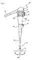
- Fig. 1 is an entire configuration diagram of an endoscope according to a first embodiment of the invention
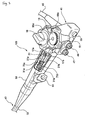
- Fig. 2 is a partially cutaway perspective view of an operating portion shown in Fig. 1
- description will be made with the same reference numerals being given to the same members as the members shown in Fig. 12 .
- An endoscope 100 includes an operating portion 41, and an insertion portion 43 connected to the operating portion 41 and inserted into an abdominal cavity.
- a universal cable 45 is connected to the operating portion 41, and a light guide connector (not shown) is provided at the tip of the universal cable 45.
- the light guide connector is detachably connected to a light source, and illumination light is sent to an illumination optical system at a tip 43a of the insertion portion.
- an electrical connector is connected to the light guide connector, and this electrical connector is detachably connected to a processor.
- An air supply/water supply button 47, a suction button 49, a shutter button 51, and a function switching button 53 are provided in parallel in the operating portion 41, and angle knobs 55a and 55b that are a pair of operating means are provided in the operating portion.
- the operating portion 41 is formed with a connecting portion 59 connected to the insertion portion 43, and the connecting portion 59 has a forceps insertion portion 61. By inserting a treatment instrument, such as forceps, into forceps insertion portion 61, this treatment instrument is led out from a forceps port (not shown) of the tip 43a of the insertion portion.
- a pulley 13 is provided inside the operating portion 41, and the pulley 13 is fixed to one, for example, angle knob 55a coaxially with a rotary shaft 15.
- a pair of operating wires 17a and 17b that are bending operating wires is wound around the pulley 13, and the operating wires 17a and 17b are connected to angular pipe-shaped sleeves 21a and 21b that are wire-connecting members 21 arranged on the side of the insertion portion 43.
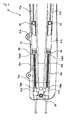
- Fig. 3 is an enlarged plan view of the inside of the operating portion shown in Fig. 2 .
- Slip-off preventing members 23 are respectively housed inside the sleeves 21a and 21b so as to be movable in an axial direction, and the slip-off preventing members are respectively connected to ends of the operating wires 17a and 17b. That is, the operating wires 17a and 17b are connected to the sleeves 21a and 21b with the play equivalent to the movement of the slip-off preventing members 23. Ends of driving wires 25a and 25b that are bending operating wires are respectively fixed to the other ends of the sleeves 21a and 21b.
- Fig. 4 is a sectional view of a sleeve. Since the connection structures of the sleeves 21 a and 21b are the same, one sleeve 21a will be described here as an example.
- the sleeve 21 a is angular pipe-shaped, and has inside dimensions such that the sleeve may house the slip-off preventing member 23.
- An opening at one end of the sleeve 21 a is made narrower than the slip-off preventing member 23, and the operating wire 17a may be inserted through the opening, but the slip-off preventing members 23 does not slip off.
- the operating wire 17a is connected to the sleeve 21a by such a slip-off preventing mechanism without being separated from the sleeve.
- the operating wire 17a becomes movable in the axial direction within the sleeve 21 a.
- a threaded portion 63 is formed in an inner wall of the sleeve 21 a opposite the aforementioned slip-off preventing mechanism.
- the tip of the driving wire 25a is anchored to an engaging tube 65 by soldering or the like.
- the engaging tube 65 is inserted into a screw member 67, and the screw member 67 is screwed to the threaded portion 63 of the sleeve 21 a.
- the end of the engaging tube 65 opposite the sleeve 21 a protrudes from the screw member 67, and a threaded groove is formed at an outer periphery of the protruding portion.
- the engaging tube 65 is fixed to the screw member 67 as a nut 69 is screwed to the threaded groove.
- the end of the engaging tube 65 on the side of the sleeve 21 a is prevented from slipping out by making its enlarged diameter portion abut on a stepped portion of the screw member 67.
- the driving wire 25a is fixed to the sleeve 21a, the operating wire 17a becomes movable with respect to the sleeve 21a.
- the driving wire 25a and the operating wire 17a are connected with the play equivalent to the movement of the slip-off preventing member 23.
- a bracket 29 shown in Fig. 3 is fixed to the portion of the operating portion 41 on the side of the insertion portion 43, and the bracket 29 fixes wire-receiving members 31 a and 31b which allow the driving wires 25a and 25b to be movably inserted therethrough.
- the driving wires 25a and 25b fixed to the sleeves 21a and 21b, respectively, are inserted through the wire-receiving members 31a and 31 b, respectively, push in the direction of the tip through a flexible portion 33 (refer to Fig. 1 ) of the insertion portion 43, and are connected to a bending portion 71 at their ends.
- the angle knob 55a bends the bending portion 71 right and left.
- the angle knob 55b bends the bending portion 71 up and down.
- the pulley, operating wire, sleeve, and driving wire (not shown) as the above ones are connected to the angle knob 55b, and these wire-connecting members are disposed at a lower layer of the connection structure shown in Fig. 2 (not shown).
- the slip-off preventing member 23 moves to a range within the sleeve 21a, for example, when the operating wire 17a is pushed toward the insertion portion 43. This movement becomes a play, and consequently the smooth bending of the bending portion 71 is enabled.
- a coil spring 73a or 73b which cover wire surfaces are externally inserted onto the driving wire 25a or 25b between the wire-receiving member 31a or 31b and the sleeve 21a or 21b.
- the coil springs 73a and 73b for example, coil springs obtained by spirally winding a wire rod with a circular cross-section may be used.
- the ends of the coil springs 73a and 73b become free ends which are not fixed only by covering the coil springs on the outer peripheries of the driving wires 25a and 25b.
- the internal diameter of the coil springs 73a and 73b be larger than a wire diameter to such an extent that sliding resistance with the driving wires 25a and 25b is not produced. Additionally, it is preferable that a gap be formed between pitches of wound wire rods, i.e., a structure where the springs may be retracted in an axial direction.
- Fig. 5 is an explanatory view of the operation of the first embodiment.
- the outer periphery of the wire is covered with the coil spring 73a between the wire-receiving member 31a and the sleeve 21a, and the deflection is regulated. If the distance between the wire-receiving member 31 a and the sleeve 21 a becomes shorter than the total length of the coil spring 73a, the coil spring 73a will cover the total length of the driving wire 25a while being compressed.
- the coil springs 73a and 73b are externally inserted onto the driving wires 25a and 25b between the wire-receiving members 31 a and 31 b, which are fixed to the portion of the operating portion 41 on the side of the insertion portion 43 and allows the driving wires 25a and 25b to be movably inserted therethrough, and the sleeves 21a and 21b.
- the deflection is regulated because the outer peripheries of the wires are covered with the coil springs 73a and 73b even if the reaction force of the push acts on the driving wires 25a and 25b and any one of the driving wires 25a and 25b is going to deflect.
- meandering of the driving wires 25a and 25b may be prevented, and any damage of the wires may be prevented.
- Fig. 6 is an enlarged plan view of the inside of an operating portion according to the second embodiment to which coil springs are fixed
- Fig. 7 is an explanatory view of the operation of the second embodiment.
- the same reference numerals will be given to the same members as the members shown in Figs. 1 to 5 , and duplicate description will be omitted.
- one ends (left ends) 73aL and 73bL of the coil springs 73a and 73b are fixed to the wire-receiving members 31 a and 31 b, respectively, and the other ends (right ends) 73aR and 73bR thereof are fixed to the sleeves 21a and 21b, respectively.
- both ends of the coil springs 73a and 73b are fixed to the wire-receiving members 31a and 31 b and the sleeves 21 a and 21b.
- the fixation may be made with an initial tension being further given to the coil springs 73a and 73b. That is, both the coil springs 73a and 73b are made to have an initial tension and are fixed in an equilibrium state shown in Fig. 6 such that the sleeves 21 a and 21b are drawn toward the wire-receiving member 31 a and 31b.
- Fig. 7 when the angle knob 55a is operated and the operating wire 17a is pushed to the left, the sleeve 21 a is pulled toward the wire-receiving member 31a by the initial tension of the coil springs 73a and 73b, and the sleeve 21a moves to the left.
- the slip-off preventing member 23 is kept abutting on the right end of the sleeve 21a. Thereby, a tension always acts on the operating wire 17a, and thus, any deflection is not produced and meandering of the operating wire 17a is prevented.
- the coil spring 73b pulls the sleeve 21b in a direction reverse to its pushed direction, the operating force by the angle knob 55a is sufficiently larger than this pull force, and therefore, there is no particular hindrance.
- Fig. 8 is an enlarged plan view the inside of an operating portion according to the third embodiment in which compression spring members are provided inside sleeves, respectively, Fig. 9 is an explanatory view of the operation of the third embodiment, and Fig. 10 is an explanatory view showing the operation of a compression spring member.
- compression spring members 75a and 75b which biases the slip-off preventing members 23 toward the operating wires 17a and 17b are provided inside the sleeves 21a and 21b, respectively.
- the compression spring members 75a and 75b may be coil springs which are housed in a compressed state. A left end of each spring member abuts on the engaging tube 65, and the other end thereof abuts on the slip-off preventing member 23.
- the compression spring members 75a and 75b may be proper spring members, such as leaf springs, besides the coil springs.
- the slip-off preventing member 23 of the operating wire 17a presses the compression spring member 75a within the sleeve 21a.
- a pressing force on the side of the insertion portion (left direction) is applied to the slip-off preventing member 23 as shown in Fig. 10A , the driving wire 25a is pushed while the compression spring member 75a is once compressed as shown in Fig. 10B .
- the sleeve 21a is pulled back to the insertion portion (left side) as shown in Fig. 10C by the restoring force of the compression spring member 75a, and a gap is eliminated between the slip-off preventing member 23 and the sleeve 21 a.
- the response when the operating wire 17a is pulled toward the operating portion (right side) is increased.
- the sagging amount of the operating wire 17a which is caused when the operating wire 17a is pushed toward the insertion portion (left side) is absorbed as the slip-off preventing members 23 moves within the sleeve 21a.
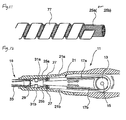
- Fig. 11 is a side view showing a modification of the coil spring.
- the coil spring may also be, for example, a coil spring 77 formed by spirally winding a strip material having a spring property shown in Fig. 11 .
- the area of contact with the driving wires 25a and 25b may be increased, thereby guiding the driving wires 25a and 25b so as to more hardly deflect, and consequently, making it harder to cause meandering.
Landscapes
- Health & Medical Sciences (AREA)
- Life Sciences & Earth Sciences (AREA)
- Physics & Mathematics (AREA)
- Surgery (AREA)
- Optics & Photonics (AREA)
- Biomedical Technology (AREA)
- Animal Behavior & Ethology (AREA)
- Radiology & Medical Imaging (AREA)
- Nuclear Medicine, Radiotherapy & Molecular Imaging (AREA)
- Engineering & Computer Science (AREA)
- Biophysics (AREA)
- Heart & Thoracic Surgery (AREA)
- Medical Informatics (AREA)
- Molecular Biology (AREA)
- Pathology (AREA)
- General Health & Medical Sciences (AREA)
- Public Health (AREA)
- Veterinary Medicine (AREA)
- Astronomy & Astrophysics (AREA)
- General Physics & Mathematics (AREA)
- Endoscopes (AREA)
- Instruments For Viewing The Inside Of Hollow Bodies (AREA)
Abstract
Description
- The present invention claims priority from Japanese Patent Application No.
2008-011323 filed on January 22, 2008 - The present invention relates to an endoscope having a bending portion capable of being bent by wires, and particularly, to an improved technique of preventing meandering of the wires.
- An endoscope is composed roughly of an insertion portion inserted into an abdominal cavity or the like, and an operating portion to which a proximal end of this insertion portion is connected. In the insertion portion, a distal end including an image pick-up unit or the like, a bending portion which may be bent, and a long flexible portion which constitutes the proximal end of the insertion portion and is connected to the operation portion are sequentially connected toward the operating portion from the distal side. An operating mechanism for operating the bending portion provided in the insertion portion operates the bending portion by push and pull of wires which are arranged in a pair. As for the pair of wires, typically, a driving wire from the insertion portion and an operating wire from an angle knob that is an operating means are connected together within the operating portion (refer to
JP-A-7-23892 JP-A-2003-290138 -
Fig. 12 is a sectional view of an operating portion showing a connection structure in an endoscope. - A
pulley 13 is provided inside anoperating portion 11, and thepulley 13 is fixed to an angle knob (not shown), which is rotatably provided at a side portion of theoperating portion 11, coaxially with arotary shaft 15. A pair ofoperating wires pulley 13, and theoperating wires insertion portion 19, and are connected to one ends of angular pipe-shaped sleeves members 21. Slip-off preventing members 23 (refer toFigs. 13A and 13B ) are respectively housed inside thesleeves operating wires off preventing members 23. That is, theoperating wires sleeves off preventing members 23. - Ends of
driving wires sleeves nut members 27. Abracket 29 is fixed to the portion of theoperating portion 11 on the side of theinsertion portion 19, and thebracket 29 fixes wire-receivingmembers driving wires driving wires sleeves members flexible portion 33 of theinsertion portion 19, and are connected to a bending portion (not shown) which becomes a distal end of theinsertion portion 19. Thereby, when the angle knob is rotated, theoperating wires pulley 13, thedriving wires sleeves insertion portion 19 is bent in a predetermined direction. - However, since the
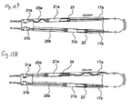
driving wires operating wires sleeves insertion portion 19, and the wires are exposed as they are between the wire-receivingmembers sleeves sleeves pulley 13, this connection structure is vulnerable to an axial compressive force. That is, as shown inFig. 13A , when delivery resistance is stronger at theinsertion portion 19 than the wire-receivingmembers driving wires member 31a and thesleeves 21a meandered due to deflection. On the other hand, as shown inFig. 13B , when the movement resistance of thesleeves operating wire 17a between thesleeve 21a and thepulley 13 meandered due to deflection. If such meandering is repeated frequently, there is a probability that the wires may be damaged by fatigue. In contrast, it is also conceivable that the wires are housed in tubes having rigidity in order to regulate meandering. However, when regions where the wires become naked are eliminated, play may not be given to wire length, and the flexibility of theinsertion portion 19 may not be maintained. Additionally, if thesleeves driving wires members sleeves sleeves - The invention is made in consideration of the above situations, and an object of the invention is to provide an endoscope capable of preventing meandering of a bending operating wire by simple structure, and thereby, preventing any damage of the wire.
- The above object according to the invention is achieved by the following configurations.
- According to a first aspect of the invention, an endoscope includes an insertion portion which has a bending portion, a wire which is fixed to an end of a distal side of the bending portion and is pushed along the insertion portion, an operating portion which is provided on a proximal side of the insertion portion opposite to the bending portion, the operating portion configured to perform a push and pull operation of the wire, a wire-connecting member which is interposed in the wire between the insertion portion and the operating portion to form an allowance in a in which the wire is pushed and pulled, a wire-receiving member which is arranged on an insertion-portion side of the operating portion, the wire being movably inserted through the wire-receiving member to be movable, and a coil spring, wherein a portion of the wire between the wire-receiving member and the wire-connecting member is inserted into the coil spring so that the coil covers a surface of the portion of the wire.
- According to this endoscope, even if one of wires on the operating portion is pushed toward the insertion portion and the reaction force of the push acts on the wire, and the wire is going to deflect, the deflection of the wire is regulated because the outer periphery of the wire is covered with the coil spring between the wire-receiving member and the wire-connecting member. Thereby, meandering of the wire between the wire-receiving member and the wire-connecting member is prevented.
- According to a second aspect of the invention, one end of the coil spring is fixed to the wire-receiving member, and the other end of the coil spring is fixed to the wire-connecting member.
- According to this endoscope, both ends of the coil spring are fixed to the wire-receiving member and the wire-connecting member. Thereby, even if the distance between the wire-receiving member and the wire-connecting member changes with the push and pull operations of the wire, the length of the coil spring makes a resilient change with this change, and the total wire length between the wire-receiving member and the wire-connecting member is always covered with the coil spring.
- According to a third aspect of the invention, the coil spring is fixed in a state where an initial tension is given thereto.
- According to this endoscope, the wire-connecting member is pulled toward the wire-receiving member by the initial tension of the coil spring, and a tension always acts on the wire on the side of the operating portion, thereby eliminating any deflection in the wire. This prevents meandering of the operating wire.
- According to a forth aspect of the invention, the wire-connecting member connects a driving wire portion that is the wire on the insertion-portion side, and an operating wire portion that is the wire on an operating-portion side together, and wherein the wire-connecting member includes, a sleeve connected to an end of the driving wire portion, and a slip-off preventing member that is connected to the operating wire, is movable in the direction of push and pull within the sleeve, and is accommodated in the sleeve, and the sleeve and the split-off preventing member form a slip-off preventing structure that prevents the operating wire from slipping off from the sleeve.
- According to this endoscope, the slip-off preventing member moves to a range within the sleeve when the operating wire is pushed toward the insertion portion. This movement becomes a play, and consequently the flexibility of the insertion portion is maintained.
- According to a fifth aspect of the invention, a compression spring member arranged within the sleeve and biased the slip-off preventing member toward the operating wire.
- According to this endoscope, when the operating wire is pushed, and the driving wire is pushed via the wire-connecting member, the slip-off preventing member of the operating wire presses and compresses the compression spring member within the wire-connecting member. Additionally, since the compression spring member pushes the slip-off preventing member back to the operating portion by its restoring force when operation is stopped, a gap is eliminated between the slip-off preventing member and the wire-connecting member. This enhances the response when the operating wire is pulled. Additionally, even when the operating wire is pushed toward the insertion portion, the slip-off preventing member may move within the wire-connecting member to absorb the amount of sagging of the driving wire.
- According to the endoscope related to the invention, when a wire on the operating portion is pushed toward the insertion portion, the deflection of the wire is regulated because the outer periphery of the wire is covered with the coil spring between the wire-receiving member and the wire-connecting member even if the reaction force of the extension acts on the wire, and the wire is going to deflect. Thereby, with simple structure, meandering of the bending operating wire may be prevented, and any damage of the wire may be prevented.
- Other aspects and advantages of the invention will be apparent from the following description and the appended claims.
-
-
Fig. 1 is an entire configuration diagram of an endoscope according to a first embodiment of the invention; -
Fig. 2 is a partially cutaway perspective view of an operating portion shown inFig. 1 ; -
Fig. 3 is an enlarged plan view of the inside of the operating portion shown inFig. 2 ; -
Fig. 4 is a sectional view of a sleeve; -
Fig. 5 is an explanatory view of the operation of the first embodiment; -
Fig. 6 is an enlarged plan view of the inside of an operating portion according to a second embodiment to which coil springs are fixed; -
Fig. 7 is an explanatory view of the operation of the second embodiment; -
Fig. 8 is an enlarged plan view of the inside of an operating portion according to a third embodiment in which compression spring members are provided inside sleeves, respectively; -
Fig. 9 is an explanatory view of the operation of the third embodiment; -
Fig. 10A is an explanatory view showing the operation of a compression spring member; -
Fig. 10B is an explanatory view showing the operation of a compression spring member; -
Fig. 10C is an explanatory view showing the operation of a compression spring member; -
Fig. 10D is an explanatory view showing the operation of a compression spring member; -
Fig. 11 is a side view showing a modification of the coil spring; -
Fig. 12 is a plan view of the inside of an operating portion in an endoscope; -
Fig. 13A is a plan view of the inside of the operating portion, showing a wire meandering situation; and -
Fig. 13B is a plan view of the inside of the operating portion, showing a wire meandering situation. - Hereinafter, preferred embodiments of an endoscope according to the invention will be described in detail with reference to the accompanying drawings.
-
Fig. 1 is an entire configuration diagram of an endoscope according to a first embodiment of the invention, andFig. 2 is a partially cutaway perspective view of an operating portion shown inFig. 1 . In addition, description will be made with the same reference numerals being given to the same members as the members shown inFig. 12 . - An
endoscope 100 includes an operatingportion 41, and aninsertion portion 43 connected to the operatingportion 41 and inserted into an abdominal cavity. Auniversal cable 45 is connected to the operatingportion 41, and a light guide connector (not shown) is provided at the tip of theuniversal cable 45. The light guide connector is detachably connected to a light source, and illumination light is sent to an illumination optical system at atip 43a of the insertion portion. Additionally, an electrical connector is connected to the light guide connector, and this electrical connector is detachably connected to a processor. - An air supply/
water supply button 47, asuction button 49, ashutter button 51, and afunction switching button 53 are provided in parallel in the operatingportion 41, andangle knobs portion 41 is formed with a connectingportion 59 connected to theinsertion portion 43, and the connectingportion 59 has aforceps insertion portion 61. By inserting a treatment instrument, such as forceps, intoforceps insertion portion 61, this treatment instrument is led out from a forceps port (not shown) of thetip 43a of the insertion portion. - A
pulley 13 is provided inside the operatingportion 41, and thepulley 13 is fixed to one, for example,angle knob 55a coaxially with arotary shaft 15. A pair ofoperating wires pulley 13, and theoperating wires sleeves members 21 arranged on the side of theinsertion portion 43. -
Fig. 3 is an enlarged plan view of the inside of the operating portion shown inFig. 2 . - Slip-
off preventing members 23 are respectively housed inside thesleeves operating wires operating wires sleeves members 23. Ends of drivingwires sleeves - Here, the wire connection structure by the
sleeves -
Fig. 4 is a sectional view of a sleeve. Since the connection structures of thesleeves sleeve 21a will be described here as an example. Thesleeve 21 a is angular pipe-shaped, and has inside dimensions such that the sleeve may house the slip-off preventingmember 23. An opening at one end of thesleeve 21 a is made narrower than the slip-off preventingmember 23, and theoperating wire 17a may be inserted through the opening, but the slip-off preventingmembers 23 does not slip off. Theoperating wire 17a is connected to thesleeve 21a by such a slip-off preventing mechanism without being separated from the sleeve. - The
operating wire 17a becomes movable in the axial direction within thesleeve 21 a. A threadedportion 63 is formed in an inner wall of thesleeve 21 a opposite the aforementioned slip-off preventing mechanism. The tip of thedriving wire 25a is anchored to an engagingtube 65 by soldering or the like. The engagingtube 65 is inserted into ascrew member 67, and thescrew member 67 is screwed to the threadedportion 63 of thesleeve 21 a. The end of the engagingtube 65 opposite thesleeve 21 a protrudes from thescrew member 67, and a threaded groove is formed at an outer periphery of the protruding portion. The engagingtube 65 is fixed to thescrew member 67 as anut 69 is screwed to the threaded groove. On the other hand, the end of the engagingtube 65 on the side of thesleeve 21 a is prevented from slipping out by making its enlarged diameter portion abut on a stepped portion of thescrew member 67. - By adopting the above configuration as the connection structure of the
operating wire 17a and thedriving wire 25a, thedriving wire 25a is fixed to thesleeve 21a, theoperating wire 17a becomes movable with respect to thesleeve 21a. As a result, thedriving wire 25a and theoperating wire 17a are connected with the play equivalent to the movement of the slip-off preventingmember 23. - A
bracket 29 shown inFig. 3 is fixed to the portion of the operatingportion 41 on the side of theinsertion portion 43, and thebracket 29 fixes wire-receivingmembers wires wires sleeves members Fig. 1 ) of theinsertion portion 43, and are connected to a bendingportion 71 at their ends. Thereby, when theangle knob 55a is rotated, theoperating wires pulley 13, the drivingwires sleeves portion 71 of theinsertion portion 43 is bent in a predetermined direction. - The
angle knob 55a bends the bendingportion 71 right and left. On the other hand, theangle knob 55b bends the bendingportion 71 up and down. The pulley, operating wire, sleeve, and driving wire (not shown) as the above ones are connected to theangle knob 55b, and these wire-connecting members are disposed at a lower layer of the connection structure shown inFig. 2 (not shown). In such connection structure, the slip-off preventingmember 23 moves to a range within thesleeve 21a, for example, when theoperating wire 17a is pushed toward theinsertion portion 43. This movement becomes a play, and consequently the smooth bending of the bendingportion 71 is enabled. - A
coil spring driving wire member sleeve coil springs coil springs wires coil springs wires -
Fig. 5 is an explanatory view of the operation of the first embodiment. - In the above configuration, for example, when the
angle knob 55a is operated and thepulley 13 is rotated counterclockwise, thelower operating wire 17b is delivered to the right ofFig. 5 , and the slip-off preventingmembers 23 moves to the right, and thesleeve 21b moves to the right. At this time, the bending portion is bent, and accordingly, theupper operating wire 25a is pulled from the insertion portion 43 (refer toFigs. 1 and2 ). Thereby, thedriving wire 25a pressed by thesleeve 21a is introduced into the wire-receivingmember 31a, and is pushed to theinsertion portion 43. In this case, even if the reaction force of the push in theinsertion portion 43 acts on thedriving wire 25a, and thedriving wire 25a is going to deflect, the outer periphery of the wire is covered with thecoil spring 73a between the wire-receivingmember 31a and thesleeve 21a, and the deflection is regulated. If the distance between the wire-receivingmember 31 a and thesleeve 21 a becomes shorter than the total length of thecoil spring 73a, thecoil spring 73a will cover the total length of thedriving wire 25a while being compressed. - Accordingly, according to the
above endoscope 100, thecoil springs wires members portion 41 on the side of theinsertion portion 43 and allows the drivingwires sleeves operating wires portion 41 is pushed toward theinsertion portion 43, the deflection is regulated because the outer peripheries of the wires are covered with thecoil springs wires wires wires - Next, a second embodiment of the endoscope according to the invention will be described.
-
Fig. 6 is an enlarged plan view of the inside of an operating portion according to the second embodiment to which coil springs are fixed, andFig. 7 is an explanatory view of the operation of the second embodiment. In addition, in the following respective embodiments, the same reference numerals will be given to the same members as the members shown inFigs. 1 to 5 , and duplicate description will be omitted. In this endoscope, one ends (left ends) 73aL and 73bL of thecoil springs members sleeves - According to this endoscope, both ends of the
coil springs members sleeves members sleeves coil springs members sleeves coil springs - In this embodiment, the fixation may be made with an initial tension being further given to the
coil springs coil springs Fig. 6 such that thesleeves member Fig. 7 , when theangle knob 55a is operated and theoperating wire 17a is pushed to the left, thesleeve 21 a is pulled toward the wire-receivingmember 31a by the initial tension of thecoil springs sleeve 21a moves to the left. Then, the slip-off preventingmember 23 is kept abutting on the right end of thesleeve 21a. Thereby, a tension always acts on theoperating wire 17a, and thus, any deflection is not produced and meandering of theoperating wire 17a is prevented. In addition, although thecoil spring 73b pulls thesleeve 21b in a direction reverse to its pushed direction, the operating force by theangle knob 55a is sufficiently larger than this pull force, and therefore, there is no particular hindrance. - Next, a third embodiment of the endoscope according to the invention will be described.
-
Fig. 8 is an enlarged plan view the inside of an operating portion according to the third embodiment in which compression spring members are provided inside sleeves, respectively,Fig. 9 is an explanatory view of the operation of the third embodiment, andFig. 10 is an explanatory view showing the operation of a compression spring member. - In this endoscope, as shown in
Fig. 8 ,compression spring members members 23 toward theoperating wires sleeves compression spring members tube 65, and the other end thereof abuts on the slip-off preventingmember 23. Thecompression spring members - According to this endoscope, as shown in
Fig. 9 , for example, when theoperating wire 17a is delivered and thedriving wire 25a is pushed via thesleeve 21 a, the slip-off preventingmember 23 of theoperating wire 17a presses thecompression spring member 75a within thesleeve 21a. When a pressing force on the side of the insertion portion (left direction) is applied to the slip-off preventingmember 23 as shown inFig. 10A , thedriving wire 25a is pushed while thecompression spring member 75a is once compressed as shown inFig. 10B . - Almost simultaneously with stop of the extension, the
sleeve 21a is pulled back to the insertion portion (left side) as shown inFig. 10C by the restoring force of thecompression spring member 75a, and a gap is eliminated between the slip-off preventingmember 23 and thesleeve 21 a. Thereby, as shown inFig. 10D , the response when theoperating wire 17a is pulled toward the operating portion (right side) is increased. Additionally, even by this configuration, the sagging amount of theoperating wire 17a which is caused when theoperating wire 17a is pushed toward the insertion portion (left side) is absorbed as the slip-off preventingmembers 23 moves within thesleeve 21a. - In addition, although coil spring formed by spirally winding wire rods with a circular cross-section are used as the
coil springs Fig. 11 is a side view showing a modification of the coil spring. The coil spring may also be, for example, acoil spring 77 formed by spirally winding a strip material having a spring property shown inFig. 11 . By using thecoil spring 77 made of such a strip material, the area of contact with the drivingwires wires
Claims (5)
- An endoscope comprising:an insertion portion which has a bending portion;a wire which is fixed to an end of a distal side of the bending portion and is pushed along the insertion portion,an operating portion which is provided on a proximal side of the insertion portion opposite to the bending portion, the operating portion configured to perform a push and pull operation of the wire;a wire-connecting member which is interposed in the wire between the insertion portion and the operating portion to form an allowance in a in which the wire is pushed and pulled;a wire-receiving member which is arranged on an insertion-portion side of the operating portion, the wire being movably inserted through the wire-receiving member to be movable; anda coil spring, wherein a portion of the wire between the wire-receiving member and the wire-connecting member is inserted into the coil spring so that the coil covers a surface of the portion of the wire.
- The endoscope according to Claim 1,
wherein one end of the coil spring is fixed to the wire-receiving member, and the other end of the coil spring is fixed to the wire-connecting member. - The endoscope according to Claim 2,
wherein the coil spring is fixed in a state where an initial tension is given thereto. - The endoscope according to any one of Claims 1 to 3,
wherein the wire-connecting member connects a driving wire portion that is the wire on the insertion-portion side, and an operating wire portion that is the wire on an operating-portion side together, and
wherein the wire-connecting member includes,
a sleeve connected to an end of the driving wire portion,
and
a slip-off preventing member that is connected to the operating wire, is movable in the direction of push and pull within the sleeve, and is accommodated in the sleeve, and the sleeve and the split-off preventing member form a slip-off preventing structure that prevents the operating wire from slipping off from the sleeve. - The endoscope according to Claim 4, further comprising:a compression spring member arranged within the sleeve and biased the slip-off preventing member toward the operating wire.
Applications Claiming Priority (1)
| Application Number | Priority Date | Filing Date | Title |
|---|---|---|---|
| JP2008011323A JP5105605B2 (en) | 2008-01-22 | 2008-01-22 | Endoscope |
Publications (2)
| Publication Number | Publication Date |
|---|---|
| EP2082679A2 true EP2082679A2 (en) | 2009-07-29 |
| EP2082679A3 EP2082679A3 (en) | 2010-08-04 |
Family
ID=40456778
Family Applications (1)
| Application Number | Title | Priority Date | Filing Date |
|---|---|---|---|
| EP09000869A Withdrawn EP2082679A3 (en) | 2008-01-22 | 2009-01-22 | Flexible endoscope |
Country Status (4)
| Country | Link |
|---|---|
| US (1) | US8308634B2 (en) |
| EP (1) | EP2082679A3 (en) |
| JP (1) | JP5105605B2 (en) |
| CN (1) | CN101491429B (en) |
Cited By (1)
| Publication number | Priority date | Publication date | Assignee | Title |
|---|---|---|---|---|
| WO2019093968A1 (en) * | 2017-11-09 | 2019-05-16 | Endomaster Pte Ltd. | Endoscopy system |
Families Citing this family (20)
| Publication number | Priority date | Publication date | Assignee | Title |
|---|---|---|---|---|
| JP5349388B2 (en) * | 2010-03-29 | 2013-11-20 | 富士フイルム株式会社 | Endoscope operation wire connecting device and endoscope |
| EP2578139B1 (en) * | 2011-03-08 | 2014-08-27 | Olympus Medical Systems Corp. | Insertion device |
| USD668762S1 (en) * | 2011-03-31 | 2012-10-09 | Karl Storz Gmbh & Co. Kg | Handle for medical device |
| USD669175S1 (en) * | 2011-03-31 | 2012-10-16 | Karl Storz Gmbh & Co. Kg | Handle for medical device |
| JP5253689B1 (en) * | 2011-07-15 | 2013-07-31 | オリンパスメディカルシステムズ株式会社 | Insertion equipment |
| JP5826862B2 (en) * | 2012-01-16 | 2015-12-02 | オリンパス株式会社 | Insertion device |
| JP6025401B2 (en) * | 2012-05-31 | 2016-11-16 | キヤノン株式会社 | Medical instruments |
| US20140018620A1 (en) * | 2012-07-13 | 2014-01-16 | Fortimedix B.V. | Steerable tube for endoscopic applications |
| SG2013002837A (en) * | 2013-01-14 | 2014-08-28 | Sg Endoscopy Pte Ltd | Bending operation apparatus for endoscope and endoscope |
| WO2015057195A1 (en) * | 2013-10-15 | 2015-04-23 | Stryker Corporation | Device for creating a void space in a living tissue, the device including a handle with a control knob that can be set regardless of the orientation of the handle |
| JP2015093033A (en) * | 2013-11-12 | 2015-05-18 | 住友ベークライト株式会社 | Medical device |
| WO2015118705A1 (en) * | 2014-02-07 | 2015-08-13 | オリンパス株式会社 | Endoscope |
| JP6205294B2 (en) * | 2014-02-28 | 2017-09-27 | オリンパス株式会社 | MEDICAL DEVICE, MEDICAL SYSTEM, AND METHOD OF OPERATING MEDICAL DEVICE |
| CN111990946A (en) * | 2014-08-29 | 2020-11-27 | 恩多巧爱思股份有限公司 | System and method for varying the stiffness of an endoscope insertion tube |
| JP6099853B1 (en) * | 2015-05-28 | 2017-03-22 | オリンパス株式会社 | Endoscope |
| EP3618689A4 (en) * | 2017-05-03 | 2021-02-17 | Canon U.S.A., Inc. | STEERABLE MEDICAL DEVICE AND PROCEDURE |
| WO2020219392A2 (en) | 2019-04-24 | 2020-10-29 | Stryker Corporation | Systems and methods for off-axis augmentation of a vertebral body |
| US11974722B2 (en) * | 2019-10-07 | 2024-05-07 | Boston Scientific Scimed, Inc. | Endoscopic device with interchangeable shaft |
| US20220202277A1 (en) * | 2020-12-30 | 2022-06-30 | Canon U.S.A., Inc. | Steerable medical device |
| CN114052624A (en) * | 2021-11-10 | 2022-02-18 | 深圳市宏济医疗技术开发有限公司 | Operating device of endoscope and endoscope |
Citations (3)
| Publication number | Priority date | Publication date | Assignee | Title |
|---|---|---|---|---|
| JPH0723892A (en) | 1993-07-07 | 1995-01-27 | Fuji Photo Optical Co Ltd | Connector in endoscope |
| JP2003290138A (en) | 2002-03-29 | 2003-10-14 | Fuji Photo Optical Co Ltd | Connecting structure of wire and connecting structure of curving operation wire of endoscope |
| JP2008011323A (en) | 2006-06-30 | 2008-01-17 | Matsushita Electric Ind Co Ltd | Operating speed detector |
Family Cites Families (15)
| Publication number | Priority date | Publication date | Assignee | Title |
|---|---|---|---|---|
| JPS6112961Y2 (en) * | 1978-04-12 | 1986-04-22 | ||
| DE3214615C2 (en) * | 1981-04-21 | 1985-04-25 | Kabushiki Kaisha Medos Kenkyusho, Tokio/Tokyo | Curvature control arrangement for an endoscope |
| US4688555A (en) * | 1986-04-25 | 1987-08-25 | Circon Corporation | Endoscope with cable compensating mechanism |
| US4762119A (en) * | 1987-07-28 | 1988-08-09 | Welch Allyn, Inc. | Self-adjusting steering mechanism for borescope or endoscope |
| JPH02283347A (en) * | 1989-04-25 | 1990-11-20 | Olympus Optical Co Ltd | Apparatus for bending operation of catheter |
| JP3109814B2 (en) * | 1990-04-09 | 2000-11-20 | 旭光学工業株式会社 | Endoscope |
| JPH05161596A (en) * | 1991-12-17 | 1993-06-29 | Mitsubishi Cable Ind Ltd | Structure for oscillating endoscope |
| US5299559A (en) * | 1992-03-13 | 1994-04-05 | Acuson Corporation | Endoscope with overload protective device |
| JPH07303601A (en) * | 1994-05-11 | 1995-11-21 | Toshiba Corp | Slack remover for curving operation wire in endoscope |
| JPH08160317A (en) * | 1994-12-09 | 1996-06-21 | Machida Endscope Co Ltd | Endoscope |
| US5762067A (en) | 1996-05-30 | 1998-06-09 | Advanced Technology Laboratories, Inc. | Ultrasonic endoscopic probe |
| JP4118402B2 (en) * | 1998-08-05 | 2008-07-16 | オリンパス株式会社 | Endoscope |
| US6717092B2 (en) | 2000-08-11 | 2004-04-06 | Pentax Corporation | Method of manufacturing treatment instrument of endoscope |
| US7811277B2 (en) | 2004-09-30 | 2010-10-12 | Boston Scientific Scimed, Inc. | Steerable device and system |
| US8287449B2 (en) | 2005-05-26 | 2012-10-16 | Ars Co., Ltd. | Endoscope device |
-
2008
- 2008-01-22 JP JP2008011323A patent/JP5105605B2/en not_active Expired - Fee Related
-
2009
- 2009-01-21 US US12/357,136 patent/US8308634B2/en not_active Expired - Fee Related
- 2009-01-22 CN CN200910002778.5A patent/CN101491429B/en not_active Expired - Fee Related
- 2009-01-22 EP EP09000869A patent/EP2082679A3/en not_active Withdrawn
Patent Citations (3)
| Publication number | Priority date | Publication date | Assignee | Title |
|---|---|---|---|---|
| JPH0723892A (en) | 1993-07-07 | 1995-01-27 | Fuji Photo Optical Co Ltd | Connector in endoscope |
| JP2003290138A (en) | 2002-03-29 | 2003-10-14 | Fuji Photo Optical Co Ltd | Connecting structure of wire and connecting structure of curving operation wire of endoscope |
| JP2008011323A (en) | 2006-06-30 | 2008-01-17 | Matsushita Electric Ind Co Ltd | Operating speed detector |
Cited By (2)
| Publication number | Priority date | Publication date | Assignee | Title |
|---|---|---|---|---|
| WO2019093968A1 (en) * | 2017-11-09 | 2019-05-16 | Endomaster Pte Ltd. | Endoscopy system |
| US11490973B2 (en) | 2017-11-09 | 2022-11-08 | Endomaster Pte Ltd | Endoscopy system |
Also Published As
| Publication number | Publication date |
|---|---|
| US8308634B2 (en) | 2012-11-13 |
| CN101491429B (en) | 2012-11-28 |
| JP2009172028A (en) | 2009-08-06 |
| US20090192357A1 (en) | 2009-07-30 |
| EP2082679A3 (en) | 2010-08-04 |
| CN101491429A (en) | 2009-07-29 |
| JP5105605B2 (en) | 2012-12-26 |
Similar Documents
| Publication | Publication Date | Title |
|---|---|---|
| US8308634B2 (en) | Endoscope | |
| US6582357B2 (en) | Treating instrument erecting device for use in endoscope | |
| JP4642936B2 (en) | Medical tube | |
| US9872607B2 (en) | Endoscope | |
| US11109745B2 (en) | Endoscope | |
| JP6157787B1 (en) | Endoscope | |
| JP5663709B1 (en) | Endoscope | |
| CN102469911A (en) | Insertion instrument endoscope | |
| US20150272425A1 (en) | Endoscope | |
| JP5021346B2 (en) | Endoscope guide tube and endoscope apparatus | |
| US20190208984A1 (en) | Endoscope | |
| CN110545708A (en) | endoscope bending section and endoscope | |
| JP5747365B1 (en) | Insertion device and endoscope | |
| US20110288375A1 (en) | Endoscope | |
| US20170224204A1 (en) | Signal line installation structure of elongated member | |
| JP6689589B2 (en) | Endoscope | |
| JP6223635B2 (en) | Endoscope | |
| JP2003000533A (en) | Endoscopic apparatus | |
| JP6402285B1 (en) | Endoscope | |
| JPH06300975A (en) | Curvable flexible pipe | |
| CN112423642B (en) | Endoscope with a lens | |
| WO2018207514A1 (en) | Endoscope | |
| JP2001269307A (en) | Endoscope bending device | |
| JPS644446B2 (en) | ||
| JPS6069620A (en) | Endoscope |
Legal Events
| Date | Code | Title | Description |
|---|---|---|---|
| PUAI | Public reference made under article 153(3) epc to a published international application that has entered the european phase |
Free format text: ORIGINAL CODE: 0009012 |
|
| AK | Designated contracting states |
Kind code of ref document: A2 Designated state(s): AT BE BG CH CY CZ DE DK EE ES FI FR GB GR HR HU IE IS IT LI LT LU LV MC MK MT NL NO PL PT RO SE SI SK TR |
|
| AX | Request for extension of the european patent |
Extension state: AL BA RS |
|
| PUAL | Search report despatched |
Free format text: ORIGINAL CODE: 0009013 |
|
| AK | Designated contracting states |
Kind code of ref document: A3 Designated state(s): AT BE BG CH CY CZ DE DK EE ES FI FR GB GR HR HU IE IS IT LI LT LU LV MC MK MT NL NO PL PT RO SE SI SK TR |
|
| AX | Request for extension of the european patent |
Extension state: AL BA RS |
|
| 17P | Request for examination filed |
Effective date: 20110202 |
|
| AKX | Designation fees paid |
Designated state(s): DE FR GB |
|
| STAA | Information on the status of an ep patent application or granted ep patent |
Free format text: STATUS: THE APPLICATION IS DEEMED TO BE WITHDRAWN |
|
| 18D | Application deemed to be withdrawn |
Effective date: 20140801 |