EP2082087B1 - Front-loading laundry washing machine - Google Patents
Front-loading laundry washing machine Download PDFInfo
- Publication number
- EP2082087B1 EP2082087B1 EP07858848A EP07858848A EP2082087B1 EP 2082087 B1 EP2082087 B1 EP 2082087B1 EP 07858848 A EP07858848 A EP 07858848A EP 07858848 A EP07858848 A EP 07858848A EP 2082087 B1 EP2082087 B1 EP 2082087B1
- Authority
- EP
- European Patent Office
- Prior art keywords
- washing machine
- duct
- laundry washing
- machine according
- distributor
- Prior art date
- Legal status (The legal status is an assumption and is not a legal conclusion. Google has not performed a legal analysis and makes no representation as to the accuracy of the status listed.)
- Active
Links
- 238000010412 laundry washing Methods 0.000 title claims abstract description 19
- XLYOFNOQVPJJNP-UHFFFAOYSA-N water Substances O XLYOFNOQVPJJNP-UHFFFAOYSA-N 0.000 claims abstract description 24
- 238000005406 washing Methods 0.000 claims abstract description 17
- 239000003795 chemical substances by application Substances 0.000 claims abstract description 8
- 239000003599 detergent Substances 0.000 description 3
- 239000004033 plastic Substances 0.000 description 3
- 229920003023 plastic Polymers 0.000 description 3
- 239000004743 Polypropylene Substances 0.000 description 2
- 230000000694 effects Effects 0.000 description 2
- 239000000463 material Substances 0.000 description 2
- -1 polypropylene Polymers 0.000 description 2
- 229920001155 polypropylene Polymers 0.000 description 2
- RYGMFSIKBFXOCR-UHFFFAOYSA-N Copper Chemical compound [Cu] RYGMFSIKBFXOCR-UHFFFAOYSA-N 0.000 description 1
- 229920000114 Corrugated plastic Polymers 0.000 description 1
- 229920002943 EPDM rubber Polymers 0.000 description 1
- 229910052802 copper Inorganic materials 0.000 description 1
- 239000010949 copper Substances 0.000 description 1
- 238000013016 damping Methods 0.000 description 1
- 238000001035 drying Methods 0.000 description 1
- 230000009977 dual effect Effects 0.000 description 1
- 239000007788 liquid Substances 0.000 description 1
- 239000007769 metal material Substances 0.000 description 1
- 239000000843 powder Substances 0.000 description 1
- 239000002244 precipitate Substances 0.000 description 1
- 238000010079 rubber tapping Methods 0.000 description 1
- 238000005303 weighing Methods 0.000 description 1
- 238000003466 welding Methods 0.000 description 1
Images

Classifications
-
- D—TEXTILES; PAPER
- D06—TREATMENT OF TEXTILES OR THE LIKE; LAUNDERING; FLEXIBLE MATERIALS NOT OTHERWISE PROVIDED FOR
- D06F—LAUNDERING, DRYING, IRONING, PRESSING OR FOLDING TEXTILE ARTICLES
- D06F39/00—Details of washing machines not specific to a single type of machines covered by groups D06F9/00 - D06F27/00
- D06F39/02—Devices for adding soap or other washing agents
- D06F39/028—Arrangements for selectively supplying water to detergent compartments
Definitions
- the present invention relates to a laundry washing machine according to the preamble of claim 1.
- the invention is applicable to the field of front-loading laundry washing machines (in particular washing and washing/drying machines) wherein the dispenser of washing agents (detergent, softener, etc.) is arranged in the door that closes the load opening of the machine: the invention also concerns the problem of the noise produced by such machines.
- Laundry washing machines are known from GB 1,110,375 and GB 2,260,770 wherein the washing agent dispenser is inserted in the door that closes the load opening.
- the hydraulic supply system comprises a duct which carries water from the household water main to the dispenser, through the gasket that surrounds the load opening between the tub and the cabinet of the washing machine.
- the duct is secured in just two points: to the control valve that regulates the water supply From the household water main on one side, and to a nozzle inserted in the gasket on the other side.
- the idea that ensures the achievement of this object is to constrain the duct that carries water to the dispenser to the cabinet of the washing machine.
- Fig. 1 shows a washing machine 1 from which the from wall and the upper wall (including the electronic unit and control panels) of the external structure, also called cabinet 2. have been removed for clarity.
- an oscillating assembly which comprises a tub 3 and a drum 4 turning within the tub.
- Washing machine 1 is of the front-loading type: the laundry is therefore placed into the drum through a load opening located on the front side of cabinet 2.
- the opening is surrounded by a bellows-type plastic gasket 6, which connects cabinet 2 to tub 3, thus filling up the existing interspace and preventing any water leakage from the tub.
- the load opening is closed by a door 7, which incorporates a washing agent dispenser 8.
- the latter has upper apertures 81 on which water is precipitated through a hydraulic system adapted to carry water from the household water main to dispenser 8.
- dispenser 8 has three apertures 81, which are associated with respective compartments adapted to contain different washing agents. e.g. softener, liquid detergent or powder detergent.
- washing agents e.g. softener, liquid detergent or powder detergent.
- filling apertures 81 are located in the area circumscribed externally by gasket 6, in from of the tub 3.
- gasket 6 has a seat 61 adapted to contain a distributor 9, shown in Fig. 3 .
- the latter essentially consists of a hollow body 90 within which there are channels 92 connecting water inlets 91 to water outlets 93.
- distributor 9 has two inlets 91 and four outlets 93, but of course the number of inlets and outlets may vary from the example of Fig. 3 .
- Water is supplied to distributor inlets 91 through a pair of corrupted pipes 10 connected thereto.
- pipes 10 are connected to a three-way solenoid valve 11 (i.e. having one inlet and two outlets) which regulates the water flow in both pipes 10 under the control of the electronic control unit of the washing machine.
- solenoid valve 11 i.e. having one inlet and two outlets
- corrugated pipes 10 are made of polypropylene; at the respective ends, they are provided with co-moulded fittings made of EPDM rubber, which ensure perfect water tightness and a stable connection between corrugated pipes 10 and solenoid valve 11 and between corrugated pipes 10 and distributor 9.
- Pipes 10 are constrained to cabinet 2 of the machine by means of a plurality of ties 12 which limit the movement thereof.
- Ties 12 preferably made from plastic material, are located on the front side of cabinet 2, near the load opening and distributor 9, as well as under the top of cabinet 2, in particular at the shoulder of cabinet 2 which supports the top wall thereof.
- ties 12 are inserted through holes obtained in a bent edge 77 of cabinet 2, thus ensuring that pipes 10 are clamped to cabinet 2.
- the damping of pipes 10 prevents them from jolting when the machine is operating, thus reducing the noise produced by the machine.
- the ties arranged near distributor 9 have the dual purpose of clamping both pipes 10 and distributor 9. It follows that, when gasket 6 moves through the effect of the laundry being present inside drum 4 and of the vibrations of the oscillating assembly taking place during the operation of the machine, distributor 9 will be kept in a predetermined position above dispenser 8.
- any malfunctioning of the machine will thus be avoided.
- any movement of distributor 9 caused by vibrations of pipes 10 and of the oscillating assembly might cause water to be mistakenly precipitated onto a compartment of the dispenser 8 which should not be flushed yet (e.g. the softener compartment before the wash cycle is over).
- tics 12 prevent pipes 10 and the water contained therein from weighing upon gasket 6. thereby deforming it.
- distributor 9 is secured to cabinet 2.
- one or more holes are obtained in the distributor for the purpose of housing fastening screws inserted through holes obtained in the front wall of cabinet 2: distributor 9 is therefore secured to cabinet 2 through the effect of the tightening force applied to the screws, which presses the front wall of cabinet 2 against distributor 9.
- distributor 9 is made from plastic, self-tapping screws may be used.
- the laundry washing machine according to the present invention is thus more efficient and less subject to wear.
- ties 12 may be replaced with any other securing means (such as hooks, collars, forks, etc.), which may be used in any number and in any location as deemed necessary.
- these securing means must provide as a whole a stable fixing of pipes to to cabinet 2 of the washing machine 1: advantageously, pipes 10 may be secured on at least two sides (one of which is the front wall) of cabinet 2.
- Pipes 10 are preferably flexible, e.g. corrugated plastic pipes (preferably made of polypropylene or PVC), but they may alternatively be replaced wholly or partly with rigid ducts made of any material, including metal materials such as copper.
- corrugated plastic pipes preferably made of polypropylene or PVC
- rigid ducts made of any material, including metal materials such as copper.
- the fixing may then be obtained through said securing means or else by welding said pipes to the cabinet of the washing machine.
- the dispenser and the hydraulic system may be made even simpler, for example by using a single water supply duct as in patents GB 1,110,375 and GB 2,260,770 .
- the distributor may be at simple nozzle.
Landscapes
- Engineering & Computer Science (AREA)
- Textile Engineering (AREA)
- Detail Structures Of Washing Machines And Dryers (AREA)
- Accessory Of Washing/Drying Machine, Commercial Washing/Drying Machine, Other Washing/Drying Machine (AREA)
- Seasonings (AREA)
Abstract
Description
- The present invention relates to a laundry washing machine according to the preamble of claim 1.
- The invention is applicable to the field of front-loading laundry washing machines (in particular washing and washing/drying machines) wherein the dispenser of washing agents (detergent, softener, etc.) is arranged in the door that closes the load opening of the machine: the invention also concerns the problem of the noise produced by such machines.
- Laundry washing machines are known from
GB 1,110,375 GB 2,260,770 - In these machines, the hydraulic supply system comprises a duct which carries water from the household water main to the dispenser, through the gasket that surrounds the load opening between the tub and the cabinet of the washing machine.
- In both solutions, the duct is secured in just two points: to the control valve that regulates the water supply From the household water main on one side, and to a nozzle inserted in the gasket on the other side.
- These machines suffer from the problem that such a hydraulic system makes them very noisy and/or inefficient. If the duct is flexible, when the machine is operating it will be moved violently by the vibrations of the oscillating assembly to which it is connected through the gasket, thus becoming very noisy. If on the contrary the duct is a rigid one, it will not be able to absorb the vibrations of the oscillating assembly, thus leading to damage caused to the gasket or to the duct itself. The use of a rigid duct in the above-mentioned known configuration would not eliminate the noise due to the mechanical stress undergone by the connections between the duct and the gasket or the control valve.
- It is the object of the present invention to solve the above-mentioned noise and/or efficiency problems suffered by the solutions known in the art of laundry washing machines with washing agent dispenser in the door that closes the load opening.
- This object is achieved through a laundry washing machine incorporating the features set out in the appended claims, which are intended as an integral part of the present, description.
- In particular, the idea that ensures the achievement of this object is to constrain the duct that carries water to the dispenser to the cabinet of the washing machine.
- Further objects and advantages of the present invention will become apparent from the following description and from the annexed drawings, which are supplied by way of non-limiting example, wherein:
-
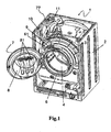
Fig. 1 is an axonometry projection of a laundry washing machine according to the present invention; -
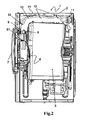
Fig. 2 is a longitudinal-section view of a laundry washing machine according to the present invention; -
Fig. 3 shows an element of the hydraulic system of a laundry washing machine according to the present invention. -
Fig. 1 shows a washing machine 1 from which the from wall and the upper wall (including the electronic unit and control panels) of the external structure, also calledcabinet 2. have been removed for clarity. - Inside the latter, there is an oscillating assembly which comprises a
tub 3 and adrum 4 turning within the tub. - Washing machine 1 is of the front-loading type: the laundry is therefore placed into the drum through a load opening located on the front side of
cabinet 2. - The opening is surrounded by a bellows-type
plastic gasket 6, which connectscabinet 2 totub 3, thus filling up the existing interspace and preventing any water leakage from the tub. - The load opening is closed by a
door 7, which incorporates awashing agent dispenser 8. The latter hasupper apertures 81 on which water is precipitated through a hydraulic system adapted to carry water from the household water main to dispenser 8. - In the example of
Figs. 2 and3 ,dispenser 8 has threeapertures 81, which are associated with respective compartments adapted to contain different washing agents. e.g. softener, liquid detergent or powder detergent. - When the door is closed, i.e. when it is in the position shown in
Fig. 2 , fillingapertures 81 are located in the area circumscribed externally bygasket 6, in from of thetub 3. - In the area corresponding to filling
apertures 81.gasket 6 has aseat 61 adapted to contain adistributor 9, shown inFig. 3 . The latter essentially consists of ahollow body 90 within which there arechannels 92 connectingwater inlets 91 towater outlets 93. - In the example of
Fig. 3 distributor 9 has twoinlets 91 and fouroutlets 93, but of course the number of inlets and outlets may vary from the example ofFig. 3 . By adjusting the water flow toinlets 91, it is possible to select one ormore outlets 93 through which water must precipitate onto one ormore apertures 81 ofdispenser 8, whereby carrying the washing agents contained therein into the tub. - Water is supplied to distributor inlets 91 through a pair of
corrupted pipes 10 connected thereto. - On the end opposite to
inlets 91,pipes 10 are connected to a three-way solenoid valve 11 (i.e. having one inlet and two outlets) which regulates the water flow in bothpipes 10 under the control of the electronic control unit of the washing machine. - According to a preferred embodiment of the present invention,
corrugated pipes 10 are made of polypropylene; at the respective ends, they are provided with co-moulded fittings made of EPDM rubber, which ensure perfect water tightness and a stable connection betweencorrugated pipes 10 andsolenoid valve 11 and betweencorrugated pipes 10 anddistributor 9. -
Pipes 10 are constrained tocabinet 2 of the machine by means of a plurality ofties 12 which limit the movement thereof. -
Ties 12, preferably made from plastic material, are located on the front side ofcabinet 2, near the load opening anddistributor 9, as well as under the top ofcabinet 2, in particular at the shoulder ofcabinet 2 which supports the top wall thereof. In the example shown inFig. 2 ,ties 12 are inserted through holes obtained in abent edge 77 ofcabinet 2, thus ensuring thatpipes 10 are clamped tocabinet 2. - The damping of
pipes 10 prevents them from jolting when the machine is operating, thus reducing the noise produced by the machine. - The ties arranged near
distributor 9 have the dual purpose of clamping bothpipes 10 anddistributor 9. It follows that, whengasket 6 moves through the effect of the laundry being present insidedrum 4 and of the vibrations of the oscillating assembly taking place during the operation of the machine,distributor 9 will be kept in a predetermined position abovedispenser 8. - Any malfunctioning of the machine will thus be avoided. As a mutter of fact, any movement of
distributor 9 caused by vibrations ofpipes 10 and of the oscillating assembly might cause water to be mistakenly precipitated onto a compartment of thedispenser 8 which should not be flushed yet (e.g. the softener compartment before the wash cycle is over). - It should also be noted that
tics 12 preventpipes 10 and the water contained therein from weighing upongasket 6. thereby deforming it. - In order to support the
water supply pipes 10 at best and to preventgasket 6 from getting deformed over time, alsodistributor 9 is secured tocabinet 2. In particular one or more holes (preferably twoholes 20 and 30) are obtained in the distributor for the purpose of housing fastening screws inserted through holes obtained in the front wall of cabinet 2:distributor 9 is therefore secured tocabinet 2 through the effect of the tightening force applied to the screws, which presses the front wall ofcabinet 2 againstdistributor 9. Ifdistributor 9 is made from plastic, self-tapping screws may be used. - The laundry washing machine according to the present invention is thus more efficient and less subject to wear.
- The features and advantages of the present invention are apparent from this description, it is clear, however, that many changes may be made to the above-described non-limiting example. For example,
ties 12 may be replaced with any other securing means (such as hooks, collars, forks, etc.), which may be used in any number and in any location as deemed necessary. - In any case, these securing means must provide as a whole a stable fixing of pipes to to
cabinet 2 of the washing machine 1: advantageously,pipes 10 may be secured on at least two sides (one of which is the front wall) ofcabinet 2. -
Pipes 10 are preferably flexible, e.g. corrugated plastic pipes (preferably made of polypropylene or PVC), but they may alternatively be replaced wholly or partly with rigid ducts made of any material, including metal materials such as copper. - The fixing may then be obtained through said securing means or else by welding said pipes to the cabinet of the washing machine.
- Finally, the dispenser and the hydraulic system may be made even simpler, for example by using a single water supply duct as in patents
GB 1,110,375 GB 2,260,770
Claims (8)
- Front-loading laundry washing machine comprising:- an external structure provided with a load opening for placing laundry to be washed into a wash tub (4);- a door (7) for closing the load opening, comprising a washing agent dispenser (8);- a gasket (6) surrounding said load opening (5), which includes a passage for water to be supplied to the wash tub (4);- at least one duet (10) used for convoying water toward the passage in the gasket (6), which extends within said external structure (2) between a first end and a second end:characterized in that said at least one duct (10) is secured to said structure in at least one point comprised between said first and second ends.
- Laundry washing machine according to claim 1, characterised in that said duct (10) is secured to at least two sides of the external structure.
- Laundry washing machine according to any or the preceding claims, characterized in that said at least one duct (10) is secured to the external structure (2) near the load opening.
- Laundry washing machine according to any of the preceding claims, characterised by comprising a distributor (9) associated with said passage, and that said at least one duct (10) is secured in such a way as to keep said distributor (9) in a predetermined position.
- Laundry washing machine according to any of the preceding claims, characterized by comprising a distributor (9) associated with said passage, and that said distributor (9) is secured to said external structure (2), in particular by means of screws.
- Laundry washing machine according to any of the preceding claims, characterised in that said at least one duct (10) is at least partly flexible,
- Laundry washing machine according to any of claims 1 to 5, characterized in that said as least one duct (10) is rigid.
- Laundry washing machine according to any of the preceding claims,
characterized in that said at least one duct (10) is secured to said structure through one or more securing means among the following: hooks, ties, collars, forks.
Priority Applications (2)
| Application Number | Priority Date | Filing Date | Title |
|---|---|---|---|
| PL07858848T PL2082087T3 (en) | 2006-10-13 | 2007-10-12 | Front-loading laundry washing machine |
| SI200730245T SI2082087T1 (en) | 2006-10-13 | 2007-10-12 | Front-loading laundry washing machine |
Applications Claiming Priority (2)
| Application Number | Priority Date | Filing Date | Title |
|---|---|---|---|
| IT000740A ITTO20060740A1 (en) | 2006-10-13 | 2006-10-13 | WASHING MACHINE WITH FRONTAL CHARGE |
| PCT/IB2007/003048 WO2008044136A2 (en) | 2006-10-13 | 2007-10-12 | Front-loading laundry washing machine |
Publications (2)
| Publication Number | Publication Date |
|---|---|
| EP2082087A2 EP2082087A2 (en) | 2009-07-29 |
| EP2082087B1 true EP2082087B1 (en) | 2010-03-03 |
Family
ID=39283246
Family Applications (1)
| Application Number | Title | Priority Date | Filing Date |
|---|---|---|---|
| EP07858848A Active EP2082087B1 (en) | 2006-10-13 | 2007-10-12 | Front-loading laundry washing machine |
Country Status (9)
| Country | Link |
|---|---|
| EP (1) | EP2082087B1 (en) |
| AT (1) | ATE459742T1 (en) |
| DE (1) | DE602007005161D1 (en) |
| ES (1) | ES2341303T3 (en) |
| IT (1) | ITTO20060740A1 (en) |
| PL (1) | PL2082087T3 (en) |
| RU (1) | RU2414554C2 (en) |
| SI (1) | SI2082087T1 (en) |
| WO (1) | WO2008044136A2 (en) |
Families Citing this family (3)
| Publication number | Priority date | Publication date | Assignee | Title |
|---|---|---|---|---|
| FR2959248B1 (en) * | 2010-04-21 | 2012-10-05 | Fagorbrandt Sas | DEVICE FOR DISPENSING WATER, IN PARTICULAR FOR A WASHING MACHINE |
| ITTO20100862A1 (en) * | 2010-10-27 | 2012-04-28 | Indesit Co Spa | WASHING MACHINE WITH FRONTAL HOUSEHOLD USE, IN PARTICULAR WASHING MACHINE OR WASHING MACHINE. |
| EP3103913B1 (en) | 2015-06-10 | 2018-03-21 | Whirlpool Corporation | A pipe device for a water-conducting electrical household appliance |
Family Cites Families (5)
| Publication number | Priority date | Publication date | Assignee | Title |
|---|---|---|---|---|
| GB1110375A (en) * | 1966-04-26 | 1968-04-18 | Gen Motors France | Clothes washer machine |
| IT1256272B (en) * | 1991-10-22 | 1995-11-29 | Zanussi Elettrodomestici | WASHING MACHINE WITH DETERGENT CONTAINER RECOVERED IN THE PORTHOLE |
| RU2068900C1 (en) * | 1992-07-06 | 1996-11-10 | Производственное Объединение "Барнаульский Станкостроительный Завод" | Drive of washing machine |
| DE10116832B4 (en) * | 2001-04-04 | 2006-09-21 | BSH Bosch und Siemens Hausgeräte GmbH | Machine in the form of a laundry washing machine or dishwasher |
| KR20050106259A (en) * | 2004-05-04 | 2005-11-09 | 삼성전자주식회사 | Clothes washing machine having drain casing |
-
2006
- 2006-10-13 IT IT000740A patent/ITTO20060740A1/en unknown
-
2007
- 2007-10-12 RU RU2009117892/12A patent/RU2414554C2/en not_active IP Right Cessation
- 2007-10-12 ES ES07858848T patent/ES2341303T3/en active Active
- 2007-10-12 PL PL07858848T patent/PL2082087T3/en unknown
- 2007-10-12 EP EP07858848A patent/EP2082087B1/en active Active
- 2007-10-12 AT AT07858848T patent/ATE459742T1/en not_active IP Right Cessation
- 2007-10-12 WO PCT/IB2007/003048 patent/WO2008044136A2/en not_active Ceased
- 2007-10-12 SI SI200730245T patent/SI2082087T1/en unknown
- 2007-10-12 DE DE602007005161T patent/DE602007005161D1/en active Active
Also Published As
| Publication number | Publication date |
|---|---|
| DE602007005161D1 (en) | 2010-04-15 |
| EP2082087A2 (en) | 2009-07-29 |
| WO2008044136A2 (en) | 2008-04-17 |
| SI2082087T1 (en) | 2010-07-30 |
| PL2082087T3 (en) | 2010-07-30 |
| RU2009117892A (en) | 2010-11-20 |
| ES2341303T3 (en) | 2010-06-17 |
| ITTO20060740A1 (en) | 2008-04-14 |
| WO2008044136A3 (en) | 2008-07-31 |
| RU2414554C2 (en) | 2011-03-20 |
| ATE459742T1 (en) | 2010-03-15 |
Similar Documents
| Publication | Publication Date | Title |
|---|---|---|
| US10513818B2 (en) | Laundry washing machine equipped with a treating agents dispenser | |
| US8690268B2 (en) | Laundry treating apparatus | |
| US10465325B2 (en) | Wall-mounted drum type washing machine | |
| EP2857569A1 (en) | Laundry treating apparatus comprising a first and a second treating apparatus | |
| US20170130384A1 (en) | Wall-mounted drum-type washing machine | |
| US20170121883A1 (en) | Wall-mounted drum type washing machine | |
| KR20210105683A (en) | Laundry treating apparatus | |
| WO2011080088A2 (en) | A washing machine comprising a detergent box | |
| KR102562190B1 (en) | Laundry treating apparatus | |
| EP2082087A2 (en) | Front-loading laundry washing machine | |
| US3821961A (en) | Fill funnel construction for plastic tubs | |
| US9534335B2 (en) | Laundry treating appliance with integrated dynamic balancer | |
| KR20080081808A (en) | Clothing processing device | |
| US9546444B2 (en) | Washing machine wherein the unbalanced load is balanced | |
| KR20220049768A (en) | Laundry Treatment Apparatus | |
| EP3868941B1 (en) | Laundry treating apparatus | |
| KR102334623B1 (en) | dish washer | |
| KR20180136110A (en) | Wall mounted washing machine and water supply fitting | |
| KR20210105796A (en) | Laundry treating apparatus | |
| KR20180136083A (en) | Wall mounted washing machine and water supply valve assembly | |
| KR20210105797A (en) | Laundry treating apparatus | |
| KR20030096794A (en) | Washing machine having water feeding device | |
| US9309616B2 (en) | Laundry handling apparatus with a cuff and a filling support | |
| CN212052005U (en) | Water inlet system and drum washing machine with same | |
| EP0927785A1 (en) | An assembly for the selective supply of washing agents to a working tub of a top-loader washing machine |
Legal Events
| Date | Code | Title | Description |
|---|---|---|---|
| PUAI | Public reference made under article 153(3) epc to a published international application that has entered the european phase |
Free format text: ORIGINAL CODE: 0009012 |
|
| PUAB | Information related to the publication of an a document modified or deleted |
Free format text: ORIGINAL CODE: 0009199EPPU |
|
| PUAI | Public reference made under article 153(3) epc to a published international application that has entered the european phase |
Free format text: ORIGINAL CODE: 0009012 |
|
| 17P | Request for examination filed |
Effective date: 20080916 |
|
| AK | Designated contracting states |
Kind code of ref document: A2 Designated state(s): AT BE BG CH CY CZ DE DK EE ES FI FR GB GR HU IE IS IT LI LT LU LV MC MT NL PL PT RO SE SI SK TR |
|
| GRAP | Despatch of communication of intention to grant a patent |
Free format text: ORIGINAL CODE: EPIDOSNIGR1 |
|
| DAX | Request for extension of the european patent (deleted) | ||
| GRAS | Grant fee paid |
Free format text: ORIGINAL CODE: EPIDOSNIGR3 |
|
| GRAA | (expected) grant |
Free format text: ORIGINAL CODE: 0009210 |
|
| AK | Designated contracting states |
Kind code of ref document: B1 Designated state(s): AT BE BG CH CY CZ DE DK EE ES FI FR GB GR HU IE IS IT LI LT LU LV MC MT NL PL PT RO SE SI SK TR |
|
| REG | Reference to a national code |
Ref country code: GB Ref legal event code: FG4D |
|
| REG | Reference to a national code |
Ref country code: CH Ref legal event code: EP |
|
| REG | Reference to a national code |
Ref country code: IE Ref legal event code: FG4D |
|
| REF | Corresponds to: |
Ref document number: 602007005161 Country of ref document: DE Date of ref document: 20100415 Kind code of ref document: P |
|
| REG | Reference to a national code |
Ref country code: ES Ref legal event code: FG2A Ref document number: 2341303 Country of ref document: ES Kind code of ref document: T3 |
|
| REG | Reference to a national code |
Ref country code: NL Ref legal event code: VDEP Effective date: 20100303 |
|
| PG25 | Lapsed in a contracting state [announced via postgrant information from national office to epo] |
Ref country code: LT Free format text: LAPSE BECAUSE OF FAILURE TO SUBMIT A TRANSLATION OF THE DESCRIPTION OR TO PAY THE FEE WITHIN THE PRESCRIBED TIME-LIMIT Effective date: 20100303 |
|
| REG | Reference to a national code |
Ref country code: PL Ref legal event code: T3 |
|
| LTIE | Lt: invalidation of european patent or patent extension |
Effective date: 20100303 |
|
| PG25 | Lapsed in a contracting state [announced via postgrant information from national office to epo] |
Ref country code: AT Free format text: LAPSE BECAUSE OF FAILURE TO SUBMIT A TRANSLATION OF THE DESCRIPTION OR TO PAY THE FEE WITHIN THE PRESCRIBED TIME-LIMIT Effective date: 20100303 Ref country code: FI Free format text: LAPSE BECAUSE OF FAILURE TO SUBMIT A TRANSLATION OF THE DESCRIPTION OR TO PAY THE FEE WITHIN THE PRESCRIBED TIME-LIMIT Effective date: 20100303 Ref country code: LV Free format text: LAPSE BECAUSE OF FAILURE TO SUBMIT A TRANSLATION OF THE DESCRIPTION OR TO PAY THE FEE WITHIN THE PRESCRIBED TIME-LIMIT Effective date: 20100303 |
|
| PG25 | Lapsed in a contracting state [announced via postgrant information from national office to epo] |
Ref country code: EE Free format text: LAPSE BECAUSE OF FAILURE TO SUBMIT A TRANSLATION OF THE DESCRIPTION OR TO PAY THE FEE WITHIN THE PRESCRIBED TIME-LIMIT Effective date: 20100303 Ref country code: CY Free format text: LAPSE BECAUSE OF FAILURE TO SUBMIT A TRANSLATION OF THE DESCRIPTION OR TO PAY THE FEE WITHIN THE PRESCRIBED TIME-LIMIT Effective date: 20100303 Ref country code: SE Free format text: LAPSE BECAUSE OF FAILURE TO SUBMIT A TRANSLATION OF THE DESCRIPTION OR TO PAY THE FEE WITHIN THE PRESCRIBED TIME-LIMIT Effective date: 20100303 Ref country code: BE Free format text: LAPSE BECAUSE OF FAILURE TO SUBMIT A TRANSLATION OF THE DESCRIPTION OR TO PAY THE FEE WITHIN THE PRESCRIBED TIME-LIMIT Effective date: 20100303 Ref country code: NL Free format text: LAPSE BECAUSE OF FAILURE TO SUBMIT A TRANSLATION OF THE DESCRIPTION OR TO PAY THE FEE WITHIN THE PRESCRIBED TIME-LIMIT Effective date: 20100303 Ref country code: RO Free format text: LAPSE BECAUSE OF FAILURE TO SUBMIT A TRANSLATION OF THE DESCRIPTION OR TO PAY THE FEE WITHIN THE PRESCRIBED TIME-LIMIT Effective date: 20100303 Ref country code: GR Free format text: LAPSE BECAUSE OF FAILURE TO SUBMIT A TRANSLATION OF THE DESCRIPTION OR TO PAY THE FEE WITHIN THE PRESCRIBED TIME-LIMIT Effective date: 20100604 |
|
| PG25 | Lapsed in a contracting state [announced via postgrant information from national office to epo] |
Ref country code: IS Free format text: LAPSE BECAUSE OF FAILURE TO SUBMIT A TRANSLATION OF THE DESCRIPTION OR TO PAY THE FEE WITHIN THE PRESCRIBED TIME-LIMIT Effective date: 20100703 Ref country code: SK Free format text: LAPSE BECAUSE OF FAILURE TO SUBMIT A TRANSLATION OF THE DESCRIPTION OR TO PAY THE FEE WITHIN THE PRESCRIBED TIME-LIMIT Effective date: 20100303 Ref country code: BG Free format text: LAPSE BECAUSE OF FAILURE TO SUBMIT A TRANSLATION OF THE DESCRIPTION OR TO PAY THE FEE WITHIN THE PRESCRIBED TIME-LIMIT Effective date: 20100603 |
|
| PGFP | Annual fee paid to national office [announced via postgrant information from national office to epo] |
Ref country code: CZ Payment date: 20100927 Year of fee payment: 4 |
|
| PGFP | Annual fee paid to national office [announced via postgrant information from national office to epo] |
Ref country code: PL Payment date: 20100927 Year of fee payment: 4 |
|
| PLBE | No opposition filed within time limit |
Free format text: ORIGINAL CODE: 0009261 |
|
| STAA | Information on the status of an ep patent application or granted ep patent |
Free format text: STATUS: NO OPPOSITION FILED WITHIN TIME LIMIT |
|
| PG25 | Lapsed in a contracting state [announced via postgrant information from national office to epo] |
Ref country code: PT Free format text: LAPSE BECAUSE OF FAILURE TO SUBMIT A TRANSLATION OF THE DESCRIPTION OR TO PAY THE FEE WITHIN THE PRESCRIBED TIME-LIMIT Effective date: 20100705 Ref country code: DK Free format text: LAPSE BECAUSE OF FAILURE TO SUBMIT A TRANSLATION OF THE DESCRIPTION OR TO PAY THE FEE WITHIN THE PRESCRIBED TIME-LIMIT Effective date: 20100303 |
|
| 26N | No opposition filed |
Effective date: 20101206 |
|
| PGFP | Annual fee paid to national office [announced via postgrant information from national office to epo] |
Ref country code: SI Payment date: 20100928 Year of fee payment: 4 |
|
| PGFP | Annual fee paid to national office [announced via postgrant information from national office to epo] |
Ref country code: TR Payment date: 20101012 Year of fee payment: 4 |
|
| PG25 | Lapsed in a contracting state [announced via postgrant information from national office to epo] |
Ref country code: MC Free format text: LAPSE BECAUSE OF NON-PAYMENT OF DUE FEES Effective date: 20101031 |
|
| PGFP | Annual fee paid to national office [announced via postgrant information from national office to epo] |
Ref country code: ES Payment date: 20101020 Year of fee payment: 4 |
|
| PG25 | Lapsed in a contracting state [announced via postgrant information from national office to epo] |
Ref country code: IE Free format text: LAPSE BECAUSE OF NON-PAYMENT OF DUE FEES Effective date: 20101012 |
|
| PG25 | Lapsed in a contracting state [announced via postgrant information from national office to epo] |
Ref country code: MT Free format text: LAPSE BECAUSE OF FAILURE TO SUBMIT A TRANSLATION OF THE DESCRIPTION OR TO PAY THE FEE WITHIN THE PRESCRIBED TIME-LIMIT Effective date: 20100303 Ref country code: IT Free format text: LAPSE BECAUSE OF NON-PAYMENT OF DUE FEES Effective date: 20101012 |
|
| PGFP | Annual fee paid to national office [announced via postgrant information from national office to epo] |
Ref country code: FR Payment date: 20111026 Year of fee payment: 5 |
|
| REG | Reference to a national code |
Ref country code: CH Ref legal event code: PL |
|
| REG | Reference to a national code |
Ref country code: SI Ref legal event code: KO00 Effective date: 20120517 |
|
| PG25 | Lapsed in a contracting state [announced via postgrant information from national office to epo] |
Ref country code: LI Free format text: LAPSE BECAUSE OF NON-PAYMENT OF DUE FEES Effective date: 20111031 Ref country code: CZ Free format text: LAPSE BECAUSE OF NON-PAYMENT OF DUE FEES Effective date: 20111012 Ref country code: CH Free format text: LAPSE BECAUSE OF NON-PAYMENT OF DUE FEES Effective date: 20111031 |
|
| PG25 | Lapsed in a contracting state [announced via postgrant information from national office to epo] |
Ref country code: HU Free format text: LAPSE BECAUSE OF FAILURE TO SUBMIT A TRANSLATION OF THE DESCRIPTION OR TO PAY THE FEE WITHIN THE PRESCRIBED TIME-LIMIT Effective date: 20100904 Ref country code: LU Free format text: LAPSE BECAUSE OF NON-PAYMENT OF DUE FEES Effective date: 20101012 |
|
| PG25 | Lapsed in a contracting state [announced via postgrant information from national office to epo] |
Ref country code: SI Free format text: LAPSE BECAUSE OF NON-PAYMENT OF DUE FEES Effective date: 20111013 |
|
| REG | Reference to a national code |
Ref country code: ES Ref legal event code: FD2A Effective date: 20130417 |
|
| PG25 | Lapsed in a contracting state [announced via postgrant information from national office to epo] |
Ref country code: ES Free format text: LAPSE BECAUSE OF NON-PAYMENT OF DUE FEES Effective date: 20111013 |
|
| REG | Reference to a national code |
Ref country code: FR Ref legal event code: ST Effective date: 20130628 |
|
| PG25 | Lapsed in a contracting state [announced via postgrant information from national office to epo] |
Ref country code: FR Free format text: LAPSE BECAUSE OF NON-PAYMENT OF DUE FEES Effective date: 20121031 |
|
| PG25 | Lapsed in a contracting state [announced via postgrant information from national office to epo] |
Ref country code: PL Free format text: LAPSE BECAUSE OF NON-PAYMENT OF DUE FEES Effective date: 20121012 |
|
| PG25 | Lapsed in a contracting state [announced via postgrant information from national office to epo] |
Ref country code: TR Free format text: LAPSE BECAUSE OF NON-PAYMENT OF DUE FEES Effective date: 20121012 |
|
| PGFP | Annual fee paid to national office [announced via postgrant information from national office to epo] |
Ref country code: IT Payment date: 20210910 Year of fee payment: 15 |
|
| PGFP | Annual fee paid to national office [announced via postgrant information from national office to epo] |
Ref country code: GB Payment date: 20210901 Year of fee payment: 15 |
|
| GBPC | Gb: european patent ceased through non-payment of renewal fee |
Effective date: 20221012 |
|
| P01 | Opt-out of the competence of the unified patent court (upc) registered |
Effective date: 20230522 |
|
| PG25 | Lapsed in a contracting state [announced via postgrant information from national office to epo] |
Ref country code: IT Free format text: LAPSE BECAUSE OF NON-PAYMENT OF DUE FEES Effective date: 20221012 Ref country code: GB Free format text: LAPSE BECAUSE OF NON-PAYMENT OF DUE FEES Effective date: 20221012 |
|
| REG | Reference to a national code |
Ref country code: DE Ref legal event code: R082 Ref document number: 602007005161 Country of ref document: DE Ref country code: DE Ref legal event code: R081 Ref document number: 602007005161 Country of ref document: DE Owner name: WHIRLPOOL EMEA S.R.L., IT Free format text: FORMER OWNER: INDESIT CO. S.P.A., FABRIANO, AN, IT |
|
| PGFP | Annual fee paid to national office [announced via postgrant information from national office to epo] |
Ref country code: DE Payment date: 20241029 Year of fee payment: 18 |