EP2081283A2 - Power tool - Google Patents
Power tool Download PDFInfo
- Publication number
- EP2081283A2 EP2081283A2 EP09000309A EP09000309A EP2081283A2 EP 2081283 A2 EP2081283 A2 EP 2081283A2 EP 09000309 A EP09000309 A EP 09000309A EP 09000309 A EP09000309 A EP 09000309A EP 2081283 A2 EP2081283 A2 EP 2081283A2
- Authority
- EP
- European Patent Office
- Prior art keywords
- fan
- end portion
- stator core
- coil end
- stator
- Prior art date
- Legal status (The legal status is an assumption and is not a legal conclusion. Google has not performed a legal analysis and makes no representation as to the accuracy of the status listed.)
- Withdrawn
Links
Images



Classifications
-
- H—ELECTRICITY
- H02—GENERATION; CONVERSION OR DISTRIBUTION OF ELECTRIC POWER
- H02K—DYNAMO-ELECTRIC MACHINES
- H02K9/00—Arrangements for cooling or ventilating
- H02K9/02—Arrangements for cooling or ventilating by ambient air flowing through the machine
- H02K9/04—Arrangements for cooling or ventilating by ambient air flowing through the machine having means for generating a flow of cooling medium
- H02K9/06—Arrangements for cooling or ventilating by ambient air flowing through the machine having means for generating a flow of cooling medium with fans or impellers driven by the machine shaft
-
- H—ELECTRICITY
- H02—GENERATION; CONVERSION OR DISTRIBUTION OF ELECTRIC POWER
- H02K—DYNAMO-ELECTRIC MACHINES
- H02K7/00—Arrangements for handling mechanical energy structurally associated with dynamo-electric machines, e.g. structural association with mechanical driving motors or auxiliary dynamo-electric machines
- H02K7/14—Structural association with mechanical loads, e.g. with hand-held machine tools or fans
- H02K7/145—Hand-held machine tool
Definitions
- the present invention relates to a power tool, and particularly, to a power tool including a commutator motor.
- the two-pole commutator motor 1020 includes a stator 1025 and a rotor 1021.
- the stator 1025 includes a substantially cylindrical stator core 1026.
- An inner peripheral surface of the stator is formed with a stator slot, and a portion of a stator coil bundle 1027 is housed in the stator slot, and the stator coil bundle 1027 is wound around the stator core 1026.
- the stator coil bundle 1027 has coil end portions 1028 and 1029 which protrude in an axial direction from a magnetic end corresponding to an axial end of the stator core 1026, and electric current flows to the stator coil bundle 1027 when a power tool 1001 which drives the motor 1020 is operated.
- the stator coil bundle 1027 generates heat and rises in temperature during driving of the motor 1020. Motor output is suppressed due to such motor temperature rise. For this reason, it is general that the rotor 1021 is provided with a fan 1012 which rotates integrally with the rotor 1021, and the coil end portions 1028 and 1029 are cooled by cooling wind by the fan 1012. As a configuration which improves the cooling efficiency of the stator coil bundles 1027, as shown in Figs. 13 and 14 , a configuration in which the coil end portions 1028 and 1029 are formed thinly substantially in a plate shape and are made to extend in the axial direction of the stator core 1026, thereby increasing cooling surface area, is conceivable.
- the coil end portion is made to extend in the axial direction of the stator core. Therefore, a problem occurs that the dimensions of the power tool in the axial direction of the stator core increase. Additionally, a problem occurs that the processing for splitting the coil end portion into two pieces is difficult, and the cost for manufacturing the power tool increases.
- An object of the invention is to provide a power tool which can prevent dimensions from increasing, raise the cooling efficiency in a coil end portion, and suppress an increase in manufacturing cost.
- a power tool including: a commutator motor including a rotor and a stator having a substantially cylindrical stator core; a fan that is provided to face one axial end of the stator core, that has a plurality of blades and that is rotatable coaxially with the rotor; and a stator coil bundle that includes a bundle of magnetic wires and that is fixed to an inner peripheral surface of the stator core, the stator coil bundle having a coil end portion that protrudes more than the one end of the stator core in a rotational axis direction of the rotor, wherein, with respect to the rotational axis direction, a minimum internal diameter of the coil end portion is smaller than a maximum external diameter of the fan, and wherein the coil end portion has a fan facing portion that faces the fan along a direction perpendicular to the rotational axis direction.
- the coil end portion Since the minimum internal diameter of the coil end portion having the rotational axis of the rotor as a center is smaller than the maximum external diameter of the fan, the coil end portion can be sufficiently made to face the fan, the cooling area of the coil end portion can be increased, and a configuration in which the coil end portion can be sufficiently cooled by the air flow by the coil end portion fan can be obtained.
- the coil end portion has a fan facing portion which faces the fan in a direction perpendicular to the rotational axis of the rotor
- the fan can be arranged within a space surrounded by the coil end portion, the fan can be sufficiently brought close to the coil end portion, and the coil end portion can be sufficiently cooled by the air flow by the fan.
- the power tool in the rotational axis direction of the rotor can be made small. Accordingly, a small-sized high-output power tool can be obtained.
- the power tool wherein a rotational contour that faces the coil end portion is formed in accordance with a rotation of the fan, and wherein the fan facing portion outwardly extends along the rotational contour.
- the fan facing portion extends toward a protruding end of the coil end portion along the end surface of the rotational contour surface, the cooling area of the coil end portion can be further increased, the cooling efficiency can be further raised, and the power tool with higher output can be obtained. Additionally, the fan can be brought closer to the coil end portion, and the power tool can be made smaller in the rotational axis direction of the rotor.
- each of the blades has an inclined portion at which the rotational contour is inclined with respect to the rotational axis direction, and wherein the fan facing portion extends along the inclined portion.
- each of the blades has an inclined portion in which the end surface of the rotational contour surface becomes an inclined surface which is inclined with respect to the rotational axis direction of the rotor, and the fan facing portion extends toward the protruding end of the coil end portion along the inclined portion, the cooling area of the coil end portion can be further increased, the cooling efficiency can be further raised, and the power tool with higher output can be obtained. Additionally, the fan can be brought closer to the coil end portion, and the power tool can be made smaller in the rotational axis direction of the rotor.
- the stator core is formed of a plurality of split cores that are splittable from each other at split surfaces parallel to the rotational axis direction.
- the stator core includes a plurality of split cores capable of being split into split surfaces parallel to the rotational axis of the rotor
- the stator coil bundle including a bundle of magnetic wires can be fixedly arranged with broader area in an inner peripheral surface of the stator core, the cooling area of the coil end portion can be further increased, the cooling efficiency can be further raised, and the power tool with higher output can be obtained.
- the power tool wherein the fan includes a centrifugal fan.
- the power tool wherein at least the coil end portion of the stator coil bundle is resin-molded.
- the rigidity of the coil end portion can be improved, the coil end portion which is thinner and broad in cooling area can be obtained, the cooling efficiency can be further raised, and the power tool with higher output can be obtained. Additionally, the coil end portion can be formed with high dimensional precision.
- a fan wind guide portion is provided to extend from the coil end portion so as to increase an air flow amount therearound.
- a fan wind guide portion is provided to extend from the coil end portion in order to increase the amount of wind which passes along the fan, the air flow in a position of the rotational axis of the fan and in a position facing its vicinity can be increased, the cooling efficiency can be further raised, and the power tool with higher output can be obtained.
- a guide portion is provided to cover a space between an extending end of the coil end portion and a peripheral edge portion of the fan.
- a guide portion is arranged so as to cover a space between an extending end of the coil end portion and a peripheral edge portion of the fan, the air flow in a position of the rotational axis of the fan and in a position facing its vicinity can be increased, the cooling efficiency can be further raised, and the power tool with higher output can be obtained.
- the power tool wherein a housing in which the commutator motor is fixedly housed is provided, wherein the housing has a stator core facing portion that is positioned to face the stator core in a direction perpendicular to the rotational axis direction, and wherein the coil end portion and the stator core facing portion are positioned to face each other along the rotational axis direction.
- the coil end portion and the stator core facing portion are positioned to face each other in the rotational axis direction of the rotor, the external diameter of a casing in the stator core facing portion can be reduced, and the power tool can be made small.
- the power tool wherein at least a portion of the stator core facing portion forms a grip portion.
- the power tool wherein the power tool is a disc grinder.
- a power tool including: a commutator motor including a rotor and a stator having a substantially cylindrical stator core; a fan that is provided to face one axial end of the stator core, that has a plurality of blades and that is rotatable coaxially with the rotor; and a stator coil bundle that includes a bundle of magnetic wires and that is fixed to an inner peripheral surface of the stator core, the stator coil bundle having a coil end portion that protrudes more than the one end of the stator core in a rotational axis direction of the rotor, wherein the coil end portion is substantially plate-shaped, and wherein the coil end portion is formed so that an internal diameter thereof with respect to the rotational axis direction increases from a base portion that is positioned in the vicinity of the stator core toward a protruding end portion.
- the coil end portion is substantially plate-shaped, and the internal diameter of the coil end portion having the rotational axis of the rotor as a center increases toward a protruding end of the stator core from a base portion of the coil end portion located in the vicinity of the stator core, the coil end portion can be sufficiently made to face the fan, the cooling area of the coil end portion can be increased, and a configuration in which the coil end portion can be sufficiently cooled by the air flow by the coil end portion fan can be obtained.
- the fan can be arranged within a space surrounded by the coil end portion, the fan can be sufficiently brought close to the coil end portion, and the coil end portion can be sufficiently cooled by the air flow by the fan. Additionally, the power tool in the rotational axis direction of the rotor can be made small. Accordingly, a small-sized high-output power tool can be obtained.
- a power tool including: a commutator motor including a rotor and a stator having a substantially cylindrical stator core; a fan that is provided to face one axial end of the stator core, that has a plurality of blades and that is rotatable coaxially with the rotor; and a stator coil bundle that includes a bundle of magnetic wires and that is fixed to an inner peripheral surface of the stator core, the stator coil bundle having a coil end portion that protrudes more than the one end of the stator core in a rotational axis direction of the rotor, wherein the fan includes a centrifugal fan, wherein, with respect to the rotational axis direction, a maximum external diameter of the coil end portion is greater than or equal to a maximum external diameter of the stator core, and wherein the coil end portion forms a fan guide that defines a air flow path toward the centrifugal fan.
- the coil end portion having the rotational axis of the rotor as a center is greater than or equal to the maximum external diameter of the stator core, and the coil end portion forms a fan guide which forms a wind path to the centrifugal fan, the coil end portion can be sufficiently made to face the fan, the cooling area of the coil end portion can be increased, and a configuration in which the coil end portion can be sufficiently cooled by the air flow by the centrifugal fan can be obtained. Accordingly, a high-output power tool can be obtained.
- a power tool including: a commutator motor including a rotor and a stator having a substantially cylindrical stator core; a fan that is provided to face one axial end of the stator core, that has a plurality of blades and that is rotatable coaxially with the rotor; and a stator coil bundle that includes a bundle of magnetic wires and that is fixed to an inner peripheral surface of the stator core, the stator coil bundle having a coil end portion that protrudes more than the one end of the stator core in a rotational axis direction of the rotor, wherein at least the coil end portion of the stator coil bundle is resin-molded, and wherein the coil end portion is formed so that an internal diameter thereof with respect to the rotational axis direction increases from a base portion that is positioned in the vicinity of the stator core toward a protruding end portion.
- the rigidity of the coil end portion can be improved, the coil end portion which is thinner and broad in cooling area can be obtained, the cooling efficiency can be raised, and the power tool with high output can be obtained.
- the coil end portion can be formed with high dimensional precision, the air flow in a position of the rotational axis direction of the fan and in a position facing its vicinity can be increased, the cooling efficiency can be raised, and the power tool with high output can be obtained.
- the coil end portion having the rotational axis of the rotor as a center increases toward a protruding end of the stator core from a base of the coil end portion located in the vicinity of the stator core, the coil end portion can be sufficiently made to face the fan, the cooling area of the coil end portion can be increased, and a configuration in which the coil end portion can be sufficiently cooled by the air flow by the coil end portion fan can be obtained.
- a fan wind guide portion is provided to extend from the coil end portion so as to increase an air flow amount therearound.
- a fan wind guide portion is provided to extend from the coil end portion in order to increase the amount of wind which flows along the fan, the air flow in a position of the rotational axis of the fan and in a position facing its vicinity can be increased, the cooling efficiency can be further raised, and the power tool with higher output can be obtained.
- the power tool 1 is more specifically a disc grinder, and as shown in Fig. 1 , mainly includes a housing 10 in which a motor 20 having a rotor 21, a stator 25 and a commutator 35 is housed and fixed, a grindstone 71 provided at a front end of the housing 10, a fan 12, a tail cover 40 having a power switch (not shown) and fixed to a rear end of the housing 10.
- the housing 10 has a stator core facing portion 11 is positioned to face a stator core 26 in a direction perpendicular to a rotational axis direction of the rotor 21.
- a gear cover 60 is fixed to and provided at front end of the housing 10, and the gear cover 60 is formed with a fan wind outlet 60a which allows the atmosphere and the inside of the housing 10 to communicate with each other, and allows fan wind to be discharged therethrough.
- An output shaft 20A of the motor 20 is adapted to be rotatable coaxially and integrally with the rotational axis of the rotor 21, and extends into the gear cover 60.
- a gear 61 which is coaxially and integrally rotatable with the output shaft 20A is provided in the vicinity of a tip of the output shaft.
- the output shaft 20A (rotational axis of the rotor 21) of the motor 20 coincides with the position of an axis 21A of a stator core 26.
- a gear 62 which is fixed to a rotary shaft 63 rotatably supported within the gear cover 60 and which is rotatable coaxially and integrally with the rotary shaft 63 meshes with the gear 61, and a substantially disc-like grindstone 71 is coaxially attached to a lower end of the rotary shaft 63 shown in Fig. 1 so as to rotate integrally therewith.
- the grindstone 71 is adapted to rotate.
- the fan 12 is fixed to a portion of the output shaft 20A of the motor 20, i.e., a portion in the vicinity of the gear cover 60 within the housing 10, and is adapted to rotate coaxially and integrally with the output shaft 20A of the motor 20 as the rotor 21 rotates.
- the fan 12 includes a centrifugal fan having a plurality of blades 12A.
- the peripheral edge portions of the blades 12A form an imaginary rotational contour having a range where the fan 12 which rotates moves in a space as the fan 12 rotates.
- the external shape of the rotational contour is defined by an imaginary rotational contour surface, and the portion of the rotational contour surface which faces the motor 20 forms an end surface of the rotational contour surface which faces a fan-side coil end portion 28.
- the portion of the blade 12A which forms the end surface of the rotational contour surface has an inclined portion 12B which is inclined to form a given angle with respect to the rotational axis direction of the rotor 21, i.e., to the axial direction of the stator core 26.
- the end surface of the rotational contour surface forms an inclined surface which is inclined to form a given angle with respect to the rotational axis direction of the rotor 21.
- the fan 12, as shown in Fig. 2 has a blade external diameter 12a with the rotational axis of the rotor 21 as a center.
- the centrifugal fan discharges air radially outward of the centrifugal fan by the centrifugal force by the rotation of the centrifugal fan.
- the fan 12 includes such a centrifugal fan. Therefore, as the gap between the end surface of the rotational contour surface and the fan-side coil end portion 28 becomes small, i.e., as the distance between the inclined portion 12B of the blade 12A and the fan facing portion 28c of the fan-side coil end portion 28 becomes small, the cooling wind which cools the fan-side coil end portion 28 increases.
- the stator 25 includes a substantially cylindrical stator core 26 having a length of about 45 to 60 mm in a right-and-left direction of Fig. 2 that is the axial direction and having a maximum external diameter 26a ( Fig. 4 ).
- the stator core 26 has two magnetic poles, and as shown in Fig. 2 , has magnetic pole ends 26A respectively provided at portions of the magnetic poles, i.e., in positions corresponding to axial ends of the stator core 26.
- slots 26b which extend in a circumferential direction are formed in the vicinity of the magnetic pole ends 26A, and the stator coil bundles 27 including bundles of magnetic wires are respectively installed within the slots 26b.
- Each stator coil bundle 27 has the fan-side coil end portion 28 which protrudes substantially axially of the stator core 26 from the magnetic pole end 26A corresponding to one end that is a left end ( Fig. 2 ) of the stator core 26, and a commutator-side coil end portion 29 ( Fig. 1 ) which protrudes axially of the stator core 26 from the magnetic pole end 26A corresponding to the other end that is a right end ( Fig. 2 ) of the stator core 26.
- the stator core 26 is adapted to be capable of being split into a pair of stator core portions 26-1 and 26-2.
- Split surfaces 26-1A and 26-2A of the stator core 26 are arranged on the way of a magnetic path which connects two magnetic poles of the stator 25.
- One of the split surfaces 26-1A and 26-2A of the stator core is ridge-shaped, and the other thereof is valley-shaped, and the ridge-shaped and valley-shaped split surfaces 26-1A and 26-2A positioned to be respectively parallel to the rotational axis of the rotor 21 ( Fig. 1 ) which coincides with the output shaft 20A of the motor 20.
- stator core portions 26-1 and 26-2 After magnetic wires supplied from nozzles of a winding machine (not shown) are respectively wound around the stator core portions 26-1 and 26-2 and made into the stator coil bundles 27 such that the stator coil bundles 27 are installed within the slots 26b of the stator core portions 26-1 and 26-2, as shown in Figs. 5 to 7 , the ridge-shaped and valley-shaped stator core split surfaces 26-1A and 26-2A which are split into two pieces are combined together so as to abut on each other, thereby forming the substantially cylindrical stator core 26. In this state, the stator core 26 is installed in the housing 10.
- stator core 26 is adapted to be capable of being split as such, when magnetic wires are wound and made into the stator coil bundles 27, limitation of winding positions of the magnetic wires resulting from the size of the nozzles of the winding machine used to supply the magnetic wires can be reduced, and the magnetic wires can be wound around the stator core 26 such that the stator coil bundles 27 are arranged in the slots 26b, respectively, until a width 27a ( Figs. 5 to 7 ) between the stator coil bundle 27 on the side of one pole and the stator coil bundle 27 on the side of the other pole within the stator core 26 becomes 3 mm or less. For this reason, as shown in Fig. 7 , a coil cross-section length 27b ( Fig.
- stator core 26 in the circumferential direction can be set to 15 mm to 20 mm, and can be set to be significantly large values compared with a coil cross-section length of 8 mm to 14 mm of a conventional power tool.
- stator coil bundles 27 having significantly larger cooling area than the conventional power tool can be obtained, the surface area of the coil end portions 28 and 29 can be increased, and the cooling area becomes large, and consequently a disc grinder that is the power tool 1 with high output can be obtained.
- the housing 10 has the stator core facing portion 11 positioned to face the stator core 26 in the direction perpendicular to the rotational axis direction of the rotor 21, the fan-side coil end portion 28 and the stator core facing portion 11 are positioned to face each other in the rotational axis direction of the rotor 21, and the stator core facing portion 11 forms an grip portion of a disc grinder that is the power tool 1.
- the external diameter of a casing in the stator core facing portion 11 can be made small, the air that is cooling wind can be easily made to flow along the fan-side coil end portion 28, and the cooling efficiency in the stator 25 can be improved.
- the internal diameter of the fan facing portion 28c having the rotational axis of the rotor 21 as a center can be made small to a value approximate to the maximum external diameter 26a ( Fig. 4 ) of the stator core 26, and a small-sized power tool 1 with high output can be obtained. Since the stator core facing portion 11 forms the grip portion of the disc grinder, the power tool 1 in which the external diameter of the grip portion is set to a moderate size can be obtained, and a disc grinder as the power tool 1 which can facilitate gripping and can improve the working efficiency can be obtained.
- the whole stator coil bundle 27 is molded of heat-curable resin, and accordingly, the fan-side coil end portion 28 and the commutator-side coil end portion 29 are also molded.
- the fan-side coil end portion 28 and the commutator-side coil end portion 29 are thin plate-shaped. More specifically, the commutator-side coil end portion 29, as shown in Fig. 3 , is formed in such a shape that portions of a substantially cylindrical shape, i.e., portions corresponding to the vicinities of imaginary extending lines of the stator core split surfaces 26-1A and 26-2A are cut out, and the upper side of Fig. 3 forms one pole side, and the lower side thereof forms the other pole side.
- the portion of the fan-side coil end portion 28 in the vicinity of the magnetic pole end 26A of the left end (shown in Fig. 3 ) of the stator core 26, as shown in Fig. 3 , is formed in such a shape that portions of a substantially cylindrical shape, i.e., portions corresponding to the vicinities of imaginary extending lines of the stator core split surfaces 26-1A and 26-2A are cut out. Also, the fan-side coil end portion 28 is gradually separated from the axis of the stator core 26 toward an extending end of the fan-side coil end portion 28 located at a left end of Fig. 3 , is formed in a shape that is directed to a direction along the inclined portion 12B of the blade 12A of the fan 12 as shown in Fig.
- the upper side ( Fig. 3 ) of the fan-side coil end portion 28 forms one pole side, and the lower side thereof forms the other pole side.
- the coil end portion 28 since the fan-side coil end portion 28 is formed such a shape such that its diameter is increased toward an extending end, the coil end portion has a minimum internal diameter 28a ( Fig. 2 ) with the axis of the stator core 26 as a center in a position in the vicinity of one end of the stator core 26, and has a maximum external diameter 28b ( Fig. 2 ) in the position of the extending end.
- the minimum internal diameter 28a is smaller than a blade external diameter 12a of the fan 12 mentioned above, and is greater than or equal to the maximum external diameter 26a ( Fig. 4 ) of the stator core 26 mentioned above.
- the fan-side coil end portion 28 can be sufficiently made to face the fan 12, the cooling area of the fan-side coil end portion 28 can be increased, and a configuration in which the fan-side coil end portion 28 can be sufficiently cooled by the air flow by the fan 12 can be obtained.
- the fan-side coil end portion 28 has the fan facing portion 28c which faces the fan 12 in the direction perpendicular to the rotational axis of the rotor 21. That is, the portion of the fan 12 which faces one end of the stator core 26, i.e., a portion of the rotational contour which faces the fan-side coil end portion 28 is arranged within a space surrounded by the fan-side coil end portion 28. For this reason, the fan-side coil end portion 28 and the inclined portion 12B of the blade 12A of the fan 12 are arranged to face each other via a narrow gap of about 2 mm in the axial direction of the rotor 21.
- the fan facing portion 28c is formed in a shape that it extends with a gap of about 0.5 to 2 mm being kept between the fan facing portion and the inclined portion 12B of the blade 12A.
- the length of the fan facing portion 28c in the extension direction of the fan-side coil end portion 28 shown in Fig. 2 is about 3 to 7 mm.
- the housing is curved as shown in Fig. 2 in this embodiment, it is possible to dispense with lengthening the housing 10 in the axial direction of the stator core 26 in this way, and the power tool 1 can be made small.
- the fan facing portion 28c is arranged as close as about 2 mm in the axial direction of the rotor 21 from the blade 12A where the air that is cooling wind turns the greatest, the cooling efficiency of the stator 25 having the fan-side coil end portion 28 can be improved significantly.
- the fan-side coil end portion 28 of this embodiment has a structure in which cooling surface area is very broad.
- the fan facing portion 28c extends toward a protruding end of the fan-side coil end portion 28 along the end surface of the rotational contour surface of the fan 12, i.e., along the inclined portion 12B of the blade 12A of the fan 12, the cooling area of the fan-side coil end portion 28 can be further increased without increasing the number of parts, the cooling efficiency can be further raised, and the power tool 1 with higher output can be obtained.
- the fan 12 can be brought closer to the fan-side coil end portion 28, and the power tool 1 can be made smaller in the rotational axis direction of the rotor 21.
- the fan-side coil end portion 28 is functioning as a fan guide which increases the air flow around the rotational axis of the fan 12, thereby increasing cooling wind.
- the fan-side coil end portion 28 Since the fan-side coil end portion 28 is resin-molded, the rigidity of the fan-side coil end portion 28 can be improved.
- the fan-side coil end portion 28 can be formed with high dimensional precision. For this reason, even in the power tool 1 with large vibration, there is no case that the rotor 21 and the coil end portions 28 and 29 come into contact with each other and are damaged, during the operation of the power tool 1. As a result, the fan-side coil end portion 28 and commutator-side coil end portion 29 which are thinner and sufficiently broad in cooling area can be obtained, the cooling efficiency can be further raised, and the power tool 1 with higher output can be obtained.
- a fan wind guide portion 30 made of resin constituting a resin mold is fixed to the fan-side coil end portion 28 by adhesion.
- the fan-side coil end portion 28 is formed in such a shape that portions of a substantially cylindrical shape, i.e., portions corresponding to the vicinities of imaginary extending lines of the stator core split surfaces 26-1A and 26-2A are cut out as earlier mentioned.
- the fan wind guide portion 30 extends from the fan-side coil end portion 28 so as to bury the cutout portion, and connects the fan-side coil end portion 28 on the side of one pole and the other fan-side coil end portion 28, the fan-side coil end portion 28 and the fan wind guide portion 30 are formed in a shape like a tip portion of a horn or morning glory, and the tip (left end of Fig. 8 ) of the fan-side coil end portion 28 is formed in a substantially annular shape with the rotational axis of the rotor 21 as a center. Since the fan wind guide portion 30 is provided, the amount of wind which flows along the fan 12 can be increased, the cooling efficiency can be further raised, and the power tool 1 with higher output can be obtained. Additionally, the discharge of air that is cooling wind of the fan 12 becomes smooth, and fan noises can be reduced.
- a fan guide 31 which is connected to the tip of the fan-side coil end portion 28 and extends toward the housing 10 is provided. Then fan guide 31 extends from the tip of the fan-side coil end portion 28 in the extension direction of the fan-side coil end portion 28, leads to an inner peripheral surface of the housing 10, and extends in a left direction of Fig. 2 along the inner peripheral surface of the housing 10, as shown in Fig. 2 , from that portion, thereby surrounding the surroundings of the fan.
- a guide portion which is arranged so as to cover a space between an extending end of a coil end portion and a peripheral edge portion of the fan 12 may be provided.
- a guide portion 131 may be provided so as to cover a portion of the inclined portion 12B of the fan 12, i.e., a space between a peripheral edge portion of the end surface of the rotational contour surface and an extending end of the fan-side coil end portion 28 having the rotational axis of the rotor 21 as a center.
- the fan-side coil end portion 28 has a dimension of about 15 mm to 20 mm in its extension direction, and is significantly large compared with a dimension of about 8 mm to 14 mm in a conventional power tool.
- the fan-side coil end portion extends so as to roll back in a direction apart from the rotational axis of the rotor 21, the guide portion 131 can be housed in the space between the housing 10 and the fan-side coil end portion 28. Therefore, while the cooling surface area of the fan-side coil end portion 28 improves, the dimensions in the rotational axis direction of the rotor 21 are not different from the conventional power tool.
- the guide portion 131 protects the fan-side coil end portion 28, and prevents the dust from colliding against the fan-side coil end portion 28. As a result, the power tool 101 with long life span can be obtained.
- the shape of the fan-side coil end portion 28 may be changed from this embodiment.
- a portion ranging from a base of the fan-side coil end portion 128 in the vicinity of the stator core 26 to a coil curved portion 128e in a cross-section 128d of the fan-side coil end portion 128 is parallel to the rotational axis direction (direction of the axis 21A of the stator core 26) of the rotor 21, and a portion ranging from the coil curved portion 128e to an extending end of the fan-side coil end portion 128 extends perpendicularly to the rotational axis direction (direction of the axis 21A of the stator core 26) of the rotor 21 to apart from the rotational axis of the rotor 21.
- the fan-side coil end portion 128 (stator coil bundle 127) can be made to largely extend in the direction apart from the rotational axis of the rotor 21, and a power tool 201 can be made small in the direction of the axis 21A of the stator core 26.
- the fan wind guide portion 30 which is made of resin constituting a resin mold of the fan-side coil end portion 28 and extends from the fan-side coil end portion 28 is fixed to the fan-side coil end portion 28 by adhesion.
- a fan wind guide portion which is formed integrally with the resin mold of the fan-side coil end portion 28 can be provided.
- the invention is not limited thereto, and the invention can also be applied to a commutator motor having two or more stator coils.
Landscapes
- Engineering & Computer Science (AREA)
- Power Engineering (AREA)
- Motor Or Generator Cooling System (AREA)
- Portable Power Tools In General (AREA)
- Finish Polishing, Edge Sharpening, And Grinding By Specific Grinding Devices (AREA)
- Windings For Motors And Generators (AREA)
- Connection Of Motors, Electrical Generators, Mechanical Devices, And The Like (AREA)
- Iron Core Of Rotating Electric Machines (AREA)
Abstract
Description
- This application is based upon and claims a priority from prior Japanese Patent Application No.
2008-005963 filed on January 15, 2008 - The present invention relates to a power tool, and particularly, to a power tool including a commutator motor.
- As power tools, such as a grinder, a power tool which is configured to have a two-pole commutator motor as a power source has conventionally been known. As shown in
Figs. 13 and14 , the two-pole commutator motor 1020 includes astator 1025 and arotor 1021. Thestator 1025 includes a substantiallycylindrical stator core 1026. An inner peripheral surface of the stator is formed with a stator slot, and a portion of astator coil bundle 1027 is housed in the stator slot, and thestator coil bundle 1027 is wound around thestator core 1026. Thestator coil bundle 1027 hascoil end portions 1028 and 1029 which protrude in an axial direction from a magnetic end corresponding to an axial end of thestator core 1026, and electric current flows to thestator coil bundle 1027 when a power tool 1001 which drives the motor 1020 is operated. - The
stator coil bundle 1027 generates heat and rises in temperature during driving of the motor 1020. Motor output is suppressed due to such motor temperature rise. For this reason, it is general that therotor 1021 is provided with afan 1012 which rotates integrally with therotor 1021, and thecoil end portions 1028 and 1029 are cooled by cooling wind by thefan 1012. As a configuration which improves the cooling efficiency of thestator coil bundles 1027, as shown inFigs. 13 and14 , a configuration in which thecoil end portions 1028 and 1029 are formed thinly substantially in a plate shape and are made to extend in the axial direction of thestator core 1026, thereby increasing cooling surface area, is conceivable. Additionally, a configuration in which the coil end portion is split into two pieces, and a space through which cooling wind is made to pass is formed between the split coil end portions, thereby increasing the cooling surface area of the coil end portion, is conceivable. Such a two-pole commutator motor is described in, for example, Japanese Patent No.3687479 - However, in the two-pole commutator motor provided in the conventional power tool, the coil end portion is made to extend in the axial direction of the stator core. Therefore, a problem occurs that the dimensions of the power tool in the axial direction of the stator core increase. Additionally, a problem occurs that the processing for splitting the coil end portion into two pieces is difficult, and the cost for manufacturing the power tool increases.
- An object of the invention is to provide a power tool which can prevent dimensions from increasing, raise the cooling efficiency in a coil end portion, and suppress an increase in manufacturing cost.
- According to an aspect of the invention, there is provided a power tool including: a commutator motor including a rotor and a stator having a substantially cylindrical stator core; a fan that is provided to face one axial end of the stator core, that has a plurality of blades and that is rotatable coaxially with the rotor; and a stator coil bundle that includes a bundle of magnetic wires and that is fixed to an inner peripheral surface of the stator core, the stator coil bundle having a coil end portion that protrudes more than the one end of the stator core in a rotational axis direction of the rotor, wherein, with respect to the rotational axis direction, a minimum internal diameter of the coil end portion is smaller than a maximum external diameter of the fan, and wherein the coil end portion has a fan facing portion that faces the fan along a direction perpendicular to the rotational axis direction.
- Since the minimum internal diameter of the coil end portion having the rotational axis of the rotor as a center is smaller than the maximum external diameter of the fan, the coil end portion can be sufficiently made to face the fan, the cooling area of the coil end portion can be increased, and a configuration in which the coil end portion can be sufficiently cooled by the air flow by the coil end portion fan can be obtained.
- Additionally, since the coil end portion has a fan facing portion which faces the fan in a direction perpendicular to the rotational axis of the rotor, the fan can be arranged within a space surrounded by the coil end portion, the fan can be sufficiently brought close to the coil end portion, and the coil end portion can be sufficiently cooled by the air flow by the fan. Additionally, the power tool in the rotational axis direction of the rotor can be made small. Accordingly, a small-sized high-output power tool can be obtained.
- According to another aspect of the invention, there may be provided the power tool, wherein a rotational contour that faces the coil end portion is formed in accordance with a rotation of the fan, and wherein the fan facing portion outwardly extends along the rotational contour.
- Since the fan facing portion extends toward a protruding end of the coil end portion along the end surface of the rotational contour surface, the cooling area of the coil end portion can be further increased, the cooling efficiency can be further raised, and the power tool with higher output can be obtained.
Additionally, the fan can be brought closer to the coil end portion, and the power tool can be made smaller in the rotational axis direction of the rotor. - According to still another aspect of the invention, there may be provided the power tool, wherein each of the blades has an inclined portion at which the rotational contour is inclined with respect to the rotational axis direction, and wherein the fan facing portion extends along the inclined portion.
- Since each of the blades has an inclined portion in which the end surface of the rotational contour surface becomes an inclined surface which is inclined with respect to the rotational axis direction of the rotor, and the fan facing portion extends toward the protruding end of the coil end portion along the inclined portion, the cooling area of the coil end portion can be further increased, the cooling efficiency can be further raised, and the power tool with higher output can be obtained. Additionally, the fan can be brought closer to the coil end portion, and the power tool can be made smaller in the rotational axis direction of the rotor.
- According to still another aspect of the invention, there may be provided the power tool, wherein the stator core is formed of a plurality of split cores that are splittable from each other at split surfaces parallel to the rotational axis direction.
- Since the stator core includes a plurality of split cores capable of being split into split surfaces parallel to the rotational axis of the rotor, the stator coil bundle including a bundle of magnetic wires can be fixedly arranged with broader area in an inner peripheral surface of the stator core, the cooling area of the coil end portion can be further increased, the cooling efficiency can be further raised, and the power tool with higher output can be obtained.
- According to still another aspect of the invention, there may be provided the power tool, wherein the fan includes a centrifugal fan.
- According to still another aspect of the invention, there may be provided the power tool, wherein at least the coil end portion of the stator coil bundle is resin-molded.
- Since at least the coil end portion of the stator coil bundle is resin-molded, the rigidity of the coil end portion can be improved, the coil end portion which is thinner and broad in cooling area can be obtained, the cooling efficiency can be further raised, and the power tool with higher output can be obtained.
Additionally, the coil end portion can be formed with high dimensional precision. - According to still another aspect of the invention, there may be provided the power tool, wherein a fan wind guide portion is provided to extend from the coil end portion so as to increase an air flow amount therearound.
- Since a fan wind guide portion is provided to extend from the coil end portion in order to increase the amount of wind which passes along the fan, the air flow in a position of the rotational axis of the fan and in a position facing its vicinity can be increased, the cooling efficiency can be further raised, and the power tool with higher output can be obtained.
- According to still another aspect of the invention, there may be provided the power tool, wherein a guide portion is provided to cover a space between an extending end of the coil end portion and a peripheral edge portion of the fan.
- Since a guide portion is arranged so as to cover a space between an extending end of the coil end portion and a peripheral edge portion of the fan, the air flow in a position of the rotational axis of the fan and in a position facing its vicinity can be increased, the cooling efficiency can be further raised, and the power tool with higher output can be obtained.
- According to still another aspect of the invention, there may be provided the power tool, wherein a housing in which the commutator motor is fixedly housed is provided, wherein the housing has a stator core facing portion that is positioned to face the stator core in a direction perpendicular to the rotational axis direction, and wherein the coil end portion and the stator core facing portion are positioned to face each other along the rotational axis direction.
- Since the coil end portion and the stator core facing portion are positioned to face each other in the rotational axis direction of the rotor, the external diameter of a casing in the stator core facing portion can be reduced, and the power tool can be made small.
- According to still another aspect of the invention, there may be provided the power tool, wherein at least a portion of the stator core facing portion forms a grip portion.
- According to still another aspect of the invention, there may be provided the power tool, wherein the power tool is a disc grinder.
- According to still another aspect of the invention, there is provided a power tool including: a commutator motor including a rotor and a stator having a substantially cylindrical stator core; a fan that is provided to face one axial end of the stator core, that has a plurality of blades and that is rotatable coaxially with the rotor; and a stator coil bundle that includes a bundle of magnetic wires and that is fixed to an inner peripheral surface of the stator core, the stator coil bundle having a coil end portion that protrudes more than the one end of the stator core in a rotational axis direction of the rotor, wherein the coil end portion is substantially plate-shaped, and wherein the coil end portion is formed so that an internal diameter thereof with respect to the rotational axis direction increases from a base portion that is positioned in the vicinity of the stator core toward a protruding end portion.
- Since the coil end portion is substantially plate-shaped, and the internal diameter of the coil end portion having the rotational axis of the rotor as a center increases toward a protruding end of the stator core from a base portion of the coil end portion located in the vicinity of the stator core, the coil end portion can be sufficiently made to face the fan, the cooling area of the coil end portion can be increased, and a configuration in which the coil end portion can be sufficiently cooled by the air flow by the coil end portion fan can be obtained.
- Additionally, the fan can be arranged within a space surrounded by the coil end portion, the fan can be sufficiently brought close to the coil end portion, and the coil end portion can be sufficiently cooled by the air flow by the fan. Additionally, the power tool in the rotational axis direction of the rotor can be made small. Accordingly, a small-sized high-output power tool can be obtained.
- According to still another aspect of the invention, there is provided a power tool including: a commutator motor including a rotor and a stator having a substantially cylindrical stator core; a fan that is provided to face one axial end of the stator core, that has a plurality of blades and that is rotatable coaxially with the rotor; and a stator coil bundle that includes a bundle of magnetic wires and that is fixed to an inner peripheral surface of the stator core, the stator coil bundle having a coil end portion that protrudes more than the one end of the stator core in a rotational axis direction of the rotor, wherein the fan includes a centrifugal fan, wherein, with respect to the rotational axis direction, a maximum external diameter of the coil end portion is greater than or equal to a maximum external diameter of the stator core, and wherein the coil end portion forms a fan guide that defines a air flow path toward the centrifugal fan.
- Since the maximum external diameter of the coil end portion having the rotational axis of the rotor as a center is greater than or equal to the maximum external diameter of the stator core, and the coil end portion forms a fan guide which forms a wind path to the centrifugal fan, the coil end portion can be sufficiently made to face the fan, the cooling area of the coil end portion can be increased, and a configuration in which the coil end portion can be sufficiently cooled by the air flow by the centrifugal fan can be obtained. Accordingly, a high-output power tool can be obtained.
- According to still another aspect of the invention, there is provided a power tool including: a commutator motor including a rotor and a stator having a substantially cylindrical stator core; a fan that is provided to face one axial end of the stator core, that has a plurality of blades and that is rotatable coaxially with the rotor; and a stator coil bundle that includes a bundle of magnetic wires and that is fixed to an inner peripheral surface of the stator core, the stator coil bundle having a coil end portion that protrudes more than the one end of the stator core in a rotational axis direction of the rotor, wherein at least the coil end portion of the stator coil bundle is resin-molded, and wherein the coil end portion is formed so that an internal diameter thereof with respect to the rotational axis direction increases from a base portion that is positioned in the vicinity of the stator core toward a protruding end portion.
- Since at least the coil end portion of the stator coil bundle is resin-molded, the rigidity of the coil end portion can be improved, the coil end portion which is thinner and broad in cooling area can be obtained, the cooling efficiency can be raised, and the power tool with high output can be obtained. Additionally, the coil end portion can be formed with high dimensional precision, the air flow in a position of the rotational axis direction of the fan and in a position facing its vicinity can be increased, the cooling efficiency can be raised, and the power tool with high output can be obtained.
- Additionally, since the internal diameter of the coil end portion having the rotational axis of the rotor as a center increases toward a protruding end of the stator core from a base of the coil end portion located in the vicinity of the stator core, the coil end portion can be sufficiently made to face the fan, the cooling area of the coil end portion can be increased, and a configuration in which the coil end portion can be sufficiently cooled by the air flow by the coil end portion fan can be obtained.
- According to still another aspect of the invention, there may be provided the power tool, wherein a fan wind guide portion is provided to extend from the coil end portion so as to increase an air flow amount therearound.
- Since a fan wind guide portion is provided to extend from the coil end portion in order to increase the amount of wind which flows along the fan, the air flow in a position of the rotational axis of the fan and in a position facing its vicinity can be increased, the cooling efficiency can be further raised, and the power tool with higher output can be obtained.
-
-
Fig. 1 is a partial sectional view showing a power tool according to an embodiment of the invention; -
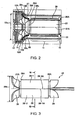
Fig. 2 is a sectional view showing chief parts of the power tool according to the embodiment; -
Fig. 3 is a side view showing a stator of a motor of the power tool in a state where a fan wind guide is not provided; -
Fig. 4 is a plan view showing the stator; -
Fig. 5 is a front view showing the stator; -
Fig. 6 is a rear view showing the stator; -
Fig. 7 is a sectional view taken along the line VII-VII ofFig. 3 ; -
Fig. 8 is a side view showing the stator; -
Fig. 9 is a partial sectional view showing a power tool according to a first modification of the embodiment; -
Fig. 10 is a sectional view showing chief parts of the power tool according to the first modification of the embodiment; -
Fig. 11 is a partial sectional view showing a power tool according to a second modification of the embodiment; -
Fig. 12 is a sectional view showing chief parts of the power tool according to a second modification of the embodiment; -
Fig. 13 is a partial sectional view showing a conventional power tool; and -
Fig. 14 is a sectional view showing chief parts of the conventional power tool. - A power tool according to an embodiment of the invention will be described with reference to
Figs. 1 to 8 . The power tool 1 is more specifically a disc grinder, and as shown inFig. 1 , mainly includes ahousing 10 in which amotor 20 having arotor 21, astator 25 and acommutator 35 is housed and fixed, agrindstone 71 provided at a front end of thehousing 10, afan 12, atail cover 40 having a power switch (not shown) and fixed to a rear end of thehousing 10. - The inside of the
housing 10 and the inside of thetail cover 40 communicates with each other, and thetail cover 40 is formed with anair inlet 40a which allow the inside of thetail cover 40 and the inside of thehousing 10 to communicate with the atmosphere. Thehousing 10 has a statorcore facing portion 11 is positioned to face astator core 26 in a direction perpendicular to a rotational axis direction of therotor 21. Agear cover 60 is fixed to and provided at front end of thehousing 10, and thegear cover 60 is formed with afan wind outlet 60a which allows the atmosphere and the inside of thehousing 10 to communicate with each other, and allows fan wind to be discharged therethrough. Anoutput shaft 20A of themotor 20 is adapted to be rotatable coaxially and integrally with the rotational axis of therotor 21, and extends into thegear cover 60. Agear 61 which is coaxially and integrally rotatable with theoutput shaft 20A is provided in the vicinity of a tip of the output shaft. Theoutput shaft 20A (rotational axis of the rotor 21) of themotor 20 coincides with the position of anaxis 21A of astator core 26. - A
gear 62 which is fixed to arotary shaft 63 rotatably supported within thegear cover 60 and which is rotatable coaxially and integrally with therotary shaft 63 meshes with thegear 61, and a substantially disc-like grindstone 71 is coaxially attached to a lower end of therotary shaft 63 shown inFig. 1 so as to rotate integrally therewith. By this configuration, as therotor 21 of themotor 20 rotates, thegrindstone 71 is adapted to rotate. - The
fan 12 is fixed to a portion of theoutput shaft 20A of themotor 20, i.e., a portion in the vicinity of thegear cover 60 within thehousing 10, and is adapted to rotate coaxially and integrally with theoutput shaft 20A of themotor 20 as therotor 21 rotates. Thefan 12 includes a centrifugal fan having a plurality ofblades 12A. The peripheral edge portions of theblades 12A form an imaginary rotational contour having a range where thefan 12 which rotates moves in a space as thefan 12 rotates. The external shape of the rotational contour is defined by an imaginary rotational contour surface, and the portion of the rotational contour surface which faces themotor 20 forms an end surface of the rotational contour surface which faces a fan-sidecoil end portion 28. The portion of theblade 12A which forms the end surface of the rotational contour surface, as shown inFig. 2 , has aninclined portion 12B which is inclined to form a given angle with respect to the rotational axis direction of therotor 21, i.e., to the axial direction of thestator core 26. By theinclined portion 12B, the end surface of the rotational contour surface forms an inclined surface which is inclined to form a given angle with respect to the rotational axis direction of therotor 21. Thefan 12, as shown inFig. 2 , has a bladeexternal diameter 12a with the rotational axis of therotor 21 as a center. - The centrifugal fan discharges air radially outward of the centrifugal fan by the centrifugal force by the rotation of the centrifugal fan. The
fan 12 includes such a centrifugal fan. Therefore, as the gap between the end surface of the rotational contour surface and the fan-sidecoil end portion 28 becomes small, i.e., as the distance between theinclined portion 12B of theblade 12A and the fan facing portion 28c of the fan-sidecoil end portion 28 becomes small, the cooling wind which cools the fan-sidecoil end portion 28 increases. The air which has flowed in from theair inlet 40a passes through thestator 25, flows to the peripheral edge portion of thefan 12 from the position of the axis of thefan 12 and its vicinity, and is discharged to the atmosphere from thefan wind outlet 60a. Since thefan 12 includes the centrifugal fan, the air flow around the rotational axis of thefan 12 and the position which faces its vicinity can be increased, the cooling efficiency for astator coil bundle 27 can be raised, and a power tool 1 with higher output can be obtained. - The
stator 25 includes a substantiallycylindrical stator core 26 having a length of about 45 to 60 mm in a right-and-left direction ofFig. 2 that is the axial direction and having a maximumexternal diameter 26a (Fig. 4 ). Thestator core 26 has two magnetic poles, and as shown inFig. 2 , has magnetic pole ends 26A respectively provided at portions of the magnetic poles, i.e., in positions corresponding to axial ends of thestator core 26. As shown inFig. 7 ,slots 26b which extend in a circumferential direction are formed in the vicinity of the magnetic pole ends 26A, and the stator coil bundles 27 including bundles of magnetic wires are respectively installed within theslots 26b. Eachstator coil bundle 27 has the fan-sidecoil end portion 28 which protrudes substantially axially of thestator core 26 from themagnetic pole end 26A corresponding to one end that is a left end (Fig. 2 ) of thestator core 26, and a commutator-side coil end portion 29 (Fig. 1 ) which protrudes axially of thestator core 26 from themagnetic pole end 26A corresponding to the other end that is a right end (Fig. 2 ) of thestator core 26. - As shown in
Figs. 5 to 7 , thestator core 26 is adapted to be capable of being split into a pair of stator core portions 26-1 and 26-2. Split surfaces 26-1A and 26-2A of thestator core 26 are arranged on the way of a magnetic path which connects two magnetic poles of thestator 25. One of the split surfaces 26-1A and 26-2A of the stator core is ridge-shaped, and the other thereof is valley-shaped, and the ridge-shaped and valley-shaped split surfaces 26-1A and 26-2A positioned to be respectively parallel to the rotational axis of the rotor 21 (Fig. 1 ) which coincides with theoutput shaft 20A of themotor 20. After magnetic wires supplied from nozzles of a winding machine (not shown) are respectively wound around the stator core portions 26-1 and 26-2 and made into the stator coil bundles 27 such that the stator coil bundles 27 are installed within theslots 26b of the stator core portions 26-1 and 26-2, as shown inFigs. 5 to 7 , the ridge-shaped and valley-shaped stator core split surfaces 26-1A and 26-2A which are split into two pieces are combined together so as to abut on each other, thereby forming the substantiallycylindrical stator core 26. In this state, thestator core 26 is installed in thehousing 10. - Since the
stator core 26 is adapted to be capable of being split as such, when magnetic wires are wound and made into the stator coil bundles 27, limitation of winding positions of the magnetic wires resulting from the size of the nozzles of the winding machine used to supply the magnetic wires can be reduced, and the magnetic wires can be wound around thestator core 26 such that the stator coil bundles 27 are arranged in theslots 26b, respectively, until awidth 27a (Figs. 5 to 7 ) between thestator coil bundle 27 on the side of one pole and thestator coil bundle 27 on the side of the other pole within thestator core 26 becomes 3 mm or less. For this reason, as shown inFig. 7 , acoil cross-section length 27b (Fig. 7 ) of thestator core 26 in the circumferential direction can be set to 15 mm to 20 mm, and can be set to be significantly large values compared with a coil cross-section length of 8 mm to 14 mm of a conventional power tool. As a result, the stator coil bundles 27 having significantly larger cooling area than the conventional power tool can be obtained, the surface area of thecoil end portions - As mentioned above, the
housing 10 has the statorcore facing portion 11 positioned to face thestator core 26 in the direction perpendicular to the rotational axis direction of therotor 21, the fan-sidecoil end portion 28 and the statorcore facing portion 11 are positioned to face each other in the rotational axis direction of therotor 21, and the statorcore facing portion 11 forms an grip portion of a disc grinder that is the power tool 1. For this reason, the external diameter of a casing in the statorcore facing portion 11 can be made small, the air that is cooling wind can be easily made to flow along the fan-sidecoil end portion 28, and the cooling efficiency in thestator 25 can be improved. The internal diameter of the fan facing portion 28c having the rotational axis of therotor 21 as a center can be made small to a value approximate to the maximumexternal diameter 26a (Fig. 4 ) of thestator core 26, and a small-sized power tool 1 with high output can be obtained. Since the statorcore facing portion 11 forms the grip portion of the disc grinder, the power tool 1 in which the external diameter of the grip portion is set to a moderate size can be obtained, and a disc grinder as the power tool 1 which can facilitate gripping and can improve the working efficiency can be obtained. - The whole
stator coil bundle 27 is molded of heat-curable resin, and accordingly, the fan-sidecoil end portion 28 and the commutator-sidecoil end portion 29 are also molded. The fan-sidecoil end portion 28 and the commutator-sidecoil end portion 29 are thin plate-shaped. More specifically, the commutator-sidecoil end portion 29, as shown inFig. 3 , is formed in such a shape that portions of a substantially cylindrical shape, i.e., portions corresponding to the vicinities of imaginary extending lines of the stator core split surfaces 26-1A and 26-2A are cut out, and the upper side ofFig. 3 forms one pole side, and the lower side thereof forms the other pole side. - The portion of the fan-side
coil end portion 28 in the vicinity of themagnetic pole end 26A of the left end (shown inFig. 3 ) of thestator core 26, as shown inFig. 3 , is formed in such a shape that portions of a substantially cylindrical shape, i.e., portions corresponding to the vicinities of imaginary extending lines of the stator core split surfaces 26-1A and 26-2A are cut out. Also, the fan-sidecoil end portion 28 is gradually separated from the axis of thestator core 26 toward an extending end of the fan-sidecoil end portion 28 located at a left end ofFig. 3 , is formed in a shape that is directed to a direction along theinclined portion 12B of theblade 12A of thefan 12 as shown inFig. 2 , and is formed in such a shape that its diameter is increased with the axis of thestator core 26 as a center toward a tip of the fan-sidecoil end portion 28 like a tip portion of a horn or morning glory. The upper side (Fig. 3 ) of the fan-sidecoil end portion 28 forms one pole side, and the lower side thereof forms the other pole side. - As such, since the fan-side
coil end portion 28 is formed such a shape such that its diameter is increased toward an extending end, the coil end portion has a minimuminternal diameter 28a (Fig. 2 ) with the axis of thestator core 26 as a center in a position in the vicinity of one end of thestator core 26, and has a maximumexternal diameter 28b (Fig. 2 ) in the position of the extending end. The minimuminternal diameter 28a is smaller than a bladeexternal diameter 12a of thefan 12 mentioned above, and is greater than or equal to the maximumexternal diameter 26a (Fig. 4 ) of thestator core 26 mentioned above. For this reason, the fan-sidecoil end portion 28 can be sufficiently made to face thefan 12, the cooling area of the fan-sidecoil end portion 28 can be increased, and a configuration in which the fan-sidecoil end portion 28 can be sufficiently cooled by the air flow by thefan 12 can be obtained. - The fan-side
coil end portion 28, as shown inFig. 2 , has the fan facing portion 28c which faces thefan 12 in the direction perpendicular to the rotational axis of therotor 21. That is, the portion of thefan 12 which faces one end of thestator core 26, i.e., a portion of the rotational contour which faces the fan-sidecoil end portion 28 is arranged within a space surrounded by the fan-sidecoil end portion 28. For this reason, the fan-sidecoil end portion 28 and theinclined portion 12B of theblade 12A of thefan 12 are arranged to face each other via a narrow gap of about 2 mm in the axial direction of therotor 21. In more detail, the fan facing portion 28c is formed in a shape that it extends with a gap of about 0.5 to 2 mm being kept between the fan facing portion and theinclined portion 12B of theblade 12A. - The length of the fan facing portion 28c in the extension direction of the fan-side
coil end portion 28 shown inFig. 2 is about 3 to 7 mm. In case of a conventional power tool, it was necessary to lengthen thehousing 10 in the axial direction of therotor 21 by 3 to 7 mm that is the length of the fan facing portion 28c. However, since the housing is curved as shown inFig. 2 in this embodiment, it is possible to dispense with lengthening thehousing 10 in the axial direction of thestator core 26 in this way, and the power tool 1 can be made small. Since the fan facing portion 28c is arranged as close as about 2 mm in the axial direction of therotor 21 from theblade 12A where the air that is cooling wind turns the greatest, the cooling efficiency of thestator 25 having the fan-sidecoil end portion 28 can be improved significantly. Across-section 28d of the fan-sidecoil end portion 28 in the extension direction of the fan-sidecoil end portion 28 shown inFig. 2 has a length of about 15 mm to 20 mm in the extension direction, and a thickness of about 2 mm to 5 mm, and is formed in a flat shape compared with general coil end portion dimensions (a length of 8 mm to 114 mm and a thickness of about 5 mm to 10 mm), and the fan-sidecoil end portion 28 of this embodiment has a structure in which cooling surface area is very broad. - Moreover, since the fan facing portion 28c extends toward a protruding end of the fan-side
coil end portion 28 along the end surface of the rotational contour surface of thefan 12, i.e., along theinclined portion 12B of theblade 12A of thefan 12, the cooling area of the fan-sidecoil end portion 28 can be further increased without increasing the number of parts, the cooling efficiency can be further raised, and the power tool 1 with higher output can be obtained. Thefan 12 can be brought closer to the fan-sidecoil end portion 28, and the power tool 1 can be made smaller in the rotational axis direction of therotor 21. The fan-sidecoil end portion 28 is functioning as a fan guide which increases the air flow around the rotational axis of thefan 12, thereby increasing cooling wind. - Since the fan-side
coil end portion 28 is resin-molded, the rigidity of the fan-sidecoil end portion 28 can be improved. The fan-sidecoil end portion 28 can be formed with high dimensional precision. For this reason, even in the power tool 1 with large vibration, there is no case that therotor 21 and thecoil end portions coil end portion 28 and commutator-sidecoil end portion 29 which are thinner and sufficiently broad in cooling area can be obtained, the cooling efficiency can be further raised, and the power tool 1 with higher output can be obtained. - As shown in
Fig. 8 , there is a case that a fanwind guide portion 30 made of resin constituting a resin mold is fixed to the fan-sidecoil end portion 28 by adhesion. The fan-sidecoil end portion 28 is formed in such a shape that portions of a substantially cylindrical shape, i.e., portions corresponding to the vicinities of imaginary extending lines of the stator core split surfaces 26-1A and 26-2A are cut out as earlier mentioned. However, the fanwind guide portion 30 extends from the fan-sidecoil end portion 28 so as to bury the cutout portion, and connects the fan-sidecoil end portion 28 on the side of one pole and the other fan-sidecoil end portion 28, the fan-sidecoil end portion 28 and the fanwind guide portion 30 are formed in a shape like a tip portion of a horn or morning glory, and the tip (left end ofFig. 8 ) of the fan-sidecoil end portion 28 is formed in a substantially annular shape with the rotational axis of therotor 21 as a center. Since the fanwind guide portion 30 is provided, the amount of wind which flows along thefan 12 can be increased, the cooling efficiency can be further raised, and the power tool 1 with higher output can be obtained. Additionally, the discharge of air that is cooling wind of thefan 12 becomes smooth, and fan noises can be reduced. - As shown in
Fig. 2 , afan guide 31 which is connected to the tip of the fan-sidecoil end portion 28 and extends toward thehousing 10 is provided. Thenfan guide 31 extends from the tip of the fan-sidecoil end portion 28 in the extension direction of the fan-sidecoil end portion 28, leads to an inner peripheral surface of thehousing 10, and extends in a left direction ofFig. 2 along the inner peripheral surface of thehousing 10, as shown inFig. 2 , from that portion, thereby surrounding the surroundings of the fan. - The power tool according to the invention is not limited to the above-described embodiment, and various modifications or improvements can be made within the scope defined in the claims. For example, a guide portion which is arranged so as to cover a space between an extending end of a coil end portion and a peripheral edge portion of the
fan 12 may be provided. In this case, as shown inFigs. 9 and10 , aguide portion 131 may be provided so as to cover a portion of theinclined portion 12B of thefan 12, i.e., a space between a peripheral edge portion of the end surface of the rotational contour surface and an extending end of the fan-sidecoil end portion 28 having the rotational axis of therotor 21 as a center. By providing theguide portion 131 in this way, the air flow around the rotational axis of thefan 12 can be increased, the cooling efficiency can be further raised, and apower tool 101 with higher output can be obtained. - The fan-side
coil end portion 28 has a dimension of about 15 mm to 20 mm in its extension direction, and is significantly large compared with a dimension of about 8 mm to 14 mm in a conventional power tool. However, as described in this embodiment, the fan-side coil end portion extends so as to roll back in a direction apart from the rotational axis of therotor 21, theguide portion 131 can be housed in the space between thehousing 10 and the fan-sidecoil end portion 28. Therefore, while the cooling surface area of the fan-sidecoil end portion 28 improves, the dimensions in the rotational axis direction of therotor 21 are not different from the conventional power tool. Moreover, when dust such as gravels can be sucked in fromair inlet 40a during the operation of thepower tool 101, the dust is bounced by theblade 12A which rotates in thefan 12. In this case, theguide portion 131 protects the fan-sidecoil end portion 28, and prevents the dust from colliding against the fan-sidecoil end portion 28. As a result, thepower tool 101 with long life span can be obtained. - In addition to the above-described modification, the shape of the fan-side coil end portion 28 (stator coil bundle 27) may be changed from this embodiment. For example, as shown in
Figs. 11 and12 , a portion ranging from a base of the fan-sidecoil end portion 128 in the vicinity of thestator core 26 to a coil curved portion 128e in a cross-section 128d of the fan-sidecoil end portion 128 is parallel to the rotational axis direction (direction of theaxis 21A of the stator core 26) of therotor 21, and a portion ranging from the coil curved portion 128e to an extending end of the fan-sidecoil end portion 128 extends perpendicularly to the rotational axis direction (direction of theaxis 21A of the stator core 26) of therotor 21 to apart from the rotational axis of therotor 21. By adopting this configuration, the fan-side coil end portion 128 (stator coil bundle 127) can be made to largely extend in the direction apart from the rotational axis of therotor 21, and apower tool 201 can be made small in the direction of theaxis 21A of thestator core 26. - In this embodiment, the fan
wind guide portion 30 which is made of resin constituting a resin mold of the fan-sidecoil end portion 28 and extends from the fan-sidecoil end portion 28 is fixed to the fan-sidecoil end portion 28 by adhesion. Instead of this, a fan wind guide portion which is formed integrally with the resin mold of the fan-sidecoil end portion 28 can be provided. - Although a two-pole commutator motor using two stator coils has been described in this embodiment, the invention is not limited thereto, and the invention can also be applied to a commutator motor having two or more stator coils.
- According to the invention, it is possible to provide a power tool which can prevent dimensions from increasing, raise the cooling efficiency in the coil end portion, and suppress an increase in manufacturing cost.
Claims (15)
- A power tool comprising:a commutator motor including a rotor and a stator having a substantially cylindrical stator core;a fan that is provided to face one axial end of the stator core, that has a plurality of blades and that is rotatable coaxially with the rotor; anda stator coil bundle that includes a bundle of magnetic wires and that is fixed to an inner peripheral surface of the stator core, the stator coil bundle having a coil end portion that protrudes more than the one end of the stator core in a rotational axis direction of the rotor, characterized in that:with respect to the rotational axis direction, a minimum internal diameter of the coil end portion is smaller than a maximum external diameter of the fan; andthe coil end portion has a fan facing portion that faces the fan along a direction perpendicular to the rotational axis direction.
- The power tool according to Claim 1,
wherein a rotational contour that faces the coil end portion is formed in accordance with a rotation of the fan, and
wherein the fan facing portion outwardly extends along the rotational contour. - The power tool according to Claim 2,
wherein each of the blades has an inclined portion at which the rotational contour is inclined with respect to the rotational axis direction, and
wherein the fan facing portion extends along the inclined portion. - The power tool according to Claim 1,
wherein the stator core is formed of a plurality of split cores that are splittable from each other at split surfaces parallel to the rotational axis direction. - The power tool according to Claim 1,
wherein the fan includes a centrifugal fan. - The power tool according to Claim 1,
wherein at least the coil end portion of the stator coil bundle is resin-molded. - The power tool according to Claim 6,
wherein a fan wind guide portion is provided to extend from the coil end portion so as to increase an air flow amount therearound. - The power tool according to Claim 1,
wherein a guide portion is provided to cover a space between an extending end of the coil end portion and a peripheral edge portion of the fan. - The power tool according to Claim 1,
wherein a housing in which the commutator motor is fixedly housed is provided,
wherein the housing has a stator core facing portion that is positioned to face the stator core in a direction perpendicular to the rotational axis direction, and
wherein the coil end portion and the stator core facing portion are positioned to face each other along the rotational axis direction. - The power tool according to Claim 9,
wherein at least a portion of the stator core facing portion forms a grip portion. - The power tool according to Claim 1,
wherein the power tool is a disc grinder. - A power tool comprising:a commutator motor including a rotor and a stator having a substantially cylindrical stator core;a fan that is provided to face one axial end of the stator core, that has a plurality of blades and that is rotatable coaxially with the rotor; anda stator coil bundle that includes a bundle of magnetic wires and that is fixed to an inner peripheral surface of the stator core, the stator coil bundle having a coil end portion that protrudes more than the one end of the stator core in a rotational axis direction of the rotor, characterized in that:the coil end portion is substantially plate-shaped; andthe coil end portion is formed so that an internal diameter thereof with respect to the rotational axis direction increases from a base portion that is positioned in the vicinity of the stator core toward a protruding end portion.
- A power tool comprising:a commutator motor including a rotor and a stator having a substantially cylindrical stator core;a fan that is provided to face one axial end of the stator core, that has a plurality of blades and that is rotatable coaxially with the rotor; anda stator coil bundle that includes a bundle of magnetic wires and that is fixed to an inner peripheral surface of the stator core, the stator coil bundle having a coil end portion that protrudes more than the one end of the stator core in a rotational axis direction of the rotor, characterized in that:the fan includes a centrifugal fan;with respect to the rotational axis direction, a maximum external diameter of the coil end portion is greater than or equal to a maximum external diameter of the stator core; andthe coil end portion forms a fan guide that defines a air flow path toward the centrifugal fan.
- A power tool comprising:a commutator motor including a rotor and a stator having a substantially cylindrical stator core;a fan that is provided to face one axial end of the stator core, that has a plurality of blades and that is rotatable coaxially with the rotor; anda stator coil bundle that includes a bundle of magnetic wires and that is fixed to an inner peripheral surface of the stator core, the stator coil bundle having a coil end portion that protrudes more than the one end of the stator core in a rotational axis direction of the rotor, characterized in that:at least the coil end portion of the stator coil bundle is resin-molded; andthe coil end portion is formed so that an internal diameter thereof with respect to the rotational axis direction increases from a base portion that is positioned in the vicinity of the stator core toward a protruding end portion.
- The power tool according to Claim 14,
wherein a fan wind guide portion is provided to extend from the coil end portion so as to increase an air flow amount therearound.
Applications Claiming Priority (1)
| Application Number | Priority Date | Filing Date | Title |
|---|---|---|---|
| JP2008005963A JP5019126B2 (en) | 2008-01-15 | 2008-01-15 | Electric tool |
Publications (2)
| Publication Number | Publication Date |
|---|---|
| EP2081283A2 true EP2081283A2 (en) | 2009-07-22 |
| EP2081283A3 EP2081283A3 (en) | 2014-12-17 |
Family
ID=40585579
Family Applications (1)
| Application Number | Title | Priority Date | Filing Date |
|---|---|---|---|
| EP09000309.6A Withdrawn EP2081283A3 (en) | 2008-01-15 | 2009-01-12 | Power tool |
Country Status (4)
| Country | Link |
|---|---|
| US (1) | US8338994B2 (en) |
| EP (1) | EP2081283A3 (en) |
| JP (1) | JP5019126B2 (en) |
| CN (1) | CN101488681A (en) |
Cited By (1)
| Publication number | Priority date | Publication date | Assignee | Title |
|---|---|---|---|---|
| CN102710080A (en) * | 2012-04-16 | 2012-10-03 | 东莞市高创电机科技有限公司 | A high-flow high-voltage DC motor and its assembly process |
Families Citing this family (20)
| Publication number | Priority date | Publication date | Assignee | Title |
|---|---|---|---|---|
| CN102111037B (en) * | 2009-12-29 | 2014-09-03 | 德昌电机(深圳)有限公司 | Motor |
| KR101218202B1 (en) * | 2010-04-01 | 2013-01-04 | 제이아이산업(주) | The air discharge structure of an air grinder |
| JP2012035339A (en) * | 2010-08-03 | 2012-02-23 | Hitachi Koki Co Ltd | Electric tool |
| US20130333228A1 (en) * | 2011-02-28 | 2013-12-19 | Makita Corporation | Cutting tool |
| JP5705648B2 (en) * | 2011-05-23 | 2015-04-22 | 株式会社マキタ | Electric tool |
| JP5826526B2 (en) * | 2011-06-08 | 2015-12-02 | 株式会社マキタ | Electric tool |
| JP5722156B2 (en) * | 2011-08-02 | 2015-05-20 | 株式会社マキタ | Electric tool |
| JP5725354B2 (en) * | 2011-08-19 | 2015-05-27 | 日立工機株式会社 | Electric tool |
| US9289878B2 (en) * | 2013-08-30 | 2016-03-22 | Ingersoll-Rand Company | Grinders with friction drives |
| DE212015000120U1 (en) * | 2014-05-30 | 2016-12-16 | Hitachi Koki Co., Ltd. | Electric tool |
| US9475172B2 (en) | 2014-07-15 | 2016-10-25 | Milwaukee Electric Tool Corporation | Adjustable guard for power tool |
| TWI584561B (en) * | 2015-02-13 | 2017-05-21 | 周文三 | Motor with heat dissipation structure |
| JP6455226B2 (en) * | 2015-02-27 | 2019-01-23 | 工機ホールディングス株式会社 | Electric working machine |
| CN107030608B (en) * | 2016-02-04 | 2019-08-06 | 南京德朔实业有限公司 | sander |
| CN107546885A (en) * | 2016-06-28 | 2018-01-05 | 德昌电机(深圳)有限公司 | Rotor, the manufacture method of rotor, motor and electric tool |
| CN117498640A (en) * | 2018-02-13 | 2024-02-02 | 苏州宝时得电动工具有限公司 | Hand-held electric tool |
| US12011818B2 (en) * | 2018-06-29 | 2024-06-18 | Koki Holdings Co., Ltd. | Electric tool |
| JP7260394B2 (en) * | 2019-05-21 | 2023-04-18 | ファナック株式会社 | stator |
| USD1112374S1 (en) | 2021-07-30 | 2026-02-10 | Techtronic Cordless Gp | Handheld cultivator |
| CN117967586A (en) * | 2022-10-25 | 2024-05-03 | 苏州宝时得电动工具有限公司 | Centrifugal fans, external rotor motors and power tools |
Citations (2)
| Publication number | Priority date | Publication date | Assignee | Title |
|---|---|---|---|---|
| JP3687479B2 (en) | 2000-04-07 | 2005-08-24 | 日立工機株式会社 | Commutator motor stator |
| JP2008005963A (en) | 2006-06-28 | 2008-01-17 | Fuji Seal International Inc | Medical container with rfid |
Family Cites Families (28)
| Publication number | Priority date | Publication date | Assignee | Title |
|---|---|---|---|---|
| US1229401A (en) * | 1916-03-23 | 1917-06-12 | Samuel D Black | Drill-gearing. |
| US2048096A (en) * | 1935-07-17 | 1936-07-21 | Chicago Flexible Shaft Co | Electric motor |
| US2103922A (en) * | 1935-09-19 | 1937-12-28 | Gen Electric | Mixing device |
| US2539003A (en) * | 1946-05-03 | 1951-01-23 | Agustoni Romeo | Portable machine tool |
| US2512905A (en) * | 1948-12-30 | 1950-06-27 | Gen Electric | Baffle and end shield assembly for dynamoelectric machines |
| US3194993A (en) * | 1960-10-03 | 1965-07-13 | Allis Chalmers Mfg Co | Encapsulated dynamoelectric machines |
| US3121813A (en) * | 1960-11-15 | 1964-02-18 | Millers Falls Co | Electric power unit |
| US3873862A (en) * | 1970-05-13 | 1975-03-25 | Murphy Ind Inc G W | Rotary saw |
| US3725706A (en) * | 1971-07-26 | 1973-04-03 | Gen Electric | Heat transfer system for dynamoelectric machine |
| JPS56115154A (en) * | 1980-02-13 | 1981-09-10 | Taihei Denki Seisakusho:Kk | Coil of electric rotary machine |
| JPS576546A (en) * | 1980-06-11 | 1982-01-13 | Hitachi Ltd | Resin molded motor |
| JPS6134849Y2 (en) * | 1980-07-15 | 1986-10-09 | ||
| US4670677A (en) * | 1986-04-25 | 1987-06-02 | Emerson Electric Co. | Electric motor with shrouded fan |
| ES2041930T3 (en) | 1988-10-11 | 1993-12-01 | Schorch Gmbh | AN ELECTRIC MOTOR. |
| DE3923421A1 (en) * | 1989-07-15 | 1991-01-24 | Kress Elektrik Gmbh & Co | UNIVERSAL ELECTRIC MOTOR |
| US5387087A (en) * | 1994-03-28 | 1995-02-07 | Chen; Li-Mei | Fan capable of directing air flow in both axial and radial directions |
| JPH10136611A (en) * | 1996-11-01 | 1998-05-22 | Hitachi Koki Co Ltd | Electric tool |
| US6411000B1 (en) * | 1999-11-02 | 2002-06-25 | Lg Electronics Inc. | Motor with a cooling means |
| JP2002154042A (en) * | 2000-11-17 | 2002-05-28 | Nidec Shibaura Corp | Hand-held disk grinder |
| US7036207B2 (en) * | 2001-03-02 | 2006-05-02 | Encap Motor Corporation | Stator assembly made from a plurality of toroidal core segments and motor using same |
| JP3800084B2 (en) * | 2001-12-14 | 2006-07-19 | 日立工機株式会社 | Electric tool |
| DE10261572A1 (en) * | 2002-12-23 | 2004-07-01 | Robert Bosch Gmbh | Electric hand tool machine e.g. drill, has arrangement for generating additional cooling air flow that passes at least one machine component outside or in low flow region of cooling air flow |
| JP4557555B2 (en) * | 2004-01-08 | 2010-10-06 | 株式会社マキタ | Electric tool |
| JP4466098B2 (en) * | 2004-02-03 | 2010-05-26 | 日立工機株式会社 | Electric motor, electric tool including the same, and method for manufacturing electric motor |
| JP4533016B2 (en) * | 2004-06-16 | 2010-08-25 | 日立工機株式会社 | Electric tools and stators for electric tools |
| JP4595442B2 (en) | 2004-08-24 | 2010-12-08 | 日立工機株式会社 | Electric motor, electric tool including the same, and method for manufacturing electric motor |
| JP4412166B2 (en) * | 2004-12-15 | 2010-02-10 | 日立工機株式会社 | Electric motor and electric tool including the same |
| US8084900B2 (en) * | 2008-08-20 | 2011-12-27 | Robert Bosch Gmbh | Asymmetrical stator of an electrical machine |
-
2008
- 2008-01-15 JP JP2008005963A patent/JP5019126B2/en not_active Expired - Fee Related
-
2009
- 2009-01-09 US US12/351,155 patent/US8338994B2/en not_active Expired - Fee Related
- 2009-01-12 EP EP09000309.6A patent/EP2081283A3/en not_active Withdrawn
- 2009-01-12 CN CNA2009100015754A patent/CN101488681A/en active Pending
Patent Citations (2)
| Publication number | Priority date | Publication date | Assignee | Title |
|---|---|---|---|---|
| JP3687479B2 (en) | 2000-04-07 | 2005-08-24 | 日立工機株式会社 | Commutator motor stator |
| JP2008005963A (en) | 2006-06-28 | 2008-01-17 | Fuji Seal International Inc | Medical container with rfid |
Cited By (1)
| Publication number | Priority date | Publication date | Assignee | Title |
|---|---|---|---|---|
| CN102710080A (en) * | 2012-04-16 | 2012-10-03 | 东莞市高创电机科技有限公司 | A high-flow high-voltage DC motor and its assembly process |
Also Published As
| Publication number | Publication date |
|---|---|
| US8338994B2 (en) | 2012-12-25 |
| US20090179507A1 (en) | 2009-07-16 |
| EP2081283A3 (en) | 2014-12-17 |
| JP5019126B2 (en) | 2012-09-05 |
| CN101488681A (en) | 2009-07-22 |
| JP2009171717A (en) | 2009-07-30 |
Similar Documents
| Publication | Publication Date | Title |
|---|---|---|
| US8338994B2 (en) | Power tool | |
| CN110653699B (en) | Angle grinder and electric tool | |
| RU2508977C2 (en) | Processing machine driven by motor | |
| US7166939B2 (en) | Electric hand tool | |
| CN105307821A (en) | electrical tools | |
| US7605513B2 (en) | Electric tool having electric motor with first and second coils having first and second coil bundles of different innermost peripheral length | |
| JP4407158B2 (en) | Portable power tools | |
| EP2319163B1 (en) | Power tool with motor air flow path control | |
| EP1367692B1 (en) | Stator structure for a rotation detector | |
| CN212343445U (en) | Brushless external rotor motor | |
| CN100442641C (en) | Electric motor and electric tool with the same | |
| US7777372B2 (en) | Electric motor, electric tool having the motor, and electric motor production method | |
| JP4635563B2 (en) | Electric blower | |
| JP5257658B2 (en) | Commutator motor armature and electric tool including the same | |
| CN101263643A (en) | Electric motors and electric tools with electric motors | |
| JP5218819B2 (en) | Electric tool | |
| CN112117840A (en) | Brushless external rotor motor | |
| JP4533016B2 (en) | Electric tools and stators for electric tools | |
| JP2010017056A (en) | Power tool | |
| CN118739653A (en) | Aerodynamically optimized rotor for electric drives | |
| US20060097602A1 (en) | Electric motor and electric tool having the motor | |
| JP2010081744A (en) | Power tool | |
| JP3800084B2 (en) | Electric tool | |
| JP2007028743A (en) | Commutator motor rotor and electric tool including the same | |
| CN107437860B (en) | Rotary electric machines provided with winding heads |
Legal Events
| Date | Code | Title | Description |
|---|---|---|---|
| PUAI | Public reference made under article 153(3) epc to a published international application that has entered the european phase |
Free format text: ORIGINAL CODE: 0009012 |
|
| AK | Designated contracting states |
Kind code of ref document: A2 Designated state(s): AT BE BG CH CY CZ DE DK EE ES FI FR GB GR HR HU IE IS IT LI LT LU LV MC MK MT NL NO PL PT RO SE SI SK TR |
|
| AX | Request for extension of the european patent |
Extension state: AL BA RS |
|
| 17P | Request for examination filed |
Effective date: 20090904 |
|
| RIC1 | Information provided on ipc code assigned before grant |
Ipc: H02K 9/06 20060101ALI20140724BHEP Ipc: H02K 7/14 20060101AFI20140724BHEP |
|
| PUAL | Search report despatched |
Free format text: ORIGINAL CODE: 0009013 |
|
| AK | Designated contracting states |
Kind code of ref document: A3 Designated state(s): AT BE BG CH CY CZ DE DK EE ES FI FR GB GR HR HU IE IS IT LI LT LU LV MC MK MT NL NO PL PT RO SE SI SK TR |
|
| AX | Request for extension of the european patent |
Extension state: AL BA RS |
|
| RIC1 | Information provided on ipc code assigned before grant |
Ipc: H02K 9/06 20060101ALI20141113BHEP Ipc: H02K 7/14 20060101AFI20141113BHEP |
|
| AKX | Designation fees paid |
Designated state(s): AT BE BG CH CY CZ DE DK EE ES FI FR GB GR HR HU IE IS IT LI LT LU LV MC MK MT NL NO PL PT RO SE SI SK TR |
|
| AXX | Extension fees paid |
Extension state: AL Extension state: BA Extension state: RS |
|
| STAA | Information on the status of an ep patent application or granted ep patent |
Free format text: STATUS: THE APPLICATION IS DEEMED TO BE WITHDRAWN |
|
| 18D | Application deemed to be withdrawn |
Effective date: 20150618 |