EP2081196A2 - Wire cable for saving energy - Google Patents
Wire cable for saving energy Download PDFInfo
- Publication number
- EP2081196A2 EP2081196A2 EP09150320A EP09150320A EP2081196A2 EP 2081196 A2 EP2081196 A2 EP 2081196A2 EP 09150320 A EP09150320 A EP 09150320A EP 09150320 A EP09150320 A EP 09150320A EP 2081196 A2 EP2081196 A2 EP 2081196A2
- Authority
- EP
- European Patent Office
- Prior art keywords
- wire
- conductors
- saving energy
- wire cable
- electric conductor
- Prior art date
- Legal status (The legal status is an assumption and is not a legal conclusion. Google has not performed a legal analysis and makes no representation as to the accuracy of the status listed.)
- Withdrawn
Links
- 239000004020 conductor Substances 0.000 claims abstract description 91
- 239000012212 insulator Substances 0.000 claims abstract description 10
- 229910045601 alloy Inorganic materials 0.000 claims abstract description 4
- 239000000956 alloy Substances 0.000 claims abstract description 4
- RYGMFSIKBFXOCR-UHFFFAOYSA-N Copper Chemical compound [Cu] RYGMFSIKBFXOCR-UHFFFAOYSA-N 0.000 claims description 12
- 229910052802 copper Inorganic materials 0.000 claims description 9
- 239000010949 copper Substances 0.000 claims description 9
- PNEYBMLMFCGWSK-UHFFFAOYSA-N aluminium oxide Inorganic materials [O-2].[O-2].[O-2].[Al+3].[Al+3] PNEYBMLMFCGWSK-UHFFFAOYSA-N 0.000 claims description 7
- 238000003466 welding Methods 0.000 claims description 2
- 230000006835 compression Effects 0.000 claims 1
- 238000007906 compression Methods 0.000 claims 1
- 229910052751 metal Inorganic materials 0.000 abstract description 25
- 239000002184 metal Substances 0.000 abstract description 25
- 150000002739 metals Chemical class 0.000 abstract description 6
- 230000008901 benefit Effects 0.000 description 8
- 230000005611 electricity Effects 0.000 description 7
- 239000010410 layer Substances 0.000 description 6
- 230000000694 effects Effects 0.000 description 5
- 229910052782 aluminium Inorganic materials 0.000 description 4
- XAGFODPZIPBFFR-UHFFFAOYSA-N aluminium Chemical compound [Al] XAGFODPZIPBFFR-UHFFFAOYSA-N 0.000 description 4
- 239000000463 material Substances 0.000 description 4
- 230000003247 decreasing effect Effects 0.000 description 3
- 230000002500 effect on skin Effects 0.000 description 3
- 230000001965 increasing effect Effects 0.000 description 3
- 241000282414 Homo sapiens Species 0.000 description 2
- 230000005540 biological transmission Effects 0.000 description 2
- 238000010276 construction Methods 0.000 description 2
- 239000000945 filler Substances 0.000 description 2
- 238000004519 manufacturing process Methods 0.000 description 2
- 238000000034 method Methods 0.000 description 2
- 230000002093 peripheral effect Effects 0.000 description 2
- 239000002356 single layer Substances 0.000 description 2
- RNFJDJUURJAICM-UHFFFAOYSA-N 2,2,4,4,6,6-hexaphenoxy-1,3,5-triaza-2$l^{5},4$l^{5},6$l^{5}-triphosphacyclohexa-1,3,5-triene Chemical compound N=1P(OC=2C=CC=CC=2)(OC=2C=CC=CC=2)=NP(OC=2C=CC=CC=2)(OC=2C=CC=CC=2)=NP=1(OC=1C=CC=CC=1)OC1=CC=CC=C1 RNFJDJUURJAICM-UHFFFAOYSA-N 0.000 description 1
- 230000015572 biosynthetic process Effects 0.000 description 1
- 239000003063 flame retardant Substances 0.000 description 1
- 238000012986 modification Methods 0.000 description 1
- 230000004048 modification Effects 0.000 description 1
- 239000003973 paint Substances 0.000 description 1
- 230000000750 progressive effect Effects 0.000 description 1
- 230000005855 radiation Effects 0.000 description 1
- 238000011084 recovery Methods 0.000 description 1
- 238000004804 winding Methods 0.000 description 1
Images


Classifications
-
- H—ELECTRICITY
- H01—ELECTRIC ELEMENTS
- H01B—CABLES; CONDUCTORS; INSULATORS; SELECTION OF MATERIALS FOR THEIR CONDUCTIVE, INSULATING OR DIELECTRIC PROPERTIES
- H01B9/00—Power cables
-
- H—ELECTRICITY
- H01—ELECTRIC ELEMENTS
- H01B—CABLES; CONDUCTORS; INSULATORS; SELECTION OF MATERIALS FOR THEIR CONDUCTIVE, INSULATING OR DIELECTRIC PROPERTIES
- H01B7/00—Insulated conductors or cables characterised by their form
- H01B7/42—Insulated conductors or cables characterised by their form with arrangements for heat dissipation or conduction
- H01B7/421—Insulated conductors or cables characterised by their form with arrangements for heat dissipation or conduction for heat dissipation
- H01B7/423—Insulated conductors or cables characterised by their form with arrangements for heat dissipation or conduction for heat dissipation using a cooling fluid
- H01B7/425—Insulated conductors or cables characterised by their form with arrangements for heat dissipation or conduction for heat dissipation using a cooling fluid the construction being bendable
-
- H—ELECTRICITY
- H01—ELECTRIC ELEMENTS
- H01B—CABLES; CONDUCTORS; INSULATORS; SELECTION OF MATERIALS FOR THEIR CONDUCTIVE, INSULATING OR DIELECTRIC PROPERTIES
- H01B7/00—Insulated conductors or cables characterised by their form
-
- H—ELECTRICITY
- H01—ELECTRIC ELEMENTS
- H01B—CABLES; CONDUCTORS; INSULATORS; SELECTION OF MATERIALS FOR THEIR CONDUCTIVE, INSULATING OR DIELECTRIC PROPERTIES
- H01B9/00—Power cables
- H01B9/04—Concentric cables
-
- H—ELECTRICITY
- H01—ELECTRIC ELEMENTS
- H01B—CABLES; CONDUCTORS; INSULATORS; SELECTION OF MATERIALS FOR THEIR CONDUCTIVE, INSULATING OR DIELECTRIC PROPERTIES
- H01B7/00—Insulated conductors or cables characterised by their form
- H01B7/08—Flat or ribbon cables
- H01B7/0846—Parallel wires, fixed upon a support layer
-
- H—ELECTRICITY
- H01—ELECTRIC ELEMENTS
- H01B—CABLES; CONDUCTORS; INSULATORS; SELECTION OF MATERIALS FOR THEIR CONDUCTIVE, INSULATING OR DIELECTRIC PROPERTIES
- H01B7/00—Insulated conductors or cables characterised by their form
- H01B7/30—Insulated conductors or cables characterised by their form with arrangements for reducing conductor losses when carrying alternating current, e.g. due to skin effect
-
- H—ELECTRICITY
- H01—ELECTRIC ELEMENTS
- H01B—CABLES; CONDUCTORS; INSULATORS; SELECTION OF MATERIALS FOR THEIR CONDUCTIVE, INSULATING OR DIELECTRIC PROPERTIES
- H01B9/00—Power cables
- H01B9/006—Constructional features relating to the conductors
Definitions
- the present invention relates to a kind of wire cable with saving energy of electric conductor. Especially, it relates to a wire cable of electric conductor able to increase the effect of transportation of electricity and decrease (down low) the producing costs to protect the safety of the users.
- the present invention provides an improvement method in view of these shortcomings. Therefore, the purpose of the present invention is to provide a kind of wire cable with saving energy of electric conductor, which is completely to use the skin effect of metal wire cable so as to increase the quantity and efficiency of transportations of electricity of metal wire cable.
- the further purpose of the present invention is to provide wire cable with saving energy of electric conductor. It is able to save the consumption of a large quantity of the metals of copper, aluminum, etc. so as to reduce the production cost effectively and to save natural resources.
- Another purpose of the present invention is to provide wire cable with saving energy of electric conductor, by means of ventilating to cool the metal to resist the heat of electrifying, so as to effectively low down the temperature of wire cable while using.
- the present invention provides a kind of wire cable with saving energy of electric conductor comprising: multiple conductors, at least support body (element) along with axial direction to support said wire conductor, an insulator to cover the wire conductor and support body.
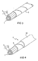
- FIGs. 1 to 5 show the structure of embodiment one mainly comprising insulator, hollow pipe with flame-retardant made of flexible material
- said hollow pipe can be a round hollow pipe 10 or a sectional flexible pipe 1 or a screw hollow pipe (not shown).
- the conductor 2 is axial direction along with the horizontally direction of the sectional flexible hollow pipe 1 (or round hollow pipe 10) so as to be arranged in order at the outside of the sectional flexible hollow pipe 1 (or round hollow pipe 10), or these conductors are axial direction by means of screw type along with the horizontally direction of the screw hollow pipe whereby to be arranged in order at the outside of the sectional flexible hollow pipe.
- Each conductor 2 can be a single core conductor or multiple conductors. It also can be produced by conducting material of copper, alumina or alloy.
- the structure of each conductor 2 is a metal conductor 21 covered with an insulator layer 22. Each metal conductor 21 is not to contact each other to keep insulating by means of said insulator layer 22. Further, the outside of each conductor 2 is winding together with an insulating belt 3 (as shown in Fig. 3 ). According to the demand of insulating or protection, the outer circumference of said insulating belt 3 is equipped with another insulator 30 (as shown in Fig. 4 ), so as to form a unit of cable wire A.
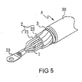
- the exposed terminal of the metal conductor 21 of each conductor 2 can be compressing or welding connection to connect to a connector 23, whereby to favor the unit of cable wire A to connect to the outside.
- the center of each conductor 2 keeps hollowing out with ventilating space, it is convenient to cool metal impedance in electric conduction occurring the heat, so as to reduce the temperature while using.
- the metal conductor 21 of each conductor 2 not to contact each other, it is able to take advantage of the skin effect of electric conduction, whereby to enhance the power output and transmission efficiency of the unit of cable wire A.
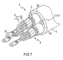
- Fig. 6 and Fig. 7 are the structures and performances of the second embodiment. As shown from each drawing, it is known that the structure of the second embodiment is based on the first embodiment. It is to take advantage of multiple cable wire A to line up in order with neighboring, and between each multiple cable wire A, a flexible hollow pipe and insulated filler 40 are equipped, such pipe can be sectional flexible hollow pipe 1, round hollow pipe 10 or screw hollow pipe, then the most outside flank equipped with together sheathing 4, finally the terminals of unit of cable wire A, i.e. the exposed terminal of metal conductor 21 of each conductor 2, are connected to the connector 23 so as to form a bigger structure of cable wire with electric conduction quantity.
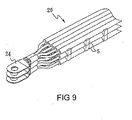
- Fig. 8 and Fig. 9 are the structures and performances of the third embodiment.
- the structure of the third embodiment is mainly the multiple conductors 2 lined up with single layer to form a conductor set 20 and between each conductor set 20 equipped with flat-belt shaped body 5.
- multiple sinking grooves 51, 52 are arranged and are able to match the outer peripheral shape and arrangement density of conductor 2 to clip and fix each layer of conductor set 20 respectively, so that between each layer of conductor set 20, a appropriate distance is kept.
- further multiple slit fin 53 are horizontally arranged at the center section of flat-belt shaped body 5 and the extending direction of said multiple slit fin 53 is same as that of conductor set 20 to penetrate the flat-belt shaped body 5. Said multiple slit fin 53 are able to promote the air circulation effect.
- the terminal part of conductor set 20 i.e. the exposed part of metal conductor 21 of the conductor 2 can be connected to connector post 24 so as to form another cable wire set structure more larger.
- Fig. 10 is perspective view of the combination of the fourth embodiment with the terminal of electric conductor of the present invention.
- the structure of the fourth embodiment is based on that of the first and the third embodiments. It is to take advantage of multiple cable wire A in single layer parallel arrangement to form a cable wire set B. Further, the same structure of flat-belt shaped body 5 is arranged between each cable wire set B (the structure and arrangement of flat-belt shaped body 5 are same as mentioned above).
- the terminal of each unit of cable wire A can be connected to connector post 23 so as to form another cable wire set structure with electric conduction quantity larger than that of mentioned above in the third embodiment.
- the structures mentioned in the above embodiments of the present invention are fully to take advantage of the skin effect of each metal conductor 21, Simultaneously, said structures equip with hollow and ventilating (sectional flexible hollow pipe 1, round hollow pipe 10, screw hollow pipe and slit fin 53) to cool down the heat formed by the metal. If it is able to limit the temperature not exceeding 40°C, it will increase the transportation electric quantity massively and effectively (owing to the electric transportation and because of metal impudence, the pass of electric current is able to generate heat. The more electric power, the more resistance, the generation heat is increasing accordingly. Owing to the heat in the conductor being not removed and for safety, it is to limit the temperature not exceeding 40°C so that the transportation electric quantity can be massively.
- a big area of metal conductor with 500mm 2 is done, for example, their safe electric current is 500 ampere inferior to the small area.
- the safe electric current benefit of metal conductor with 2mm 2 is high up to 20 ampere.
- the peripheral of the round flexible pipe is encircled by several insulated single core conductor 2 with 2mm 2 , or several layers with parallel of insulated conductor 2 are separated a suitable distance respectively whereby to have a good radiation function, under the safe electric current load standard, it is able to several insulated conductor 2 compressed and weld into a connector 23 or 24, i.e. the total sum of transportation electric current of each insulated conductor 2. Therefore, it is effective to save wire material of copper/alumina so as to increase the electric transmission power.
- a painted electric wire or wire enveloped by paint and covered with a slim plastic is used as conductor, it can reduce the electric wire outer diameter and save insulated material, further it is advantageous for the process of construction.
- the formation of the traditional 500mm 2 is to use 61 copper wire with ⁇ 3.2mm, the weight is 4448Kg per 1000 meter, the safe electric current is 500 ampere.
- the construction of the present invention is to use 25 copper wire with ⁇ 1.6mm, the safe electric current is also 500 ampere, the weight is 447Kg per 1000 meter.
- the load current of the present invention and the tradition one is the same, but in comparison with the present invention and the traditional one, the present invention can save the copper material of 4000Kg. The benefit is astonishing.
- the present invention of wire cable with saving energy is able to reduce the production cost, to increase the transportation electric power efficiency and to decrease the temperature increasing effect.
- the present invention is with the originality and progressive.
Landscapes
- Insulated Conductors (AREA)
- Connections Effected By Soldering, Adhesion, Or Permanent Deformation (AREA)
- Ropes Or Cables (AREA)
- Gas Or Oil Filled Cable Accessories (AREA)
- Non-Insulated Conductors (AREA)
Abstract
Description
- The present invention relates to a kind of wire cable with saving energy of electric conductor. Especially, it relates to a wire cable of electric conductor able to increase the effect of transportation of electricity and decrease (down low) the producing costs to protect the safety of the users.
- Owing to the demand of human being increasing, the natural souses in the earth are instantly and quickly consumptive. The resolving ways are positive to recovery the usable souse and restrict the assumption of the various naturally souses. In the modern human beings living, the electricity is extremely important. However, the transportations of electricity demand a large quantity of the metals of copper, aluminum, etc. Thus, if we can not influence the transportation of electricity, the quantity of the above mentioned metals of copper, aluminum, etc. can be decreased. It is nature to reach multiple effects of decreasing of the assumption of souses and also decreasing producing costs so as to increase the economical effects.
- According to the handbook of World Electric Engineering Handbook and under general situation, insulated PVC wire cable able to durable 600V of Φ1.6mm (cross section area 2mm2), their safe electric current is 20 ampere. That is the cross section area of each 1mm2 able to transport electric current of 10 ampere. Obviously, the efficiency of the transportations of electricity of the metal wire cable with larger cross section area is worse. Thus, it is the topic for the related entrepreneur urgently to endeavour diligently, how to increase the efficiency of the transportations of electricity of the metal wire cable with large cross section area and to decrease the use of large quantity of the metals of copper, aluminum.
- Concerning the traditional metal wire cable having the above-mentioned shortcoming, the present invention provides an improvement method in view of these shortcomings. Therefore, the purpose of the present invention is to provide a kind of wire cable with saving energy of electric conductor, which is completely to use the skin effect of metal wire cable so as to increase the quantity and efficiency of transportations of electricity of metal wire cable.
- The further purpose of the present invention is to provide wire cable with saving energy of electric conductor. It is able to save the consumption of a large quantity of the metals of copper, aluminum, etc. so as to reduce the production cost effectively and to save natural resources.
- Another purpose of the present invention is to provide wire cable with saving energy of electric conductor, by means of ventilating to cool the metal to resist the heat of electrifying, so as to effectively low down the temperature of wire cable while using.
- In order to achieve the above mentioned purposes, the present invention provides a kind of wire cable with saving energy of electric conductor comprising: multiple conductors, at least support body (element) along with axial direction to support said wire conductor, an insulator to cover the wire conductor and support body.
- Other objects, effects and features will become apparent when the description of preferred embodiments is taken in conjunction with the annexed drawings.
-
-
Fig. 1 is perspective view of a structure of the wire conductor with a principle hollow circle pipe of the present invention. -
Fig. 2 is perspective view of a screw structure of the wire conductor with a principle hollow circle pipe of the present invention. -
Fig. 3 is perspective view of the structure of the first aspect of the first embodiment of the present invention. -
Fig. 4 is perspective view of the structure of the second aspect of the first embodiment of the present invention. -
Fig. 5 is perspective view of the combination of the first embodiment with the terminal of electric conductor of the present invention. -
Fig. 6 is a cross sectional view of the structure of the first embodiment of the present invention. -
Fig. 7 is perspective view of the combination of the second embodiment with the terminal of electric conductor of the present invention. -
Fig. 8 is perspective view of the third embodiment of the present invention. -
Fig. 9 is perspective view of the combination of the third embodiment with the terminal of electric conductor of the present invention. -
Fig. 10 is perspective view of the combination of the fourth embodiment with the terminal of electric conductor of the present invention. - Now referring to
Figs. 1 to 5 , these drawings show the structure of embodiment one mainly comprising insulator, hollow pipe with flame-retardant made of flexible material, said hollow pipe can be a roundhollow pipe 10 or a sectionalflexible pipe 1 or a screw hollow pipe (not shown). While performance (practicing), theconductor 2 is axial direction along with the horizontally direction of the sectional flexible hollow pipe 1 (or round hollow pipe 10) so as to be arranged in order at the outside of the sectional flexible hollow pipe 1 (or round hollow pipe 10), or these conductors are axial direction by means of screw type along with the horizontally direction of the screw hollow pipe whereby to be arranged in order at the outside of the sectional flexible hollow pipe. Eachconductor 2 can be a single core conductor or multiple conductors. It also can be produced by conducting material of copper, alumina or alloy. The structure of eachconductor 2 is ametal conductor 21 covered with aninsulator layer 22. Eachmetal conductor 21 is not to contact each other to keep insulating by means of saidinsulator layer 22. Further, the outside of eachconductor 2 is winding together with an insulating belt 3 (as shown inFig. 3 ). According to the demand of insulating or protection, the outer circumference of saidinsulating belt 3 is equipped with another insulator 30 (as shown inFig. 4 ), so as to form a unit of cable wire A. Finally, the exposed terminal of themetal conductor 21 of eachconductor 2 can be compressing or welding connection to connect to aconnector 23, whereby to favor the unit of cable wire A to connect to the outside. Taking advantage of sectional flexiblehollow pipe 1, or roundhollow pipe 10, or screw hollow pipe, the center of eachconductor 2 keeps hollowing out with ventilating space, it is convenient to cool metal impedance in electric conduction occurring the heat, so as to reduce the temperature while using. Further, by means of themetal conductor 21 of eachconductor 2 not to contact each other, it is able to take advantage of the skin effect of electric conduction, whereby to enhance the power output and transmission efficiency of the unit of cable wire A. -
Fig. 6 andFig. 7 are the structures and performances of the second embodiment. As shown from each drawing, it is known that the structure of the second embodiment is based on the first embodiment. It is to take advantage of multiple cable wire A to line up in order with neighboring, and between each multiple cable wire A, a flexible hollow pipe and insulatedfiller 40 are equipped, such pipe can be sectional flexiblehollow pipe 1, roundhollow pipe 10 or screw hollow pipe, then the most outside flank equipped with together sheathing 4, finally the terminals of unit of cable wire A, i.e. the exposed terminal ofmetal conductor 21 of eachconductor 2, are connected to theconnector 23 so as to form a bigger structure of cable wire with electric conduction quantity. -
Fig. 8 andFig. 9 are the structures and performances of the third embodiment. As shown from each drawing, it is known that the structure of the third embodiment is mainly themultiple conductors 2 lined up with single layer to form aconductor set 20 and between each conductor set 20 equipped with flat-beltshaped body 5. At both side of the top and bottom of the flat-belt shapedbody 5,multiple sinking grooves conductor 2 to clip and fix each layer of conductor set 20 respectively, so that between each layer of conductor set 20, a appropriate distance is kept. Simultaneously, furthermultiple slit fin 53 are horizontally arranged at the center section of flat-belt shapedbody 5 and the extending direction of saidmultiple slit fin 53 is same as that of conductor set 20 to penetrate the flat-beltshaped body 5. Saidmultiple slit fin 53 are able to promote the air circulation effect. Finally, the terminal part of conductor set 20 (i.e. the exposed part ofmetal conductor 21 of the conductor 2) can be connected toconnector post 24 so as to form another cable wire set structure more larger. -
Fig. 10 is perspective view of the combination of the fourth embodiment with the terminal of electric conductor of the present invention. As shown in the drawing, it is well known that the structure of the fourth embodiment is based on that of the first and the third embodiments. It is to take advantage of multiple cable wire A in single layer parallel arrangement to form a cable wire set B. Further, the same structure of flat-beltshaped body 5 is arranged between each cable wire set B (the structure and arrangement of flat-beltshaped body 5 are same as mentioned above). The terminal of each unit of cable wire A can be connected toconnector post 23 so as to form another cable wire set structure with electric conduction quantity larger than that of mentioned above in the third embodiment. - The structures mentioned in the above embodiments of the present invention are fully to take advantage of the skin effect of each
metal conductor 21, Simultaneously, said structures equip with hollow and ventilating (sectional flexiblehollow pipe 1, roundhollow pipe 10, screw hollow pipe and slit fin 53) to cool down the heat formed by the metal. If it is able to limit the temperature not exceeding 40°C, it will increase the transportation electric quantity massively and effectively (owing to the electric transportation and because of metal impudence, the pass of electric current is able to generate heat. The more electric power, the more resistance, the generation heat is increasing accordingly. Owing to the heat in the conductor being not removed and for safety, it is to limit the temperature not exceeding 40°C so that the transportation electric quantity can be massively. A big area of metal conductor with 500mm2 is done, for example, their safe electric current is 500 ampere inferior to the small area. The safe electric current benefit of metal conductor with 2mm2 is high up to 20 ampere. In case, the peripheral of the round flexible pipe is encircled by several insulatedsingle core conductor 2 with 2mm2, or several layers with parallel of insulatedconductor 2 are separated a suitable distance respectively whereby to have a good radiation function, under the safe electric current load standard, it is able to several insulatedconductor 2 compressed and weld into aconnector conductor 2. Therefore, it is effective to save wire material of copper/alumina so as to increase the electric transmission power. In case, a painted electric wire or wire enveloped by paint and covered with a slim plastic is used as conductor, it can reduce the electric wire outer diameter and save insulated material, further it is advantageous for the process of construction. For example: the formation of the traditional 500mm2 is to use 61 copper wire with Φ3.2mm, the weight is 4448Kg per 1000 meter, the safe electric current is 500 ampere. However, the construction of the present invention is to use 25 copper wire with Φ1.6mm, the safe electric current is also 500 ampere, the weight is 447Kg per 1000 meter. The load current of the present invention and the tradition one is the same, but in comparison with the present invention and the traditional one, the present invention can save the copper material of 4000Kg. The benefit is astonishing. Take copper wire with Φ1.6mm as the example, if is substituted by alumina wire, it is able to increase the cross-section up to 30%. Even the single wire with Φ1.83mm diameter used, it is still able to transport the safe electric current with 20 ampere. The alumina wire is used to transport electric power with 500 ampere and it is only to use 25 alumina wire with Φ1.83mm, their weight is 235Kg per 1000 meter. It is outstanding benefit to save the copper and alumina sources. - The present invention of wire cable with saving energy is able to reduce the production cost, to increase the transportation electric power efficiency and to decrease the temperature increasing effect. The present invention is with the originality and progressive. From the foregoing, it will be appreciated that although the specific embodiments of the invention have been described herein for purposed of illustration, various modifications and improvements thereon will become readily apparent to those skilled in the art. Accordingly, the appended claims are to be construed broadly and in a manner consistent with the spirit and scope of the invention described herein.
-
- 1
- sectional flexible hollow pipe
- 10
- round flexible pipe
- 2
- conductor
- 20
- conductor set
- 21
- metal conductor
- 22
- insulated layer
- 23
- connector post
- 24
- connector post
- 3
- insulating belt
- 30
- insulator
- 4
- sheathing
- 40
- insulated filler
- 5
- flat-belt shaped body
- 51
- sinking grooves
- 52
- sinking grooves
- 53
- slit fin
- A
- unit of cable wire
- B
- cable wire set
Claims (14)
- A wire cable of electric conductor with saving energy forming of multiple conductors, at least support body along with axial direction to support said wire conductor, an insulator to cover the wire conductor and support body.
- A wire cable of electric conductor with saving energy as claimed in claim 1, wherein the support body being a round hollow pipe, the conductors being axial direction along with the horizontally direction of the round hollow pipe so as to be arranged in order outside of the round hollow pipe
- A wire cable of electric conductor with saving energy as claimed in claim 1, wherein the support body being a round hollow pipe, the conductors being axial direction along with the horizontally direction of the screw hollow pipe so as to be arranged in order outside of the screw hollow pipe.
- A wire cable of electric conductor with saving energy as claimed in claim 1, wherein the support body being a round hollow pipe, the conductors being axial direction along with the horizontally direction of the sectional flexible hollow pipe so as to be arranged in order outside of the sectional flexible hollow pipe
- A wire cable of electric conductor with saving energy as claimed in claim 1, wherein the support body being a flat-belt shaped body along with the axial direction of conductors to support the conductors.
- A wire cable of electric conductor with saving energy as claimed in claim 5, wherein the flat-belt shaped body equipped with sinking groove to arrange the conductors respectively.
- A wire cable of electric conductor with saving energy as claimed in claim 1, wherein the conductors being a single core respectively.
- A wire cable of electric conductor with saving energy as claimed in claim 1, wherein the conductors being multiple cores respectively.
- The wire cable of electric conductor with saving energy as claimed in claim 1, wherein an insulator being further comprising to cover the wire conductors and support body.
- The wire cable of electric conductor with saving energy as claimed in claim 1, wherein the insulator being filled between the wire conductors and support body.
- The wire cable of electric conductor with saving energy as claimed in claim 1, wherein the electric conduction post being further contained whereby to connect the terminal of wire conductors.
- The wire cable of electric conductor with saving energy as claimed in claim 11, wherein the electric conduction post being compression and weld with the terminal of wire conductors.
- The wire cable of electric conductor with saving energy as claimed in claim 11, wherein the electric conduction post welding with the terminal of wire conductors.
- The wire cable of electric conductor with saving energy as claimed in claim 11, wherein the wire conductors are made by conducting material of copper, alumina or alloys.
Applications Claiming Priority (1)
| Application Number | Priority Date | Filing Date | Title |
|---|---|---|---|
| TW097200938U TWM340532U (en) | 2008-01-15 | 2008-01-15 | Energy-saving electric wire and cable |
Publications (2)
| Publication Number | Publication Date |
|---|---|
| EP2081196A2 true EP2081196A2 (en) | 2009-07-22 |
| EP2081196A3 EP2081196A3 (en) | 2010-08-18 |
Family
ID=40588754
Family Applications (1)
| Application Number | Title | Priority Date | Filing Date |
|---|---|---|---|
| EP09150320A Withdrawn EP2081196A3 (en) | 2008-01-15 | 2009-01-09 | Wire cable for saving energy |
Country Status (5)
| Country | Link |
|---|---|
| US (1) | US7772495B2 (en) |
| EP (1) | EP2081196A3 (en) |
| JP (1) | JP2009170426A (en) |
| KR (1) | KR20090078755A (en) |
| TW (1) | TWM340532U (en) |
Cited By (5)
| Publication number | Priority date | Publication date | Assignee | Title |
|---|---|---|---|---|
| CN101789282A (en) * | 2010-03-18 | 2010-07-28 | 黄武槐 | Novel short-circuit-proof power wire |
| WO2012079861A1 (en) * | 2010-12-16 | 2012-06-21 | Conductix-Wampfler Ag | Device for the inductive transmission of electrical energy |
| FR2989817A1 (en) * | 2012-04-24 | 2013-10-25 | Fives Celes | CABLE IN LITZ THREAD |
| TWI708268B (en) * | 2018-01-19 | 2020-10-21 | 日商發那科股份有限公司 | Cable |
| EP3767752A1 (en) | 2019-07-18 | 2021-01-20 | Rosenberger Hochfrequenztechnik GmbH & Co. KG | Assembled electrical cable, method for assembling an electrical cable and electrical plug-in connection |
Families Citing this family (41)
| Publication number | Priority date | Publication date | Assignee | Title |
|---|---|---|---|---|
| JP5438753B2 (en) * | 2009-03-25 | 2014-03-12 | 大電株式会社 | Strip material for moving parts |
| TW201117232A (en) * | 2009-11-13 | 2011-05-16 | Wei-Ren Liu | Conductor fixing member, highly-conductive and energy-saving electric cable, highly-conductive and energy-saving electric cable assembly and its manufacturing method |
| TWM383805U (en) * | 2010-02-10 | 2010-07-01 | Li-Wen Liu | Conductor with tip section and conduct-column, high conductivity and high energy saving cable, and high conductivity and high energy saving cable assembly |
| US8568015B2 (en) | 2010-09-23 | 2013-10-29 | Willis Electric Co., Ltd. | Decorative light string for artificial lighted tree |
| US9157587B2 (en) | 2011-11-14 | 2015-10-13 | Willis Electric Co., Ltd. | Conformal power adapter for lighted artificial tree |
| US8569960B2 (en) | 2011-11-14 | 2013-10-29 | Willis Electric Co., Ltd | Conformal power adapter for lighted artificial tree |
| JP6002985B2 (en) * | 2011-12-27 | 2016-10-05 | 矢崎総業株式会社 | Intermediate member for wire harness and wire harness |
| JP5875386B2 (en) * | 2012-01-25 | 2016-03-02 | 太陽ケーブルテック株式会社 | Movable cable |
| US9044056B2 (en) | 2012-05-08 | 2015-06-02 | Willis Electric Co., Ltd. | Modular tree with electrical connector |
| US9450389B2 (en) * | 2013-03-05 | 2016-09-20 | Yaroslav A. Pichkur | Electrical power transmission system and method |
| US10267464B2 (en) | 2015-10-26 | 2019-04-23 | Willis Electric Co., Ltd. | Tangle-resistant decorative lighting assembly |
| US9140438B2 (en) | 2013-09-13 | 2015-09-22 | Willis Electric Co., Ltd. | Decorative lighting with reinforced wiring |
| US9157588B2 (en) | 2013-09-13 | 2015-10-13 | Willis Electric Co., Ltd | Decorative lighting with reinforced wiring |
| US10923267B2 (en) | 2014-09-05 | 2021-02-16 | Yaroslav A. Pichkur | Transformer |
| DE102015114133A1 (en) * | 2015-08-26 | 2017-03-02 | Phoenix Contact E-Mobility Gmbh | Power cable with a cooling line |
| CN105225726A (en) * | 2015-11-07 | 2016-01-06 | 中利科技集团股份有限公司 | A tubular ventilated and cooled five-core flexible cable and its manufacturing method |
| DE102016209607A1 (en) * | 2016-06-01 | 2017-12-07 | Phoenix Contact E-Mobility Gmbh | Charging cable for transmitting electrical energy, charging plug and charging station for delivering electrical energy to a receiver of electrical energy |
| JP6078198B1 (en) | 2016-07-29 | 2017-02-08 | 株式会社フジクラ | Power supply cable and power supply cable with connector |
| DE102016224106A1 (en) * | 2016-12-05 | 2018-06-07 | Leoni Kabel Gmbh | High current cable and power supply system with high current cable |
| DE102016224104A1 (en) * | 2016-12-05 | 2018-06-07 | Leoni Kabel Gmbh | High current cable and power supply system with high current cable |
| JP2018018809A (en) * | 2017-01-05 | 2018-02-01 | 株式会社フジクラ | Power supply cable and power supply cable with connector |
| JP6201069B1 (en) * | 2017-01-27 | 2017-09-20 | 株式会社フジクラ | Power supply cable and power supply cable with connector |
| JP6408619B2 (en) * | 2017-01-31 | 2018-10-17 | 株式会社フジクラ | Power supply cable and power supply cable with connector |
| JP6201071B1 (en) * | 2017-02-07 | 2017-09-20 | 株式会社フジクラ | Power supply cable and power supply cable with connector |
| DE102017105985A1 (en) * | 2017-03-21 | 2018-09-27 | Dr. Ing. H.C. F. Porsche Aktiengesellschaft | Charging cable assembly |
| JP2018018837A (en) * | 2017-11-01 | 2018-02-01 | 株式会社フジクラ | Feed cable and connector-fitted feed cable |
| DE102018102207A1 (en) * | 2018-02-01 | 2019-08-01 | Dr. Ing. H.C. F. Porsche Aktiengesellschaft | Vehicle charging cable |
| DE102018122680B3 (en) * | 2018-09-17 | 2020-02-20 | Dr. Ing. H.C. F. Porsche Aktiengesellschaft | Vehicle charging cable |
| WO2020117369A2 (en) * | 2018-10-14 | 2020-06-11 | Metal Oxide Technologies, Llc. | Superconductor flux pinning without columnar defects |
| DE102019208685A1 (en) * | 2019-06-14 | 2020-12-17 | Vitesco Technologies GmbH | Power cables |
| EP3770925B1 (en) * | 2019-07-25 | 2023-12-27 | ABB E-mobility B.V. | Heavy-current charging cable for charging an electric vehicle |
| CN112712927A (en) * | 2019-10-24 | 2021-04-27 | 李政 | Transmission cable |
| JP7463859B2 (en) * | 2020-06-08 | 2024-04-09 | 株式会社オートネットワーク技術研究所 | Wire Harness Unit |
| JP7463860B2 (en) * | 2020-06-08 | 2024-04-09 | 株式会社オートネットワーク技術研究所 | Wire Harness Unit |
| EP3929945A1 (en) * | 2020-06-26 | 2021-12-29 | Huber+Suhner AG | Liquid cooled cable and charging cable assembly |
| JP7524672B2 (en) * | 2020-08-26 | 2024-07-30 | 住友電装株式会社 | Wire Harness Unit |
| CN114446523A (en) * | 2020-11-04 | 2022-05-06 | 进营全球株式会社 | Flexible flat cable and laminated busbar comprising same |
| CN113450963A (en) * | 2021-07-14 | 2021-09-28 | 浙江吉利控股集团有限公司 | Power cable and cooling cable |
| DE102021208427A1 (en) | 2021-08-04 | 2023-02-09 | Leoni Bordnetz-Systeme Gmbh | Electrical line, in particular high-current line and device with such an electrical line |
| EP4163934A1 (en) * | 2021-10-11 | 2023-04-12 | Aptiv Technologies Limited | High voltage power cable |
| DE102023109084A1 (en) * | 2023-04-11 | 2024-10-17 | Huber+Suhner Ag | cable assembly |
Citations (1)
| Publication number | Priority date | Publication date | Assignee | Title |
|---|---|---|---|---|
| US5519173A (en) * | 1994-06-30 | 1996-05-21 | Berk-Tek, Inc. | High speed telecommunication cable |
Family Cites Families (16)
| Publication number | Priority date | Publication date | Assignee | Title |
|---|---|---|---|---|
| US1701808A (en) * | 1929-02-12 | Best available | ||
| US2081634A (en) * | 1934-09-27 | 1937-05-25 | American Steel & Wire Co | Electric cord or cable |
| US2804494A (en) * | 1953-04-08 | 1957-08-27 | Charles F Fenton | High frequency transmission cable |
| FR2341187A1 (en) * | 1976-02-16 | 1977-09-09 | Chavanoz Sa | REMOTE CONTROL CABLE |
| US4409431A (en) * | 1981-08-07 | 1983-10-11 | Harvey Hubbell Incorporated | Oil well cable |
| GB2133206B (en) * | 1982-12-15 | 1986-06-04 | Standard Telephones Cables Ltd | Cable manufacture |
| US4767890A (en) * | 1986-11-17 | 1988-08-30 | Magnan David L | High fidelity audio cable |
| US4795380A (en) * | 1987-12-22 | 1989-01-03 | Amp Incorporated | Self-locking ring terminal |
| GB2258940A (en) * | 1991-08-17 | 1993-02-24 | Lin Lieh Chao | Electrical cable |
| DE19723879C1 (en) * | 1997-06-06 | 1998-08-13 | Felten & Guilleaume Energie | Cable installation for high-power transmission by HV cable with cooling pipe |
| US6100467A (en) * | 1998-02-19 | 2000-08-08 | Flex-Cable, Inc. | Water cooled kickless electrical cable |
| NZ509613A (en) * | 1998-08-06 | 2002-12-20 | Prestolite Wire Corp | Cable, for telecommunications, with even number of paired conductors evenly divided into groups of at least two conductor pairs, with even number surrounding additional pair of conductors encircled around filler material |
| US6162992A (en) * | 1999-03-23 | 2000-12-19 | Cable Design Technologies, Inc. | Shifted-plane core geometry cable |
| ATE308793T1 (en) * | 2001-03-14 | 2005-11-15 | Leoni Kabel Gmbh & Co Kg | TRANSMISSION CABLE FOR MEDICAL SIGNAL VALUES |
| US6713673B2 (en) * | 2002-06-27 | 2004-03-30 | Capativa Tech, Inc. | Structure of speaker signal line |
| US20050087360A1 (en) * | 2003-10-24 | 2005-04-28 | Speer Richard W. | Cable having a filler |
-
2008
- 2008-01-15 TW TW097200938U patent/TWM340532U/en not_active IP Right Cessation
-
2009
- 2009-01-06 US US12/349,162 patent/US7772495B2/en not_active Expired - Fee Related
- 2009-01-09 EP EP09150320A patent/EP2081196A3/en not_active Withdrawn
- 2009-01-14 KR KR1020090002954A patent/KR20090078755A/en not_active Ceased
- 2009-01-15 JP JP2009006911A patent/JP2009170426A/en active Pending
Patent Citations (1)
| Publication number | Priority date | Publication date | Assignee | Title |
|---|---|---|---|---|
| US5519173A (en) * | 1994-06-30 | 1996-05-21 | Berk-Tek, Inc. | High speed telecommunication cable |
Cited By (9)
| Publication number | Priority date | Publication date | Assignee | Title |
|---|---|---|---|---|
| CN101789282A (en) * | 2010-03-18 | 2010-07-28 | 黄武槐 | Novel short-circuit-proof power wire |
| WO2012079861A1 (en) * | 2010-12-16 | 2012-06-21 | Conductix-Wampfler Ag | Device for the inductive transmission of electrical energy |
| US9473211B2 (en) | 2010-12-16 | 2016-10-18 | Conductix Wampfler Gmbh | Device for the inductive transmission of electrical energy |
| FR2989817A1 (en) * | 2012-04-24 | 2013-10-25 | Fives Celes | CABLE IN LITZ THREAD |
| WO2013160819A1 (en) * | 2012-04-24 | 2013-10-31 | Fives Celes | Cable made of litz wires |
| CN104364855A (en) * | 2012-04-24 | 2015-02-18 | 法孚斯塞莱斯公司 | Cable made of litz wires |
| TWI708268B (en) * | 2018-01-19 | 2020-10-21 | 日商發那科股份有限公司 | Cable |
| EP3767752A1 (en) | 2019-07-18 | 2021-01-20 | Rosenberger Hochfrequenztechnik GmbH & Co. KG | Assembled electrical cable, method for assembling an electrical cable and electrical plug-in connection |
| US11749925B2 (en) | 2019-07-18 | 2023-09-05 | Rosenberger Hochfrequenztechnik Gmbh & Co. Kg | Assembled electrical cable, method for assembling an electrical cable, and electrical plug connection |
Also Published As
| Publication number | Publication date |
|---|---|
| TWM340532U (en) | 2008-09-11 |
| JP2009170426A (en) | 2009-07-30 |
| EP2081196A3 (en) | 2010-08-18 |
| US7772495B2 (en) | 2010-08-10 |
| KR20090078755A (en) | 2009-07-20 |
| US20090178825A1 (en) | 2009-07-16 |
Similar Documents
| Publication | Publication Date | Title |
|---|---|---|
| EP2081196A2 (en) | Wire cable for saving energy | |
| CN1809900A (en) | superconducting cable | |
| RU2476965C2 (en) | Cable with parallel structure and reinforcement for high conductivity conductors | |
| CN108447614A (en) | A kind of quasi-isotropic high engineering current density high-temperature superconductor conductor | |
| CN103532064B (en) | Low-voltage hollow bus duct | |
| CN114843023A (en) | Charging cables and charging piles | |
| CN203706693U (en) | Rated 450V or 750V fluoroplastic insulation and sheath high temperature resisting control cable | |
| CN201222365Y (en) | Aluminum cable steel reinforced aerial insulated cable | |
| CN201984888U (en) | Self-supporting landscape lamp cable | |
| CN103377758A (en) | Aluminum alloy cable | |
| CN213585080U (en) | High-strength heat dissipation copper bus | |
| CN201075309Y (en) | Copper core enclosed bus bar | |
| CN203465960U (en) | Copper-coated aluminum alloy conductor cable for automobile | |
| CN202134222U (en) | A conductive wire core and the power cable made thereof | |
| CN206992318U (en) | A kind of copper aluminum conductor attachment structure | |
| CN207489570U (en) | A kind of novel 10kV aerial condutors | |
| CN202487197U (en) | New aluminum-clad steel-cored aluminum stranded wire | |
| CN206774688U (en) | Integrated busbar joint | |
| CN218997102U (en) | Binding post of copper aluminium composite power cable | |
| CN205828502U (en) | A kind of connecting line construction of multiple battery | |
| CN223451233U (en) | Bus connection structure | |
| CN222394588U (en) | Light alternating-current charging wire for vehicle | |
| CN209822320U (en) | Anti-winding cable | |
| CN214956051U (en) | A compact D-shaped aluminum alloy conductor photovoltaic cable | |
| CN201477973U (en) | A new type of power cable |
Legal Events
| Date | Code | Title | Description |
|---|---|---|---|
| PUAI | Public reference made under article 153(3) epc to a published international application that has entered the european phase |
Free format text: ORIGINAL CODE: 0009012 |
|
| AK | Designated contracting states |
Kind code of ref document: A2 Designated state(s): AT BE BG CH CY CZ DE DK EE ES FI FR GB GR HR HU IE IS IT LI LT LU LV MC MK MT NL NO PL PT RO SE SI SK TR |
|
| AX | Request for extension of the european patent |
Extension state: AL BA RS |
|
| PUAL | Search report despatched |
Free format text: ORIGINAL CODE: 0009013 |
|
| AK | Designated contracting states |
Kind code of ref document: A3 Designated state(s): AT BE BG CH CY CZ DE DK EE ES FI FR GB GR HR HU IE IS IT LI LT LU LV MC MK MT NL NO PL PT RO SE SI SK TR |
|
| AX | Request for extension of the european patent |
Extension state: AL BA RS |
|
| 17P | Request for examination filed |
Effective date: 20110218 |
|
| AKX | Designation fees paid |
Designated state(s): AT BE BG CH CY CZ DE DK EE ES FI FR GB GR HR HU IE IS IT LI LT LU LV MC MK MT NL NO PL PT RO SE SI SK TR |
|
| 17Q | First examination report despatched |
Effective date: 20131010 |
|
| STAA | Information on the status of an ep patent application or granted ep patent |
Free format text: STATUS: THE APPLICATION IS DEEMED TO BE WITHDRAWN |
|
| 18D | Application deemed to be withdrawn |
Effective date: 20150801 |