EP2081155B1 - Traitement d'image à base de prédiction - Google Patents
Traitement d'image à base de prédiction Download PDFInfo
- Publication number
- EP2081155B1 EP2081155B1 EP08164269A EP08164269A EP2081155B1 EP 2081155 B1 EP2081155 B1 EP 2081155B1 EP 08164269 A EP08164269 A EP 08164269A EP 08164269 A EP08164269 A EP 08164269A EP 2081155 B1 EP2081155 B1 EP 2081155B1
- Authority
- EP
- European Patent Office
- Prior art keywords
- prediction
- subblock
- variance
- representation
- block
- Prior art date
- Legal status (The legal status is an assumption and is not a legal conclusion. Google has not performed a legal analysis and makes no representation as to the accuracy of the status listed.)
- Not-in-force
Links
- 238000012545 processing Methods 0.000 title description 8
- 238000000034 method Methods 0.000 claims description 89
- 238000013139 quantization Methods 0.000 claims description 23
- 238000005070 sampling Methods 0.000 abstract description 8
- 230000006835 compression Effects 0.000 description 57
- 238000007906 compression Methods 0.000 description 57
- 239000000872 buffer Substances 0.000 description 42
- 238000010586 diagram Methods 0.000 description 36
- 230000006870 function Effects 0.000 description 19
- 230000006837 decompression Effects 0.000 description 16
- 238000004422 calculation algorithm Methods 0.000 description 14
- 238000012360 testing method Methods 0.000 description 10
- 238000013507 mapping Methods 0.000 description 8
- 229910052799 carbon Inorganic materials 0.000 description 5
- 238000004364 calculation method Methods 0.000 description 4
- 238000000354 decomposition reaction Methods 0.000 description 4
- 230000001419 dependent effect Effects 0.000 description 4
- 238000011156 evaluation Methods 0.000 description 4
- 238000011835 investigation Methods 0.000 description 4
- 230000008569 process Effects 0.000 description 4
- 230000003044 adaptive effect Effects 0.000 description 3
- 238000013459 approach Methods 0.000 description 3
- 230000003247 decreasing effect Effects 0.000 description 3
- 238000012886 linear function Methods 0.000 description 3
- 238000012986 modification Methods 0.000 description 3
- 230000004048 modification Effects 0.000 description 3
- 230000002441 reversible effect Effects 0.000 description 3
- 230000011664 signaling Effects 0.000 description 3
- XUIMIQQOPSSXEZ-UHFFFAOYSA-N Silicon Chemical compound [Si] XUIMIQQOPSSXEZ-UHFFFAOYSA-N 0.000 description 2
- 238000009825 accumulation Methods 0.000 description 2
- 239000003086 colorant Substances 0.000 description 2
- 230000007246 mechanism Effects 0.000 description 2
- 238000005457 optimization Methods 0.000 description 2
- 229910052710 silicon Inorganic materials 0.000 description 2
- 239000010703 silicon Substances 0.000 description 2
- 230000001131 transforming effect Effects 0.000 description 2
- 230000000007 visual effect Effects 0.000 description 2
- XLYOFNOQVPJJNP-UHFFFAOYSA-N water Substances O XLYOFNOQVPJJNP-UHFFFAOYSA-N 0.000 description 2
- 230000003466 anti-cipated effect Effects 0.000 description 1
- 230000000052 comparative effect Effects 0.000 description 1
- 230000000694 effects Effects 0.000 description 1
- 238000002474 experimental method Methods 0.000 description 1
- 238000003384 imaging method Methods 0.000 description 1
- 230000008450 motivation Effects 0.000 description 1
- 229910052760 oxygen Inorganic materials 0.000 description 1
- 230000009467 reduction Effects 0.000 description 1
- 238000009877 rendering Methods 0.000 description 1
- 238000004088 simulation Methods 0.000 description 1
- 229910052717 sulfur Inorganic materials 0.000 description 1
- 230000009466 transformation Effects 0.000 description 1
Images


Classifications
-
- G—PHYSICS
- G06—COMPUTING; CALCULATING OR COUNTING
- G06T—IMAGE DATA PROCESSING OR GENERATION, IN GENERAL
- G06T9/00—Image coding
-
- H—ELECTRICITY
- H04—ELECTRIC COMMUNICATION TECHNIQUE
- H04N—PICTORIAL COMMUNICATION, e.g. TELEVISION
- H04N19/00—Methods or arrangements for coding, decoding, compressing or decompressing digital video signals
- H04N19/10—Methods or arrangements for coding, decoding, compressing or decompressing digital video signals using adaptive coding
- H04N19/102—Methods or arrangements for coding, decoding, compressing or decompressing digital video signals using adaptive coding characterised by the element, parameter or selection affected or controlled by the adaptive coding
- H04N19/103—Selection of coding mode or of prediction mode
- H04N19/11—Selection of coding mode or of prediction mode among a plurality of spatial predictive coding modes
-
- H—ELECTRICITY
- H04—ELECTRIC COMMUNICATION TECHNIQUE
- H04N—PICTORIAL COMMUNICATION, e.g. TELEVISION
- H04N19/00—Methods or arrangements for coding, decoding, compressing or decompressing digital video signals
- H04N19/10—Methods or arrangements for coding, decoding, compressing or decompressing digital video signals using adaptive coding
- H04N19/134—Methods or arrangements for coding, decoding, compressing or decompressing digital video signals using adaptive coding characterised by the element, parameter or criterion affecting or controlling the adaptive coding
- H04N19/136—Incoming video signal characteristics or properties
- H04N19/14—Coding unit complexity, e.g. amount of activity or edge presence estimation
-
- H—ELECTRICITY
- H04—ELECTRIC COMMUNICATION TECHNIQUE
- H04N—PICTORIAL COMMUNICATION, e.g. TELEVISION
- H04N19/00—Methods or arrangements for coding, decoding, compressing or decompressing digital video signals
- H04N19/10—Methods or arrangements for coding, decoding, compressing or decompressing digital video signals using adaptive coding
- H04N19/169—Methods or arrangements for coding, decoding, compressing or decompressing digital video signals using adaptive coding characterised by the coding unit, i.e. the structural portion or semantic portion of the video signal being the object or the subject of the adaptive coding
- H04N19/17—Methods or arrangements for coding, decoding, compressing or decompressing digital video signals using adaptive coding characterised by the coding unit, i.e. the structural portion or semantic portion of the video signal being the object or the subject of the adaptive coding the unit being an image region, e.g. an object
- H04N19/176—Methods or arrangements for coding, decoding, compressing or decompressing digital video signals using adaptive coding characterised by the coding unit, i.e. the structural portion or semantic portion of the video signal being the object or the subject of the adaptive coding the unit being an image region, e.g. an object the region being a block, e.g. a macroblock
-
- H—ELECTRICITY
- H04—ELECTRIC COMMUNICATION TECHNIQUE
- H04N—PICTORIAL COMMUNICATION, e.g. TELEVISION
- H04N19/00—Methods or arrangements for coding, decoding, compressing or decompressing digital video signals
- H04N19/42—Methods or arrangements for coding, decoding, compressing or decompressing digital video signals characterised by implementation details or hardware specially adapted for video compression or decompression, e.g. dedicated software implementation
- H04N19/423—Methods or arrangements for coding, decoding, compressing or decompressing digital video signals characterised by implementation details or hardware specially adapted for video compression or decompression, e.g. dedicated software implementation characterised by memory arrangements
- H04N19/426—Methods or arrangements for coding, decoding, compressing or decompressing digital video signals characterised by implementation details or hardware specially adapted for video compression or decompression, e.g. dedicated software implementation characterised by memory arrangements using memory downsizing methods
-
- H—ELECTRICITY
- H04—ELECTRIC COMMUNICATION TECHNIQUE
- H04N—PICTORIAL COMMUNICATION, e.g. TELEVISION
- H04N19/00—Methods or arrangements for coding, decoding, compressing or decompressing digital video signals
- H04N19/46—Embedding additional information in the video signal during the compression process
-
- H—ELECTRICITY
- H04—ELECTRIC COMMUNICATION TECHNIQUE
- H04N—PICTORIAL COMMUNICATION, e.g. TELEVISION
- H04N19/00—Methods or arrangements for coding, decoding, compressing or decompressing digital video signals
- H04N19/50—Methods or arrangements for coding, decoding, compressing or decompressing digital video signals using predictive coding
- H04N19/593—Methods or arrangements for coding, decoding, compressing or decompressing digital video signals using predictive coding involving spatial prediction techniques
-
- H—ELECTRICITY
- H04—ELECTRIC COMMUNICATION TECHNIQUE
- H04N—PICTORIAL COMMUNICATION, e.g. TELEVISION
- H04N19/00—Methods or arrangements for coding, decoding, compressing or decompressing digital video signals
- H04N19/90—Methods or arrangements for coding, decoding, compressing or decompressing digital video signals using coding techniques not provided for in groups H04N19/10-H04N19/85, e.g. fractals
- H04N19/96—Tree coding, e.g. quad-tree coding
Definitions
- the present invention generally relates to image processing, and in particular to prediction-based compression and decompression of pixel blocks.
- a graphics system typically uses at least two buffers: a color buffer where the colors of the pixels are drawn and a depth buffer where the depth of each pixel is stored. During rendering these buffers are read and written to, and often the same pixel is accessed several times for both buffers. These read and write accesses are expensive in terms of energy and should therefore be kept to a minimum, in particular for user terminals with limited power supply, such as mobile devices.
- Buffer compression implies that blocks of buffer data is stored in memory in compressed form.
- Documents [1] and [2] give good overviews of prior art color buffer compression and depth buffer compression, respectively.
- Buffer data leads to an important problem as it may involve sharp edges between the drawn triangle and the background.
- Traditional buffer data techniques may run into problems when having a prediction-based buffer compression by predicting over the edge of such discontinuities.
- the present invention overcomes these and other drawbacks of the prior art arrangements.
- the present invention involves compression and decompression of blocks of pixels having associated property values.
- the compression involves sub-sampling at least a portion of the pixels in the block by defining a hierarchical tree structure. This sub-sampling is conducted by hierarchically replacing a set of multiple pixels or multiple hierarchically lower subblocks with a (hierarchically higher) subblock.
- a property value for the subblock is determined based on at least a portion of the property values of the sub-sampled set of pixels/subblocks.
- a prediction of the property value of the subblock is determined by calculating a variance measure for the subblock.
- This variance measure is descriptive of the variance in property values of neighboring pixels/subblocks in a first prediction direction and of neighboring pixels/subblocks in a second prediction direction.
- the variance measure is compared to a variance threshold and the pixels/subblocks to use as basis in the prediction calculation are determined from this comparison.
- the prediction is calculated based on a weighted combination of at least one neighboring property value in the first direction and at least one neighboring value in the second direction.
- the prediction is instead calculated based on at least one neighboring property value in only one of the first and second direction.
- a so-called guiding bit associated with the selected prediction direction is provided and included in the compressed block.
- a prediction error is calculated for the subblock based on its property value and the calculated prediction.
- the generated compressed block comprises an encoded representation of this calculated prediction error plus the guiding bit if determined for the current subblock, and preferably a tree code representative of the hierarchical tree structure.
- Decompression of the compressed block involves determination of a prediction error for a subblock to decode. This prediction error is determined based on the encoded error representation associated with the subblock and included in the compressed block. A prediction of the property value of the subblock is then provided.
- a variance measure is calculated based on the already dedoded, neighboring pixels/subblocks in the two prediction directions. If the variance measure is smaller than the threshold, the prediction is calculated based on the weighted combination of property values of neighboring pixels/subblock in both directions. However, in case the variance measure exceeds the threshold, a guiding bit assigned to the subblock and included in the compressed block is employed in the prediction provision. The guiding bit dictates from which of the two prediction directions to identify the at least one neighboring pixel/subblock to use as basis for calculating the property value prediction.
- the property value of the subblock is obtained from the determined error prediction and the provided prediction.
- the invention also relates to a compressor and decompressor.
- the present technology avoids doing prediction across unnaturally sharp discontinuity edges. As a consequence, pixel blocks having such discontinuities in property values between different pixel positions can be effectively handled.
- the present invention generally relates to compression and decompression of pixel property values, and in particular such a compression and decompression suitable for buffer compression and decompression.
- Buffer compression/decompression can be used in three-dimensional (3D) graphics, such as games, 3D maps and scenes, 3D messages, e.g. animated messages, screen savers, man-machine interfaces (MMIs), etc., but is not limited thereto.
- 3D graphics such as games, 3D maps and scenes
- 3D messages e.g. animated messages, screen savers, man-machine interfaces (MMIs), etc.
- MMIs man-machine interfaces
- the invention could also be employed for encoding other types of images or graphics, e.g. one-dimensional (1D), two-dimensional (2D) or 3D images.
- a pixel block has the size of M ⁇ N pixels, where M , N are integer numbers with the proviso that both M and N are not simultaneously one.
- pixel or "block element” refers to an element in a block or encoded representation of a block. This block, in turn, corresponds to a portion of an image, texture or buffer.
- a pixel could be a texel (texture element) of a (1D, 2D, 3D) texture, a pixel of a (1D or 2D) image or a voxel (volume element) of a 3D image.
- a pixel is characterized with an associated pixel parameter or property value or feature. There are different such characteristic property values that can be assigned to pixels, typically dependent on what kind of pixel block to compress/decompress. For instance, the property value could be a color value assigned to the pixel.
- RGB red, green, blue
- a pixel color can also be expressed in the form of luminance and chrominance components.
- a transform can be used for converting a RGB color value into a luminance value and, typically, two chrominance components.
- luminance-chrominance spaces in the art include YUV, YC o C g and YC r C b .
- a property value of the invention can therefore also be such a luminance value (Y) or a chrominance value (U, V, C o , Cg, C r or C b ).
- RGB colors of pixels are preferably converted into the luminance/chrominance color space.
- a particular color space transform to use is the YC o C g transform disclosed in document [3].
- This transform has low implementation complexity, i.e. is highly silicon-efficient, and provides good decorrelation.
- a further important feature is that is reversible: transforming the YC o C g values back to RGB recreates the RGB values bit-exactly.
- the present invention is though not limited to compressing/decompressing blocks where the pixels have assigned color values as property values.
- the invention can also be used in connection with, for instance, depth buffer compression/decompression. Then each pixel of a pixel block has a so-called depth value or Z value as property value.
- the embodiments herein can indeed be used in compressing/decompressing pixel blocks where the included pixels have any pixel property feature available in the art.
- the embodiments are, though, mainly discussed further in connection with color buffer compression, where each pixel has, following color space transformation, a luminance value and at least one chrominance value. This should however merely be seen as an illustrative, but non-limiting, example of the scope of the present invention.
- the present invention can be used for processing property values in any bit-resolution, including so-called low dynamic range (LDR) and high dynamic range (HDR) property values.
- LDR low dynamic range
- HDR high dynamic range
- the former is typically represented by a limited solution of an 8-bit integer in the art.
- HDR generally involves representing property values using a floating-point number, such as fp 16 (also known as halfs), fp 32 (floats) or fp64 (doubles).
- the embodiments disclose prediction-based pixel block compression (coding) and decompression (decoding).
- the prediction-based data processing is furthermore well-adapted for handling discontinuities in the pixel property values caused by, for instance, sharp edges between a drawn triangle and the background. Such a dedicated discontinuity management is not well exploited in the prior art (buffer) compression schemes.
- Fig. 1 is a flow diagram illustrating a method of compressing a block of multiple pixels according to an embodiment.
- Each pixel of the block has at least one respective pixel property value, such as a luminance value and two chrominance values.
- step S1 The compression of the pixel block starts in step S1 that involves hierarchically defining a subblock of pixels in the block. This basically involves performing a quadtree decomposition of the block data to create a hierarchical tree structure of the pixels in the block, where "flat" or homogenous regions are sub-sampled into subblocks and, thus, represented in higher levels in the tree and using fewer property values than one per pixel.
- Step S1 thus, involves defining a pixel subblock based on property values of a subset of the multiple pixels in the block (in the case of a first level subblock) or based on the property values of a set of hierarchically lower subblocks in the block (in the case of a second or higher level subblock).
- the relevant pixels or hierarchically lower subblocks are those pixels/subblocks in the block occupying the same area as the subblock to define in step S1.
- the subblock covers the area of n ⁇ m, preferably n ⁇ n and more preferably 2 ⁇ 2 pixels or hierarchically lower subblocks.
- the definition of the subblock and the quadtree structure can be performed in a bottom-up fashion or a top-down fashion.
- a next step S2 determines a property value to use for the subblock defined in step S1. This property value is further determined based on at least a portion of the property values, preferably all property values, of the subset of n ⁇ m pixels or hierarchically lower subblocks.
- This procedure of defining subblocks and determining property values for the subblocks are typically performed more than once for the block as indicated by the line L1.
- sets of n ⁇ m neighboring pixels in the block can be analyzed for determining whether their respective property values are deemed homogenous enough to replace the n ⁇ m pixels with a (first level) subblock.
- Each such set of n ⁇ m pixels is investigated in a given order in the block. Thereafter a second level investigation is taking place by investigating sets of n ⁇ m neighboring first level subblocks. If their determined property values are deemed homogenous enough they are replaced with a second level subblock. This procedure is repeated up to the top level, i.e.
- step S3 for providing a prediction of the determined property value of a defined subblock.
- This step S3 involves determining a variance representation of property value(s) of at least one neighboring pixel or subblock in a first prediction direction in the block and property value(s) of at least one neighboring pixel or subblock in a second prediction direction in the block.
- the neighboring pixels or subblocks are adjacent the current subblock to compress in the block.
- the neighboring pixels/subblock are either present in a same subblock row or subblock column in the block as the current subblock.
- the current subblock occupies the pixel positions ( i,j ) to ( i + n, j + m ) in the block.
- the neighboring pixels and subblocks preferably occupy the positions ( i - 1 ,j ) to ( i- 1, j + m ) and ( i, j -1) to ( i + n, j- 1) , respectively.
- the variance measure determined in step S3 is representative of a difference in property values in the two prediction directions.
- the variance representation is indicative of how close the property values or an average property value of the prediction-basing neighboring pixels and subblocks in the first direction is to the property values or an average property value of the neighboring pixels and subblocks in the second direction.
- step S4 The determined variance representation v 1 is then compared to a variance threshold T v 1 in step S4. If the variance representation is smaller than the threshold, the method continues from step S4 to step S5, otherwise it continues to step S6. It is anticipated that other embodiments can use other types of thresholds, such as 1 T v 1 . In such a case, the method continues to step S5 if the variance representation, expressed as 1 v 1 , is larger than the threshold 1 T v 1 .
- the relevant feature in the comparison of step S4 is therefore whether there is a small difference in the property values in the two directions, in which case the method continues to step S6, or if the property values in the two directions differ from each other so that the further processing is according to step S6.
- the value of the threshold T v 1 can be determined in an optimization procedure having as optimization goal to compress as many blocks of different color buffers, depth buffers, textures or images as possible and furthermore resulting in as short block compression lengths (in terms of number of bits) as possible.
- the actual value of the threshold depends on a number of factors, including the particular property value type used, the available range for the property values, etc.
- Step S5 involves calculating the property value prediction of the current subblock from property values of neighboring pixels and/or subblocks present in both prediction directions.
- the variance representation is small enough as determined in step S4, implying that the neighboring property values in the two prediction directions are fairly equal, the prediction of the property value of the current subblock should be calculated based on neighboring property values in both directions.
- the prediction is determined in step S5 as a weighted combination of at least one neighboring property value in the first direction and at least one neighboring property value in the second direction.
- FIG. 2 illustrating an example of a pixel block 300 to be compressed.
- the figure illustrates the block 300 following the quadtree decomposition procedure.
- some pixels have been merged into 2 ⁇ 2 first level subblocks 320, denoted C, D, E, H, M and T in the figure.
- the property values of the pixels in the lower right corner of the block where homogenous enough to form a second level subblock 330 denoted U in the figure.
- the remaining pixels 310 are not defined as subblocks as their property values are not homogenous enough when comparing with the neighboring pixels 310 to allow replacing the individual pixels with a subblock.
- a first prediction direction includes a subblock T and two pixels ⁇ , ⁇ , while the second direction includes two pixels P, Q and a subblock M.
- ⁇ denotes the floor function, rounding to the nearest lower integer.
- v 1 2 ⁇ T - m + ⁇ - m + ⁇ - m + P - m + Q - m + 2 ⁇ M - m
- the prediction of the current property value ⁇ is determined as a weighted combination of at least one of the property values of subblock T, pixels ⁇ and ⁇ and at least one of the property values of pixels P and Q and subblock M.
- U ⁇ ⁇ 2 ⁇ T + ⁇ + ⁇ + P + Q + 2 ⁇ M 8 ⁇
- the prediction determined in step S5 is preferably equal to the average of the neighboring pixel and subblock values.
- step S6 where one of the first and second prediction directions is selected.
- This selection of step S6 is preferably performed based on respective comparisons of the property value of the current subblock with property values of the neighboring pixels/subblocks in either direction.
- the average value of the property values in respective direction is calculated and compared to the current property value.
- step S6 a further test is made to see whether the prediction should be calculated solely based on the neighboring property values in one of the first and second directions or based on the neighboring property values in third direction and one of the first and second directions.
- the threshold s can be determined in a manner similar to the variance threshold T v 1 discussed above.
- step S9 a guiding bit associated with the selected prediction is provided.
- the guiding bit could be set to 0 bin (or 1 bin ).
- the guiding bit could be 1 bin (or 0 bin ).
- a next step S10 calculates a prediction error based on the property value of the current subblock and the prediction provided in step S5, S7 or S8.
- step S11 An encoded representation of the calculated prediction error is determined in step S11.
- the compressed or encoded representation of the block then comprises this encoded representation and, if the method continued from step S4 to step S6, the guiding bit provided in step S9 for the subblock.
- the quantization and dequantization is heavily active in the prediction stage. The reason for this is that it is important for the prediction that the compression operates with the same surrounding pixels as in the decompression. In such a case, the residual, i.e. prediction error, is generally quantized and immediately dequantized and this "decoded" value is used hereinafter in subsequent predictions.
- the procedure is preferably repeated for multiple pixels and subblocks in the block, which is schematically illustrated by the line L2.
- the pixels and subblocks are preferably processed in scan-order such as row-by-row starting from the first row.
- the compressed block comprises a respective encoded prediction error representation for each of the pixels and subblocks, the property value of which have been predicted.
- some of the pixels/subblocks may have an assigned guiding bit, some may have multiple guiding bits as is discussed further herein, while others have predictions calculated according to step S5 and therefore do not have any assigned guiding bits.
- Fig. 3 illustrates an embodiment of the hierarchically defining step S1 of Fig. 1 .
- the method starts in step S20, where the average value of the property values of a subset, preferably n ⁇ n , pixels or subblocks is calculated.
- a threshold value T m is adjusted based on the level of the quadtree of the current subblock.
- the threshold should be lower the higher up in the hierarchy the current subblock is. That is, in order to sub-sample a region covering more pixels, "the more flat" it has to be, if the introduced errors per pixel are to be consistent. This also reduces block artifacts.
- the threshold has value T m at the lowest level, i.e.
- the threshold preferably has value T m n ⁇ n .
- the value is divided by the number of pixels organized into a subblock.
- the threshold is defined as T m n ⁇ n l - 1 , where l represents the hierarchical level of the possible subblock.
- each pixel has a luminance component and chrominance components
- different threshold values can be used, i.e. the flatness threshold for the luminance component is preferably lower than the corresponding thresholds for the chrominance components.
- the reason for this is that the human visual system is more susceptible to errors in the luminance components.
- Sub-sampling pixel or subblocks may lead to an increase in the accumulated error for the compressed block.
- the flatness threshold can be updated based on the accumulated error.
- the method continues to step S22, where an error value indicative of the error in representing the property values of the subset of pixels or hierarchically subblocks with the defined subblock having a single property value.
- the error value can be calculated as the sum of the absolute difference between the individual property values of the pixels/hierarchically lower subblocks and the determined property value for the (hierarchically higher) subblock. More elaborated embodiments that compresses the subblock, decompresses it again and then calculates the sum of the absolute difference between the original pixel values and the resulting decompressed values could instead be used.
- the accumulated error associated with the block and indicative of approximation errors introduced during the compression of the block is updated based on the calculated error value.
- the updated accumulated error can be used to provide an adaptive thresholding in step S23 so that the higher the accumulated error is in the block, the lower the threshold. This allows usage of lossy compression more often. The net effect is that newly introduced errors will be smaller and smaller the closer to a maximum accumulated error we get. More importantly, the compression can continue to introduce small errors, without having to revert to the much more expensive (in terms of number of bytes) lossless mode.
- the flatness threshold T m is reduced by a given factor, such as by two.
- different levels of the flatness threshold can be used for instance dependent on whether the accumulated error is below 25 %, in the interval 25-50 %, in the interval 50-75 % or more than 75 % of the maximum error.
- the flatness threshold has a value of zero, i.e. sub-sampling is only allowed in the regions having exactly the same property value.
- a next step S24 investigates whether the absolute difference between the calculated average value and the property values of the set of pixels or subblocks is lower than the (adjusted) threshold. If any of the pixels or subblocks has a property value differing significantly from the average value, the subset of pixels or subblocks is not regarded as homogenous enough to be sub-sampled into a subblock or a higher level subblock. The method therefore continues to step S1 of Fig. for testing a new subset of pixels or subblock or to step S3 of Fig. 1 for determining the property value of the subblock.
- the sum of the absolute differences is compared to a threshold value. If the sum is lower than the threshold, the subset of pixels or subblocks can be sub-sampled into a subblock or a higher level subblock.
- the subset of pixels or subblocks is deemed homogenous enough to sub-sample them into a hierarchically higher subblock in step S25.
- This common property value is preferably the average value calculated in step S20.
- Other useful examples could be the median of the property values of the subset of pixels/subblocks.
- a binary tree code describing the structure of the quadtree is determined for the block.
- the tree code varies between 1 and 21 bits.
- the tree code is stored in the compressed block representation. In this tree code, 1 bin preferably indicates that the subblock has children, while 0 bin means that the node is a leaf.
- the tree code for the pixel block 300 in Fig. 2 therefore becomes 1 1110 1010 1101 1011 bin .
- a fully subdivided quadtree (ever subblock is of size 1 ⁇ 1 pixels) could be given a short code, in order to compensate for the fact that such blocks are anyway very expensive to code.
- a non-subdivided block (a single value per 8 ⁇ 8 block) would get a long code, which would not be of much harm since such a block would be very inexpensive to code anyway.
- Such an alternative embodiment may make it easier to have a majority of the blocks be under a certain bit size.
- step S2 of Fig. 1 where the property value for the organized sub-block, preferably as the average or median of the property values of the sub-sampled pixels.
- Fig. 4 is a flow diagram illustrating an embodiment of the determination of the variance representation in step S3.
- the method continues from step S2 of Fig. 1 .
- a next step S30 calculates a representation of the average of the property values of the neighboring pixels and subblocks in the first and second prediction directions.
- the variance representation is then calculated based on the sum of respective absolute differences or squared differences between the average value representation and the property values of the neighboring pixels and subblocks as previously described.
- the method thereafter continues to step S4 of Fig. 1 .
- the prediction can be improved even further. Assume that the pixel Q and subblock U of Fig. 2 have fairly similar property values, such as being substantially green, while the other neighboring pixels P, ⁇ , ⁇ and subblocks M, T are mostly black.
- the variance value will exceed the threshold as pixel Q differs so much from remaining neighboring pixels and subblocks.
- the prediction is therefore to be conducted based on the property values in one of the directions. It is evident in the present case that the second prediction direction i.e. involving P, Q and M will be selected as their average is closer to the property value for U than the average of T, ⁇ , ⁇ in the first direction.
- a next step S40 determines a second variance representation of the property values of the neighboring pixels P, Q and subblock M in the selected prediction direction.
- This second variance representation is compared to a second variance threshold T v 2 , in step S41. If the variance is smaller than the threshold, the prediction of subblock U is calculated based on the average m 2 , or based on a weighted combination of the average m 2 and the pixel value O in the third prediction direction in step S42.
- step S43 involves selecting a relevant subset to be used as prediction basis, i.e. the first two pixel positions in the prediction direction or the last two positions.
- the respective average values are then compared to the property value of the subblock U and the average being closest to U is selected in step S43.
- the first average m 3 will be selected as one of its input values Q is close to U but none of the input values of the second average is close to U.
- step S44 the prediction of the property value U is calculated based on at least one of the property values in the selected subset.
- the prediction ⁇ m 3.
- guiding bit(s) indicating which subsets that have been selected to reach the target prediction are provided in step S46.
- a first guiding bit 1 bit first indicates that the second prediction direction was selected.
- a second guiding bit 0 bit designates that the first subset P, Q was selected in the second round and finally a third bit of 1 bit indicates that in the third round, the property value of Q was selected as prediction.
- a subblock can be associated with zero, one, two or three guiding bits for a 8 ⁇ 8 block depending on the particular selected prediction.
- the maximum number of rounds in which even finer selection of prediction basis according to above is defined by the hierarchical level of the subblock in the tree structure, which determines the maximum number of neighboring pixel positions the subblock has.
- a maximum number of rounds could be predefined.
- Fig. 6 is a flow diagram illustrating additional steps of the compression method.
- the method starts in step S50, which comprises selecting a start property value for the block.
- This start value is selected to be the property value of a pixel or subblock at a selected or predefined position in the block.
- a preferred implementation of such a predefined position is to use the first pixel position of the block, i.e. occupying the upper left corner.
- Other examples of possible start positions could be any of the other block corners.
- any predefined position in the block could be used as start position although a corner position, and in particular the upper left corner pixel, significantly simplifies the compression of the block.
- the compressed block comprises a representation of the start property value.
- step S4 of Fig. 1 where remaining pixels and subblocks in the block, i.e. not present in the first row or column, are compressed as previously described.
- Color and depth buffer compression differs from other image compression in that there may, as previously mentioned, be an unnaturally sharp discontinuity between a rendered triangle and pixels belonging to the background or to a previously rendered triangle of a very different color or depth. There can therefore be a discontinuity edge in the block. In such a case, a so-called restart property value can be determined and employed.
- Fig. 7 illustrates this concept in more detail. The method continues from step S50 of Fig. 6 .
- a next step S60 investigates whether the property value of current pixel or subblock should be regarded as a restart property value for the block. The investigation is preferably based at least partly based on the property value of the pixel or subblock.
- the current pixel or subblock is regarded as a restart pixel/subblock.
- the position of the pixel (a six bit position word for a block with 64 pixels) or the subblock (the upper left pixel position of the subblock) and the property value of the pixel or subblock are stored in the compressed block representation.
- the compressed block preferably also comprises an indication of the number of restart pixels determined for the block.
- the restart property value is stored in uncompressed form.
- the restart property values are preferably quantized to fewer bits. For instance, assume that the property values of the pixels are in the form of 16 bits (or 15 bits if the sign bit is ignored). In such a case, the restart values are quantized in the lossy mode into 8 bits if the accumulated error for the block following the error introduced by this quantization is less than X %, such as 50 %, of the maximum allowable error. If the accumulated error, though, exceeds 50 % of the maximum error, a lower quantization into, for instance, 12 bits is preferably employed. More than two different quantization levels can of course be used as previously described in connection with determination of the flatness threshold.
- the prediction error for a current pixel or subblock is first encoded as described herein. If the resulting coded representation of the prediction error is large, i.e. longer than a predefined bit length threshold, the pixel or subblock is instead regarded as a restart pixel or subblock and its value and position are stored in the compressed block.
- step S60 for testing a new pixel or subblock or continues further to step S51 of Fig. 6 .
- Fig. 8 illustrates the concept of using start and restart values according to the present invention.
- the figure illustrates a pixel with quadtree structure as disclosed in Fig. 2 but also with the property values indicated as three different kinds of grey scales.
- the first pixel 312 in the block 300 is regarded as the start pixel and its value is stored as start property value in the block. Remaining pixels and subblocks that have the same white color as the start pixel can be predicted therefrom or form other white-color pixels and subblocks according to the illustrated prediction directions.
- the current block 300 contains three so-called restart pixels 314, 316, 318. These pixels 314, 316, 318 have property values that cannot be efficiently predicted from the neighboring pixels in the first or second directions. For instance, pixel 314 have a medium grey only has white neighboring pixels. As a consequence, the prediction error for that pixel 314 will be very large, thereby exceeding the threshold T r . The same applies to the pixel 316 and the dark grey pixel 318 only having one medium grey neighboring pixel.
- the remaining pixels and subblocks in the block can be correctly predicted from neighboring pixels and subblocks according to the indicated directions and still only resulting in prediction error being smaller than threshold T r .
- the pixels are first sub-sampled into the highest level. This means that all (64) property values are averaged into only one value, the start value A"'. Then each 4x4 area (next highest level in the hierarchy) is defined as A", D', R" and U.
- the first such subblock A” would cover the pixel positions occupied by pixels A, B, F, G, I, J, N, O and subblocks C, H, the second subblock D' occupies the positions of pixels K, L, P, Q and subblocks D, E and M, and so on.
- the first subblock A" is therefore divided into four level one subblocks A', C, H, I'
- the second subblock D' is divided into D, E, K', M
- the third subblock R" becomes R', T, X', Z'.
- the fourth subblock U has already reached its target hierarchical level according to the tree structure of Fig. 2 .
- each 2 ⁇ 2 area is averaged to only one value except for U, which is already finished.
- A' is predicted from A" and preferably A"'.
- C is predicted from A' and preferably A" and A"', H is predicted from A' and preferably A" and A"'.
- I' is predicted from C and H and preferably A" and A"' or one of C and H and preferably A" and A"'. The same procedure is conducted for the other 2 ⁇ 2 areas in the block.
- the level one subblocks are then split further into individual pixels unless the correct tree level has already been reached.
- the subblock A' is divided, according to Fig. 2 , into four individual pixels A, B, F, G.
- the prediction error for pixel A is calculated as the difference between its property value and its prediction as preferably determined from A', A" and A"'.
- the other pixels B, F, G are then predicted from this value A or from each other and preferably using A', A" and A"'.
- the predictor on the encoding side should behave in the same way as on the decoding side. For this reason, pixels are at all times modified to be decoded (lossy) values while predicting.
- the residual values are preferably quantized.
- a uniform quantizer is used where the quantization step is dependent on which sub-sampled area the current pixel is in. This means that the more flat the region, the gentler the quantization. This is done to reduce the amount of introduced errors with the motivation that these sub-sampled values represent more pixels, and therefore the amount of quantization should be reduced in order to be consistent.
- Fig. 9 is a flow diagram illustrating an embodiment of the quantization. The method continues from step S10 of Fig. 1 .
- a next step S70 determines an error weight w E based on the accumulated error associated with the block. In a preferred embodiment, if the accumulated error is lower than X %, such as 50 %, of the maximum allowable accumulated error the error weight has value w E. However, if the accumulated error exceeds 50 % of the maximum error but of course is lower than the maximum error (if it would be higher than the maximum error, we would revert to lossless compression), the error weight has value w E / z, where z is a positive number larger than one, such as two. More than two different levels of the error weight can be used.
- the error weight may depend continuously on the accumulated error using a monotonously decreasing function.
- the error weight could be defined as w E ⁇ e - 2ln( z ) y , where y ⁇ [0, 1] is defined as the quotient between the accumulated error and the maximum allowable error.
- monotonously decreasing functions may instead be used that allows a milder compression the closer the maximum error we are.
- a next step S71 determines a hierarchical weight w H based on whether the current subblock is a first or higher level subblock. Thus, for a pixel the weight value is w H and a l level subblock has weight value w H n ⁇ n l .
- the quantization parameter to use for the current pixel or subblock is then calculated in step S71 based on the determined error weight and the hierarchical weight.
- the residual value after quantization is then encoded, preferably entropy encoded for further compression in step S74.
- the entropy encoding is preferably preceded by a modification of the quantized prediction error to get a positive predictive error.
- Each modified prediction error is then preferably Golomb-Rice encoded to obtain the encoded representation.
- the Golomb-Rice encoding involves searching for an exponent number k .
- a single exponent number can be used for the whole block, or separate numbers can be used for different sets of at least one pixel or subblock.
- An exhaustive search among available values of k such as between 0 and 15 can be used to find the best k for the group. However, if four or less values are to be encoded, the search can be computationally reduced by only looking at a selected portion of the available k values.
- This preferred k searching comprises searching for a k in an interval of [ p - 4, p ], where p is the bit position of the most significant bit of the largest prediction error of the block or the limited pixel/subblock set.
- the prediction errors are then divided by 2 k to form a respective quotient and a remainder.
- the quotients are unary encoded, preferably by using the unary code according to Table 1 below.
- Table 1 - unary codes Unary code Quotient 0 bin 0 10 bin 1 110 bin 2 1110 bin 3 11110 bin 4 ... ...
- Unary encoding assigns longer codes to larger values as is evident from Table 1. Generally values larger than 31 are encoded using 0 ⁇ ffff hex , followed by the 16 bits of the value.
- the encoded representation of the prediction error comprises the unary code and the k bits of the remainder.
- the value k is stored in the block. This procedure is performed for each pixel and subblock in the block with the exception of the start property value and, optionally, the restart property value(s).
- Golomb-Rice coding is a possible coding algorithm that can be used, the present invention is not limited thereto. Instead other coding algorithms, including Huffman coding or Tunstall coding, can alternatively be employed.
- An alternative to the adaptive uniform quantizer is to have a non-linear mapping function instead.
- the predictor works well, the residual prediction error is small (i.e. distributed around zero). Since these small residuals compress well using an entropy encoder such as Golomb-Rice it may not be necessary to quantize these small values further. When the prediction errors grow, the predictor is not performing well and this is normally due to areas with large variations between the pixels. Since it is possible to use a coarser approximation in these regions, a non-linear mapping function can be used.
- the non-linear mapping function is preferably linear up to a configurable point T r , such as four. Above this value it is non-linear.
- T r a configurable point
- a non-limiting example is to use a square root function that in practice introduces a gradually higher quantization the higher the prediction error.
- An important property of the function is that it is reversible (however lossy) so that we can get an approximate but reasonably correct value back.
- Fig. 10 is a flow diagram illustrating usage of such a non-linear function according to an embodiment.
- the method continues from step S10 in Fig. 1 .
- a next step S80 investigates whether the current prediction error r is smaller than the threshold value T' r . If the prediction error is indeed smaller than the threshold, the linear portion of the non-linear function is used, i.e. the quantized prediction error is w 2 r in step S81, where w 2 is some defined weight, such as equal to one.
- the non-linear portion of the function is used to calculate the quantized prediction error as w 1 ⁇ T r ⁇ + r - T r ⁇ ⁇ in step S82, where w 1 is some defined weight, such as equal to one.
- step S83 The quantized prediction errors are then entropy encoded in step S83.
- This step S83 is preferably performed as previously described in connection with step S74 of Fig. 9 .
- Fig. 11 is a schematic illustration of a compressed representation 400 of a pixel block.
- the compressed block 400 preferably comprises a restart bit (not illustrated). This bit is set, i.e. equal to 1 bin , if at least one restart pixel/subblock is used for the current block.
- the compressed block also comprises an indication 430 of the restart pixel position(s) and a representation 420 of the restart property value(s).
- the compressed block preferably also comprises an indication of the number of restarts pixels in the block.
- a representation 410 of the start property value is also included compressed block 400.
- the compressed block 400 further comprises representations 440 of the determined k value(s), the guiding bits 450 and the unary code of the quotient and the remainders from the Golomb-Rice encoding, denoted encoded error representations 460 in the figure.
- the encoded block representation 400 also comprises the tree code representing the quadtree structure of the block.
- the compressed block 400 preferably also comprises a representation of the accumulated error level for the current block.
- the actual order of the included components of the compressed block 400 may differ from what is illustrated in Fig. 11 .
- a first color component such as the red color component
- the green (second) color components could though be encoded relative the red components.
- respective component differences for each pixel and subblock in the block are determined. This component difference is a difference between the green and the red component of the pixels and subblocks. Thereafter a respective prediction for the second color components in the block is provided. This is performed as previously described with the exception that the difference between the green and red component is regarded as the property value for the pixels.
- Handling luminance and chrominance components is, though, preferably done differently, implying that each component is handled and compressed independently basically by repeating the compression method described herein and disclosed in Fig. 1 for each of the components either in series or in parallel.
- Fig. 12 is an illustration of a flow diagram showing a method of decompressing or decoding a compressed or coded pixel block.
- the method starts in step S90, where a prediction error is determined for a subblock of the block to be decoded. This prediction error is determined based on an encoded error representation associated with the subblock and included in the compressed block. Step S90 therefore involves utilizing the encoded error representation for calculating the prediction error.
- the error determination is preferably performed by Golomb-Rice (or Huffman or Tunstall, for instance) decoding the encoded representation of the prediction error.
- the prediction error preferably comprises a unary coded quotient, a remainder and an exponent value k .
- the quotient can be obtained from the unary coded data using Table 1 above. Thereafter, the quotient and remainder forms a value that is multiplied by 2 k to form the prediction error.
- a prediction of the (possibly) quantized version of a property value of the subblock is then provided.
- the prediction provision involves calculating a variance representation indicative of the difference in previously decoded property values of neighboring pixels and subblocks in the two prediction directions.
- This step S91 is performed as previously described in connection with step S3 of Fig. 1 and steps S30 and S31 of Fig. 4 .
- the difference is compared with a predefined variance threshold in step S92, which is performed similar to step S4 of Fig. 1 . If the difference is smaller than the threshold, the property value prediction is performed according to step S93 otherwise the method continues to step S94.
- Step S93 calculates the prediction from the already decoded property values of pixels and/or subblocks in the two prediction directions, preferably based on the average of these neighboring property values. Step S93 is basically performed as previously described in connection with step S5 of Fig. 1 .
- step S94 investigates the (bit) value of the guiding bit associated with the coded subblock and included in the compressed pixel block. If the guiding bit has a first bit value, such as 0 bin , the method continues to step S95. However, if the guiding bit instead has a second bit value, such as 1 bin , the prediction provision is conducted according to step S96.
- Step S95 involves calculating the prediction based on at least one neighboring property value in the first direction, such as based on the average value of the neighboring pixels and subblocks in the first direction, based on the average value of a subset of the neighboring pixels and subblocks in the first direction or based on one of the property values of the neighboring pixels and subblocks in the first direction.
- the property value of a pixel or subblock in a third direction could be used together with the (average) value in the first direction, such as a linear combination of the two prediction direction as previously described.
- the number of guiding bits assigned to the subblock defines how the prediction should be calculated. If only a single guiding bit is available, the prediction is calculated in step S95 preferably based on the average of all neighboring pixels in the first direction, possibly as a linear combination of this average and the property value of the pixel or subblock in the third direction if the difference between the average and property value is smaller than the threshold s . If the subblock is a first level subblock and it has two assigned guiding bits, the prediction is calculated based on one of the neighboring pixels in the first direction, optionally as linear combination of this pixel and the property value in the third direction if the difference therebetween is smaller than the threshold s .
- a second level subblock can, in addition to zero or one guiding bit, have two or three guiding bits.
- the prediction is determined as an average of the property values in two of the neighboring pixel positions in the first prediction direction.
- Three guiding bits signal that only one of the neighboring pixels in the first direction should be used, possibly together with the third direction property value, as prediction basis.
- step S96 The discussion above applies mutatis mutandis to step S96 with the exception that the second prediction direction is used instead of the first direction.
- the next step S97 calculates a representation of the property value of the subblock based on the prediction error determined in step S90 and the prediction provided in step S93, S95 or S96. This calculation is preferably implemented by adding the determined prediction error to the value prediction.
- step S98 The calculated property value is then assigned, in step S98, to individual pixels of the subblock implying that all pixel positions occupied by the subblock (in turn defined by the hierarchical level of the subblock and the tree code) will be assigned this determined property value.
- This step S98 is of course not performed in the case of decompressing individual pixels of the compressed block.
- the decompressing method of Fig. 12 is preferably repeated for each pixel and subblock in the block to be decoded, which is schematically illustrated by the line L4. This means that the method can be performed once or multiple times, such as once per pixel/subblock in block, for a given compressed block.
- Fig. 13 illustrates an embodiment of the prediction calculating steps S95, S96 of Fig. 12 .
- the method continues from step S94, where one of the first and second prediction directions has been selected based on the first associated guiding bit.
- a next step S100 determines a variance representation for the neighboring pixels/subblocks in the selected prediction direction. This variance representation is preferably calculated as previously described in connection with step S40 of Fig. 5 .
- the variance representation is then compared to the second variance threshold in step S101, similar to step S41 of Fig. 5 . If the calculated variance parameter is below the threshold, the prediction is calculated based on an average of the neighboring property values in the selected direction in step S102 as was done in step S42 of Fig. 5 .
- step S101 If the variance parameter instead exceeds the threshold in step S101, the method continues to step S103, where one of the two possible subsets in the selected prediction direction (in the case of a level two subblock) or where one of the two neighboring pixels in the selected direction (in the case of a level one subblock) is selected based on a second guiding bit for the subblock.
- the prediction is then calculated in step S104 or S105 based on the property value(s) of the selected subset or pixel. This procedure can be conducted once more in the case of a level two subblock having a further, third, guiding bit as previously described in connection with Fig. 5 .
- the method then continues to step S97 of Fig. 12 where the property value is calculated based on the calculated prediction.
- Fig. 14 is a flow diagram illustrating additional steps of the decompressing method.
- the method starts in step S110, which provides a property value of the start pixel/subblock in the block based on a representation of a start property value included in the compressed block.
- the start value is provided in uncoded form in the compressed block and can therefore be assigned directly as property value of the start pixel or to the pixels occupying the sub-block area of the start subblock.
- This pixel has a predefined positioned in the block as previously discussed.
- Step S121 provides a prediction for a next pixel or subblock in the same pixel row or column as the start property value.
- the step S121 involves using the start property value as prediction for the neighboring pixel.
- the property value of the pixel/subblock is then determined based on this prediction and the prediction error determined for the pixel/subblock.
- Step S121 is preferably repeated for the remaining pixels/subblocks in the first row and column, which is schematically by the line L5 in the figure.
- Fig. 15 is a flow diagram illustrating additional steps of the decompression method in the case of at least one restart property value in the block. The method continues from step S110 of Fig. 14 .
- a next step S120 investigates whether there is any restart pixel/subblock in the block and in such a case identifies the restart pixel/subblock.
- the compressed block preferably comprises a restart bit signaling whether the block comprises one or more restart values or not and preferably an indication of how many restart pixels there is in the block. The investigation of step S120 is therefore preferably performed based on such a restart bit.
- the compressed block preferably comprises a position word representing the pixel position of each restart pixel/subblock among the multiple pixel positions in the block. Step S120 preferably uses such position information in identifying the correct pixel position.
- a next step S121 provides the property value of the restart pixel/subblock.
- the provision is performed based on a representation of a restart property value included in the compressed block.
- the restart value is included in uncoded form and can therefore be assigned directly as property value of the restart pixel/subblock.
- the restart value(s) is (are) provided in quantized form and is (are) therefore first extended from the (8-bit or 12-bit) encoded representation(s) into the (15-bit or 16-bit) dequantized restart value(s). Thereafter the value(s) is (are) assigned to the relevant restart pixel(s) and/or pixel subblock(s).
- step S111 of Fig. 14 The method then continues to step S111 of Fig. 14 .
- MSE mean-square
- SAD sum-of-absolute-differences
- testing includes the full, incremental rasterization process of these scenes. This is in contrast to regular image compression, where only the final image is being compressed.
- the test scenes are Water, Shadows, and Reflections, and all rendered targets are fp 16 color buffers. To make certain that a large interval of the dynamic range is used, all scenes use fp16 texture maps and cube maps.
- the Shadows scene renders shadows using shadow mapping
- Reflections renders an fp 16 cube map for every frame. The sphere in the center of the scene is rendered using reflections with this dynamic cube map.
- HDR-VDP [4], logRGB, and mPSNR [5].
- the HDR-VDP numbers presented in Tables 2-4 are given after a manual adjustment using the multiply-lum command increasing the luminance level to 300 cd/m 2 .
- B44A is a lossy compressor, and it is the one that we found most amenable for hardware implementation.
- Tables 2-4 show the color bandwidth figures and the image quality/error measures for the three scenes rendered at 320x240 and 1024x768 resolutions. Note that we have tuned the thresholds of our algorithm so that the image quality/error measures are about the same for both the B44A (a lossy compressor) and our lossy compressor. As can be seen, our algorithm always outperforms the B44A algorithm.
- the present invention can be run according to a lossless compression simply by setting the flatness threshold equal to zero. This was done for the columns C in Tables 2-4, and as can be seen, our results are about the same as the lossless compressor presented [6].
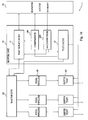
- Fig. 16 is a schematic overview of a buffer architecture 1, to which the teachings of the embodiments can be applied.
- the architecture comprises a random access memory (RAM) 50 for storing pixel blocks comprising, among others, color buffers.
- a buffer unit 10 comprises a decompressor 200 according to the present invention for decompressing compressed blocks fetched from the RAM 50. The decompressed or decoded blocks are temporarily stored in an associated tile cache 14 of the buffer unit 10.
- a compressor 100 according to the present invention is also provided in the buffer unit 10 for compressing pixel blocks present in the cache 14 for storage in the RAM 50.
- the buffer unit 10 also comprises a tile table cache 12.
- This table cache 12 stores header information associated with the pixel blocks but kept separately from the buffer data.
- the tile table entries typically contains flags signaling whether the associated pixel block is stored in uncompressed form or in a compressed form in the RAM 50.
- the flag preferably also signals the size of the compressed block, as different compressed blocks can have different total bit lengths. For example, a 2-bit flag can be used for signaling uncompressed block, compressed with compressed with 50 % of original size, compressed with 25 % of original size or fast-color-cleared.
- a rasterizer or rasterizing unit 20 is connected to the buffer unit 10 and performs the actual rasterization of pixels.
- the rasterizer 20 is connected to one or multiple pixel pipelines 30 that are employed for computing the depth and color of a pixel.
- Each pixel pipeline 30 is connected to a depth testing unit 40 responsible for discarding pixels that are occluded, i.e. having a larger depth value, by previously drawn geometry.
- the order of the pixel pipelines 30 and the depth testing units 40 can be interchanged from what is disclosed in Fig. 16 .
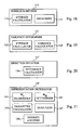
- Fig. 17 is a schematic block diagram of a compressor 100 according to an embodiment.
- the compressor 100 comprises a hierarchical organizer 110 for sub-sampling pixels of a pixel block to be compressed into pixel subblocks occupying the pixel positions in the block of these sub-sampled pixels.
- the organizer 110 comprises a subblock definer 111 for hierarchically defining a subblock in the pixel block based on the property values of the set of multiple pixels or hierarchically lower subblocks to be sub-sampled.
- the subblock definer 111 first investigates all non-overlapping sets of pixels, such as 2 ⁇ 2 pixels, in the block and investigates whether the property values of these pixels are homogenous enough to entitle them to be sub-sampled into a first level subblock. Once all 2 ⁇ 2 sets of adjacent pixels have been tested in a first round, the subblock definer 111 moves up one hierarchical level and investigates sets of first level subblocks, such as 2 ⁇ 2 adjacent subblocks. If these are deemed homogenous they are sub-sampled into a second level subblock. This procedure is repeated until all pixel and subblock sets have been tested.
- the definer 111 also generates a so-called tree code descriptive of the resulting hierarchical tree structure to thereby determine whether the block or any subblocks has children or if the node is a leaf.
- the compressed representation of the current block preferably comprises the tree code determined by the subblock definer 111.
- a value determiner 113 of the organizer 110 determines a respective property value for the subblocks defined by the subblock definer 111.
- the property value is determined based on at least a portion of the property values of the sub-sampled pixels or (hierarchically lower) subblocks, preferably as an average of these multiple sub-sampled property values.
- the block compressor 110 also comprises a prediction provider 120 for generating of predictions of property values for pixels and subblocks in the block.
- the prediction provider 120 comprises a variance determiner 121 arranged for determining, for a given subblock, a variance representation of property values of neighboring pixels and/or subblocks present in a first and a second prediction direction in the block relative the current subblock.
- This variance representation is compared to a variance threshold. If the determined variance measure is below the threshold, a first prediction determiner 123 becomes operated and determines the prediction based on weighted combination of neighboring property values in both prediction directions. In a preferred embodiment, this weighted combination is an average of the property values of the neighboring pixels/subblocks in the two prediction directions.
- a direction selector 127 of the prediction provider 120 selects a prediction direction of the first and second directions. This selection is preferably performed based on respective comparisons of the property values of the current subblock and the property values in the first direction and in the second direction. More preferably, the direction selector calculates an average of the neighboring property values in the first direction and an average of the values in the second prediction. These two averages are then compared to the current property value and the prediction direction, the average property value of which that is closest to the current value, is selected.
- the direction selector 127 preferably comprises a difference calculator 126 as is illustrated in the embodiment of Fig. 20 for calculating the two differences, which are then compared by the direction selector 127.
- a second prediction determiner 125 becomes operated if the variance measure is not smaller than the threshold and determines the property value prediction based on at least one neighboring property value in the prediction direction selected by the direction selector 127.
- the prediction could be determined based on the average of all neighboring pixels/subblocks in the selected direction, based on the average of a subset of the neighboring pixels/subblocks or based on only one neighboring pixel/subblock in the selected direction as previously described.
- the variance determiner 121 can determine a second variance representation of the property values of the neighboring pixels/subblocks in the selected prediction direction.
- the first prediction determiner 123 determines the predication based on an average of all the neighboring values in the relevant direction, possibly also including the neighboring property value in a third prediction direction. However, if the variance measure instead exceeds the threshold, the second prediction determiner 125 determines the prediction based on a single pixel/subblock in the case of a first level subblock or a further test is made to see whether the prediction of the current subblock should be based on a subset of the neighboring property values in the relevant direction or only based on a single value in the case of a second and higher level subblock.
- the prediction provider 120 also comprises a guiding bit provider 129 arranged for providing a guiding bit associated with the prediction direction selected by the direction selector 127.
- the direction selector 127 may be activated zero, one, two or three times for a second level subblock, implying that the guiding bit 129 can provide zero, one or multiple guiding bits for a subblock.
- These guiding bits 129 are stored in the compressed representation of the current block.
- the compressor 100 also comprises an error calculator 130 for calculating a prediction error for a current subblock based on the property value of the subblock and the provided prediction from the provider 120.
- the error is preferably a difference between the property value and the prediction.
- a representation determiner 140 processes the calculated prediction error to get an encoded error representation.
- the resulting compressed block comprises this encoded error representation for the current subblock and any guiding bit if employed.
- Fig. 18 is a block diagram illustrating an embodiment of the subblock definer 111 in Fig. 17 .
- the definer 111 comprises an average calculator 112 for calculating an average value of the property values of the pixels or subblocks to potentially be sub-sampled into a (higher level) subblock.
- An organizer 114 compares the respective absolute differences between the calculated value and the property values of the pixels/subblocks with a difference threshold. If all the absolute differences are below the threshold, the organizer 114 sub-samples the pixels/subblocks into a subblock of higher level in the tree structure. The organizer 114 also updates the tree code accordingly.
- the units 112 and 114 of the subblock definer 111 may be provided as software, hardware or a combination thereof.
- the units 112 and 114 may be implemented together in the subblock definer 111. Alternatively, a distributed implementation is also possible with some of the units provided elsewhere in the compressor.
- the difference threshold used by the organizer in order to determine whether to perform sub-sampling or not for a set of pixels/subblocks is preferably determined by a threshold determiner 115 of the hierarchical organizer 110.
- This determiner 115 preferably adjusts the threshold value depending on the hierarchical level of the tentative subblock.
- the threshold value used for testing the average of a set of pixels is preferably higher than the corresponding threshold used for testing the average of a set of subblocks as previously described.
- the threshold determiner 115 may also adjust the threshold depending on what type of property value to process. For instance, threshold values used in connection with luminance data are preferably comparatively lower than thresholds for chrominance data.
- the threshold value may also be adjusted based on an accumulated error for the current block.
- the block compressor 100 comprises an accumulation error determiner 160 comprising an error estimator 161.
- This error estimator 161 calculates an error value indicative of the error in representing the property values of the sub-sampled pixels/subblocks with the single property value calculated by the value determiner 113.
- An error updater 163 updates an associated accumulated error for the block to be compressed with the calculated error value from the estimator 161.
- the threshold determiner 115 can then adjust the difference threshold based on the updated accumulated error, generally by decreasing the threshold value if the accumulated error exceeds a given percentage of the maximum allowable accumulated error for the block.
- Fig. 19 is a schematic block diagram of an embodiment of the variance determiner 121 of the compressor in Fig. 17 .
- the determiner 121 preferably comprises an average calculator 122 for calculating an average value of relevant input property values for neighboring pixels and/or subblocks.
- a variance calculator 124 then calculates the variance parameter based on respective squared or absolute differences between the average value and the individual neighboring property values.
- the units 122 and 124 of the variance determiner 121 may be provided as software, hardware or a combination thereof.
- the units 122 and 124 may be implemented together in the variance determiner 121.
- a distributed implementation is also possible with some of the units provided elsewhere in the compressor.
- the block compressor 100 preferably also comprises a start selector 150.
- the start selector 150 selects a start property value for the block, where this value is equal to the property value of a selected pixel or subblock in the block.
- This pixel/subblock preferably has a predefined pixel position in the block and preferably occupies the upper left pixel.
- the compressed block representation comprises a representation of the start property value, preferably as an unquantized bit sequence.
- the prediction provider 110 is arranged for providing predictions for pixels and subblocks present in the same row and column as the start pixel/subblock, preferably the first row and column. For these pixels/subblocks, the respective predictions are selected to be equal to the property value of the pixel/subblock having the immediate preceding position towards the start pixel/subblock in the same row or column as the current pixel or subblock.
- the compressor 100 preferably also comprises a restart determiner 170 for selecting any restart property value for the block.
- the selector 170 preferably comprises an error comparator 171 for comparing the prediction error for a current pixel or subblock as determined by the error calculator 130 with a threshold error. If the prediction error exceeds the prediction error, the number of bits required for coding the error by the representation determiner 140 will be comparatively large, reducing the effectiveness of the block compression. In such a case, a restart selector 173 selects the current pixel or subblock to be a so-called restart pixel/subblock.
- an encoded representation of the property value preferably in the form a quantized version of the property value, is stored in the compressed block together with a representation of the pixel position of the pixel/subblock in the block.
- the units 110 to 173 of the block compressor 100 may be provided as software, hardware or a combination thereof.
- the units 110 to 173 may be implemented together in the compressor 100. Alternatively, a distributed implementation is also possible with some of the units provided elsewhere in the buffer architecture.
- Fig. 21 is a schematic block diagram of an embodiment of the representation determiner in the block compressor of Fig. 17 .
- This embodiment determines a quantization parameter, preferably an adaptive parameter, to use for quantizing the prediction errors calculated by the error calculator in the compressor.
- the determiner 140 comprises an error weight determiner for determining an error weight based on the accumulated error associated with the block and calculated by the error updater of the compressor.
- the determiner 141 reduces the error weight if the accumulated error exceeds a predefined percentage of the maximum allowable accumulated error for the block.
- a hierarchical weight determiner 143 determines a hierarchical weight that is dependent on whether the prediction error relates to a single pixel or a subblock.
- the weight value is reduced the higher up in the tree structure one comes, implying that the hierarchical weight for a pixel is larger than for a first level subblock, which in turn has a larger weight than a second level subblock, and so on.
- a parameter calculator 145 then calculates the quantization parameter for the current pixel/subblock based on the determined error and hierarchical weights.
- a quantizier 147 quantizes the prediction error with the quantization parameter, typically by dividing the error with the parameter following by rounding or shifting the bit sequence of the prediction error a number of steps to the right defined by the quantization parameter.
- the quantized prediction error is then entropy encoded by an entropy encoder 149 of the representation determiner 140.
- the resulting modified prediction error is encoded, preferably by a Golomb-Rice coder.
- the encoder 149 searches for an exponent value k employed to get a number 2 k , by which the modified prediction error is divided.
- An exhaustive search among all available values k can be conducted but generally a limited search among p - 4 ⁇ k ⁇ p , where p is the bit position of the most significant bit in the largest prediction error of the investigated group, is adequate.
- the value k leading to the most efficient coding, i.e. shortest compressed block representation is then selected and used.
- the encoder 149 divides the prediction errors by the number 2 k to get a quotient and a k -bit remainder. The remainder is then unary encoded according well known procedures.
- the encoded prediction error representation of a pixel then comprises the unary coded quotient, the remainder and the value k .
- the units 141 to 149 of the representation determiner 140 may be provided as software, hardware or a combination thereof.
- the units 141 to 149 may be implemented together in the representation determiner 140. Alternatively, a distributed implementation is also possible with some of the units provided elsewhere in the compressor.
- Fig. 22 is a schematic block diagram of an alternative embodiment of the representation determiner 140 of the block compressor.
- the resulting output (quantized) prediction error from the quantizer 144 is then input to an entropy encoder 146.
- the operation of this encoder 146 is similar to what has previously been described in connection with Fig. 21 .
- the units 142 to 146 of the representation determiner 140 may be provided as software, hardware or a combination thereof.
- the units 142 to 146 may be implemented together in the representation determiner 140. Alternatively, a distributed implementation is also possible with some of the units provided elsewhere in the compressor.
- Fig. 23 is a block diagram of an embodiment of a decompressor 200 for decompressing a compressed pixel block.
- the decompressor 200 comprises an error determiner 210 arranged for determining a prediction error of a pixel/subblock to be decoded. This prediction error is determined based on an encoded error representation assigned to the pixel/subblock and include din the compressed pixel block.
- the error determiner 210 preferably comprises a Golomb-Rice decoder (not illustrated) or another entropy decoder operating on the encoded prediction error representation in the compressed block.
- the decoder uses a unary coded quotient, a k -bit remainder and a value k of a pixel to calculate the prediction error as previously described.
- a prediction provider 220 is implemented in the decompressor 200 for providing a prediction of the property value of the subblock.
- the provider 220 comprises a variance determiner 221 arranged for calculating a variance representation of neighboring property values of at least one neighboring pixel/subblock in two prediction directions in the block relative the current subblock.
- a first prediction calculator 223 becomes operable for calculating the value prediction based on neighboring property values in both prediction directions.
- the operation of the calculator 223 is similar to the first prediction calculator of the block compressor in Fig. 17 .
- a direction selector 227 becomes active and selects a prediction direction based on a guiding bit associated with the current subblock.
- the hierarchical level of the subblock as determined through the tree code included in the compressed block and the number of guiding bits associated with the subblock defines which neighboring pixels/subblocks in the selected prediction direction to use by a second prediction calculator 225 for calculating the property value prediction.
- the second prediction calculator 225 could calculate the prediction to be based on i) the average of all neighboring pixels/subblocks in the relevant direction, ii) the average of a subset of the neighboring pixels/subblocks in the relevant direction, or iii) the property value of one neighboring pixel/sublock.
- a representation calculator 230 uses the prediction error from the error determiner 210 and the prediction from the provider 220 to calculate the property value of the subblock. This property value is then assigned by a value assigner 240 to the individual pixels present in the pixel block at the area occupied by the subblock that has now been decompressed.
- the decompressor 200 preferably also comprises a start provider 250.
- This start provider 250 is implemented for providing a property value of a start pixel/subblock in the block. This property value is preferably set equal to the start property value comprised in the compressed pixel block.
- the prediction provider 220 preferably provides the predictions for pixels/subblocks in the same row and column as the start pixel/subblock by setting the prediction to be equal to the property value of the next previous pixel/subblock in the row or column.
- a corresponding restart determiner 260 is arranged in the decompressor 200 for determining whether any restart pixel/subblock is present in the block.
- the determiner 260 comprises a restart identifier that investigates whether a restart bit included in the compressed block is set. If a restart value should be used, the identifier 261 uses a restart position identifier of the compressed block to identify the particular pixel position in the block that is regarded as restart pixel/subblocks.
- the block can comprise zero, one or multiple such restart pixels/subblocks.
- a restart provider 263 sets the property value of the restart pixel/subblock based on a representation of the restart value and included in the compressed block.
- the provider 263 unqantized the value from the block by extending it into a target number of bits and then assigns it to the identified pixel/subblock.
- the units 210 to 260 of the decompressor 200 may be provided as software, hardware or a combination thereof.
- the units 210 to 260 may be implemented together in the decompressor 200. Alternatively, a distributed implementation is also possible with some of the units provided elsewhere in the buffer architecture.
- Fig. 24 is a schematic block diagram of an embodiment of the variance determiner 221 of the decompressor in Fig. 23 .
- the determiner 221 comprises an average calculator 222 for determining an average value of the input neighboring pixels or subblocks.
- the variance measure is then calculated by a variance calculator 224 based on respective absolute differences between the average and the respective neighboring property values.
- the units 222 and 224 of the variance determiner 221 may be provided as software, hardware or a combination thereof.
- the units 222 and 224 may be implemented together in the variance determiner 221. Alternatively, a distributed implementation is also possible with some of the units provided elsewhere in the decompressor.
Claims (18)
- Procédé de compression d'un bloc (300) de multiples pixels (310) ayant chacun une valeur de propriété respective, ledit procédé comprenant les étapes consistant à :- définir hiérarchiquement un sous-bloc (320, 330) dans ledit bloc (300) sur la base des valeurs de propriété d'un sous-ensemble desdits multiples pixels (310) ou d'un ensemble de sous-blocs hiérarchiquement inférieurs (320) dans ledit bloc (300) ;- déterminer une valeur de propriété pour ledit sous-bloc (320, 330) sur la base d'au moins une partie desdites valeurs de propriété dudit sous-ensemble desdits multiples pixels (310) ou dudit ensemble de sous-blocs hiérarchiquement inférieurs (320) ;- fournir une prédiction de ladite valeur de propriété déterminée en :a) déterminant une première représentation de variance de valeur(s) de propriété d'au moins un pixel voisin ou sous-bloc dans une première direction de prédiction dans ledit bloc (300) et de valeur(s) de propriété d'au moins un pixel voisin ou sous-bloc dans une deuxième direction de prédiction dans ledit bloc (300) ;b) déterminant ladite prédiction sur la base d'une combinaison pondérée d'au moins une valeur de propriété dudit au moins un pixel voisin ou sous-bloc dans ladite première direction de prédiction et d'au moins une valeur de propriété dudit au moins un pixel voisin ou sous-bloc dans ladite deuxième direction de prédiction si ladite première représentation de variance est inférieure à un premier seuil de variance ;c) sélectionnant une direction de prédiction desdites première et deuxième directions de prédiction si ladite première représentation de variance n'est pas inférieure audit premier seuil de variance ;d) déterminant ladite prédiction pour qu'elle soit basée sur au moins une valeur de propriété dudit au moins un pixel voisin ou sous-bloc dans ladite direction de prédiction sélectionnée si ladite première représentation de variance n'est pas inférieure audit premier seuil de variance ;e) fournissant un premier bit de guidage (450) associé à ladite direction de prédiction sélectionnée si ladite première représentation de variance n'est pas inférieure audit premier seuil de variance ;- calculer une erreur de prédiction sur la base de ladite valeur de propriété déterminée et de ladite prédiction fournie ; et- déterminer une représentation encodée (460) de ladite erreur de prédiction, dans lequel une représentation compressée (400) dudit bloc (300) comprend ladite représentation encodée (460) et ledit premier bit de guidage (450) optionnel.
- Procédé selon la revendication 1, dans lequel ladite étape de définition hiérarchique consiste à :- calculer une valeur moyenne desdites valeurs de propriété dudit sous-ensemble desdits multiples pixels (310) ou dudit ensemble de sous-blocs hiérarchiquement inférieurs (320) ; et- organiser ledit sous-ensemble desdits multiples pixels (310) ou ledit ensemble de sous-blocs hiérarchiquement inférieurs (320) en ledit sous-bloc (320, 330) si les différences absolues respectives entre ladite valeur moyenne et lesdites valeurs de propriété dudit sous-ensemble desdits multiples pixels (310) ou dudit ensemble de sous-blocs hiérarchiquement inférieurs (320) sont au-dessous d'un seuil de différence.
- Procédé selon la revendication 2, consistant en outre à déterminer ledit seuil de différence selon que ladite étape d'organisation consiste à organiser ledit sous-ensemble desdits multiples pixels (310) en ledit sous-bloc (320) ou à organiser ledit ensemble de sous-blocs hiérarchiquement inférieurs (320) en ledit sous-bloc (330).
- Procédé selon la revendication 2 ou 3, comprenant en outre les étapes consistant à :- estimer une valeur d'erreur indicative d'une erreur lors de la représentation desdites valeurs de propriété dudit sous-ensemble de multiples pixels (310) ou dudit ensemble de sous-blocs hiérarchiquement inférieurs (320) par ladite valeur de propriété déterminée ;- mettre à jour, sur la base de ladite valeur d'erreur, une erreur accumulée associée audit bloc (300) et indicative d'erreurs d'approximation lors de la représentation dudit bloc (300) par ladite représentation compressée (400) dudit bloc (300) ; et- déterminer ledit seuil de différence sur la base de ladite erreur accumulée mise à jour.
- Procédé selon l'une quelconque des revendications 1 à 4, dans lequel ladite étape de sélection c) comprend les étapes consistant à :- calculer une première différence entre ladite valeur de propriété déterminée et une représentation desdites valeurs de propriété dudit au moins un bloc de pixels voisins ou sous-bloc dans ladite première direction de prédiction ;- calculer une deuxième différence entre ladite valeur de propriété déterminée et une représentation desdites valeurs de propriété dudit au moins un bloc de pixels voisins ou sous-bloc dans ladite deuxième direction de prédiction ; et- sélectionner ladite direction de prédiction sur la base d'une comparaison de ladite première différence et de ladite deuxième différence.
- Procédé selon l'une quelconque des revendications 1 à 5, dans lequel ladite étape de détermination d) comprend les étapes consistant à :- déterminer une deuxième représentation de variance desdites valeurs de propriété desdits pixels voisins ou des sous-blocs dans ladite direction de prédiction sélectionnée ;- déterminer ladite prédiction sur la base d'une moyenne desdites valeurs de propriété desdits pixels voisins ou des sous-blocs dans ladite direction de prédiction sélectionnée si ladite deuxième représentation de variance est inférieure à un deuxième seuil de variance ;- déterminer ladite prédiction sur la base d'un sous-ensemble desdites valeurs de propriété desdits pixels voisins ou des sous-blocs dans ladite direction de prédiction sélectionnée si ladite deuxième représentation de variance n'est pas inférieure audit deuxième seuil de variance ; et- fournir un deuxième bit de guidage (450) associé audit sous-ensemble desdites valeurs de propriété si ladite deuxième représentation de variance n'est pas inférieure audit deuxième seuil de variance, dans lequel ladite représentation compressée (400) dudit bloc (300) comprend ledit deuxième bit de guidage (450) optionnel.
- Procédé selon l'une quelconque des revendications 1 à 6, dans lequel ladite étape consistant à déterminer ladite représentation encodée (360) de ladite erreur de prédiction comprend les étapes consistant à :- déterminer un coefficient de pondération d'erreur sur la base d'une erreur accumulée associée audit bloc (300) et représentative d'erreurs d'approximation lors de la représentation dudit bloc (300) par ladite représentation compressée (400) dudit bloc (300) ;- déterminer un coefficient de pondération hiérarchique selon que ladite étape de définition hiérarchique consiste à définir ledit sous-ensemble desdits multiples pixels (310) dans ledit sous-bloc (320) ou à définir ledit ensemble de sous-blocs hiérarchiquement inférieurs (320) dans ledit sous-bloc (330) ;- calculer un paramètre de quantification sur la base dudit coefficient de pondération d'erreur, dudit coefficient de pondération hiérarchique et d'un paramètre de quantification de défaut ;- calculer une erreur de prédiction quantifiée sur la base de ladite erreur de prédiction et dudit paramètre de quantification ; et- encoder par entropie ladite erreur de prédiction quantifiée pour former ladite représentation encodée (460) de ladite erreur de prédiction.
- Procédé de décompression d'un bloc de pixels compressé (400), ledit procédé comprenant les étapes consistant à :- déterminer, pour un sous-bloc de pixels (320, 330) dudit bloc (300), une erreur de prédiction sur la base d'une représentation d'erreur encodée (460) associée audit sous-bloc (320, 330) et comprise dans ledit bloc de pixels compressé (400) ;- fournir une prédiction d'une valeur de propriété dudit sous-bloc (320, 330) en :a) déterminant une première représentation de variance de valeur(s) de propriété d'au moins un pixel voisin ou sous-bloc dans une première direction de prédiction dans ledit bloc (300) et de valeur(s) de propriété d'au moins un pixel voisin ou sous-bloc dans une deuxième direction de prédiction dans ledit bloc (300) ;b) calculant ladite prédiction sur la base d'une combinaison pondérée d'au moins une valeur de propriété dudit au moins un pixel voisin ou sous-bloc dans ladite première direction de prédiction et d'au moins une valeur de propriété dudit au moins un pixel voisin ou sous-bloc dans ladite deuxième direction de prédiction si ladite première représentation de variance est inférieure à un premier seuil de variance ;c) sélectionnant une direction de prédiction de ladite première direction de prédiction et de ladite deuxième direction de prédiction sur la base d'un premier bit de guidage (450) associé audit sous-bloc (320, 330) et compris dans ledit bloc de pixels compressé (400) si ladite première représentation de variance n'est pas inférieure audit premier seuil de variance ;d) calculant ladite prédiction pour qu'elle soit basée sur au moins une valeur de propriété dudit au moins un pixel voisin ou sous-bloc dans ladite direction de prédiction sélectionnée si ladite première représentation de variance n'est pas inférieure audit premier seuil de variance ;- calculer une représentation de ladite valeur de propriété dudit sous-bloc (320, 330) sur la base de ladite erreur de prédiction et de ladite prédiction ; et- attribuer ladite représentation desdites valeurs de propriété aux multiples pixels (310) dans ledit bloc (300) organisés en ledit sous-bloc (320, 330).
- Procédé selon la revendication 8, dans lequel ladite étape de calcul d) comprend les étapes consistant à :- déterminer une deuxième représentation de variance desdites valeurs de propriété desdits pixels voisins ou des sous-blocs dans ladite direction de prédiction sélectionnée ;- calculer ladite prédiction sur la base d'une moyenne desdites valeurs de propriété desdits pixels voisins ou sous-blocs dans ladite direction de prédiction sélectionnée si ladite deuxième représentation de variance est inférieure à un deuxième seuil de variance ;- identifier un sous-ensemble desdites valeurs de propriété desdits pixels voisins ou sous-blocs dans ladite direction de prédiction sélectionnée sur la base d'un deuxième bit de guidage (450) associé audit sous-bloc et compris dans ledit bloc de pixels compressé (400) si ladite deuxième représentation de variance n'est pas inférieure à un deuxième seuil de variance ; et- calculer ladite prédiction sur la base dudit sous-ensemble identifié desdites valeurs de propriété si ladite deuxième représentation de variance n'est pas inférieure audit deuxième seuil de variance.
- Procédé selon l'une quelconque des revendications 1 à 9, dans lequel ladite étape de détermination a) comprend les étapes consistant à :- calculer une valeur moyenne desdites valeurs de propriété desdits pixels voisins ou sous-blocs ; et- calculer ladite représentation de variance sur la base des différences élevées au carré respectives entre ladite valeur moyenne et lesdites valeurs de propriété desdits pixels voisins ou sous-blocs.
- Dispositif de compression de bloc (100) pour compresser un bloc (300) de multiples pixels (310) ayant chacun une valeur de propriété respective, ledit dispositif de compression de bloc (100) comprenant :- un dispositif de définition de sous-bloc (111) pour définir hiérarchiquement un sous-bloc (320, 330) dans ledit bloc (300) sur la base de valeurs de propriété d'un sous-ensemble desdits multiples pixels (310) ou d'un ensemble de sous-blocs hiérarchiquement inférieurs (320) dans ledit bloc (300) ;- un dispositif de détermination de valeur (113) pour déterminer une valeur de propriété pour ledit sous-bloc (320, 330) sur la base d'au moins une partie desdites valeurs de propriété dudit sous-ensemble desdits multiples pixels (310) ou dudit ensemble de sous-blocs hiérarchiquement inférieurs (320) ;- un dispositif de fourniture de prédiction (120) pour fournir une prédiction de ladite valeur de propriété déterminée, ledit dispositif de fourniture de prédiction (120) comprenant :- un dispositif de détermination de variance (121) pour déterminer une première représentation de variance de valeur(s) de propriété d'au moins un pixel voisin ou sous-bloc dans une première direction de prédiction dans ledit bloc (300) et de valeur(s) de propriété d'au moins un pixel voisin ou sous-bloc dans une deuxième direction de prédiction dans ledit bloc (300) ;- un premier dispositif de détermination de prédiction (123) conçu pour fonctionner si ladite première représentation de variance est inférieure à un premier seuil de variance et agencé pour déterminer ladite prédiction sur la base d'une combinaison pondérée d'au moins une valeur de propriété dudit au moins un pixel voisin ou sous-bloc dans ladite première direction de prédiction et d'au moins une valeur de propriété dudit au moins un pixel voisin ou sous-bloc dans ladite deuxième direction de prédiction ;- un dispositif de sélection de direction (127) conçu pour fonctionner si ladite première représentation de variance n'est pas inférieure audit premier seuil de variance et agencé pour sélectionner une direction de prédiction desdites première et deuxième directions de prédiction ;- un deuxième dispositif de détermination de prédiction (125) conçu pour fonctionner si ladite première représentation de variance n'est pas inférieure audit premier seuil de variance et agencé pour déterminer ladite prédiction pour qu'elle soit basée sur au moins une valeur de propriété dudit au moins un pixel voisin ou sous-bloc dans ladite direction de prédiction sélectionnée ;- un dispositif de fourniture de bit de guidage (129) conçu pour fonctionner si ladite première représentation de variance n'est pas inférieure audit premier seuil de variance et agencé pour fournir un premier bit de guidage (450) associé à ladite direction de prédiction sélectionnée ;- un dispositif de calcul d'erreur (130) pour calculer une erreur de prédiction sur la base de ladite valeur de propriété déterminée et de ladite prédiction fournie ; et- un dispositif de détermination de représentation (140) pour déterminer une représentation encodée (460) de ladite erreur de prédiction, dans lequel une représentation compressée (400) dudit bloc (300) comprend ladite représentation encodée (460) et ledit premier bit de guidage (450) optionnel.
- Dispositif de compression selon la revendication 11, dans lequel ledit dispositif de définition de sous-bloc (111) comprend :- un dispositif de calcul de moyenne (112) pour calculer une valeur moyenne desdites valeurs de propriété dudit sous-ensemble desdits multiples pixels (310) ou dudit ensemble de sous-blocs hiérarchiquement inférieurs (320) ; et- un dispositif d'organisation (114) pour organiser ledit sous-ensemble desdits multiples pixels (310) ou ledit ensemble de sous-blocs hiérarchiquement inférieurs (320) en ledit sous-bloc (320, 330) si les différences absolues respectives entre ladite valeur moyenne et lesdites valeurs de propriété dudit sous-ensemble desdits multiples pixels (310) ou dudit ensemble de sous-blocs hiérarchiquement inférieurs (320) sont au-dessous d'un seuil de différence.
- Dispositif de compression selon la revendication 12, comprenant en outre :- un dispositif d'estimation d'erreur (161) pour estimer une valeur d'erreur indicative d'une erreur lors de la représentation desdites valeurs de propriété dudit sous-ensemble de multiples pixels (310) ou dudit ensemble de sous-blocs hiérarchiquement inférieurs (320) par ladite valeur de propriété déterminée ;- un dispositif de mise à jour d'erreur (163) pour mettre à jour, sur la base de ladite valeur d'erreur, une erreur accumulée associée audit bloc (300) et indicative d'erreurs d'approximation lors de la représentation dudit bloc (300) par ladite représentation compressée (400) dudit bloc (300) ; et- un dispositif de détermination de seuil (115) pour déterminer ledit seuil de différence sur la base de ladite erreur accumulée mise à jour.
- Dispositif de compression selon l'une quelconque des revendications 11 à 13, dans lequel ledit dispositif de sélection de direction (127) comprend un dispositif de calcul de différence (126) pour i) calculer une première différence entre ladite valeur de propriété déterminée et une représentation desdites valeurs de propriété dudit au moins un bloc de pixels voisins ou sous-bloc dans ladite première direction de prédiction, et ii) calculer une deuxième différence entre ladite valeur de propriété déterminée et une représentation desdites valeurs de propriété dudit au moins un bloc de pixels voisins ou sous-bloc dans ladite deuxième direction de prédiction, et dans lequel ledit dispositif de sélection de direction (127) est agencé pour sélectionner ladite direction de prédiction sur la base d'une comparaison de ladite première différence et de ladite deuxième différence.
- Dispositif de compression selon l'une quelconque des revendications 11 à 14, dans lequel
ledit dispositif de détermination de variance (121) est agencé pour déterminer une deuxième représentation de variance desdites valeurs de propriété desdits pixels voisins ou sous-blocs dans ladite direction de prédiction sélectionnée ;
ledit premier dispositif de détermination de prédiction (123) est conçu pour fonctionner si ladite deuxième représentation de variance est inférieure à un deuxième seuil de variance et est agencé pour déterminer ladite prédiction sur la base d'une moyenne desdites valeurs de propriété desdits pixels voisins ou sous-blocs dans ladite direction de prédiction sélectionnée ;
ledit deuxième dispositif de détermination de prédiction (125) est conçu pour fonctionner si ladite deuxième représentation de variance n'est pas inférieure audit deuxième seuil de variance et est agencé pour déterminer ladite prédiction sur la base d'un sous-ensemble desdites valeurs de propriété desdits pixels voisins ou sous-blocs dans ladite direction de prédiction sélectionnée ; et
ledit dispositif de fourniture de bit de guidage (129) est conçu pour fonctionner si ladite deuxième représentation de variance n'est pas inférieure audit deuxième seuil de variance et est agencé pour fournir un deuxième bit de guidage (450) associé audit sous-ensemble desdites valeurs de propriété, dans lequel ladite représentation compressée (400) dudit bloc (300) comprend ledit deuxième bit de guidage (450) optionnel. - Dispositif de décompression de bloc (200) pour décompresser un bloc de pixels compressé (400), ledit dispositif de décompression de bloc (200) comprenant :- un dispositif de détermination d'erreur (210) pour déterminer, pour un sous-bloc de pixels (320, 330) dudit bloc (300), une erreur de prédiction sur la base d'une représentation d'erreur encodée (460) associée audit sous-bloc (320, 330) et comprise dans ledit bloc de pixels compressé (400) ;- un dispositif de fourniture de prédiction (220) pour fournir une prédiction d'une valeur de propriété dudit sous-bloc (320, 330) et comprenant :- un dispositif de détermination de variance (221) pour déterminer une première représentation de variance de valeur(s) de propriété d'au moins un pixel voisin ou sous-bloc dans une première direction de prédiction dans ledit bloc (300) et de valeur(s) de propriété d'au moins un pixel voisin ou sous-bloc dans une deuxième direction de prédiction dans ledit bloc (300) ;- un premier dispositif de calcul de prédiction (223) conçu pour fonctionner si ladite première représentation de variance est inférieure à un premier seuil de variance et agencé pour calculer ladite prédiction sur la base d'une combinaison pondérée d'au moins une valeur de propriété dudit au moins un pixel voisin ou sous-bloc dans ladite première direction de prédiction et d'au moins une valeur de propriété dudit au moins un pixel voisin ou sous-bloc dans ladite deuxième direction de prédiction ;- un dispositif de sélection de direction (227) conçu pour fonctionner si ladite première représentation de variance n'est pas inférieure audit premier seuil de variance et agencé pour sélectionner une direction de prédiction de ladite première direction de prédiction et de ladite deuxième direction de prédiction sur la base d'un premier bit de guidage (450) associé audit sous-bloc (320, 330) et compris dans ledit bloc de pixels compressé (400) ;- un deuxième dispositif de calcul de prédiction (225) conçu pour fonctionner si ladite première représentation de variance n'est pas inférieure audit premier seuil de variance et agencé pour calculer ladite prédiction pour qu'elle soit basée sur au moins une valeur de propriété dudit au moins un pixel voisin ou sous-bloc dans ladite direction de prédiction sélectionnée ;- un dispositif de calcul de représentation (230) pour calculer une représentation de ladite valeur de propriété dudit sous-bloc (320, 330) sur la base de ladite erreur de prédiction et de ladite prédiction ; et- un dispositif d'attribution de valeur (240) pour attribuer ladite représentation desdites valeurs de propriété aux multiples pixels (310) dans ledit bloc (300) organisés en ledit sous-bloc (320, 330).
- Dispositif de décompression selon la revendication 16, dans lequel ledit dispositif de détermination de variance (221) comprend :- un dispositif de calcul de moyenne (222) pour calculer une valeur moyenne desdites valeurs de propriété desdits pixels voisins ou sous-blocs ; et- un dispositif de calcul de variance (224) pour calculer ladite représentation de variance sur la base des différences élevées au carré respectives entre ladite valeur moyenne et lesdites valeurs de propriété desdits pixels voisins ou sous-blocs.
- Dispositif de décompression selon la revendication 16 ou 17, dans lequel
ledit dispositif de détermination de variance (221) est agencé pour déterminer une deuxième représentation de variance desdites valeurs de propriété desdits pixels voisins ou sous-blocs dans ladite direction de prédiction sélectionnée ;
ledit premier dispositif de calcul de prédiction (223) est conçu pour fonctionner si ladite deuxième représentation de variance est inférieure à un deuxième seuil de variance et est agencé pour calculer ladite prédiction sur la base d'une moyenne desdites valeurs de propriété desdits pixels voisins ou sous-blocs dans ladite direction de prédiction sélectionnée ;
ledit dispositif de sélection de direction (227) est conçu pour fonctionner si ladite deuxième représentation de variance n'est pas inférieure à un deuxième seuil de variance et est agencé pour identifier un sous-ensemble desdites valeurs de propriété desdits pixels voisins ou sous-blocs dans ladite direction de prédiction sélectionnée sur la base d'un deuxième bit de guidage (450) associé audit sous-bloc (320, 330) et compris dans ledit bloc de pixels compressé (400) ; et
ledit deuxième dispositif de calcul de prédiction (225) est conçu pour fonctionner si ladite deuxième représentation de variance n'est pas inférieure audit deuxième seuil de variance et est agencé pour calculer ladite prédiction sur la base dudit sous-ensemble identifié desdites valeurs de propriété.
Priority Applications (4)
| Application Number | Priority Date | Filing Date | Title |
|---|---|---|---|
| EP08164269A EP2081155B1 (fr) | 2008-01-21 | 2008-09-12 | Traitement d'image à base de prédiction |
| US12/863,727 US8107753B2 (en) | 2008-01-21 | 2009-01-19 | Prediction-based image processing |
| PCT/EP2009/050540 WO2009092681A1 (fr) | 2008-01-21 | 2009-01-19 | Traitement d'image selon une prédiction |
| CN200980102694.7A CN101925926B (zh) | 2008-01-21 | 2009-01-19 | 基于预测的图像处理 |
Applications Claiming Priority (5)
| Application Number | Priority Date | Filing Date | Title |
|---|---|---|---|
| US2239708P | 2008-01-21 | 2008-01-21 | |
| EP2008055520 | 2008-05-06 | ||
| PCT/EP2008/056288 WO2009092455A2 (fr) | 2008-01-21 | 2008-05-21 | Traitement d'image à base de prédiction |
| US5626508P | 2008-05-27 | 2008-05-27 | |
| EP08164269A EP2081155B1 (fr) | 2008-01-21 | 2008-09-12 | Traitement d'image à base de prédiction |
Publications (2)
| Publication Number | Publication Date |
|---|---|
| EP2081155A1 EP2081155A1 (fr) | 2009-07-22 |
| EP2081155B1 true EP2081155B1 (fr) | 2011-11-16 |
Family
ID=43587582
Family Applications (1)
| Application Number | Title | Priority Date | Filing Date |
|---|---|---|---|
| EP08164269A Not-in-force EP2081155B1 (fr) | 2008-01-21 | 2008-09-12 | Traitement d'image à base de prédiction |
Country Status (4)
| Country | Link |
|---|---|
| US (1) | US8107753B2 (fr) |
| EP (1) | EP2081155B1 (fr) |
| CN (1) | CN101925926B (fr) |
| WO (1) | WO2009092681A1 (fr) |
Families Citing this family (21)
| Publication number | Priority date | Publication date | Assignee | Title |
|---|---|---|---|---|
| US8964851B2 (en) | 2009-06-09 | 2015-02-24 | Sony Corporation | Dual-mode compression of images and videos for reliable real-time transmission |
| US8457425B2 (en) | 2009-06-09 | 2013-06-04 | Sony Corporation | Embedded graphics coding for images with sparse histograms |
| US8285062B2 (en) | 2009-08-05 | 2012-10-09 | Sony Corporation | Method for improving the performance of embedded graphics coding |
| CN102098519B (zh) * | 2009-12-09 | 2013-04-17 | 浙江大学 | 视频编码方法、解码方法、编码及解码装置 |
| US8559741B2 (en) * | 2010-06-02 | 2013-10-15 | Altek Corporation | Lossless image compression method |
| KR20120025111A (ko) * | 2010-09-07 | 2012-03-15 | 에스케이 텔레콤주식회사 | 참조 화소들의 특성을 이용하여 예측모드 정보의 전송을 생략할 수 있는 화면 내 예측 부호화/복호화 장치 및 그 방법 |
| GB2486726B (en) * | 2010-12-23 | 2017-11-29 | British Broadcasting Corp | Compression of pictures |
| JP5875236B2 (ja) * | 2011-03-09 | 2016-03-02 | キヤノン株式会社 | 画像符号化装置、画像符号化方法及びプログラム、画像復号装置、画像復号方法及びプログラム |
| US20140050414A1 (en) * | 2011-04-29 | 2014-02-20 | Telefonaktiebolaget L M Ericsson (Publ) | Encoder, Decoder and Methods Thereof for Texture Compression |
| CN107181962B (zh) * | 2011-10-07 | 2020-03-27 | 英迪股份有限公司 | 对当前块的帧内预测模式进行解码的方法 |
| US20150172576A1 (en) * | 2013-12-05 | 2015-06-18 | Aselsan Elektronik Sanayi Ve Ticaret Anonim Sirketi | Real time dynamic bad pixel restoration method |
| US9224030B2 (en) * | 2014-01-10 | 2015-12-29 | Qualcomm Incorporated | Sensor identification |
| US10104388B2 (en) * | 2014-06-30 | 2018-10-16 | Sony Corporation | Video processing system with high dynamic range sensor mechanism and method of operation thereof |
| KR102332782B1 (ko) * | 2014-12-15 | 2021-11-30 | 삼성전자주식회사 | 시각 특성을 고려한 영상 데이터 압축 |
| KR101724555B1 (ko) * | 2014-12-22 | 2017-04-18 | 삼성전자주식회사 | 부호화 방법 및 장치와 복호화 방법 및 장치 |
| US9460365B1 (en) * | 2015-03-24 | 2016-10-04 | Intel Corporation | Clustered palette compression |
| US20210211699A1 (en) * | 2016-02-16 | 2021-07-08 | Samsung Electronics Co., Ltd. | Adaptive block partitioning method and apparatus |
| KR102412007B1 (ko) * | 2017-07-20 | 2022-06-22 | 삼성전자주식회사 | 전자 장치 및 전자 장치에서 하이 다이나믹 레인지 이미지 데이터를 압축하는 방법 |
| KR102463720B1 (ko) * | 2017-12-18 | 2022-11-07 | 현대자동차주식회사 | 차량의 경로 생성 시스템 및 방법 |
| US11166048B2 (en) * | 2018-10-02 | 2021-11-02 | Tencent America LLC | Method and apparatus for video coding |
| GB2593523B (en) * | 2020-03-26 | 2023-06-14 | Imagination Tech Ltd | Image data compression |
Family Cites Families (7)
| Publication number | Priority date | Publication date | Assignee | Title |
|---|---|---|---|---|
| JP3169783B2 (ja) * | 1995-02-15 | 2001-05-28 | 日本電気株式会社 | 動画像の符号化・復号システム |
| US5682152A (en) * | 1996-03-19 | 1997-10-28 | Johnson-Grace Company | Data compression using adaptive bit allocation and hybrid lossless entropy encoding |
| US6246799B1 (en) * | 1996-09-04 | 2001-06-12 | Sony Corporation | Image compression encoder and image compression encoding method |
| EP0940994B1 (fr) * | 1998-03-06 | 2014-04-16 | Canon Kabushiki Kaisha | Appareil et méthode de traitement d'image, et support d'enregistrement stockant des étapes mettant en oeuvre cette méthode |
| US6654503B1 (en) * | 2000-04-28 | 2003-11-25 | Sun Microsystems, Inc. | Block-based, adaptive, lossless image coder |
| US7079579B2 (en) * | 2000-07-13 | 2006-07-18 | Samsung Electronics Co., Ltd. | Block matching processor and method for block matching motion estimation in video compression |
| JP4697967B2 (ja) * | 2006-03-02 | 2011-06-08 | キヤノン株式会社 | 画像符号化装置及びその制御方法 |
-
2008
- 2008-09-12 EP EP08164269A patent/EP2081155B1/fr not_active Not-in-force
-
2009
- 2009-01-19 WO PCT/EP2009/050540 patent/WO2009092681A1/fr active Application Filing
- 2009-01-19 US US12/863,727 patent/US8107753B2/en not_active Expired - Fee Related
- 2009-01-19 CN CN200980102694.7A patent/CN101925926B/zh not_active Expired - Fee Related
Also Published As
| Publication number | Publication date |
|---|---|
| EP2081155A1 (fr) | 2009-07-22 |
| US20110033127A1 (en) | 2011-02-10 |
| CN101925926A (zh) | 2010-12-22 |
| CN101925926B (zh) | 2013-05-01 |
| US8107753B2 (en) | 2012-01-31 |
| WO2009092681A1 (fr) | 2009-07-30 |
Similar Documents
| Publication | Publication Date | Title |
|---|---|---|
| EP2081155B1 (fr) | Traitement d'image à base de prédiction | |
| US8331664B2 (en) | Prediction-based image processing | |
| EP2235953B1 (fr) | Traitement d'image à base de prédiction | |
| US8396309B2 (en) | Index-based pixel block processing | |
| US8311353B2 (en) | Prediction-based image processing | |
| US8335385B2 (en) | Pixel block processing | |
| CN106254871B (zh) | 对图像内容的编码单元进行编码或解码的方法与装置 | |
| EP2005393B1 (fr) | Traitement d'image de haute qualité | |
| KR100819597B1 (ko) | 멀티모드 알파 이미지 처리 방법 및 장치 | |
| EP1697900B1 (fr) | Traitement d'image multi-mode | |
| EP2320380A1 (fr) | Traitement d'images multimodal | |
| US20140192866A1 (en) | Data Remapping for Predictive Video Coding | |
| US20160337668A1 (en) | Method and apparatus for encoding image data and method and apparatus for decoding image data | |
| US20130009977A1 (en) | Multi-Mode Processing of Texture Blocks | |
| US10930020B2 (en) | Texture compression using a neural network | |
| Rasmusson et al. | Error-bounded lossy compression of floating-point color buffers using quadtree decomposition | |
| Le Pendu et al. | Template based inter-layer prediction for high dynamic range scalable compression | |
| Naaz et al. | Implementation of hybrid algorithm for image compression and decompression | |
| CN113412618B (zh) | 用于编码和解码表示至少一个图像的数据流的方法和设备 | |
| TW201531089A (zh) | 將影像資料編碼之方法及裝置,以及將影像資料解碼之方法及裝置 | |
| US8238680B2 (en) | Image compression method with variable quantization parameters and variable coding parameters |
Legal Events
| Date | Code | Title | Description |
|---|---|---|---|
| PUAI | Public reference made under article 153(3) epc to a published international application that has entered the european phase |
Free format text: ORIGINAL CODE: 0009012 |
|
| AK | Designated contracting states |
Kind code of ref document: A1 Designated state(s): AT BE BG CH CY CZ DE DK EE ES FI FR GB GR HR HU IE IS IT LI LT LU LV MC MT NL NO PL PT RO SE SI SK TR |
|
| AX | Request for extension of the european patent |
Extension state: AL BA MK RS |
|
| 17P | Request for examination filed |
Effective date: 20100122 |
|
| AKX | Designation fees paid |
Designated state(s): AT BE BG CH CY CZ DE DK EE ES FI FR GB GR HR HU IE IS IT LI LT LU LV MC MT NL NO PL PT RO SE SI SK TR |
|
| GRAP | Despatch of communication of intention to grant a patent |
Free format text: ORIGINAL CODE: EPIDOSNIGR1 |
|
| GRAS | Grant fee paid |
Free format text: ORIGINAL CODE: EPIDOSNIGR3 |
|
| GRAA | (expected) grant |
Free format text: ORIGINAL CODE: 0009210 |
|
| AK | Designated contracting states |
Kind code of ref document: B1 Designated state(s): AT BE BG CH CY CZ DE DK EE ES FI FR GB GR HR HU IE IS IT LI LT LU LV MC MT NL NO PL PT RO SE SI SK TR |
|
| REG | Reference to a national code |
Ref country code: GB Ref legal event code: FG4D |
|
| REG | Reference to a national code |
Ref country code: CH Ref legal event code: EP |
|
| REG | Reference to a national code |
Ref country code: IE Ref legal event code: FG4D |
|
| REG | Reference to a national code |
Ref country code: DE Ref legal event code: R096 Ref document number: 602008011388 Country of ref document: DE Effective date: 20120126 |
|
| REG | Reference to a national code |
Ref country code: NL Ref legal event code: VDEP Effective date: 20111116 |
|
| LTIE | Lt: invalidation of european patent or patent extension |
Effective date: 20111116 |
|
| PG25 | Lapsed in a contracting state [announced via postgrant information from national office to epo] |
Ref country code: NO Free format text: LAPSE BECAUSE OF FAILURE TO SUBMIT A TRANSLATION OF THE DESCRIPTION OR TO PAY THE FEE WITHIN THE PRESCRIBED TIME-LIMIT Effective date: 20120216 Ref country code: IS Free format text: LAPSE BECAUSE OF FAILURE TO SUBMIT A TRANSLATION OF THE DESCRIPTION OR TO PAY THE FEE WITHIN THE PRESCRIBED TIME-LIMIT Effective date: 20120316 Ref country code: LT Free format text: LAPSE BECAUSE OF FAILURE TO SUBMIT A TRANSLATION OF THE DESCRIPTION OR TO PAY THE FEE WITHIN THE PRESCRIBED TIME-LIMIT Effective date: 20111116 |
|
| PG25 | Lapsed in a contracting state [announced via postgrant information from national office to epo] |
Ref country code: NL Free format text: LAPSE BECAUSE OF FAILURE TO SUBMIT A TRANSLATION OF THE DESCRIPTION OR TO PAY THE FEE WITHIN THE PRESCRIBED TIME-LIMIT Effective date: 20111116 Ref country code: SI Free format text: LAPSE BECAUSE OF FAILURE TO SUBMIT A TRANSLATION OF THE DESCRIPTION OR TO PAY THE FEE WITHIN THE PRESCRIBED TIME-LIMIT Effective date: 20111116 Ref country code: PT Free format text: LAPSE BECAUSE OF FAILURE TO SUBMIT A TRANSLATION OF THE DESCRIPTION OR TO PAY THE FEE WITHIN THE PRESCRIBED TIME-LIMIT Effective date: 20120316 Ref country code: LV Free format text: LAPSE BECAUSE OF FAILURE TO SUBMIT A TRANSLATION OF THE DESCRIPTION OR TO PAY THE FEE WITHIN THE PRESCRIBED TIME-LIMIT Effective date: 20111116 Ref country code: SE Free format text: LAPSE BECAUSE OF FAILURE TO SUBMIT A TRANSLATION OF THE DESCRIPTION OR TO PAY THE FEE WITHIN THE PRESCRIBED TIME-LIMIT Effective date: 20111116 Ref country code: PL Free format text: LAPSE BECAUSE OF FAILURE TO SUBMIT A TRANSLATION OF THE DESCRIPTION OR TO PAY THE FEE WITHIN THE PRESCRIBED TIME-LIMIT Effective date: 20111116 Ref country code: HR Free format text: LAPSE BECAUSE OF FAILURE TO SUBMIT A TRANSLATION OF THE DESCRIPTION OR TO PAY THE FEE WITHIN THE PRESCRIBED TIME-LIMIT Effective date: 20111116 Ref country code: GR Free format text: LAPSE BECAUSE OF FAILURE TO SUBMIT A TRANSLATION OF THE DESCRIPTION OR TO PAY THE FEE WITHIN THE PRESCRIBED TIME-LIMIT Effective date: 20120217 Ref country code: BE Free format text: LAPSE BECAUSE OF FAILURE TO SUBMIT A TRANSLATION OF THE DESCRIPTION OR TO PAY THE FEE WITHIN THE PRESCRIBED TIME-LIMIT Effective date: 20111116 |
|
| PG25 | Lapsed in a contracting state [announced via postgrant information from national office to epo] |
Ref country code: CY Free format text: LAPSE BECAUSE OF FAILURE TO SUBMIT A TRANSLATION OF THE DESCRIPTION OR TO PAY THE FEE WITHIN THE PRESCRIBED TIME-LIMIT Effective date: 20111116 |
|
| PG25 | Lapsed in a contracting state [announced via postgrant information from national office to epo] |
Ref country code: BG Free format text: LAPSE BECAUSE OF FAILURE TO SUBMIT A TRANSLATION OF THE DESCRIPTION OR TO PAY THE FEE WITHIN THE PRESCRIBED TIME-LIMIT Effective date: 20120216 Ref country code: CZ Free format text: LAPSE BECAUSE OF FAILURE TO SUBMIT A TRANSLATION OF THE DESCRIPTION OR TO PAY THE FEE WITHIN THE PRESCRIBED TIME-LIMIT Effective date: 20111116 Ref country code: DK Free format text: LAPSE BECAUSE OF FAILURE TO SUBMIT A TRANSLATION OF THE DESCRIPTION OR TO PAY THE FEE WITHIN THE PRESCRIBED TIME-LIMIT Effective date: 20111116 Ref country code: SK Free format text: LAPSE BECAUSE OF FAILURE TO SUBMIT A TRANSLATION OF THE DESCRIPTION OR TO PAY THE FEE WITHIN THE PRESCRIBED TIME-LIMIT Effective date: 20111116 Ref country code: EE Free format text: LAPSE BECAUSE OF FAILURE TO SUBMIT A TRANSLATION OF THE DESCRIPTION OR TO PAY THE FEE WITHIN THE PRESCRIBED TIME-LIMIT Effective date: 20111116 |
|
| PG25 | Lapsed in a contracting state [announced via postgrant information from national office to epo] |
Ref country code: IT Free format text: LAPSE BECAUSE OF FAILURE TO SUBMIT A TRANSLATION OF THE DESCRIPTION OR TO PAY THE FEE WITHIN THE PRESCRIBED TIME-LIMIT Effective date: 20111116 Ref country code: RO Free format text: LAPSE BECAUSE OF FAILURE TO SUBMIT A TRANSLATION OF THE DESCRIPTION OR TO PAY THE FEE WITHIN THE PRESCRIBED TIME-LIMIT Effective date: 20111116 |
|
| REG | Reference to a national code |
Ref country code: AT Ref legal event code: MK05 Ref document number: 534101 Country of ref document: AT Kind code of ref document: T Effective date: 20111116 |
|
| PLBE | No opposition filed within time limit |
Free format text: ORIGINAL CODE: 0009261 |
|
| STAA | Information on the status of an ep patent application or granted ep patent |
Free format text: STATUS: NO OPPOSITION FILED WITHIN TIME LIMIT |
|
| 26N | No opposition filed |
Effective date: 20120817 |
|
| REG | Reference to a national code |
Ref country code: DE Ref legal event code: R097 Ref document number: 602008011388 Country of ref document: DE Effective date: 20120817 |
|
| PG25 | Lapsed in a contracting state [announced via postgrant information from national office to epo] |
Ref country code: AT Free format text: LAPSE BECAUSE OF FAILURE TO SUBMIT A TRANSLATION OF THE DESCRIPTION OR TO PAY THE FEE WITHIN THE PRESCRIBED TIME-LIMIT Effective date: 20111116 |
|
| PG25 | Lapsed in a contracting state [announced via postgrant information from national office to epo] |
Ref country code: MC Free format text: LAPSE BECAUSE OF NON-PAYMENT OF DUE FEES Effective date: 20120930 Ref country code: ES Free format text: LAPSE BECAUSE OF FAILURE TO SUBMIT A TRANSLATION OF THE DESCRIPTION OR TO PAY THE FEE WITHIN THE PRESCRIBED TIME-LIMIT Effective date: 20120227 |
|
| REG | Reference to a national code |
Ref country code: CH Ref legal event code: PL |
|
| GBPC | Gb: european patent ceased through non-payment of renewal fee |
Effective date: 20120912 |
|
| REG | Reference to a national code |
Ref country code: IE Ref legal event code: MM4A |
|
| PG25 | Lapsed in a contracting state [announced via postgrant information from national office to epo] |
Ref country code: FI Free format text: LAPSE BECAUSE OF FAILURE TO SUBMIT A TRANSLATION OF THE DESCRIPTION OR TO PAY THE FEE WITHIN THE PRESCRIBED TIME-LIMIT Effective date: 20111116 |
|
| REG | Reference to a national code |
Ref country code: FR Ref legal event code: ST Effective date: 20130531 |
|
| PG25 | Lapsed in a contracting state [announced via postgrant information from national office to epo] |
Ref country code: GB Free format text: LAPSE BECAUSE OF NON-PAYMENT OF DUE FEES Effective date: 20120912 Ref country code: LI Free format text: LAPSE BECAUSE OF NON-PAYMENT OF DUE FEES Effective date: 20120930 Ref country code: IE Free format text: LAPSE BECAUSE OF NON-PAYMENT OF DUE FEES Effective date: 20120912 Ref country code: CH Free format text: LAPSE BECAUSE OF NON-PAYMENT OF DUE FEES Effective date: 20120930 |
|
| PG25 | Lapsed in a contracting state [announced via postgrant information from national office to epo] |
Ref country code: FR Free format text: LAPSE BECAUSE OF NON-PAYMENT OF DUE FEES Effective date: 20121001 |
|
| PG25 | Lapsed in a contracting state [announced via postgrant information from national office to epo] |
Ref country code: MT Free format text: LAPSE BECAUSE OF FAILURE TO SUBMIT A TRANSLATION OF THE DESCRIPTION OR TO PAY THE FEE WITHIN THE PRESCRIBED TIME-LIMIT Effective date: 20111116 |
|
| PG25 | Lapsed in a contracting state [announced via postgrant information from national office to epo] |
Ref country code: TR Free format text: LAPSE BECAUSE OF FAILURE TO SUBMIT A TRANSLATION OF THE DESCRIPTION OR TO PAY THE FEE WITHIN THE PRESCRIBED TIME-LIMIT Effective date: 20111116 |
|
| PG25 | Lapsed in a contracting state [announced via postgrant information from national office to epo] |
Ref country code: LU Free format text: LAPSE BECAUSE OF NON-PAYMENT OF DUE FEES Effective date: 20120912 |
|
| PG25 | Lapsed in a contracting state [announced via postgrant information from national office to epo] |
Ref country code: HU Free format text: LAPSE BECAUSE OF FAILURE TO SUBMIT A TRANSLATION OF THE DESCRIPTION OR TO PAY THE FEE WITHIN THE PRESCRIBED TIME-LIMIT Effective date: 20080912 |
|
| PGFP | Annual fee paid to national office [announced via postgrant information from national office to epo] |
Ref country code: DE Payment date: 20190927 Year of fee payment: 12 |
|
| REG | Reference to a national code |
Ref country code: DE Ref legal event code: R119 Ref document number: 602008011388 Country of ref document: DE |
|
| PG25 | Lapsed in a contracting state [announced via postgrant information from national office to epo] |
Ref country code: DE Free format text: LAPSE BECAUSE OF NON-PAYMENT OF DUE FEES Effective date: 20210401 |