EP2080968A2 - Ice making unit and refrigerator having the same - Google Patents
Ice making unit and refrigerator having the same Download PDFInfo
- Publication number
- EP2080968A2 EP2080968A2 EP08170900A EP08170900A EP2080968A2 EP 2080968 A2 EP2080968 A2 EP 2080968A2 EP 08170900 A EP08170900 A EP 08170900A EP 08170900 A EP08170900 A EP 08170900A EP 2080968 A2 EP2080968 A2 EP 2080968A2
- Authority
- EP
- European Patent Office
- Prior art keywords
- ice making
- ice
- tray
- water supply
- water
- Prior art date
- Legal status (The legal status is an assumption and is not a legal conclusion. Google has not performed a legal analysis and makes no representation as to the accuracy of the status listed.)
- Withdrawn
Links
Images


Classifications
-
- F—MECHANICAL ENGINEERING; LIGHTING; HEATING; WEAPONS; BLASTING
- F25—REFRIGERATION OR COOLING; COMBINED HEATING AND REFRIGERATION SYSTEMS; HEAT PUMP SYSTEMS; MANUFACTURE OR STORAGE OF ICE; LIQUEFACTION SOLIDIFICATION OF GASES
- F25C—PRODUCING, WORKING OR HANDLING ICE
- F25C1/00—Producing ice
- F25C1/22—Construction of moulds; Filling devices for moulds
- F25C1/24—Construction of moulds; Filling devices for moulds for refrigerators, e.g. freezing trays
-
- F—MECHANICAL ENGINEERING; LIGHTING; HEATING; WEAPONS; BLASTING
- F25—REFRIGERATION OR COOLING; COMBINED HEATING AND REFRIGERATION SYSTEMS; HEAT PUMP SYSTEMS; MANUFACTURE OR STORAGE OF ICE; LIQUEFACTION SOLIDIFICATION OF GASES
- F25C—PRODUCING, WORKING OR HANDLING ICE
- F25C5/00—Working or handling ice
- F25C5/18—Storing ice
- F25C5/182—Ice bins therefor
- F25C5/185—Ice bins therefor with freezing trays
-
- F—MECHANICAL ENGINEERING; LIGHTING; HEATING; WEAPONS; BLASTING
- F25—REFRIGERATION OR COOLING; COMBINED HEATING AND REFRIGERATION SYSTEMS; HEAT PUMP SYSTEMS; MANUFACTURE OR STORAGE OF ICE; LIQUEFACTION SOLIDIFICATION OF GASES
- F25C—PRODUCING, WORKING OR HANDLING ICE
- F25C1/00—Producing ice
- F25C1/22—Construction of moulds; Filling devices for moulds
-
- F—MECHANICAL ENGINEERING; LIGHTING; HEATING; WEAPONS; BLASTING
- F25—REFRIGERATION OR COOLING; COMBINED HEATING AND REFRIGERATION SYSTEMS; HEAT PUMP SYSTEMS; MANUFACTURE OR STORAGE OF ICE; LIQUEFACTION SOLIDIFICATION OF GASES
- F25C—PRODUCING, WORKING OR HANDLING ICE
- F25C5/00—Working or handling ice
- F25C5/02—Apparatus for disintegrating, removing or harvesting ice
-
- F—MECHANICAL ENGINEERING; LIGHTING; HEATING; WEAPONS; BLASTING
- F25—REFRIGERATION OR COOLING; COMBINED HEATING AND REFRIGERATION SYSTEMS; HEAT PUMP SYSTEMS; MANUFACTURE OR STORAGE OF ICE; LIQUEFACTION SOLIDIFICATION OF GASES
- F25C—PRODUCING, WORKING OR HANDLING ICE
- F25C1/00—Producing ice
- F25C1/22—Construction of moulds; Filling devices for moulds
- F25C1/25—Filling devices for moulds
-
- F—MECHANICAL ENGINEERING; LIGHTING; HEATING; WEAPONS; BLASTING
- F25—REFRIGERATION OR COOLING; COMBINED HEATING AND REFRIGERATION SYSTEMS; HEAT PUMP SYSTEMS; MANUFACTURE OR STORAGE OF ICE; LIQUEFACTION SOLIDIFICATION OF GASES
- F25C—PRODUCING, WORKING OR HANDLING ICE
- F25C2400/00—Auxiliary features or devices for producing, working or handling ice
- F25C2400/06—Multiple ice moulds or trays therefor
-
- F—MECHANICAL ENGINEERING; LIGHTING; HEATING; WEAPONS; BLASTING
- F25—REFRIGERATION OR COOLING; COMBINED HEATING AND REFRIGERATION SYSTEMS; HEAT PUMP SYSTEMS; MANUFACTURE OR STORAGE OF ICE; LIQUEFACTION SOLIDIFICATION OF GASES
- F25C—PRODUCING, WORKING OR HANDLING ICE
- F25C2400/00—Auxiliary features or devices for producing, working or handling ice
- F25C2400/10—Refrigerator units
-
- F—MECHANICAL ENGINEERING; LIGHTING; HEATING; WEAPONS; BLASTING
- F25—REFRIGERATION OR COOLING; COMBINED HEATING AND REFRIGERATION SYSTEMS; HEAT PUMP SYSTEMS; MANUFACTURE OR STORAGE OF ICE; LIQUEFACTION SOLIDIFICATION OF GASES
- F25D—REFRIGERATORS; COLD ROOMS; ICE-BOXES; COOLING OR FREEZING APPARATUS NOT OTHERWISE PROVIDED FOR
- F25D2325/00—Charging, supporting or discharging the articles to be cooled, not provided for in other groups of this subclass
- F25D2325/021—Shelves with several possible configurations
Definitions
- the present invention relates to an ice making unit and a refrigerator having the same, and, more particularly, to an ice making unit separably installed in a freezing compartment and a refrigerator having the same.
- a refrigerator is an apparatus incorporating a refrigeration cycle, to refrigerate or freeze articles stored therein using cold air generated from components of the refrigeration cycle.
- Some refrigerators have an ice making unit installed in a freezing compartment.
- Korean Patent Laid-Open Publication No. 10-2003-0060633 discloses an ice making unit and a refrigerator having the same.
- the disclosed conventional refrigerator includes a body having a freezing compartment therein, an ice making tray, an ice receptacle disposed below the ice making tray to receive ice, and a vessel-shaped ice maker body installed to be pulled out and pushed into the freezing compartment, in which the ice making tray and the ice receptacle are separably installed.
- a plurality of water receiving members is rotatably installed in the ice making tray.
- a plurality of grips are installed at a front surface of the ice making tray, to rotate the plurality of water receiving members, so as to separate ice made in the respective water receiving members. When any one of the plurality of grips is rotated, the ice made in the corresponding water receiving member can be separated.
- the above-described conventional ice making unit and refrigerator having the same have a problem of inconvenient supply of water for use in ice making because the ice making tray must be separated from the ice maker body in order to fill water in the water receiving members of the ice making tray.
- Another problem of the above-described conventional ice making unit and refrigerator having the same is that it is necessary to fill water in the plurality of water receiving members one by one, and this further complicates supply of water for use in ice making.
- every grip used to rotate each of the plurality of water receiving members must be rotated to separate ice made in the plurality of water receiving members, resulting in inconvenient separation of ice made in the water receiving members.
- an ice making unit to achieve more easy supply of water for use in ice making, and a refrigerator having the same.
- an ice making unit to achieve more easy supply of water into a plurality of ice making trays, and a refrigerator having the same.
- an ice making tray to achieve more convenient separation of ice made in a plurality of ice making trays, and a refrigerator having the same.
- an ice making unit which takes the form of a kit separably installed in a freezing compartment, wherein the ice making unit includes a water supply tank to supply water; an ice making case defining an external appearance of the ice making unit, the ice making case being formed, at an upper portion of a front surface thereof, with a water supply tank installation hole to allow the water supply tank to be slidably installed therethrough; at least one ice making tray installed in the ice making case to receive the water supplied from the water supply tank; and an ice separating device to separate ice from the at least one ice making tray, and the water supply tank is coupled to or separated from the ice making case via forward and rearward sliding movement thereof.
- the ice making case may be formed, at one side thereof, with a first opening to observe ice making in the at least one ice making tray, and the at least one ice making tray may include a plurality of ice making trays.
- a transparent window may be rotatably installed, at an upper end thereof, to an upper side of the first opening, to open or close the first opening.
- the at least one ice making tray may include an upper ice making tray and a lower ice making tray arranged up and down in parallel within the ice making case.
- a guide tray may be provided between the water supply tank and the upper ice making tray, to distribute and supply the water discharged from the water supply tank into the upper ice making tray and the lower ice making tray.
- the interior of the guide tray may be divided into two parts to distribute and supply the water into an upper ice making tray and a lower ice making tray, and may include a water supply hole to guide the water into the upper ice making tray and a water supply tube to guide the water into the lower ice making tray.
- the ice separating device may include a lever to be rotated about one end thereof upon receiving an external force, a driving gear to be rotated by the lever, and a pair of driven gears to be rotated by the driving gear so as to rotate the upper ice making tray and lower ice making tray, respectively.
- An ice storage vessel may be provided in a lower region of the ice making case, to receive the ice separated from the ice making tray, and the ice making case may be formed, at a lower portion of the front surface thereof, with a second opening, to allow the ice storage vessel to be slidably installed therethrough.
- a refrigerator including a body having a freezing compartment, a door to open or close the freezing compartment, and an ice making unit taking the form of a kit separably installed to any one of the freezing compartment and the door, wherein the ice making unit includes a water supply tank to supply water; an ice making case defining an external appearance of the ice making unit, the ice making case being formed, at an upper portion of a front surface thereof, with a water supply tank installation hole to allow the water supply tank to be slidably installed therethrough; at least one ice making tray installed in the ice making case to receive the water supplied from the water supply tank; and an ice separating device to separate ice from the at least one ice making tray, and the water supply tank being coupled to or separated from the ice making case via forward and rearward sliding movement thereof.
- the ice making unit includes a water supply tank to supply water; an ice making case defining an external appearance of the ice making unit, the ice making case being formed, at an upper portion of a front surface thereof, with
- the refrigerator includes a body 10 defining an external appearance of the refrigerator and having an open front surface, the body 10 being formed therein with a freezing compartment 11 to freeze articles stored therein, and a door 20 hingedly coupled at one side of the body 10 to open or close the freezing compartment 11.
- a compressor 12 to compress a refrigerant is installed in a rear lower region of the body 10.
- An evaporator 13 to generate cold air and a blowing fan 14 to generate suction and blowing force for circulation of the cold air generated from the evaporator 13 within the freezing compartment 11 are installed at the rear side of the freezing compartment 11.
- the freezing compartment 11 incorporates a plurality of shelves 15 to divide the interior of the freezing compartment 11 for efficient storage of various articles.
- the door 20 is provided at an inner surface thereof with a plurality of door shelves 21 to store beverage cans or containers, etc.
- a refrigerator in accordance with an exemplary embodiment of the present invention includes an ice making unit 30 installed in the freezing compartment 11 to make ice.
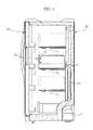
- the ice making unit 30, used in the refrigerator in accordance with an exemplary embodiment of the present invention is an independent kit, and the ice making unit 30 is separably installed in the freezing compartment 11 of the refrigerator. Specifically, the ice making unit 30 is put on a shelf in the freezing compartment 11, and thus, as shown in FIG. 1 , a vertical position of the ice making unit 30 can be freely changed if necessary.
- the ice making unit 30, as shown in FIGS. 2 and 3 includes an ice making case 300 defining an external appearance of the ice making unit 30, a plurality of ice making trays 310U and 310L disposed in the ice making case 300 to make ice therein, a water supply tank 320 disposed above the plurality of ice making trays 310U and 310L to receive water to be supplied into the plurality of ice making trays 310U and 310L, a guide tray 330 to distribute the water from the water supply tank 320 so as to guide the water into the plurality of ice making trays 310U and 310L, an ice separating device 340 to separate ice, made in the ice making trays 310U and 310L, from the ice making trays 310U and 310L, and an ice storage vessel 350 disposed below the ice making trays 310U and 310L to receive the ice separated from the plurality of ice making trays 310U and 310L.
- the ice making case 300 is installed at a front surface thereof with the ice separating device 340.
- the ice making case 300 includes a case body 301 in which the plurality of ice making trays 310U and 310L are arranged, a front cover 302 to cover a front surface of the case body 301, and a top cover 303 to define an upper surface of the case body 301.
- the case body 301 of the ice making case 300 is formed with a first opening 301 a to allow a user to observe ice making in the ice making trays 310U and 310L.
- the first opening 301 a is provided with a transparent window 304.
- the transparent window 304 is rotatably connected, at an upper end thereof, at the upper side of the first opening 301 a, to open or close the first opening 301 a via pivotal rotation thereof.
- the upper end of the transparent window 304 is rotatably coupled to one side of the top cover 303 that defines the upper surface of the ice making case 300. Accordingly, even in a state wherein the transparent window 304 closes the first opening 301a, it is possible to observe ice making in the plurality of ice making trays 310U and 310L from the outside through the transparent window 304.
- the front cover 302 of the ice making tray 300 is formed, at one side of an upper portion thereof, with a water supply tank installation hole 302a, to allow the water supply tank 320 to slide forward and rearward therethrough, thereby being pulled out and pushed into the ice making case 300, or being completely separated from the ice making case 300.
- the case body 301 is formed, at a lower portion of a front surface thereof, with a second opening 301b to allow the ice storage vessel 350 to slide forward and rearward therethrough, thereby being pulled out and pushed into the ice making case 300.
- the top cover 303 of the ice making case 300 is formed with a plurality of through-holes 303a, to introduce cold air in the freezing compartment 11 into the case body 301.
- a pair of ice making trays 310U and 310L is arranged up and down in parallel.
- one of the ice making trays 310U disposed above is referred to as an upper ice making tray 310U, and the other one disposed below is referred to as a lower ice making tray 310L.
- the pair of ice making trays 310U and 310L is rotatably installed up and down in parallel, and each is formed, at an upper surface thereof, with a plurality of ice making recesses 311 having an arched cross section.
- the guide tray 330 is installed at an upper portion of a rear surface of the case body 301 of the ice making case 300.
- the guide tray 330 is divided into two parts, namely, a first water supply guide portion 330a and a second water supply guide portion 330b, to distribute and guide the water discharged from the water supply tank 320 into the upper ice making tray 310U and the lower ice making tray 310L.
- the first water supply guide portion 330a of the guide tray 330 is located immediately above the upper ice making tray 310U, and the second water supply guide portion 330b is located beside and above the upper ice making tray 310U.
- the first water supply guide portion 330a is formed with a water supply hole 331 to supply the water from the first water supply guide portion 330a into the upper ice making tray 310U.
- the second water supply guide portion 330b is formed with a water supply tube 332 to supply the water from the second water supply guide portion 330b into the lower ice making tray 310L.
- the water supply tube 332 extends obliquely downward.
- a part of the water discharged from the water supply tank 320 into the guide tray 330 is delivered to the upper ice making tray 310U through the water supply hole 331 formed at the first water supply guide portion 330a, and the remaining water is delivered to the lower ice making tray 310L through the water supply tube 332 formed at the second water supply guide portion 330b.
- supply of water into the pair of ice making trays 310U and 310L can be accomplished in a very simple manner.
- the ice separating device 340 is a device to rotate the ice making trays 310U and 310L so as to separate the ice made in the ice making trays 310U and 310L.
- the ice separating device 340 simultaneously rotates the pair of ice making trays 310U and 310L, thereby simultaneously separating the ice from the pair of ice making trays 310U and 310L.
- the ice separating device 340 includes a lever 341 to be rotated about one end thereof upon receiving an external force, a driving gear 342 to be rotated by the lever 341, and a pair of driven gears 343 to be rotated upon receiving rotating force of the driving gear 342 so as to rotate the pair of ice making trays 310U and 310L, respectively.
- the driving gear 342 and the pair of driven gears 343 are installed at the front surface of the case body 301.
- a gear cover 306 is provided between the case body 301 and the front cover 302, to cover the driving gear 342 and the pair of driven gears 343.
- the gear cover 306 is centrally formed with a lever installation hole 306a, to allow one end of the lever 341 to be coupled to the driving gear 342.
- a lever guide slot 302b extends lengthwise vertically in one side of the front cover 302, to guide vertical movement of the lever 341.
- One end of the lever 341 is coupled to the center of the driving gear 342. Accordingly, as the lever 341 is rotated about one end thereof, the driving gear 342 is rotated together with the lever 341.
- the pair of driven gears 343 are arranged at upper and lower positions of the front surface of the ice making case 300 and are engaged with the driving gear 342. As the driven gears 343 are rotated according to rotation of the driving gear 342, they rotate the pair of ice making trays 310U and 310L, respectively.
- the driving gear 342 is elastically supported in a circumferential direction thereof by a torsion spring (not shown), such that it is rotated in a direction upon receiving an external force applied to the lever 341, and then, is returned to an original position thereof.
- the driving gear 342 is rotated in an opposite direction by an elastic restoration force of the torsion spring, causing the lever 341, the driven gears 343, and the pair of ice making trays 310U and 310L to be returned to their original positions as shown in FIG. 4 .
Abstract
An ice making unit (30) taking the form of a kit separably installed in a freezing compartment (11) of a refrigerator. The ice making unit (30) includes a water supply tank (320) to supply water, an ice making case (300) defining an external appearance of the ice making unit, the ice making case (300) being formed, at an upper portion of a front surface thereof, with a water supply tank installation hole to allow the water supply tank (320) to be slidably installed therethrough, at least one ice making tray (310L) installed in the ice making case (300) to receive the water supplied from the water supply tank (320), and an ice separating device (340) to separate ice from the ice making tray (310L), and the water supply tank is coupled to or separated from the ice making case (320) via forward and rearward sliding movement thereof. Supply of water into the ice making unit (30) can be accomplished via coupling or separation of the water supply tank.
Description
- The present invention relates to an ice making unit and a refrigerator having the same, and, more particularly, to an ice making unit separably installed in a freezing compartment and a refrigerator having the same.
- In general, a refrigerator is an apparatus incorporating a refrigeration cycle, to refrigerate or freeze articles stored therein using cold air generated from components of the refrigeration cycle. Some refrigerators have an ice making unit installed in a freezing compartment.
- Korean Patent Laid-Open Publication No.
10-2003-0060633 - In this case, a plurality of water receiving members is rotatably installed in the ice making tray. Also, a plurality of grips are installed at a front surface of the ice making tray, to rotate the plurality of water receiving members, so as to separate ice made in the respective water receiving members. When any one of the plurality of grips is rotated, the ice made in the corresponding water receiving member can be separated.
- However, the above-described conventional ice making unit and refrigerator having the same have a problem of inconvenient supply of water for use in ice making because the ice making tray must be separated from the ice maker body in order to fill water in the water receiving members of the ice making tray.
- Another problem of the above-described conventional ice making unit and refrigerator having the same is that it is necessary to fill water in the plurality of water receiving members one by one, and this further complicates supply of water for use in ice making.
- In addition, in the above-described conventional ice making unit and refrigerator having the same, every grip used to rotate each of the plurality of water receiving members must be rotated to separate ice made in the plurality of water receiving members, resulting in inconvenient separation of ice made in the water receiving members.
- In an aspect of the present invention, there is provided an ice making unit to achieve more easy supply of water for use in ice making, and a refrigerator having the same.
- In an aspect of the present invention, there is provided an ice making unit to achieve more easy supply of water into a plurality of ice making trays, and a refrigerator having the same.
- In an aspect of the present invention, there is provided an ice making tray to achieve more convenient separation of ice made in a plurality of ice making trays, and a refrigerator having the same.
- In accordance with an aspect of the invention, there is provided an ice making unit, which takes the form of a kit separably installed in a freezing compartment, wherein the ice making unit includes a water supply tank to supply water; an ice making case defining an external appearance of the ice making unit, the ice making case being formed, at an upper portion of a front surface thereof, with a water supply tank installation hole to allow the water supply tank to be slidably installed therethrough; at least one ice making tray installed in the ice making case to receive the water supplied from the water supply tank; and an ice separating device to separate ice from the at least one ice making tray, and the water supply tank is coupled to or separated from the ice making case via forward and rearward sliding movement thereof.
- The ice making case may be formed, at one side thereof, with a first opening to observe ice making in the at least one ice making tray, and the at least one ice making tray may include a plurality of ice making trays.
- A transparent window may be rotatably installed, at an upper end thereof, to an upper side of the first opening, to open or close the first opening.
- The at least one ice making tray may include an upper ice making tray and a lower ice making tray arranged up and down in parallel within the ice making case.
- A guide tray may be provided between the water supply tank and the upper ice making tray, to distribute and supply the water discharged from the water supply tank into the upper ice making tray and the lower ice making tray.
- The interior of the guide tray may be divided into two parts to distribute and supply the water into an upper ice making tray and a lower ice making tray, and may include a water supply hole to guide the water into the upper ice making tray and a water supply tube to guide the water into the lower ice making tray.
- The ice separating device may include a lever to be rotated about one end thereof upon receiving an external force, a driving gear to be rotated by the lever, and a pair of driven gears to be rotated by the driving gear so as to rotate the upper ice making tray and lower ice making tray, respectively.
- An ice storage vessel may be provided in a lower region of the ice making case, to receive the ice separated from the ice making tray, and the ice making case may be formed, at a lower portion of the front surface thereof, with a second opening, to allow the ice storage vessel to be slidably installed therethrough.
- In accordance with another aspect of the present invention, there is provided a refrigerator including a body having a freezing compartment, a door to open or close the freezing compartment, and an ice making unit taking the form of a kit separably installed to any one of the freezing compartment and the door, wherein the ice making unit includes a water supply tank to supply water; an ice making case defining an external appearance of the ice making unit, the ice making case being formed, at an upper portion of a front surface thereof, with a water supply tank installation hole to allow the water supply tank to be slidably installed therethrough; at least one ice making tray installed in the ice making case to receive the water supplied from the water supply tank; and an ice separating device to separate ice from the at least one ice making tray, and the water supply tank being coupled to or separated from the ice making case via forward and rearward sliding movement thereof.
- These and/or other aspects, features, and advantages of exemplary embodiments of the invention will become apparent and more readily appreciated from the following description of exemplary embodiments, taken in conjunction with the accompanying drawings, of which:
-
FIG. 1 is a side sectional view illustrating a refrigerator in accordance with an exemplary embodiment of the present invention; -
FIG. 2 is a perspective view illustrating an ice making unit of the refrigerator in accordance with an exemplary embodiment of the present invention; -
FIG. 3 is an exploded perspective view of the ice making unit of the refrigerator in accordance with an exemplary embodiment of the present invention; and -
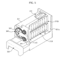
FIGS. 4 and5 are perspective views illustrating operation of the ice making unit of the refrigerator in accordance with an exemplary embodiment of the present invention. - Reference will now be made in detail to exemplary embodiments of the present invention, examples of which are illustrated in the accompanying drawings, wherein like reference numerals refer to like elements throughout. Exemplary embodiments are described below to explain the present invention by referring to the figures.
- Referring to
FIG. 1 illustrating a refrigerator in accordance with an exemplary embodiment of the present invention, the refrigerator includes abody 10 defining an external appearance of the refrigerator and having an open front surface, thebody 10 being formed therein with afreezing compartment 11 to freeze articles stored therein, and adoor 20 hingedly coupled at one side of thebody 10 to open or close thefreezing compartment 11. - A
compressor 12 to compress a refrigerant is installed in a rear lower region of thebody 10. Anevaporator 13 to generate cold air and a blowingfan 14 to generate suction and blowing force for circulation of the cold air generated from theevaporator 13 within thefreezing compartment 11 are installed at the rear side of thefreezing compartment 11. Thefreezing compartment 11 incorporates a plurality ofshelves 15 to divide the interior of thefreezing compartment 11 for efficient storage of various articles. Thedoor 20 is provided at an inner surface thereof with a plurality ofdoor shelves 21 to store beverage cans or containers, etc. - A refrigerator in accordance with an exemplary embodiment of the present invention includes an
ice making unit 30 installed in thefreezing compartment 11 to make ice. Theice making unit 30, used in the refrigerator in accordance with an exemplary embodiment of the present invention, is an independent kit, and theice making unit 30 is separably installed in thefreezing compartment 11 of the refrigerator. Specifically, theice making unit 30 is put on a shelf in thefreezing compartment 11, and thus, as shown inFIG. 1 , a vertical position of theice making unit 30 can be freely changed if necessary. - The
ice making unit 30, as shown inFIGS. 2 and3 , includes anice making case 300 defining an external appearance of theice making unit 30, a plurality ofice making trays ice making case 300 to make ice therein, awater supply tank 320 disposed above the plurality ofice making trays ice making trays guide tray 330 to distribute the water from thewater supply tank 320 so as to guide the water into the plurality ofice making trays device 340 to separate ice, made in theice making trays ice making trays ice storage vessel 350 disposed below theice making trays ice making trays water supply tank 320 to be separably installed to theice making case 300 of theice making unit 30, supply of water for use in ice making can be carried out by simply coupling thewater supply tank 320 into theice making case 30. - The
ice making case 300 is installed at a front surface thereof with theice separating device 340. The ice makingcase 300 includes acase body 301 in which the plurality ofice making trays front cover 302 to cover a front surface of thecase body 301, and atop cover 303 to define an upper surface of thecase body 301. Thecase body 301 of theice making case 300 is formed with afirst opening 301 a to allow a user to observe ice making in theice making trays first opening 301 a is provided with atransparent window 304. Thetransparent window 304 is rotatably connected, at an upper end thereof, at the upper side of thefirst opening 301 a, to open or close thefirst opening 301 a via pivotal rotation thereof. In the present exemplary embodiment, the upper end of thetransparent window 304 is rotatably coupled to one side of thetop cover 303 that defines the upper surface of theice making case 300. Accordingly, even in a state wherein thetransparent window 304 closes thefirst opening 301a, it is possible to observe ice making in the plurality ofice making trays transparent window 304. - The
front cover 302 of theice making tray 300 is formed, at one side of an upper portion thereof, with a water supplytank installation hole 302a, to allow thewater supply tank 320 to slide forward and rearward therethrough, thereby being pulled out and pushed into theice making case 300, or being completely separated from theice making case 300. Thecase body 301 is formed, at a lower portion of a front surface thereof, with a second opening 301b to allow theice storage vessel 350 to slide forward and rearward therethrough, thereby being pulled out and pushed into theice making case 300. - The
top cover 303 of theice making case 300 is formed with a plurality of through-holes 303a, to introduce cold air in thefreezing compartment 11 into thecase body 301. - In the present exemplary embodiment, a pair of
ice making trays ice making trays 310U disposed above is referred to as an upperice making tray 310U, and the other one disposed below is referred to as a lowerice making tray 310L. - The pair of
ice making trays ice making recesses 311 having an arched cross section. - The
guide tray 330 is installed at an upper portion of a rear surface of thecase body 301 of theice making case 300. Theguide tray 330 is divided into two parts, namely, a first watersupply guide portion 330a and a second watersupply guide portion 330b, to distribute and guide the water discharged from thewater supply tank 320 into the upperice making tray 310U and the lowerice making tray 310L. The first watersupply guide portion 330a of theguide tray 330 is located immediately above the upperice making tray 310U, and the second watersupply guide portion 330b is located beside and above the upperice making tray 310U. The first watersupply guide portion 330a is formed with awater supply hole 331 to supply the water from the first watersupply guide portion 330a into the upperice making tray 310U. The second watersupply guide portion 330b is formed with awater supply tube 332 to supply the water from the second watersupply guide portion 330b into the lowerice making tray 310L. For this, thewater supply tube 332 extends obliquely downward. - Accordingly, a part of the water discharged from the
water supply tank 320 into theguide tray 330 is delivered to the upperice making tray 310U through thewater supply hole 331 formed at the first watersupply guide portion 330a, and the remaining water is delivered to the lowerice making tray 310L through thewater supply tube 332 formed at the second watersupply guide portion 330b. As the water in thewater supply tank 320 is distributed into the pair ofice making trays guide tray 330, supply of water into the pair ofice making trays - The
ice separating device 340 is a device to rotate theice making trays ice making trays ice separating device 340 simultaneously rotates the pair ofice making trays ice making trays - The
ice separating device 340 includes alever 341 to be rotated about one end thereof upon receiving an external force, adriving gear 342 to be rotated by thelever 341, and a pair of drivengears 343 to be rotated upon receiving rotating force of thedriving gear 342 so as to rotate the pair ofice making trays driving gear 342 and the pair of drivengears 343 are installed at the front surface of thecase body 301. Agear cover 306 is provided between thecase body 301 and thefront cover 302, to cover thedriving gear 342 and the pair of driven gears 343. Thegear cover 306 is centrally formed with alever installation hole 306a, to allow one end of thelever 341 to be coupled to thedriving gear 342. Also, alever guide slot 302b extends lengthwise vertically in one side of thefront cover 302, to guide vertical movement of thelever 341. - One end of the
lever 341 is coupled to the center of thedriving gear 342. Accordingly, as thelever 341 is rotated about one end thereof, thedriving gear 342 is rotated together with thelever 341. The pair of drivengears 343 are arranged at upper and lower positions of the front surface of theice making case 300 and are engaged with thedriving gear 342. As the drivengears 343 are rotated according to rotation of thedriving gear 342, they rotate the pair ofice making trays driving gear 342 is elastically supported in a circumferential direction thereof by a torsion spring (not shown), such that it is rotated in a direction upon receiving an external force applied to thelever 341, and then, is returned to an original position thereof. - As shown in
FIG. 4 , if the user forces thelever 341 to rotate about one end thereof in a state wherein theice making recesses 311 face upward, thedriving gear 342 is rotated in a direction together with thelever 341, and simultaneously, the pair of drivengears 343 and the pair ofice making trays gears 343 are rotated as shown inFIG. 5 , causing the ice made in the pair ofice making trays single lever 341, all the ice made in the pair ofice making trays ice making unit 30. - After the manual external force applied to the
lever 341 is released, thedriving gear 342 is rotated in an opposite direction by an elastic restoration force of the torsion spring, causing thelever 341, the driven gears 343, and the pair ofice making trays FIG. 4 . - Although a few exemplary embodiments of the present invention have been shown and described, it would be appreciated by those skilled in the art that changes may be made in these exemplary embodiments without departing from the principles and spirit of the invention, the scope of which is defined in the claims and their equivalents.
Claims (15)
- An ice making unit, which takes the form of a kit separably installed in a freezing compartment, the ice making unit comprising:a water supply tank to supply water;an ice making case defining an external appearance of the ice making unit, the ice making case being formed, at an upper portion of a front surface thereof, with a water supply tank installation hole to allow the water supply tank to be slidably installed therethrough;at least one ice making tray installed in the ice making case to receive the water supplied from the water supply tank; andan ice separating device to separate ice from the at least one ice making tray,wherein the water supply tank is coupled to or separated from the ice making case via forward and rearward sliding movement thereof.
- The ice making unit according to claim 1, wherein the ice making case is formed, at one side thereof, with a first opening to observe ice making in the at least one ice making tray.
- The ice making unit according to claim 2, wherein a transparent window is rotatably installed, at an upper end thereof, to an upper side of the first opening, to open or close the first opening.
- The ice making unit according to claim 1, wherein the at least one ice making tray includes an upper ice making tray and a lower ice making tray arranged up and down in parallel within the ice making case.
- The ice making unit according to claim 4, further comprising a guide tray, which is provided between the water supply tank and the upper ice making tray, to distribute and supply the water discharged from the water supply tank into the upper ice making tray and the lower ice making tray.
- The ice making unit according to claim 5, wherein the interior of the guide tray is divided into two parts to distribute and supply the water into the upper ice making tray and the lower ice making tray, and includes a water supply hole to guide the water into the upper ice making tray and a water supply tube to guide the water into the lower ice making tray.
- The ice making unit according to claim 4, wherein the ice separating device includes a lever to be rotated about one end thereof upon receiving an external force, a driving gear to be rotated by the lever, and a pair of driven gears to be rotated by the driving gear so as to rotate the upper ice making tray and lower ice making tray, respectively.
- The ice making unit according to claim 1,
wherein an ice storage vessel is provided in a lower region of the ice making case, to receive the ice separated from the ice making tray, and
wherein the ice making case is formed, at a lower portion of the front surface thereof, with a second opening, to allow the ice storage vessel to be slidably installed therethrough. - A refrigerator comprising:a body having a freezing compartment;a door to open or close the freezing compartment; andan ice making unit taking the form of a kit separably installed to any one of the freezing compartment and the door,wherein the ice making unit comprises:a water supply tank to supply water;an ice making case defining an external appearance of the ice making unit, the ice making case being formed, at an upper portion of a front surface thereof, with a water supply tank installation hole to allow the water supply tank to be slidably installed therethrough;at least one ice making tray installed in the ice making case to receive the water supplied from the water supply tank; andan ice separating device to separate ice from the at least one ice making tray, andwherein the water supply tank is coupled to or separated from the ice making case via forward and rearward sliding movement thereof.
- The refrigerator according to claim 9, wherein the ice making case is formed, at one side thereof, with a first opening to observe ice making in the at least one ice making tray; and
wherein a transparent window is rotatably installed, at an upper end thereof, to an upper side of the first opening, to open or close the first opening. - The refrigerator according to claim 9, wherein the at least one ice making tray includes an upper ice making tray and a lower ice making tray arranged up and down in parallel within the ice making case.
- The refrigerator according to claim 11, further comprising a guide tray, which is provided between the water supply tank and the upper ice making tray, to distribute and supply the water discharged from the water supply tank into the upper ice making tray and the lower ice making tray.
- The refrigerator according to claim 12, wherein the interior of the guide tray is divided into two parts to distribute and supply the water into the upper ice making tray and the lower ice making tray, and includes a water supply hole to guide the water into the upper ice making tray and a water supply tube to guide the water into the lower ice making tray.
- The refrigerator according to claim 11, wherein the ice separating device includes a lever to be rotated about one end thereof upon receiving an external force, a driving gear to be rotated by the lever, and a pair of driven gears to be rotated by the driving gear so as to rotate the upper ice making tray and lower ice making tray, respectively.
- The refrigerator according to claim 9,
wherein an ice storage vessel is provided in a lower region of the ice making case, to receive the ice separated from the ice making tray, and
wherein the ice making case is formed, at a lower portion of the front surface thereof, with a second opening, to allow the ice storage vessel to be slidably installed therethrough.
Applications Claiming Priority (1)
| Application Number | Priority Date | Filing Date | Title |
|---|---|---|---|
| KR1020080004970A KR20090079043A (en) | 2008-01-16 | 2008-01-16 | Ice making unit and refrigerator having the same |
Publications (1)
| Publication Number | Publication Date |
|---|---|
| EP2080968A2 true EP2080968A2 (en) | 2009-07-22 |
Family
ID=40513408
Family Applications (1)
| Application Number | Title | Priority Date | Filing Date |
|---|---|---|---|
| EP08170900A Withdrawn EP2080968A2 (en) | 2008-01-16 | 2008-12-08 | Ice making unit and refrigerator having the same |
Country Status (4)
| Country | Link |
|---|---|
| US (1) | US20090178428A1 (en) |
| EP (1) | EP2080968A2 (en) |
| KR (1) | KR20090079043A (en) |
| CN (1) | CN101487651A (en) |
Cited By (6)
| Publication number | Priority date | Publication date | Assignee | Title |
|---|---|---|---|---|
| EP2363416A2 (en) | 2005-04-28 | 2011-09-07 | Mochida Pharmaceutical Co., Ltd. | Anti-platelet membrane glycoprotein VI monoclonal antibody |
| WO2011051142A3 (en) * | 2009-10-27 | 2011-09-29 | BSH Bosch und Siemens Hausgeräte GmbH | Ice maker |
| DE102017216530A1 (en) | 2017-09-19 | 2019-03-21 | BSH Hausgeräte GmbH | Eisbereitervorrichtung |
| DE102017216531A1 (en) | 2017-09-19 | 2019-03-21 | BSH Hausgeräte GmbH | Eisbereitervorrichtung |
| DE102017216529A1 (en) | 2017-09-19 | 2019-03-21 | BSH Hausgeräte GmbH | Eisbereitervorrichtung |
| CN111486627A (en) * | 2019-01-28 | 2020-08-04 | 日本电产三协株式会社 | Ice making device |
Families Citing this family (19)
| Publication number | Priority date | Publication date | Assignee | Title |
|---|---|---|---|---|
| JP5478365B2 (en) * | 2010-05-28 | 2014-04-23 | 三菱電機株式会社 | refrigerator |
| CN102455095A (en) * | 2010-10-29 | 2012-05-16 | 泰州乐金电子冷机有限公司 | Ice separating mechanism for ice making equipment |
| CN102425896B (en) * | 2011-12-16 | 2013-11-27 | 合肥荣事达三洋电器股份有限公司 | Manually operated ice machine |
| CN102419042A (en) * | 2011-12-27 | 2012-04-18 | 苏州新中达汽车饰件有限公司 | Ice making box |
| WO2013127072A1 (en) * | 2012-02-29 | 2013-09-06 | 海信容声(广东)冰箱有限公司 | Independent-type ice making device |
| US9310116B2 (en) * | 2012-11-16 | 2016-04-12 | Whirlpool Corporation | Ice storage to hold ice and minimize melting of ice spheres |
| US9500398B2 (en) | 2012-12-13 | 2016-11-22 | Whirlpool Corporation | Twist harvest ice geometry |
| US9759472B2 (en) | 2012-12-13 | 2017-09-12 | Whirlpool Corporation | Clear ice maker with warm air flow |
| US9470448B2 (en) | 2012-12-13 | 2016-10-18 | Whirlpool Corporation | Apparatus to warm plastic side of mold |
| US9557087B2 (en) | 2012-12-13 | 2017-01-31 | Whirlpool Corporation | Clear ice making apparatus having an oscillation frequency and angle |
| US9915458B2 (en) | 2014-10-23 | 2018-03-13 | Whirlpool Corporation | Method and apparatus for increasing rate of ice production in an automatic ice maker |
| US20180283759A1 (en) * | 2015-04-17 | 2018-10-04 | David Bess | Ice Tray Assembly |
| CN106560667B (en) * | 2015-10-06 | 2019-08-16 | 日立空调·家用电器株式会社 | Refrigerator |
| JP6556012B2 (en) * | 2015-10-06 | 2019-08-07 | 日立グローバルライフソリューションズ株式会社 | refrigerator |
| US10739053B2 (en) | 2017-11-13 | 2020-08-11 | Whirlpool Corporation | Ice-making appliance |
| US10907874B2 (en) | 2018-10-22 | 2021-02-02 | Whirlpool Corporation | Ice maker downspout |
| EP3653975B1 (en) * | 2018-11-16 | 2023-09-20 | LG Electronics Inc. | Home appliance with an ice maker |
| CN114838546B (en) | 2018-11-16 | 2023-12-29 | Lg电子株式会社 | Ice maker and refrigerator |
| WO2023139653A1 (en) * | 2022-01-18 | 2023-07-27 | 三菱電機株式会社 | Refrigerator |
Family Cites Families (3)
| Publication number | Priority date | Publication date | Assignee | Title |
|---|---|---|---|---|
| BR0303842B1 (en) * | 2003-09-16 | 2013-12-17 | ICE FORM SUPPLY SYSTEM IN COOLING DEVICES | |
| KR100705182B1 (en) * | 2006-05-29 | 2007-04-09 | 엘지전자 주식회사 | Ice tray assembly used in a refrigerator |
| KR100714559B1 (en) * | 2006-06-28 | 2007-05-07 | 엘지전자 주식회사 | Ice tray assembly used in a refrigerator |
-
2008
- 2008-01-16 KR KR1020080004970A patent/KR20090079043A/en not_active Application Discontinuation
- 2008-08-14 US US12/222,727 patent/US20090178428A1/en not_active Abandoned
- 2008-08-28 CN CNA2008102144897A patent/CN101487651A/en active Pending
- 2008-12-08 EP EP08170900A patent/EP2080968A2/en not_active Withdrawn
Cited By (7)
| Publication number | Priority date | Publication date | Assignee | Title |
|---|---|---|---|---|
| EP2363416A2 (en) | 2005-04-28 | 2011-09-07 | Mochida Pharmaceutical Co., Ltd. | Anti-platelet membrane glycoprotein VI monoclonal antibody |
| WO2011051142A3 (en) * | 2009-10-27 | 2011-09-29 | BSH Bosch und Siemens Hausgeräte GmbH | Ice maker |
| DE102017216530A1 (en) | 2017-09-19 | 2019-03-21 | BSH Hausgeräte GmbH | Eisbereitervorrichtung |
| DE102017216531A1 (en) | 2017-09-19 | 2019-03-21 | BSH Hausgeräte GmbH | Eisbereitervorrichtung |
| DE102017216529A1 (en) | 2017-09-19 | 2019-03-21 | BSH Hausgeräte GmbH | Eisbereitervorrichtung |
| CN111486627A (en) * | 2019-01-28 | 2020-08-04 | 日本电产三协株式会社 | Ice making device |
| US11359849B2 (en) | 2019-01-28 | 2022-06-14 | Nidec Sankyo Corporation | Ice making device |
Also Published As
| Publication number | Publication date |
|---|---|
| KR20090079043A (en) | 2009-07-21 |
| US20090178428A1 (en) | 2009-07-16 |
| CN101487651A (en) | 2009-07-22 |
Similar Documents
| Publication | Publication Date | Title |
|---|---|---|
| EP2080968A2 (en) | Ice making unit and refrigerator having the same | |
| US8161767B2 (en) | Ice making apparatus of refrigerator | |
| US8443619B2 (en) | Ice making unit and refrigerator having the same | |
| US8459057B2 (en) | Refrigerator with ice supply device | |
| US8443620B2 (en) | Ice tray assembly and refrigerator having same | |
| US8016160B2 (en) | Refrigerator related technology | |
| US9927163B2 (en) | Domestic refrigerator including an ice dispenser | |
| KR20100122230A (en) | Refrigerator | |
| EP2933590B1 (en) | Refrigerator | |
| US20060162369A1 (en) | Refrigerator | |
| KR102615047B1 (en) | Refrigerator | |
| KR20110138777A (en) | Refrigerator | |
| WO2009057891A2 (en) | Ice maker and refrigerator | |
| KR20100022654A (en) | Dispenser of refrigerator and refrigerator having the same | |
| JPH10153382A (en) | Shelf device for refrigerator | |
| KR102451448B1 (en) | Ice maker and refrigerator having the same | |
| KR101258437B1 (en) | Ice making unit and refrigerator having the same | |
| CN102893105B (en) | Comprise the refrigerating appliance of ice machine | |
| KR101260522B1 (en) | Ice-making means for refrigerator | |
| CN112393483A (en) | Ice maker for refrigerator and refrigerator | |
| US20080174219A1 (en) | Refrigerator, door for refrigerator, and dispensing apparatus for refrigerator | |
| KR101346488B1 (en) | Refrigerator | |
| KR101446495B1 (en) | Refrigerator | |
| KR20070093611A (en) | Dispensor in refrigerator | |
| KR200309998Y1 (en) | Twist ice-machine for refrigerator |
Legal Events
| Date | Code | Title | Description |
|---|---|---|---|
| PUAI | Public reference made under article 153(3) epc to a published international application that has entered the european phase |
Free format text: ORIGINAL CODE: 0009012 |
|
| AK | Designated contracting states |
Kind code of ref document: A2 Designated state(s): AT BE BG CH CY CZ DE DK EE ES FI FR GB GR HR HU IE IS IT LI LT LU LV MC MT NL NO PL PT RO SE SI SK TR |
|
| AX | Request for extension of the european patent |
Extension state: AL BA MK RS |
|
| STAA | Information on the status of an ep patent application or granted ep patent |
Free format text: STATUS: THE APPLICATION IS DEEMED TO BE WITHDRAWN |
|
| 18D | Application deemed to be withdrawn |
Effective date: 20110701 |