EP2080965B1 - Device for attaching a solar collector - Google Patents
Device for attaching a solar collector Download PDFInfo
- Publication number
- EP2080965B1 EP2080965B1 EP09100037.2A EP09100037A EP2080965B1 EP 2080965 B1 EP2080965 B1 EP 2080965B1 EP 09100037 A EP09100037 A EP 09100037A EP 2080965 B1 EP2080965 B1 EP 2080965B1
- Authority
- EP
- European Patent Office
- Prior art keywords
- solar collector
- clamping
- roof hook
- mounting
- roof
- Prior art date
- Legal status (The legal status is an assumption and is not a legal conclusion. Google has not performed a legal analysis and makes no representation as to the accuracy of the status listed.)
- Active
Links
- 101100498160 Mus musculus Dach1 gene Proteins 0.000 description 3
- 239000011449 brick Substances 0.000 description 1
- 230000001419 dependent effect Effects 0.000 description 1
- 238000003780 insertion Methods 0.000 description 1
- 230000037431 insertion Effects 0.000 description 1
- 238000009434 installation Methods 0.000 description 1
- 239000000725 suspension Substances 0.000 description 1
Images


Classifications
-
- F—MECHANICAL ENGINEERING; LIGHTING; HEATING; WEAPONS; BLASTING
- F24—HEATING; RANGES; VENTILATING
- F24S—SOLAR HEAT COLLECTORS; SOLAR HEAT SYSTEMS
- F24S25/00—Arrangement of stationary mountings or supports for solar heat collector modules
- F24S25/60—Fixation means, e.g. fasteners, specially adapted for supporting solar heat collector modules
- F24S25/63—Fixation means, e.g. fasteners, specially adapted for supporting solar heat collector modules for fixing modules or their peripheral frames to supporting elements
- F24S25/634—Clamps; Clips
-
- F—MECHANICAL ENGINEERING; LIGHTING; HEATING; WEAPONS; BLASTING
- F24—HEATING; RANGES; VENTILATING
- F24S—SOLAR HEAT COLLECTORS; SOLAR HEAT SYSTEMS
- F24S25/00—Arrangement of stationary mountings or supports for solar heat collector modules
- F24S25/30—Arrangement of stationary mountings or supports for solar heat collector modules using elongate rigid mounting elements extending substantially along the supporting surface, e.g. for covering buildings with solar heat collectors
-
- F—MECHANICAL ENGINEERING; LIGHTING; HEATING; WEAPONS; BLASTING
- F24—HEATING; RANGES; VENTILATING
- F24S—SOLAR HEAT COLLECTORS; SOLAR HEAT SYSTEMS
- F24S25/00—Arrangement of stationary mountings or supports for solar heat collector modules
- F24S25/60—Fixation means, e.g. fasteners, specially adapted for supporting solar heat collector modules
- F24S25/61—Fixation means, e.g. fasteners, specially adapted for supporting solar heat collector modules for fixing to the ground or to building structures
- F24S25/613—Fixation means, e.g. fasteners, specially adapted for supporting solar heat collector modules for fixing to the ground or to building structures in the form of bent strips or assemblies of strips; Hook-like connectors; Connectors to be mounted between building-covering elements
-
- F—MECHANICAL ENGINEERING; LIGHTING; HEATING; WEAPONS; BLASTING
- F24—HEATING; RANGES; VENTILATING
- F24S—SOLAR HEAT COLLECTORS; SOLAR HEAT SYSTEMS
- F24S25/00—Arrangement of stationary mountings or supports for solar heat collector modules
- F24S25/60—Fixation means, e.g. fasteners, specially adapted for supporting solar heat collector modules
- F24S25/63—Fixation means, e.g. fasteners, specially adapted for supporting solar heat collector modules for fixing modules or their peripheral frames to supporting elements
- F24S25/632—Side connectors; Base connectors
-
- F—MECHANICAL ENGINEERING; LIGHTING; HEATING; WEAPONS; BLASTING
- F24—HEATING; RANGES; VENTILATING
- F24S—SOLAR HEAT COLLECTORS; SOLAR HEAT SYSTEMS
- F24S25/00—Arrangement of stationary mountings or supports for solar heat collector modules
- F24S2025/01—Special support components; Methods of use
- F24S2025/016—Filling or spacing means; Elastic means
-
- F—MECHANICAL ENGINEERING; LIGHTING; HEATING; WEAPONS; BLASTING
- F24—HEATING; RANGES; VENTILATING
- F24S—SOLAR HEAT COLLECTORS; SOLAR HEAT SYSTEMS
- F24S25/00—Arrangement of stationary mountings or supports for solar heat collector modules
- F24S25/60—Fixation means, e.g. fasteners, specially adapted for supporting solar heat collector modules
- F24S2025/6008—Fixation means, e.g. fasteners, specially adapted for supporting solar heat collector modules by using toothed elements
-
- Y—GENERAL TAGGING OF NEW TECHNOLOGICAL DEVELOPMENTS; GENERAL TAGGING OF CROSS-SECTIONAL TECHNOLOGIES SPANNING OVER SEVERAL SECTIONS OF THE IPC; TECHNICAL SUBJECTS COVERED BY FORMER USPC CROSS-REFERENCE ART COLLECTIONS [XRACs] AND DIGESTS
- Y02—TECHNOLOGIES OR APPLICATIONS FOR MITIGATION OR ADAPTATION AGAINST CLIMATE CHANGE
- Y02B—CLIMATE CHANGE MITIGATION TECHNOLOGIES RELATED TO BUILDINGS, e.g. HOUSING, HOUSE APPLIANCES OR RELATED END-USER APPLICATIONS
- Y02B10/00—Integration of renewable energy sources in buildings
- Y02B10/20—Solar thermal
-
- Y—GENERAL TAGGING OF NEW TECHNOLOGICAL DEVELOPMENTS; GENERAL TAGGING OF CROSS-SECTIONAL TECHNOLOGIES SPANNING OVER SEVERAL SECTIONS OF THE IPC; TECHNICAL SUBJECTS COVERED BY FORMER USPC CROSS-REFERENCE ART COLLECTIONS [XRACs] AND DIGESTS
- Y02—TECHNOLOGIES OR APPLICATIONS FOR MITIGATION OR ADAPTATION AGAINST CLIMATE CHANGE
- Y02E—REDUCTION OF GREENHOUSE GAS [GHG] EMISSIONS, RELATED TO ENERGY GENERATION, TRANSMISSION OR DISTRIBUTION
- Y02E10/00—Energy generation through renewable energy sources
- Y02E10/40—Solar thermal energy, e.g. solar towers
- Y02E10/47—Mountings or tracking
Definitions
- the invention relates to a device for fastening a solar collector on at least one roof hook.
- Solar collectors are usually mounted on a roof via a support structure (e.g., a roof hook or a mounting rail).
- the collector attachment is complex in conventional mounting systems, time-consuming and often not tool-free. An adjustability of the collector is ensured with a high number of parts.
- roof structures can prevent lateral insertion of the collector on the corresponding support system and complicate the assembly.
- DE 101 32 557 A1 shows a mounting profile for mounting photovoltaic modules.
- a mounting profile is attached to a roof structure by means of a rafter anchor. In the mounting profile then a hook is latched. A photovoltaic module is inserted into this suspension hook and then bolted to the mounting profile.
- Object of the present invention is to allow installation of a solar collector on a roof hook without tools such as wrenches or the like.
- Claim 1 protects a fastening device for the attachment of a solar collector, comprising at least one roof hook.
- the roof hook has a toothing on one side, with clamping pieces, which are slidably mounted on the at least one roof hook, the attached clamping pieces on the side facing away from the teeth of the roof hook side each have a clamping lever and the clamping pieces on the side of the toothing on have at least one elastic retaining piece.
- the fastening device comprises at least one mounting rail for mounting the solar collector on the roof hook, which has a toothing, which engages positively in the toothing of the at least one roof hook, wherein by means of the clamping lever of the solar collector via the resilient holding pieces frictionally with the at least one roof hook connectable or detachable.
- Claim 2 protects a solar collector and a fastening device, in which instead of the mounting rail of the solar collector itself has the teeth, which engages positively in the toothing of the at least one roof hook.
- the assembly time is reduced and increases safety during assembly. A tool is no longer necessary for the attachment of the solar collector.
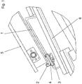
- FIG. 1 shows a solar collector 5, which is fixed by means of a roof hook 1, at least one mounting rail 4 and at least one clamping piece 2 with a clamping lever 3 on a roof (brick) 6. How many clamping pieces are used to fix the collector depends on the local conditions and the collector design. Preferably, four clamping pieces are needed.
- the solar collector 5 can in a further embodiment in the Figures 5 and 6 be fixed without the mounting rail 4 on the roof 6.
- the roof hook 1 has a toothing 7 on one side and clamping pieces 2, which are mounted on the roof hook 1 slidably.
- the toothing 7 can in principle also be located on both sides of the roof hook 1. Further, the clamping pieces 2 on the side facing away from the toothing 7 each have a clamping lever. 3
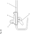
- FIGS. 3a to 3f show the operation of the fastening device according to the invention.
- the clamping pieces 2 on the side of the toothing 7 have at least one resilient holding piece 8.
- the solar collector 5 or the at least one mounting rail 4 for fixing the solar collector 5 also have a toothing 9 which engages positively in the toothing 7 of the roof hook 1.
- the clamping lever 3 of the clamping pieces 2 and the spring-elastic holding pieces 8 By means of the clamping lever 3 of the clamping pieces 2 and the spring-elastic holding pieces 8, the solar collector 5 or the mounting rail 4 for attaching the solar collector 5 frictionally connected to the roof hooks 1 or detachable. This is done after the clamping pieces 2 are inserted and prepositioned on the roof hook 1 such that the clamping pieces 2, the horizontal position, as in the FIGS. 3a to 3f shown on the roof hook 1 have taken.
- the mounting rail 4 then slides along the resilient holding piece 8 of the clamping piece 2, is then fixed by the intermeshing of the teeth 7 and 9 positively and secured with the clamping lever 3 of the clamping piece 2 non-positively. With the tensioning of the lever 3, a positive connection between the mounting rail 4, the clamping pieces 2 and the roof hook 1 is ensured.
- the resilient retaining piece 8 is shaped so that the receptacle and the fixation of the mounting rail 4 is favored during and after assembly in which, for example, the holding piece 8 is hook-shaped.
- the mounting rail 4 ends on a side facing away from the toothing 9 with a side member 10. This element 10 is the hook-shaped retaining piece 8 geometrically adapted so that it slides into the retaining piece 8 during assembly and the mounting rail 4 secures against slipping out.
- FIG. 4 The solar collector 5 is placed on the mounting rail 4, then inserted after loosening the clamping pieces 2 by the clamping lever 3 under the clamping pieces 2 and finally tightened and secured by means of the clamping lever 3.
- a further preferred embodiment of the invention is in the Figures 5 and 6 shown.
- the attachment of the solar collector 5 takes place in each case at its lower or upper end on the roof 6 directly by means of the roof hook 1, the clamping pieces 2 and the clamping lever 3.
- a mounting rail 4 is not required.
- the mounting rail or the solar collector can be fastened in a simple, fast and safe way without tools.
Description
Die Erfindung bezieht sich auf eine Vorrichtung zur Befestigung eines Solarkollektors auf mindestens einem Dachhaken.The invention relates to a device for fastening a solar collector on at least one roof hook.
Solarkollektoren werden meistens auf einem Dach über eine Trägerkonstruktion (z.B. ein Dachhaken oder eine Montageschiene) befestigt. Die Kollektorbefestigung ist bei herkömmlichen Montagesystemen aufwendig, zeitintensiv und oft nicht werkzeugfrei. Auch eine Verstellbarkeit des Kollektors wird mit einer hohen Anzahl von Teilen gewährleistet. Ferner können Dachaufbauten ein seitliches Einschieben des Kollektors auf das entsprechende Trägersystem verhindern und die Montage erschweren.Solar collectors are usually mounted on a roof via a support structure (e.g., a roof hook or a mounting rail). The collector attachment is complex in conventional mounting systems, time-consuming and often not tool-free. An adjustability of the collector is ensured with a high number of parts. Furthermore, roof structures can prevent lateral insertion of the collector on the corresponding support system and complicate the assembly.
Aufgabe der vorliegenden Erfindung ist es, eine Montage eines Solarkollektors auf einem Dachhaken auch ohne Werkzeug wie Schraubenschlüssel oder ähnliches zu ermöglichen.Object of the present invention is to allow installation of a solar collector on a roof hook without tools such as wrenches or the like.
Dies wird gemäß den Merkmalen der unabhängigen Vorrichtungsansprüche 1 und 2 erreicht. Anspruch 1 schützt eine Befestigungsvorrichtung für die Befestigung eines Solarkollektors, umfassend mindestens einen Dachhaken. Der Dachhaken verfügt dabei über eine Verzahnung auf einer Seite, mit Spannstücken, welche auf dem mindestens einen Dachhaken verschiebbar angebracht sind, wobei die angebrachten Spannstücke auf der der Verzahnung des Dachhakens abgewandten Seite jeweils über einen Spannhebel verfügen und die Spannstücke auf der Seite der Verzahnung über mindestens ein federelastisches Haltestück verfügen. Gemäß Anspruch 1 umfasst die Befestigungsvorrichtung mindestens eine Montageschiene zur Befestigung des Solarkollektors auf dem Dachhaken, die über eine Verzahnung verfügt, die in die Verzahnung des mindestens einen Dachhakens formschlüssig eingreift, wobei mittels des Spannhebels der Solarkollektor über die federelastischen Haltestücke kraftschlüssig mit dem mindestens einen Dachhaken verbindbar oder lösbar ist.This is achieved according to the features of the
Anspruch 2 schützt einen Solarkollektor und eine Befestigungsvorrichtung, bei dem anstelle der Montageschiene der Solarkollektor selbst über die Verzahnung verfügt, welche in die Verzahnung des mindestens einen Dachhakens formschlüssig eingreift.Claim 2 protects a solar collector and a fastening device, in which instead of the mounting rail of the solar collector itself has the teeth, which engages positively in the toothing of the at least one roof hook.
Mit der erfindungsgemäßen Befestigungsvorrichtung wird die Montagezeit reduziert und die Sicherheit bei der Montage erhöht. Ein Werkzeug ist für die Befestigung des Solarkollektors nicht mehr notwendig.With the fastening device according to the invention, the assembly time is reduced and increases safety during assembly. A tool is no longer necessary for the attachment of the solar collector.
Vorteilhafte Ausgestaltungen ergeben sich durch die Merkmale der abhängigen Ansprüche. Die Erfindung wird nun anhand der folgenden Figuren detailliert erläutert. Hierbei zeigen
-
Fig. 1 einen Solarkollektor, der am Dach mittels des Dachhakens der erfindungsgemäßen Befestigungsvorrichtung befestigt ist -
Fig. 2 der Dachhaken der erfindungsgemäßen Befestigungsvorrichtung, mit einem Spannstück -
Fig. 3a bis 3f die einzelne Schritte der Befestigung des Solarkollektors -
Fig. 4 Ansicht des Dachhakens mit der Montageschiene von oben -
Fig. 5 Befestigung des erfindungsgemäßen Solarkollektors an seinem unteren Ende am Dach mittels des Dachhakens -
Fig. 6 Befestigung des erfindungsgemäßen Solarkollektors an seinem oberen Ende am Dach mittels des Dachhakens.
-
Fig. 1 a solar collector which is fixed to the roof by means of the roof hook of the fastening device according to the invention -
Fig. 2 the roof hook of the fastening device according to the invention, with a clamping piece -
Fig. 3a to 3f the single steps of fixing the solar collector -
Fig. 4 View of the roof hook with the mounting rail from above -
Fig. 5 Attachment of the solar collector according to the invention at its lower end to the roof by means of the roof hook -
Fig. 6 Attachment of the solar collector according to the invention at its upper end on the roof by means of the roof hook.
Wie aus
Eine weitere bevorzugte Ausführungsform der Erfindung ist in den
Durch die geometrisch abgestimmte Ausbildung der Montageschiene 4 bzw. des Solarkollektors 5 und der Spannstücke 2 lässt sich die Montageschiene bzw. der Solarkollektor auf einfache, schnelle und sichere Weise ohne Werkzeug befestigen.Due to the geometrically coordinated design of the
Claims (6)
- Mounting device for mounting a solar collector (5), comprising at least one roof hook (1) which has teeth (7) on one side, wherein the mounting device comprises at least one mounting rail (4) for mounting the solar collector (5) on the roof hook (1), the mounting rail having teeth (9) which engage in the teeth (7) of the at least one roof hook (1) in a form-fitting manner, characterised in that the mounting device comprises at least one clamping element (2) movably mounted on the at least one roof hook (1), wherein the at least one mounted clamping element (2) comprises a clamping lever (3) on the side facing away from the teeth (7) of the roof hook (1), wherein the at least one clamping element (2) comprises at least one spring elastic retaining element (8) on the side of the teeth (7), wherein the at least one mounting rail (4) for mounting the solar collector (5) is connected to or detached from the at least one roof hook (1) via the spring elastic retaining elements (8) by means of the clamping lever (3) in a force-fitting manner.
- Solar collector and mounting device for mounting the solar collector (5), wherein the mounting device comprises at least one roof hook (1) which has teeth (7) on one side, characterised in that the mounting device comprises at least one clamping element (2) movably mounted on the at least one roof hook (1), wherein the at least one mounted clamping element (2) comprises a clamping lever (3) on the side facing away from the teeth (7) of the roof hook (1), wherein the at least one clamping element (2) comprises at least one spring elastic retaining element (8) on the side of the teeth (7), wherein the solar collector (5) comprises teeth (9) which engage in the teeth (7) of the at least one roof hook (1) in a form-fitting manner, wherein the solar collector (5) is connected to or detached from the at least one roof hook (1) via the spring elastic retaining elements (8) by means of the clamping lever (3) in a force-fitting manner.
- Mounting device according to claim 1, characterised in that the two ends of the spring elastic retaining elements (8) of the clamping elements (2) are configured so that a side element (10) of the at least one mounting rail (4) is secured therein.
- Solar collector and mounting device according to claim 2, characterised in that the two ends of the spring elastic retaining elements (8) of the clamping elements (2) are configured so that a side element (10) of the solar collector (5) is secured therein.
- Mounting device according to claim 3, characterised in that the spring elastic retaining elements (8) of the clamping elements (2) are hook-shaped.
- Solar collector and mounting device according to claim 4, characterised in that the spring elastic retaining elements (8) of the clamping elements (2) are hook-shaped.
Priority Applications (1)
| Application Number | Priority Date | Filing Date | Title |
|---|---|---|---|
| PL09100037T PL2080965T3 (en) | 2008-01-21 | 2009-01-14 | Device for attaching a solar collector |
Applications Claiming Priority (1)
| Application Number | Priority Date | Filing Date | Title |
|---|---|---|---|
| AT0007808A AT506323B1 (en) | 2008-01-21 | 2008-01-21 | DEVICE FOR FIXING A SOLAR COLLECTOR |
Publications (3)
| Publication Number | Publication Date |
|---|---|
| EP2080965A2 EP2080965A2 (en) | 2009-07-22 |
| EP2080965A3 EP2080965A3 (en) | 2011-04-27 |
| EP2080965B1 true EP2080965B1 (en) | 2017-09-20 |
Family
ID=40545871
Family Applications (1)
| Application Number | Title | Priority Date | Filing Date |
|---|---|---|---|
| EP09100037.2A Active EP2080965B1 (en) | 2008-01-21 | 2009-01-14 | Device for attaching a solar collector |
Country Status (6)
| Country | Link |
|---|---|
| EP (1) | EP2080965B1 (en) |
| AT (1) | AT506323B1 (en) |
| DE (1) | DE102009004904A1 (en) |
| ES (1) | ES2644761T3 (en) |
| HU (1) | HUE034735T2 (en) |
| PL (1) | PL2080965T3 (en) |
Families Citing this family (9)
| Publication number | Priority date | Publication date | Assignee | Title |
|---|---|---|---|---|
| FR2958024B1 (en) * | 2010-03-25 | 2014-06-13 | Hoggar Solution | DEVICE FOR FIXING SOLAR PANELS ON A STRUCTURE |
| DE102011084213A1 (en) * | 2011-06-07 | 2012-12-13 | Mounting Systems Gmbh | Frame arrangement, profile rail and solar module arrangement |
| WO2013037384A1 (en) * | 2011-09-15 | 2013-03-21 | Renusol Gmbh | Device for fastening a mounting rail on a roof hook |
| DE202012004333U1 (en) * | 2012-02-13 | 2013-02-01 | Werner Ilzhöfer | Device for supporting at least one solar module |
| EP2674692A1 (en) * | 2012-06-12 | 2013-12-18 | voestalpine Polynorm BV | Holder for a solar collector or a solar module |
| US10505492B2 (en) | 2016-02-12 | 2019-12-10 | Solarcity Corporation | Building integrated photovoltaic roofing assemblies and associated systems and methods |
| PL3740725T3 (en) | 2018-01-17 | 2023-01-30 | Panelclaw, Inc. | Attachment mechanism for a framed solar module |
| DE102018122176A1 (en) * | 2018-09-11 | 2020-03-12 | Sl Rack Gmbh | Roof hook |
| NL2022505B1 (en) * | 2019-02-04 | 2020-08-19 | Esdec B V | Solar panel support bracket and method for supporting a solar panel |
Family Cites Families (7)
| Publication number | Priority date | Publication date | Assignee | Title |
|---|---|---|---|---|
| DE2335223A1 (en) * | 1973-07-11 | 1975-01-30 | Bautek | Edge fastener for flat roof covering felt - has locking and covering profiles and height adjusting members |
| DE19727302C1 (en) * | 1997-06-27 | 1998-08-20 | Thyssen Industrie | Bearing structure of longitudinal and transverse supports |
| DE10132557C2 (en) * | 2000-11-20 | 2003-04-10 | Antec Solar Gmbh | Mounting profile for mounting photovoltaic modules and mounting system |
| DE102004012412A1 (en) * | 2004-03-13 | 2005-09-29 | Stiebel Eltron Gmbh & Co. Kg | Solar panel securing device e.g. for securing to roof, has solar heat collectors resting on supporting bar and connected with catches being on the roof supports and roof slats connected are relocatable with supporting bar |
| NL1028379C2 (en) * | 2005-02-23 | 2006-08-24 | Girasol Internat B V | Device and method for fixing objects, in particular solar panels, on a roof. |
| DE202005004348U1 (en) * | 2005-03-17 | 2005-07-28 | Kaack, Peter | Aluminium bracket for roof mounting solar panels has an angled strip secured to the roof and taking a support bracket with a clip fitting |
| DE102005058065A1 (en) * | 2005-05-04 | 2006-11-30 | Citak, Fatma | Aluminum roof hook for fastening e.g. solar module on roof, has base plate and clamp that are connected by double lock function, where clamp, base plate and angle anchor plate are connected with each other using screws and nuts |
-
2008
- 2008-01-21 AT AT0007808A patent/AT506323B1/en not_active IP Right Cessation
-
2009
- 2009-01-14 PL PL09100037T patent/PL2080965T3/en unknown
- 2009-01-14 ES ES09100037.2T patent/ES2644761T3/en active Active
- 2009-01-14 EP EP09100037.2A patent/EP2080965B1/en active Active
- 2009-01-14 HU HUE09100037A patent/HUE034735T2/en unknown
- 2009-01-16 DE DE102009004904A patent/DE102009004904A1/en not_active Withdrawn
Non-Patent Citations (1)
| Title |
|---|
| None * |
Also Published As
| Publication number | Publication date |
|---|---|
| EP2080965A3 (en) | 2011-04-27 |
| EP2080965A2 (en) | 2009-07-22 |
| ES2644761T3 (en) | 2017-11-30 |
| PL2080965T3 (en) | 2018-01-31 |
| AT506323A4 (en) | 2009-08-15 |
| DE102009004904A1 (en) | 2009-07-23 |
| HUE034735T2 (en) | 2018-02-28 |
| AT506323B1 (en) | 2009-08-15 |
Similar Documents
| Publication | Publication Date | Title |
|---|---|---|
| EP2080965B1 (en) | Device for attaching a solar collector | |
| DE102010018916B4 (en) | Device for fastening a mounting rail to a roof hook | |
| EP2435768B1 (en) | Apparatus for fastening a mounting rail to a threaded shaft | |
| DE102011052129B4 (en) | Fastening system for fastening solar modules | |
| WO2012113491A1 (en) | Fixing system for cables, in particular in wind turbines | |
| EP2391855A2 (en) | Solar module attachment | |
| DE202008000997U1 (en) | fastening system | |
| EP2549563B1 (en) | System comprising a battery tray and a tray receiver for mounting the battey tray in a battery cabinet of a wind turbine | |
| DE102010005194A1 (en) | Connecting device for components | |
| EP2841789A1 (en) | Means for mounting a contact line of a device for monitoring brake lining wear | |
| DE102009005236B4 (en) | Rail vehicle with a system housing attached by means of a console | |
| WO2014020006A1 (en) | Fastening element for mounting solar modules or solar collectors on a roof, and pitched roof having a fastening element | |
| DE202010007681U1 (en) | roof hook | |
| DE10236550B4 (en) | Holding device for a cable harness shoe element | |
| DE102013010006B3 (en) | Fastening arrangement for an exterior mirror of a vehicle | |
| EP3043123A1 (en) | Multi-part roof hook and fastening system | |
| DE102008064554A1 (en) | Fixing system for mounting of solar modules of solar system on e.g. tiled roof construction unit, has bolt supported at side pieces, and comprising groove, in which bracket is hung, where bracket connects fixing element in form-fit manner | |
| DE102008035396B4 (en) | Holding device for a heating or ventilation device | |
| DE102022113986B3 (en) | Fastening for a photovoltaic module frame and method for fastening the same | |
| DE102008038025A1 (en) | Seat belt end fitting for anchoring seat belt on vehicle body, has high-speed adjustment element installed or installable in through opening of fitting, which is positionable at vehicle body | |
| DE202012009700U1 (en) | roof hook | |
| DE202011000411U1 (en) | Clamp connection (positive connection) with wing | |
| DE202011109417U1 (en) | Roof hook for fastening mounting devices | |
| DE202016003333U1 (en) | fastening system | |
| DE202004015761U1 (en) | Anchorage fitting for roof-mounted solar panel has J-shaped clamp that engages with a top-mounted frame |
Legal Events
| Date | Code | Title | Description |
|---|---|---|---|
| PUAI | Public reference made under article 153(3) epc to a published international application that has entered the european phase |
Free format text: ORIGINAL CODE: 0009012 |
|
| AK | Designated contracting states |
Kind code of ref document: A2 Designated state(s): AT BE BG CH CY CZ DE DK EE ES FI FR GB GR HR HU IE IS IT LI LT LU LV MC MK MT NL NO PL PT RO SE SI SK TR |
|
| AX | Request for extension of the european patent |
Extension state: AL BA RS |
|
| PUAL | Search report despatched |
Free format text: ORIGINAL CODE: 0009013 |
|
| AK | Designated contracting states |
Kind code of ref document: A3 Designated state(s): AT BE BG CH CY CZ DE DK EE ES FI FR GB GR HR HU IE IS IT LI LT LU LV MC MK MT NL NO PL PT RO SE SI SK TR |
|
| AX | Request for extension of the european patent |
Extension state: AL BA RS |
|
| 17P | Request for examination filed |
Effective date: 20111004 |
|
| AKX | Designation fees paid |
Designated state(s): AT BE BG CH CY CZ DE DK EE ES FI FR GB GR HR HU IE IS IT LI LT LU LV MC MK MT NL NO PL PT RO SE SI SK TR |
|
| GRAP | Despatch of communication of intention to grant a patent |
Free format text: ORIGINAL CODE: EPIDOSNIGR1 |
|
| INTG | Intention to grant announced |
Effective date: 20170410 |
|
| GRAS | Grant fee paid |
Free format text: ORIGINAL CODE: EPIDOSNIGR3 |
|
| GRAA | (expected) grant |
Free format text: ORIGINAL CODE: 0009210 |
|
| AK | Designated contracting states |
Kind code of ref document: B1 Designated state(s): AT BE BG CH CY CZ DE DK EE ES FI FR GB GR HR HU IE IS IT LI LT LU LV MC MK MT NL NO PL PT RO SE SI SK TR |
|
| REG | Reference to a national code |
Ref country code: GB Ref legal event code: FG4D Free format text: NOT ENGLISH |
|
| REG | Reference to a national code |
Ref country code: CH Ref legal event code: EP |
|
| REG | Reference to a national code |
Ref country code: AT Ref legal event code: REF Ref document number: 930474 Country of ref document: AT Kind code of ref document: T Effective date: 20171015 |
|
| REG | Reference to a national code |
Ref country code: IE Ref legal event code: FG4D Free format text: LANGUAGE OF EP DOCUMENT: GERMAN |
|
| REG | Reference to a national code |
Ref country code: DE Ref legal event code: R096 Ref document number: 502009014376 Country of ref document: DE |
|
| REG | Reference to a national code |
Ref country code: DE Ref legal event code: R079 Ref document number: 502009014376 Country of ref document: DE Free format text: PREVIOUS MAIN CLASS: F24J0002520000 Ipc: F24S0025000000 |
|
| REG | Reference to a national code |
Ref country code: ES Ref legal event code: FG2A Ref document number: 2644761 Country of ref document: ES Kind code of ref document: T3 Effective date: 20171130 |
|
| REG | Reference to a national code |
Ref country code: FR Ref legal event code: PLFP Year of fee payment: 10 |
|
| REG | Reference to a national code |
Ref country code: NL Ref legal event code: MP Effective date: 20170920 |
|
| PG25 | Lapsed in a contracting state [announced via postgrant information from national office to epo] |
Ref country code: FI Free format text: LAPSE BECAUSE OF FAILURE TO SUBMIT A TRANSLATION OF THE DESCRIPTION OR TO PAY THE FEE WITHIN THE PRESCRIBED TIME-LIMIT Effective date: 20170920 Ref country code: LT Free format text: LAPSE BECAUSE OF FAILURE TO SUBMIT A TRANSLATION OF THE DESCRIPTION OR TO PAY THE FEE WITHIN THE PRESCRIBED TIME-LIMIT Effective date: 20170920 Ref country code: SE Free format text: LAPSE BECAUSE OF FAILURE TO SUBMIT A TRANSLATION OF THE DESCRIPTION OR TO PAY THE FEE WITHIN THE PRESCRIBED TIME-LIMIT Effective date: 20170920 Ref country code: NO Free format text: LAPSE BECAUSE OF FAILURE TO SUBMIT A TRANSLATION OF THE DESCRIPTION OR TO PAY THE FEE WITHIN THE PRESCRIBED TIME-LIMIT Effective date: 20171220 Ref country code: HR Free format text: LAPSE BECAUSE OF FAILURE TO SUBMIT A TRANSLATION OF THE DESCRIPTION OR TO PAY THE FEE WITHIN THE PRESCRIBED TIME-LIMIT Effective date: 20170920 |
|
| REG | Reference to a national code |
Ref country code: LT Ref legal event code: MG4D |
|
| PG25 | Lapsed in a contracting state [announced via postgrant information from national office to epo] |
Ref country code: GR Free format text: LAPSE BECAUSE OF FAILURE TO SUBMIT A TRANSLATION OF THE DESCRIPTION OR TO PAY THE FEE WITHIN THE PRESCRIBED TIME-LIMIT Effective date: 20171221 Ref country code: BG Free format text: LAPSE BECAUSE OF FAILURE TO SUBMIT A TRANSLATION OF THE DESCRIPTION OR TO PAY THE FEE WITHIN THE PRESCRIBED TIME-LIMIT Effective date: 20171220 Ref country code: LV Free format text: LAPSE BECAUSE OF FAILURE TO SUBMIT A TRANSLATION OF THE DESCRIPTION OR TO PAY THE FEE WITHIN THE PRESCRIBED TIME-LIMIT Effective date: 20170920 |
|
| REG | Reference to a national code |
Ref country code: HU Ref legal event code: AG4A Ref document number: E034735 Country of ref document: HU |
|
| PG25 | Lapsed in a contracting state [announced via postgrant information from national office to epo] |
Ref country code: NL Free format text: LAPSE BECAUSE OF FAILURE TO SUBMIT A TRANSLATION OF THE DESCRIPTION OR TO PAY THE FEE WITHIN THE PRESCRIBED TIME-LIMIT Effective date: 20170920 |
|
| PG25 | Lapsed in a contracting state [announced via postgrant information from national office to epo] |
Ref country code: RO Free format text: LAPSE BECAUSE OF FAILURE TO SUBMIT A TRANSLATION OF THE DESCRIPTION OR TO PAY THE FEE WITHIN THE PRESCRIBED TIME-LIMIT Effective date: 20170920 |
|
| PG25 | Lapsed in a contracting state [announced via postgrant information from national office to epo] |
Ref country code: SK Free format text: LAPSE BECAUSE OF FAILURE TO SUBMIT A TRANSLATION OF THE DESCRIPTION OR TO PAY THE FEE WITHIN THE PRESCRIBED TIME-LIMIT Effective date: 20170920 Ref country code: EE Free format text: LAPSE BECAUSE OF FAILURE TO SUBMIT A TRANSLATION OF THE DESCRIPTION OR TO PAY THE FEE WITHIN THE PRESCRIBED TIME-LIMIT Effective date: 20170920 Ref country code: IS Free format text: LAPSE BECAUSE OF FAILURE TO SUBMIT A TRANSLATION OF THE DESCRIPTION OR TO PAY THE FEE WITHIN THE PRESCRIBED TIME-LIMIT Effective date: 20180120 |
|
| REG | Reference to a national code |
Ref country code: DE Ref legal event code: R097 Ref document number: 502009014376 Country of ref document: DE |
|
| PLBE | No opposition filed within time limit |
Free format text: ORIGINAL CODE: 0009261 |
|
| STAA | Information on the status of an ep patent application or granted ep patent |
Free format text: STATUS: NO OPPOSITION FILED WITHIN TIME LIMIT |
|
| PG25 | Lapsed in a contracting state [announced via postgrant information from national office to epo] |
Ref country code: DK Free format text: LAPSE BECAUSE OF FAILURE TO SUBMIT A TRANSLATION OF THE DESCRIPTION OR TO PAY THE FEE WITHIN THE PRESCRIBED TIME-LIMIT Effective date: 20170920 |
|
| 26N | No opposition filed |
Effective date: 20180621 |
|
| REG | Reference to a national code |
Ref country code: CH Ref legal event code: PL |
|
| PG25 | Lapsed in a contracting state [announced via postgrant information from national office to epo] |
Ref country code: MT Free format text: LAPSE BECAUSE OF FAILURE TO SUBMIT A TRANSLATION OF THE DESCRIPTION OR TO PAY THE FEE WITHIN THE PRESCRIBED TIME-LIMIT Effective date: 20170920 |
|
| PG25 | Lapsed in a contracting state [announced via postgrant information from national office to epo] |
Ref country code: LU Free format text: LAPSE BECAUSE OF NON-PAYMENT OF DUE FEES Effective date: 20180114 |
|
| REG | Reference to a national code |
Ref country code: IE Ref legal event code: MM4A |
|
| PG25 | Lapsed in a contracting state [announced via postgrant information from national office to epo] |
Ref country code: SI Free format text: LAPSE BECAUSE OF FAILURE TO SUBMIT A TRANSLATION OF THE DESCRIPTION OR TO PAY THE FEE WITHIN THE PRESCRIBED TIME-LIMIT Effective date: 20170920 Ref country code: CH Free format text: LAPSE BECAUSE OF NON-PAYMENT OF DUE FEES Effective date: 20180131 Ref country code: LI Free format text: LAPSE BECAUSE OF NON-PAYMENT OF DUE FEES Effective date: 20180131 |
|
| PG25 | Lapsed in a contracting state [announced via postgrant information from national office to epo] |
Ref country code: IE Free format text: LAPSE BECAUSE OF NON-PAYMENT OF DUE FEES Effective date: 20180114 |
|
| PG25 | Lapsed in a contracting state [announced via postgrant information from national office to epo] |
Ref country code: MC Free format text: LAPSE BECAUSE OF FAILURE TO SUBMIT A TRANSLATION OF THE DESCRIPTION OR TO PAY THE FEE WITHIN THE PRESCRIBED TIME-LIMIT Effective date: 20170920 |
|
| PG25 | Lapsed in a contracting state [announced via postgrant information from national office to epo] |
Ref country code: PT Free format text: LAPSE BECAUSE OF FAILURE TO SUBMIT A TRANSLATION OF THE DESCRIPTION OR TO PAY THE FEE WITHIN THE PRESCRIBED TIME-LIMIT Effective date: 20170920 |
|
| PG25 | Lapsed in a contracting state [announced via postgrant information from national office to epo] |
Ref country code: MK Free format text: LAPSE BECAUSE OF NON-PAYMENT OF DUE FEES Effective date: 20170920 Ref country code: CY Free format text: LAPSE BECAUSE OF FAILURE TO SUBMIT A TRANSLATION OF THE DESCRIPTION OR TO PAY THE FEE WITHIN THE PRESCRIBED TIME-LIMIT Effective date: 20170920 |
|
| PGFP | Annual fee paid to national office [announced via postgrant information from national office to epo] |
Ref country code: CZ Payment date: 20211230 Year of fee payment: 14 Ref country code: GB Payment date: 20211213 Year of fee payment: 14 |
|
| PGFP | Annual fee paid to national office [announced via postgrant information from national office to epo] |
Ref country code: BE Payment date: 20211214 Year of fee payment: 14 |
|
| PGFP | Annual fee paid to national office [announced via postgrant information from national office to epo] |
Ref country code: HU Payment date: 20220109 Year of fee payment: 14 Ref country code: DE Payment date: 20211214 Year of fee payment: 14 Ref country code: AT Payment date: 20211215 Year of fee payment: 14 |
|
| PGFP | Annual fee paid to national office [announced via postgrant information from national office to epo] |
Ref country code: TR Payment date: 20220104 Year of fee payment: 14 Ref country code: PL Payment date: 20220104 Year of fee payment: 14 Ref country code: IT Payment date: 20220131 Year of fee payment: 14 Ref country code: FR Payment date: 20220124 Year of fee payment: 14 Ref country code: ES Payment date: 20220201 Year of fee payment: 14 |
|
| REG | Reference to a national code |
Ref country code: DE Ref legal event code: R119 Ref document number: 502009014376 Country of ref document: DE |
|
| REG | Reference to a national code |
Ref country code: AT Ref legal event code: MM01 Ref document number: 930474 Country of ref document: AT Kind code of ref document: T Effective date: 20230114 |
|
| GBPC | Gb: european patent ceased through non-payment of renewal fee |
Effective date: 20230114 |
|
| REG | Reference to a national code |
Ref country code: BE Ref legal event code: MM Effective date: 20230131 |
|
| PG25 | Lapsed in a contracting state [announced via postgrant information from national office to epo] |
Ref country code: GB Free format text: LAPSE BECAUSE OF NON-PAYMENT OF DUE FEES Effective date: 20230114 Ref country code: DE Free format text: LAPSE BECAUSE OF NON-PAYMENT OF DUE FEES Effective date: 20230801 Ref country code: CZ Free format text: LAPSE BECAUSE OF NON-PAYMENT OF DUE FEES Effective date: 20230114 Ref country code: AT Free format text: LAPSE BECAUSE OF NON-PAYMENT OF DUE FEES Effective date: 20230114 |
|
| PG25 | Lapsed in a contracting state [announced via postgrant information from national office to epo] |
Ref country code: HU Free format text: LAPSE BECAUSE OF NON-PAYMENT OF DUE FEES Effective date: 20230115 Ref country code: FR Free format text: LAPSE BECAUSE OF NON-PAYMENT OF DUE FEES Effective date: 20230131 Ref country code: BE Free format text: LAPSE BECAUSE OF NON-PAYMENT OF DUE FEES Effective date: 20230131 |
|
| PG25 | Lapsed in a contracting state [announced via postgrant information from national office to epo] |
Ref country code: IT Free format text: LAPSE BECAUSE OF NON-PAYMENT OF DUE FEES Effective date: 20230114 |
|
| REG | Reference to a national code |
Ref country code: ES Ref legal event code: FD2A Effective date: 20240327 |
|
| PG25 | Lapsed in a contracting state [announced via postgrant information from national office to epo] |
Ref country code: ES Free format text: LAPSE BECAUSE OF NON-PAYMENT OF DUE FEES Effective date: 20230115 |
|
| PG25 | Lapsed in a contracting state [announced via postgrant information from national office to epo] |
Ref country code: ES Free format text: LAPSE BECAUSE OF NON-PAYMENT OF DUE FEES Effective date: 20230115 |