EP2080911A2 - Efficient ventilating device comprising a centrifugal fan - Google Patents
Efficient ventilating device comprising a centrifugal fan Download PDFInfo
- Publication number
- EP2080911A2 EP2080911A2 EP09000411A EP09000411A EP2080911A2 EP 2080911 A2 EP2080911 A2 EP 2080911A2 EP 09000411 A EP09000411 A EP 09000411A EP 09000411 A EP09000411 A EP 09000411A EP 2080911 A2 EP2080911 A2 EP 2080911A2
- Authority
- EP
- European Patent Office
- Prior art keywords
- ventilating device
- centrifugal fan
- housing
- lower wall
- section
- Prior art date
- Legal status (The legal status is an assumption and is not a legal conclusion. Google has not performed a legal analysis and makes no representation as to the accuracy of the status listed.)
- Withdrawn
Links
- 239000003570 air Substances 0.000 description 27
- 230000007704 transition Effects 0.000 description 5
- 230000000694 effects Effects 0.000 description 4
- 230000002411 adverse Effects 0.000 description 2
- 230000001747 exhibiting effect Effects 0.000 description 2
- 230000001154 acute effect Effects 0.000 description 1
- 239000012080 ambient air Substances 0.000 description 1
- 238000000034 method Methods 0.000 description 1
- 238000012986 modification Methods 0.000 description 1
- 230000004048 modification Effects 0.000 description 1
- 230000003068 static effect Effects 0.000 description 1
Images

Classifications
-
- F—MECHANICAL ENGINEERING; LIGHTING; HEATING; WEAPONS; BLASTING
- F04—POSITIVE - DISPLACEMENT MACHINES FOR LIQUIDS; PUMPS FOR LIQUIDS OR ELASTIC FLUIDS
- F04D—NON-POSITIVE-DISPLACEMENT PUMPS
- F04D29/00—Details, component parts, or accessories
- F04D29/40—Casings; Connections of working fluid
- F04D29/42—Casings; Connections of working fluid for radial or helico-centrifugal pumps
- F04D29/4206—Casings; Connections of working fluid for radial or helico-centrifugal pumps especially adapted for elastic fluid pumps
- F04D29/4226—Fan casings
Definitions
- the present invention relates to a ventilating device comprising a centrifugal fan having a radius and a width, measured in the direction parallel to the axis of rotation of the centrifugal fan, and a housing having an at least substantially rectangular upper and lower wall extending at least substantially perpendicular to the axis of rotation on either side of the centrifugal fan and two side walls extending between said upper wall and said lower wall, and at the front side at least one outlet opening for an air flow to be generated by the centrifugal fan, which is at least substantially symmetrical relative to the perpendicular projection of the axis of rotation on the front side of the housing.
- Fans of such a type are used for building up essentially only a dynamic pressure, wherein air is blown from the outlet opening in a desired direction, frequently in combination with an outflow channel, for generating a directed air flow in a space in which the fan is suspended.
- This in contrast to ventilating devices comprising a so-called volute having an eccentrically disposed, relative to the impeller, relatively small outlet opening, by means of which also a substantial static pressure is built up.
- Such a ventilating device is known from EP 1 267 132 , which describes a fan for a car park.
- the fan has a housing within which an impeller wheel is rotatably driven about an axis of rotation as the centrifugal fan.
- the housing is a substantially rectangular casing, having a width greater than its diameter (twice the radius r) and a height greater than the width b of the impeller wheel.
- An inlet opening for ambient air is provided in the bottom side of the housing. When the impeller wheel is driven, the impeller wheel blows air in radial direction towards the side walls and the front and rear sides of the housing, from where the air is driven in the direction of the outlet opening.
- the term direction as used herein is understood to be the direction associated with a ventilating device that is suspended from a ceiling, unless indicated otherwise, with the axis of rotation extending substantially perpendicularly, i.e. at an angle of 80 - 90 degrees, relative to the ceiling.
- the inventor has discovered that the efficiency of the known ventilating device is not optimal, because undesirable swirls are created upon rotation of the impeller wheel in the housing, which swirls will eventually have an adverse effect on the outflow velocity of air through the outlet opening.
- the side walls extend at least partially in an outwardly curved line between the upper wall and the lower wall.
- an outwardly curved line this is understood to mean that at least part of a side wall extends outside a straight line, or the plane formed by a set of such straight lines, between the connections of the respective side wall to the upper and lower wall of the housing, and which thus extends substantially perpendicular to the upper wall and the lower wall.
- the side walls merge at least substantially gradually with the upper and lower wall at the location of a connection with the respective upper and lower wall.
- a housing having a very advantageous geometry is provided if the side walls have an at least substantially semicircular section. If the upper and lower wall extend parallel to each other in line with said semicircular wall, a very advantageous wall shape is provided, which makes it possible to realise a very efficient guidance of the air flow.
- the ventilating device has a central cross-section through the central axis of the centrifugal fan and at least substantially perpendicular to the outflow direction of an air flow to be generated by the centrifugal fan, which cross-section of the housing is oval in shape.
- a central cross-section through the central axis of the centrifugal fan and at least substantially perpendicular to the outflow direction of an air flow to be generated by the centrifugal fan which cross-section of the housing is oval in shape.
- One embodiment of such a geometry has already been discussed in the preceding paragraph, but also other oval sectional shapes are possible.
- the centrifugal fan has a circumferential area which extends across the width b of the centrifugal fan
- the housing has a flow area, which is defined as the surface area within the housing of said central cross-section minus the surface area of the centrifugal fan in said central cross-section, wherein the surface area ratio between the circumferential area of the centrifugal fan and the flow area ranges between 0.75 and 1.5.
- the circumferential area can be defined as 2 ⁇ x r x b, where r is the radius of the centrifugal fan and b is the width of the centrifugal fan.
- the flow area is in fact that part of the central cross-section through which air can freely flow without being obstructed by an obstacle, such as the centrifugal fan.
- a surface area ratio ranging between 0.75 and 1.5 leads to a high efficiency of the ventilating device.
- the efficiency of the ventilating device is enhanced in particular if the surface area ratio ranges between 0.9 and 1.15, and preferably at least substantially equals 1.
- the outlet opening of the ventilating device according to the present invention is preferably oval in shape. In an oval opening, the air flow generated by the centrifugal fan will encounter only a limited resistance.
- the housing preferably comprises a reduced diameter portion in the direction of an air flow to be generated by the ventilating device.
- the presence of the reduced diameter portion preferably exhibiting a gradually reduced diameter, leads to a further buildup of the dynamic pressure, which contributes towards obtaining a strong air flow from the ventilating device.
- the fan preferably comprises an outflow channel which extends from the reduced diameter portion towards the outlet opening.
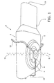
- a ventilating device 1 according to the present invention is shown in perspective bottom view.
- the ventilating device 1 comprises a housing 2 provided with an air outflow channel 3 and a casing 4 having an oval cross-section and a rectangular longitudinal section, at least if the outflow direction of the ventilating device is regarded as being the longitudinal direction.
- the casing 4 is provided with a circular opening 5, through which a motor 6 extends, which motor can be mounted to the ceiling (not shown), for example, by means of support arms 10.
- the ventilating device 1 comprises a casing 4 having an upper wall 4a, a lower wall 4b and two side walls 4c, within which an impeller wheel 13 having a radius R and a width b is accommodated.
- the impeller wheel 13 is connected, via a rotary shaft 14, to the motor 6, which extends through the opening 5 and which is connected to the support arms 10.
- the motor 6 rotatably drives the rotary shaft 14 for rotating the impeller wheel 13. Air is sucked into the casing 4 from outside through the opening 5, as indicated by the arrows i. From the opening 5 the air then flows further into the casing between the upper wall 4a and the lower wall 4b of the casing 4 and the impeller wheel 13, as indicated by the arrows i. The air is subsequently blown towards the side walls 4c of the casing by the impeller wheel 13, as indicated by the arrows u, and will subsequently exit the ventilating device 1 through an outlet opening 18 (see figure 1 ) on the side facing towards the viewer.
- the air flowing towards the side walls 4c will encounter practically no obstruction, if any, from (abrupt) transitions that might interfere with or even block the air flow.
- the rate of flow of the air can be optimised.
- the impeller wheel 13 has a radius R and a width b, and thus an effective circumferential area of 2 ⁇ R b.
- the casing 4 is further so configured that the cross-sectional area within the casing 4, minus the cross-sectional area of the impeller wheel, approximately equals the circumferential area of the centrifugal fan (2 ⁇ R b).
- the air flow area in the dot-hatched part in figure 2 is approximately the same size, at least near the cross-section at the axis of rotation of the centrifugal fan, as the surface area of the centrifugal fan 13 by means of which the air flow is generated.
- a ventilating device has been discussed and shown only by way of non-limitative example.
- the figures and the description of the illustrated embodiment do not have any limitative effect on the scope of the present invention, which is to be defined by the appended claims.
- the fan need not be provided in the centre of the casing, as shown in the figures, but it may be disposed eccentrically, so that the distance between one side wall and the impeller wheel is larger than the distance between the other side wall and the impeller wheel, for example.
- the outlet opening might also be located off-centre in the casing in that case.
- the casing is shown to have side walls having a semicircular cross-section, but it is also possible to use a different cross-sectional shape, taking into account, however, that the transition between the upper and lower walls and the side walls is preferably a gradual transition. It is furthermore also possible, of course, to use impeller wheels having a different shape within the centrifugal fan.
Landscapes
- Engineering & Computer Science (AREA)
- Mechanical Engineering (AREA)
- General Engineering & Computer Science (AREA)
- Structures Of Non-Positive Displacement Pumps (AREA)
Abstract
Description
- The present invention relates to a ventilating device comprising a centrifugal fan having a radius and a width, measured in the direction parallel to the axis of rotation of the centrifugal fan, and a housing having an at least substantially rectangular upper and lower wall extending at least substantially perpendicular to the axis of rotation on either side of the centrifugal fan and two side walls extending between said upper wall and said lower wall, and at the front side at least one outlet opening for an air flow to be generated by the centrifugal fan, which is at least substantially symmetrical relative to the perpendicular projection of the axis of rotation on the front side of the housing. Fans of such a type are used for building up essentially only a dynamic pressure, wherein air is blown from the outlet opening in a desired direction, frequently in combination with an outflow channel, for generating a directed air flow in a space in which the fan is suspended. This in contrast to ventilating devices comprising a so-called volute having an eccentrically disposed, relative to the impeller, relatively small outlet opening, by means of which also a substantial static pressure is built up.
- Such a ventilating device is known from
EP 1 267 132 - The inventor has discovered that the efficiency of the known ventilating device is not optimal, because undesirable swirls are created upon rotation of the impeller wheel in the housing, which swirls will eventually have an adverse effect on the outflow velocity of air through the outlet opening.
- Consequently it is an object of the present invention to improve the efficiency of the ventilating device as referred to in the introduction by providing an improved geometry of the housing of the ventilating device. According to the present invention, this object is accomplished in that the side walls extend at least partially in an outwardly curved line between the upper wall and the lower wall. Where mention is made of an outwardly curved line, this is understood to mean that at least part of a side wall extends outside a straight line, or the plane formed by a set of such straight lines, between the connections of the respective side wall to the upper and lower wall of the housing, and which thus extends substantially perpendicular to the upper wall and the lower wall. In this way an improved guide surface for guiding air that is blown towards the side walls and the front and rear sides in the housing in the direction of the outlet opening, which leads to a reduced occurrence of swirls in comparison with the known, substantially rectangular casing is provided. In situations in which the conditions are otherwise identical, this will result in a higher outflow velocity than with the known ventilating device.
- To prevent the occurrence of at least substantially acute angles which might have an adverse effect on the air flow, it is preferable if the side walls merge at least substantially gradually with the upper and lower wall at the location of a connection with the respective upper and lower wall.
- A housing having a very advantageous geometry is provided if the side walls have an at least substantially semicircular section. If the upper and lower wall extend parallel to each other in line with said semicircular wall, a very advantageous wall shape is provided, which makes it possible to realise a very efficient guidance of the air flow.
- It is preferable if the ventilating device has a central cross-section through the central axis of the centrifugal fan and at least substantially perpendicular to the outflow direction of an air flow to be generated by the centrifugal fan, which cross-section of the housing is oval in shape. One embodiment of such a geometry has already been discussed in the preceding paragraph, but also other oval sectional shapes are possible.
- In a preferred embodiment of the present invention, the centrifugal fan has a circumferential area which extends across the width b of the centrifugal fan, and the housing has a flow area, which is defined as the surface area within the housing of said central cross-section minus the surface area of the centrifugal fan in said central cross-section, wherein the surface area ratio between the circumferential area of the centrifugal fan and the flow area ranges between 0.75 and 1.5. The circumferential area can be defined as 2π x r x b, where r is the radius of the centrifugal fan and b is the width of the centrifugal fan. The flow area is in fact that part of the central cross-section through which air can freely flow without being obstructed by an obstacle, such as the centrifugal fan. A surface area ratio ranging between 0.75 and 1.5 leads to a high efficiency of the ventilating device.
- The efficiency of the ventilating device is enhanced in particular if the surface area ratio ranges between 0.9 and 1.15, and preferably at least substantially equals 1.
- The outlet opening of the ventilating device according to the present invention is preferably oval in shape. In an oval opening, the air flow generated by the centrifugal fan will encounter only a limited resistance.
- The housing preferably comprises a reduced diameter portion in the direction of an air flow to be generated by the ventilating device. The presence of the reduced diameter portion, preferably exhibiting a gradually reduced diameter, leads to a further buildup of the dynamic pressure, which contributes towards obtaining a strong air flow from the ventilating device.
- In order to be able to adequately direct an air flow to be generated by the ventilating device, the fan preferably comprises an outflow channel which extends from the reduced diameter portion towards the outlet opening.
- A very advantageous effect is achieved if the outflow channel has an at least substantially constant cross-section. Thus, an air flow exhibiting a minimal deflection is generated.
- The present invention will now be explained in more detail by means of a description of a preferred embodiment, in which reference is made to the appended drawings, in which:
-
Figure 1 is a perspective bottom view of a ventilating device according to the present invention; and -
Figure 2 is a cross-sectional view along the plane II-II of the ventilating devicefigure 1 . - With reference to
figure 1 , aventilating device 1 according to the present invention is shown in perspective bottom view. Theventilating device 1 comprises ahousing 2 provided with anair outflow channel 3 and acasing 4 having an oval cross-section and a rectangular longitudinal section, at least if the outflow direction of the ventilating device is regarded as being the longitudinal direction. At its bottom side, thecasing 4 is provided with acircular opening 5, through which amotor 6 extends, which motor can be mounted to the ceiling (not shown), for example, by means of supportarms 10. - Now referring to
figure 2 , there is shown a cross-sectional view along the plane II-II of thecasing 4 offigure 1 . Theventilating device 1 comprises acasing 4 having anupper wall 4a, alower wall 4b and twoside walls 4c, within which animpeller wheel 13 having a radius R and a width b is accommodated. Theimpeller wheel 13 is connected, via arotary shaft 14, to themotor 6, which extends through theopening 5 and which is connected to thesupport arms 10. - With reference now to both figures, and in particular
figure 2 , the operation of theventilating device 1 according to the present invention will now be explained in more detail. In use, themotor 6 rotatably drives therotary shaft 14 for rotating theimpeller wheel 13. Air is sucked into thecasing 4 from outside through theopening 5, as indicated by the arrows i. From theopening 5 the air then flows further into the casing between theupper wall 4a and thelower wall 4b of thecasing 4 and theimpeller wheel 13, as indicated by the arrows i. The air is subsequently blown towards theside walls 4c of the casing by theimpeller wheel 13, as indicated by the arrows u, and will subsequently exit theventilating device 1 through an outlet opening 18 (seefigure 1 ) on the side facing towards the viewer. As a result of the gradual transition from the flat upper andlower walls respective side walls 4c, the air flowing towards theside walls 4c will encounter practically no obstruction, if any, from (abrupt) transitions that might interfere with or even block the air flow. As a result of the gradual transition, the rate of flow of the air can be optimised. - The
impeller wheel 13 has a radius R and a width b, and thus an effective circumferential area of 2 π R b. Thecasing 4 is further so configured that the cross-sectional area within thecasing 4, minus the cross-sectional area of the impeller wheel, approximately equals the circumferential area of the centrifugal fan (2 π R b). In other words, the air flow area in the dot-hatched part infigure 2 is approximately the same size, at least near the cross-section at the axis of rotation of the centrifugal fan, as the surface area of thecentrifugal fan 13 by means of which the air flow is generated. When such a ratio is used, it is possible to develop an optimum rate of flow within the fan for maximising the outflow velocity of air through the outlet opening 18 in conditions that are otherwise unchanged. - In this document, a ventilating device according to the present invention has been discussed and shown only by way of non-limitative example. The figures and the description of the illustrated embodiment do not have any limitative effect on the scope of the present invention, which is to be defined by the appended claims. Several modifications can be realised by those skilled in the art without departing from the scope of the present invention. Thus, the fan need not be provided in the centre of the casing, as shown in the figures, but it may be disposed eccentrically, so that the distance between one side wall and the impeller wheel is larger than the distance between the other side wall and the impeller wheel, for example. The outlet opening might also be located off-centre in the casing in that case. Furthermore, in the figures the casing is shown to have side walls having a semicircular cross-section, but it is also possible to use a different cross-sectional shape, taking into account, however, that the transition between the upper and lower walls and the side walls is preferably a gradual transition. It is furthermore also possible, of course, to use impeller wheels having a different shape within the centrifugal fan.
Claims (11)
- A ventilating device comprising a centrifugal fan having a radius and a width, measured in the direction parallel to the axis of rotation of the centrifugal fan, and a housing having an at least substantially rectangular upper and lower wall extending at least substantially perpendicular to the axis of rotation on either side of the centrifugal fan and two side walls extending between said upper wall and said lower wall, and at the front side at least one outlet opening for an air flow to be generated by the centrifugal fan, which is at least substantially symmetrical relative to the perpendicular projection of the axis of rotation on the front side of the housing, characterised in that the side walls extend at least partially in an outwardly curved line between the upper wall and the lower wall.
- A ventilating device according to claim 1, characterised in that the side walls merge at least substantially gradually with the upper and lower wall at the location of a connection with the respective upper and lower wall.
- A ventilating device according to one or both of the preceding claims, characterised in that the side walls have an at least substantially semicircular section.
- A ventilating device according to any one or more of the preceding claims, characterised in that the ventilating device has a central cross-section through the central axis of the centrifugal fan and at least substantially perpendicular to the outflow direction of an air flow to be generated by the centrifugal fan, which cross-section of the housing is oval in shape.
- A ventilating device according to any one or more of the preceding claims, characterised in that the centrifugal fan has a circumferential area which extends across the width b of the centrifugal fan, and the housing has a flow area, which is defined as the surface area within the housing of said central cross-section minus the surface area of the centrifugal fan in said central cross-section, wherein the surface area ratio between the circumferential area of the centrifugal fan and the flow area ranges between 0.75 and 1.5.
- A ventilating device according to claim 5, characterised in that the surface area ratio ranges between 0.9 and 1.15.
- A ventilating device according to claim 6, characterised in that the surface area ratio at least substantially equals 1.
- A ventilating device according to any one or more of the preceding claims, characterised in that the outlet opening is at least substantially oval in shape.
- A ventilating device according to any one or more of the preceding claims, characterised in that housing comprises a reduced diameter portion in the direction of an air flow to be generated by the ventilating device.
- A ventilating device according to claim 9, characterised in that the fan comprises an outflow channel which extends from the reduced diameter portion towards the outlet opening.
- A ventilating device according to claim 10, characterised in that the outflow channel has an at least substantially constant cross-section.
Applications Claiming Priority (1)
| Application Number | Priority Date | Filing Date | Title |
|---|---|---|---|
| NL1034927A NL1034927C2 (en) | 2008-01-18 | 2008-01-18 | Efficient fan device with centrifugal fan. |
Publications (2)
| Publication Number | Publication Date |
|---|---|
| EP2080911A2 true EP2080911A2 (en) | 2009-07-22 |
| EP2080911A3 EP2080911A3 (en) | 2011-12-14 |
Family
ID=39758516
Family Applications (1)
| Application Number | Title | Priority Date | Filing Date |
|---|---|---|---|
| EP09000411A Withdrawn EP2080911A3 (en) | 2008-01-18 | 2009-01-14 | Efficient ventilating device comprising a centrifugal fan |
Country Status (2)
| Country | Link |
|---|---|
| EP (1) | EP2080911A3 (en) |
| NL (1) | NL1034927C2 (en) |
Citations (1)
| Publication number | Priority date | Publication date | Assignee | Title |
|---|---|---|---|---|
| EP1267132A1 (en) | 2001-06-13 | 2002-12-18 | Ce2S N.V. | Ventilating device and ventilating system fitted therewith |
Family Cites Families (4)
| Publication number | Priority date | Publication date | Assignee | Title |
|---|---|---|---|---|
| US1745253A (en) * | 1927-09-26 | 1930-01-28 | Charles O Granberg | Blower |
| US1966262A (en) * | 1928-09-22 | 1934-07-10 | Maine Electric Company | Blower |
| DE1300623B (en) * | 1959-10-06 | 1969-08-07 | Danieels Warmte En Kunststofte | Housing made of plastic for a centrifugal fan |
| DE2215473C3 (en) * | 1972-03-29 | 1980-12-18 | Standard Elektrik Lorenz Ag, 7000 Stuttgart | Self-vibration damped, low-noise radial fan |
-
2008
- 2008-01-18 NL NL1034927A patent/NL1034927C2/en not_active IP Right Cessation
-
2009
- 2009-01-14 EP EP09000411A patent/EP2080911A3/en not_active Withdrawn
Patent Citations (1)
| Publication number | Priority date | Publication date | Assignee | Title |
|---|---|---|---|---|
| EP1267132A1 (en) | 2001-06-13 | 2002-12-18 | Ce2S N.V. | Ventilating device and ventilating system fitted therewith |
Also Published As
| Publication number | Publication date |
|---|---|
| NL1034927C2 (en) | 2009-07-21 |
| EP2080911A3 (en) | 2011-12-14 |
Similar Documents
| Publication | Publication Date | Title |
|---|---|---|
| JP6143596B2 (en) | Centrifugal blower and vehicle air conditioner equipped with the centrifugal blower | |
| CN102959250B (en) | Multi-blade centrifugal fan and air conditioner using the multi-blade centrifugal fan | |
| US8231331B2 (en) | Reduction of flow-induced noise in a centrifugal blower | |
| JP2011099413A (en) | Multi-blade centrifugal fan, and air conditioner using the same | |
| JP5145188B2 (en) | Multiblade centrifugal fan and air conditioner using the same | |
| JPWO2018003017A1 (en) | Electric blower and vacuum cleaner | |
| CN102365465A (en) | Air blowing device | |
| JP2009287427A (en) | Centrifugal blower | |
| JP2008232049A (en) | Centrifugal impeller and centrifugal blower | |
| JP2007205269A (en) | Centrifugal fan | |
| JP4910809B2 (en) | Centrifugal blower | |
| KR101249841B1 (en) | Axial fan assembly | |
| KR20170059240A (en) | Local ventilator | |
| JP4670285B2 (en) | Impeller and blower fan having the same | |
| JP5879486B2 (en) | Blower | |
| JP2008031982A (en) | Multi-blade fan | |
| JP2011226407A (en) | Multi-blade fan, air conditioner, and guide member | |
| JP2010270750A (en) | Electric blower, vacuum cleaner equipped with the same, and method for manufacturing the same | |
| JP5008386B2 (en) | Centrifugal multiblade blower | |
| JP4727425B2 (en) | Centrifugal impeller and clean system equipped with it | |
| JP5899394B2 (en) | Centrifugal blower | |
| JP4606005B2 (en) | Electric blower | |
| JP2009013923A (en) | Centrifugal blower | |
| JP2874600B2 (en) | Centripetal blower | |
| KR200332249Y1 (en) | High efficiency and low noise type centrifugal fan |
Legal Events
| Date | Code | Title | Description |
|---|---|---|---|
| PUAI | Public reference made under article 153(3) epc to a published international application that has entered the european phase |
Free format text: ORIGINAL CODE: 0009012 |
|
| AK | Designated contracting states |
Kind code of ref document: A2 Designated state(s): AT BE BG CH CY CZ DE DK EE ES FI FR GB GR HR HU IE IS IT LI LT LU LV MC MK MT NL NO PL PT RO SE SI SK TR |
|
| AX | Request for extension of the european patent |
Extension state: AL BA RS |
|
| PUAL | Search report despatched |
Free format text: ORIGINAL CODE: 0009013 |
|
| AK | Designated contracting states |
Kind code of ref document: A3 Designated state(s): AT BE BG CH CY CZ DE DK EE ES FI FR GB GR HR HU IE IS IT LI LT LU LV MC MK MT NL NO PL PT RO SE SI SK TR |
|
| AX | Request for extension of the european patent |
Extension state: AL BA RS |
|
| RIC1 | Information provided on ipc code assigned before grant |
Ipc: F04D 29/42 20060101AFI20111109BHEP |
|
| AKY | No designation fees paid | ||
| REG | Reference to a national code |
Ref country code: DE Ref legal event code: R108 |
|
| REG | Reference to a national code |
Ref country code: DE Ref legal event code: R108 Effective date: 20120822 |
|
| STAA | Information on the status of an ep patent application or granted ep patent |
Free format text: STATUS: THE APPLICATION IS DEEMED TO BE WITHDRAWN |
|
| 18D | Application deemed to be withdrawn |
Effective date: 20120615 |