EP2080879A2 - Mounting system for a gas turbine engine - Google Patents
Mounting system for a gas turbine engine Download PDFInfo
- Publication number
- EP2080879A2 EP2080879A2 EP09250067A EP09250067A EP2080879A2 EP 2080879 A2 EP2080879 A2 EP 2080879A2 EP 09250067 A EP09250067 A EP 09250067A EP 09250067 A EP09250067 A EP 09250067A EP 2080879 A2 EP2080879 A2 EP 2080879A2
- Authority
- EP
- European Patent Office
- Prior art keywords
- thrust
- gas turbine
- turbine engine
- recited
- loads
- Prior art date
- Legal status (The legal status is an assumption and is not a legal conclusion. Google has not performed a legal analysis and makes no representation as to the accuracy of the status listed.)
- Granted
Links
- 239000007789 gas Substances 0.000 description 46
- 230000003068 static effect Effects 0.000 description 8
- 230000008901 benefit Effects 0.000 description 3
- 230000005540 biological transmission Effects 0.000 description 2
- 238000010586 diagram Methods 0.000 description 2
- 239000000446 fuel Substances 0.000 description 2
- 239000000567 combustion gas Substances 0.000 description 1
- 239000000284 extract Substances 0.000 description 1
- 238000000034 method Methods 0.000 description 1
- 238000012986 modification Methods 0.000 description 1
- 230000004048 modification Effects 0.000 description 1
- 238000011144 upstream manufacturing Methods 0.000 description 1
Images


Classifications
-
- B—PERFORMING OPERATIONS; TRANSPORTING
- B64—AIRCRAFT; AVIATION; COSMONAUTICS
- B64D—EQUIPMENT FOR FITTING IN OR TO AIRCRAFT; FLIGHT SUITS; PARACHUTES; ARRANGEMENTS OR MOUNTING OF POWER PLANTS OR PROPULSION TRANSMISSIONS IN AIRCRAFT
- B64D27/00—Arrangement or mounting of power plant in aircraft; Aircraft characterised thereby
- B64D27/02—Aircraft characterised by the type or position of power plant
- B64D27/16—Aircraft characterised by the type or position of power plant of jet type
- B64D27/18—Aircraft characterised by the type or position of power plant of jet type within or attached to wing
-
- B64D27/40—
-
- F—MECHANICAL ENGINEERING; LIGHTING; HEATING; WEAPONS; BLASTING
- F02—COMBUSTION ENGINES; HOT-GAS OR COMBUSTION-PRODUCT ENGINE PLANTS
- F02C—GAS-TURBINE PLANTS; AIR INTAKES FOR JET-PROPULSION PLANTS; CONTROLLING FUEL SUPPLY IN AIR-BREATHING JET-PROPULSION PLANTS
- F02C7/00—Features, components parts, details or accessories, not provided for in, or of interest apart form groups F02C1/00 - F02C6/00; Air intakes for jet-propulsion plants
- F02C7/20—Mounting or supporting of plant; Accommodating heat expansion or creep
Definitions
- This disclosure generally relates to a gas turbine engine, and more particularly to a mounting system for mounting a gas turbine engine to an aircraft pylon.
- a gas turbine engine may be mounted at various points of an aircraft, such as a pylon integrated with an aircraft structure.
- a mounting system is often used to support a gas turbine engine relative to the pylon.
- Mounting systems may include any combination of links, ball joints or plates that support the engine vertically, laterally and axially.
- the mounting system ensures the transmission of a variety of static and dynamic loads between the engine and the aircraft structure.
- the loads experienced by a mounting system include vertical loads and side loads (loads experienced perpendicular to an engine centerline axis), torque loads (loads experienced as a result of rotation of the engine) and thrust loads (loads experienced in a direction parallel to aircraft travel).
- the mounting system must also absorb the deformations that the engine is subjected to during different flight conditions and the dimensional variations caused by thermal expansion and retraction of the engine.
- One known mounting system for a gas turbine engine includes a pylon having a forward mount and an aft mount.
- the forward mount dissipates thrust loads, vertical loads and side loads experienced adjacent to the front end of the engine.
- the aft mount dissipates vertical loads, side loads, thrust loads and torque loads experienced adjacent to the rear end of the engine.
- a mounting system for a gas turbine engine in accordance with one aspect of the invention includes a thrust ring and a linkage assembly.
- the linkage assembly is at least partially received by the thrust ring.
- the linkage assembly reacts at least a side load and a thrust load communicated from the thrust ring.
- a gas turbine engine in accordance with a further aspect of the invention includes a compressor section, a combustor section, a turbine section, a pylon and a mounting system.
- the mounting system includes a front mount and a rear mount that each extend from the pylon.
- the rear mount includes a thrust ring and a thrust tripod that is at least partially received by the thrust ring.
- a method of mounting a gas turbine engine in accordance with a further aspect of the invention includes positioning a thrust ring about a turbine section, receiving at least a portion of a linkage assembly within the thrust ring, and reacting at least a side load and a thrust load of the gas turbine engine from the thrust ring to the linkage assembly.
- Figure 1 illustrates a gas turbine engine 10 suspended from an engine pylon 12 as is typical of an aircraft designed for subsonic operation.
- the gas turbine engine 10 is a turbofan gas turbine engine.
- the gas turbine engine 10 includes a fan section 14, a compressor section 16 having a low pressure compressor 18 and a high pressure compressor 20, a combustor section 22, and a turbine section 24 having a high pressure turbine 26 and a low pressure turbine 28.
- a low speed shaft 30 rotationally supports the low pressure compressor 18 and the low pressure turbine 28.
- the low speed shaft 30 also drives the fan section 14 either directly or through a gear train 34, for example.
- a high speed shaft 32 rotationally supports the high pressure compressor 20 and the high pressure turbine 26.
- the low speed shaft 30 and the high speed shaft 32 rotate about a longitudinal centerline axis A of the gas turbine engine 10.
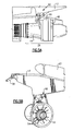
- FIG. 2 illustrates an engine static case structure 36 of the example gas turbine engine 10.
- the engine static case structure 36 generally includes a fan case 38, an intermediate case (IMC) 40, a high pressure compressor case 42, a diffuser case 44, a low pressure turbine case 46 and a turbine exhaust case 48.
- the fan section 14 includes a plurality of circumferentially spaced fan blades 50 that are surrounded by the fan case 38.
- the turbine section 24 includes a mid-turbine frame (MTF) 52 that includes a plurality of radially extending structural struts 54 that are preloaded in tension.
- the MTF 52 provides aft structural support within the diffuser case 44 and rotatably supports the low speed shaft 30 and the high speed shaft 32.
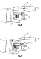
- FIG 3 illustrates an example mounting system 56 for mounting the gas turbine engine 10 to an aircraft structure, such as an aircraft wing 57, that includes the pylon 12.
- the mounting system 56 includes a front mount 58 and a rear mount 60.
- the front mount 58 is secured to the IMC 40.
- the front mount 58 is secured to the core engine, such as a portion of the compressor section 16, for example (See Figure 4 ).
- a person of ordinary skill in the art having the benefit of this disclosure would be able to select an appropriate mounting location for the front mount 58.
- the front mount 58 distributes and dissipates engine loads about the gas turbine engine 10. For example, the front mount 58 reacts both vertical loads and side loads experienced by the gas turbine engine 10. Vertical loads are loads created by the weight of the gas turbine engine 10. Side loads are engine loads that are created through crosswinds or maneuvering of the gas turbine engine 10. Both the vertical loads and the side loads are perpendicular to the longitudinal centerline axis A of the gas turbine engine 10.
- the term "reacts" as utilized in this disclosure is defined as absorbing a load and dissipating the load to another location of the gas turbine engine 10.
- the front mount 58 reacts the vertical loads and side loads from a front end of the gas turbine engine 10 to the pylon 12.
- the front mount 58 is a shackle arrangement and includes a generally plate-like member that is fastened to connect the front mount 58 to the pylon 12 and a portion of the gas turbine engine 10.
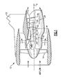
- FIGs 5A and 5B illustrate an example rear mount 60 of the mounting system 56.
- the rear mount 60 is secured to the diffuser case 44 of the gas turbine engine 10.
- the rear mount 60 is secured adjacent to the MTF 52 of the turbine section 24 (see Figure 5B ).
- the rear mount 60 is secured to the gas turbine engine 10 adjacent to the turbine exhaust case 48. It should be understood that the rear mount 60 may alternatively be mounted at any other region of the gas turbine engine 10.
- the rear mount 60 includes a thrust ring 62, a linkage assembly 64, and linkage arms 66.
- the thrust ring 62 is positioned between the diffuser case 44 and the low pressure turbine case 46.
- the thrust ring 62 extends circumferentially about the turbine section 24 over a range of 360°. That is, the thrust ring 62 entirely surrounds a portion of the gas turbine engine 10 and is shaped to distribute the thrust loads that act upon the engine 10 from a widespread area of the engine to a single point, as is further discussed below.
- the example thrust ring 62 is illustrated as a separate component, it should be understood that the thrust ring 62 may be formed integrally with a portion of the engine static case structure 36 or other engine mounting equipment, for example.
- the thrust ring 62 includes a cup 70 having a ball mount 72.
- the ball mount 72 transversely protrudes from the thrust ring 62 in an upstream direction.
- the cup 70 and the ball mount 72 of the thrust ring 62 receive a lower portion of the linkage assembly 64, as is further discussed below.
- the linkage assembly 64 is a thrust tripod that is generally Y-shaped, in one example.
- the linkage assembly 64 includes a pin 74, a pair of opposing side load arms 76 and a thrust joint 68.
- the example linkage assembly 64 is illustrated as having a tripod configuration, it should be understood that the linkage assembly 64 could be configured with any number and design of linkages that interact with the thrust ring 62 to react loads.
- the pin 74 is positioned vertically relative to the gas turbine engine 10 (where the rear mount 60 is assembled) (See Figures 5A and 5B ).
- the pin 74 is received within the ball mount 72 of the cup 70 of the thrust ring 62.
- the thrust ring 62 communicates thrust loads directly to the pin 74.
- the pin 74 is slideably received within the ball mount 72 to allow for thermal growth of the gas turbine engine 10 and to dissipate the engine loads that are concentrated at the pin 74 to the other components of the rear mount 60. That is, because the pin 74 is free to move within the cup 70, the engine loads experienced at the pin 74 may be communicated to other portions of the rear mount 60 thereby reducing the amount of stress localized at the pin 74.
- the side load arms 76 transversely protrude from the pin 74. In one example, the side load arms 76 extend at opposite directions from the pin 74 at an equivalent angle. Each side load arm 76 is attached to the pylon 12, such as by bolting the side load arm 76 thereto, for example.
- the thrust joint 68 protrudes from the pin 74 in an aftward direction relative to the gas turbine engine 10.
- the thrust joint 68 is angled relative to the pin 74.
- the actual angle of the thrust joint 68 relative to the pin 74 will vary depending upon design specific parameters including, but not limited to, the location of the pylon 12 rear mount 60 interface.
- a thrust link 78 is connected to the thrust joint 68 on one end, and is connected to the pylon 12 at an opposite end.
- the thrust link 78 is bolted to both the thrust joint 68 and the pylon 12, in one example.
- the rear mount 60 also includes linkage arms 66 that extend between the turbine section 24 and the pylon 12.
- the linkage arms 66 extend from the diffuser case 44 to the pylon 12.
- the diffuser case 44 includes a flange 80 having fastening linkages 82 for bolting the linkage arms 66 thereto.
- the linkage arms 66 are fastened to the pylon 12 at an opposite end of the linkage arm 66 from the fastening linkages 82, such as by bolting, for example.
- the linkage arms 66 retain the vertical positioning of the gas turbine engine 10 relative to the pylon 12.
- the linkage arms 66 are connected to the diffuser case 44 and the connections are spaced apart by approximately 180° on the diffuser case 44. A spacing of 180° minimizes ovalization distortion created by transmitting mount loads to the MTF 52. It should be understood that other mounting locations and spacing configurations for the linkage arms 66 are contemplated as within the scope of this disclosure.
- FIG 7 is a free body diagram that schematically illustrates a variety of engine loads that are reacted by the example mounting system 56.
- the front mount 58 is operable to react both vertical loads V and side loads S that act adjacent to a forward end of the gas turbine engine 10.
- Vertical loads V are loads created by the weight of the gas turbine engine 10.
- Side loads S are engine loads that are created through crosswinds or maneuvering of the gas turbine engine 10. Both the vertical loads V and the side loads S act upon the engine 10 in directions that are perpendicular to the longitudinal centerline axis A of the gas turbine engine 10.
- the vertical loads V and the side loads S are absorbed by the front mount 58 and communicated from the core engine to the pylon 12.
- the front mount 58 is not required to react thrust loads of the gas turbine engine 10.
- the rear mount 60 reacts thrust loads T, side loads S, vertical loads V and torque loads Q.
- Thrust loads T are loads experienced by the gas turbine engine 10 that occur parallel to the engine longitudinal centerline axis A and occur during propulsion of the aircraft.
- Torque loads Q are loads that result from rotation of the internal components of the gas turbine engine 10 (and the side loads S and thrust loads T).
- the thrust ring 62 supports a thrust load T and a side load S.
- the thrust ring 62 communicates the thrust load T and the side loads S to the pin 74.
- the pin 74 also supports thrust loads T and side loads S.
- the side loads S that are reacted by the pin 74 are communicated to the side load arms 76 and subsequently dissipated into the pylon 12.
- the thrust load T experienced at the pin 74 is communicated from the linkage assembly 64, through the thrust link 68, and subsequently to the pylon 12.
- the linkage arms 66 support vertical loads V1 and V2, respectively, and the torque load Q.
- the linkage arms 66 also maintain the vertical positioning of the gas turbine engine 10 relative to the pylon 12.
- the vertical loads V1, V2 and the torque load Q are communicated from each linkage arm 66 directly to the pylon 12 to dissipate the loads.
Abstract
Description
- This disclosure generally relates to a gas turbine engine, and more particularly to a mounting system for mounting a gas turbine engine to an aircraft pylon.
- A gas turbine engine may be mounted at various points of an aircraft, such as a pylon integrated with an aircraft structure. For example, a mounting system is often used to support a gas turbine engine relative to the pylon. Mounting systems may include any combination of links, ball joints or plates that support the engine vertically, laterally and axially. The mounting system ensures the transmission of a variety of static and dynamic loads between the engine and the aircraft structure. The loads experienced by a mounting system include vertical loads and side loads (loads experienced perpendicular to an engine centerline axis), torque loads (loads experienced as a result of rotation of the engine) and thrust loads (loads experienced in a direction parallel to aircraft travel). The mounting system must also absorb the deformations that the engine is subjected to during different flight conditions and the dimensional variations caused by thermal expansion and retraction of the engine.
- One known mounting system for a gas turbine engine includes a pylon having a forward mount and an aft mount. The forward mount dissipates thrust loads, vertical loads and side loads experienced adjacent to the front end of the engine. The aft mount dissipates vertical loads, side loads, thrust loads and torque loads experienced adjacent to the rear end of the engine.
- One disadvantage of mounting systems of this type is the inability to adequately react (i.e., absorb and dissipate) the static (weight) loads and dynamic (maneuvering) loads created during operation of the engine as an engine distorts and flexes. The engine loads may distort the casing that surrounds the various engine components. This distortion can cause the clearances between the static cases and a plurality of rotating blade tips encased within the static cases to increase. This may negatively affect engine performance and increase fuel bum.
- Accordingly, it is desirable to provide a mounting system for a gas turbine engine that minimizes tip clearances and that adequately dissipates the transmission of loads between the engine and the aircraft structure.
- A mounting system for a gas turbine engine in accordance with one aspect of the invention includes a thrust ring and a linkage assembly. The linkage assembly is at least partially received by the thrust ring. The linkage assembly reacts at least a side load and a thrust load communicated from the thrust ring.
- A gas turbine engine in accordance with a further aspect of the invention includes a compressor section, a combustor section, a turbine section, a pylon and a mounting system. The mounting system includes a front mount and a rear mount that each extend from the pylon. The rear mount includes a thrust ring and a thrust tripod that is at least partially received by the thrust ring.
- A method of mounting a gas turbine engine in accordance with a further aspect of the invention includes positioning a thrust ring about a turbine section, receiving at least a portion of a linkage assembly within the thrust ring, and reacting at least a side load and a thrust load of the gas turbine engine from the thrust ring to the linkage assembly.
- The various features and advantages of this disclosure will become apparent to those skilled in the art from the following detailed description. The drawings that accompany the detailed description can be briefly described as follows.
-
-
Figure 1 illustrates a general sectional view of a gas turbine engine; -
Figure 2 illustrates a partial sectional view of an example gas turbine engine having an engine static case structure on the lower half thereof; -
Figure 3 illustrates an example mounting system for a gas turbine engine having a front mount at a first location; -
Figure 4 illustrates the example mounting system ofFigure 3 having a front mount at a second location; -
Figure 5A illustrates a side view of a rear mount of the example mounting system illustrated inFigures 3 and 4 ; -
Figure 5B illustrates an isometric view of the example rear mount illustrated inFigure 5A ; -
Figure 6 illustrates an exploded view of an example mounting system including a rear mount having a linkage assembly and a thrust ring; and -
Figure 7 illustrates a free body diagram illustrating loads reacted by the example mounting system ofFigures 3-7 . -
Figure 1 illustrates agas turbine engine 10 suspended from anengine pylon 12 as is typical of an aircraft designed for subsonic operation. In one example, thegas turbine engine 10 is a turbofan gas turbine engine. Thegas turbine engine 10 includes afan section 14, acompressor section 16 having alow pressure compressor 18 and ahigh pressure compressor 20, acombustor section 22, and aturbine section 24 having ahigh pressure turbine 26 and alow pressure turbine 28. Alow speed shaft 30 rotationally supports thelow pressure compressor 18 and thelow pressure turbine 28. Thelow speed shaft 30 also drives thefan section 14 either directly or through agear train 34, for example. Ahigh speed shaft 32 rotationally supports thehigh pressure compressor 20 and thehigh pressure turbine 26. Thelow speed shaft 30 and thehigh speed shaft 32 rotate about a longitudinal centerline axis A of thegas turbine engine 10. - During operation, airflow is drawn into the
gas turbine engine 10 by thefan section 14 and is pressurized in thecompressor section 16. Fuel is mixed with the pressurized air and combusted within thecombustor section 22. The combustion gases are discharged through theturbine section 24, which extracts energy therefrom for powering thecompressor section 16 and thefan section 14. Of course, this view is highly schematic. It should be understood that the features and example illustrations presented herein are not limited to a turbofan gas turbine engine. That is, the present disclosure is applicable to any engine architecture including a geared fan turbofan. -
Figure 2 illustrates an enginestatic case structure 36 of the examplegas turbine engine 10. The enginestatic case structure 36 generally includes a fan case 38, an intermediate case (IMC) 40, a highpressure compressor case 42, adiffuser case 44, a lowpressure turbine case 46 and aturbine exhaust case 48. Thefan section 14 includes a plurality of circumferentially spacedfan blades 50 that are surrounded by the fan case 38. - In one example, the
turbine section 24 includes a mid-turbine frame (MTF) 52 that includes a plurality of radially extendingstructural struts 54 that are preloaded in tension. The MTF 52 provides aft structural support within thediffuser case 44 and rotatably supports thelow speed shaft 30 and thehigh speed shaft 32. -
Figure 3 illustrates anexample mounting system 56 for mounting thegas turbine engine 10 to an aircraft structure, such as anaircraft wing 57, that includes thepylon 12. Themounting system 56 includes afront mount 58 and arear mount 60. In this example, thefront mount 58 is secured to the IMC 40. In another example, thefront mount 58 is secured to the core engine, such as a portion of thecompressor section 16, for example (SeeFigure 4 ). A person of ordinary skill in the art having the benefit of this disclosure would be able to select an appropriate mounting location for thefront mount 58. - The
front mount 58 distributes and dissipates engine loads about thegas turbine engine 10. For example, thefront mount 58 reacts both vertical loads and side loads experienced by thegas turbine engine 10. Vertical loads are loads created by the weight of thegas turbine engine 10. Side loads are engine loads that are created through crosswinds or maneuvering of thegas turbine engine 10. Both the vertical loads and the side loads are perpendicular to the longitudinal centerline axis A of thegas turbine engine 10. - The term "reacts" as utilized in this disclosure is defined as absorbing a load and dissipating the load to another location of the
gas turbine engine 10. For example, thefront mount 58 reacts the vertical loads and side loads from a front end of thegas turbine engine 10 to thepylon 12. In one example, thefront mount 58 is a shackle arrangement and includes a generally plate-like member that is fastened to connect thefront mount 58 to thepylon 12 and a portion of thegas turbine engine 10. -
Figures 5A and 5B illustrate an examplerear mount 60 of the mountingsystem 56. In one example, therear mount 60 is secured to thediffuser case 44 of thegas turbine engine 10. In another example, therear mount 60 is secured adjacent to theMTF 52 of the turbine section 24 (seeFigure 5B ). In yet another example, therear mount 60 is secured to thegas turbine engine 10 adjacent to theturbine exhaust case 48. It should be understood that therear mount 60 may alternatively be mounted at any other region of thegas turbine engine 10. - Referring to
Figure 6 , therear mount 60 includes athrust ring 62, alinkage assembly 64, andlinkage arms 66. In one example, thethrust ring 62 is positioned between thediffuser case 44 and the lowpressure turbine case 46. In another example, thethrust ring 62 extends circumferentially about theturbine section 24 over a range of 360°. That is, thethrust ring 62 entirely surrounds a portion of thegas turbine engine 10 and is shaped to distribute the thrust loads that act upon theengine 10 from a widespread area of the engine to a single point, as is further discussed below. Although theexample thrust ring 62 is illustrated as a separate component, it should be understood that thethrust ring 62 may be formed integrally with a portion of the enginestatic case structure 36 or other engine mounting equipment, for example. - The
thrust ring 62 includes acup 70 having aball mount 72. In the illustrated example, the ball mount 72 transversely protrudes from thethrust ring 62 in an upstream direction. Thecup 70 and the ball mount 72 of thethrust ring 62 receive a lower portion of thelinkage assembly 64, as is further discussed below. - The
linkage assembly 64 is a thrust tripod that is generally Y-shaped, in one example. Thelinkage assembly 64 includes apin 74, a pair of opposingside load arms 76 and a thrust joint 68. Although theexample linkage assembly 64 is illustrated as having a tripod configuration, it should be understood that thelinkage assembly 64 could be configured with any number and design of linkages that interact with thethrust ring 62 to react loads. - In one example, the
pin 74 is positioned vertically relative to the gas turbine engine 10 (where therear mount 60 is assembled) (SeeFigures 5A and 5B ). Thepin 74 is received within the ball mount 72 of thecup 70 of thethrust ring 62. Thethrust ring 62 communicates thrust loads directly to thepin 74. In this example, thepin 74 is slideably received within the ball mount 72 to allow for thermal growth of thegas turbine engine 10 and to dissipate the engine loads that are concentrated at thepin 74 to the other components of therear mount 60. That is, because thepin 74 is free to move within thecup 70, the engine loads experienced at thepin 74 may be communicated to other portions of therear mount 60 thereby reducing the amount of stress localized at thepin 74. - The
side load arms 76 transversely protrude from thepin 74. In one example, theside load arms 76 extend at opposite directions from thepin 74 at an equivalent angle. Eachside load arm 76 is attached to thepylon 12, such as by bolting theside load arm 76 thereto, for example. - The thrust joint 68 protrudes from the
pin 74 in an aftward direction relative to thegas turbine engine 10. In one example, the thrust joint 68 is angled relative to thepin 74. The actual angle of the thrust joint 68 relative to thepin 74 will vary depending upon design specific parameters including, but not limited to, the location of thepylon 12rear mount 60 interface. Athrust link 78 is connected to the thrust joint 68 on one end, and is connected to thepylon 12 at an opposite end. The thrust link 78 is bolted to both the thrust joint 68 and thepylon 12, in one example. - The
rear mount 60 also includeslinkage arms 66 that extend between theturbine section 24 and thepylon 12. In one example, thelinkage arms 66 extend from thediffuser case 44 to thepylon 12. In this example, thediffuser case 44 includes aflange 80 havingfastening linkages 82 for bolting thelinkage arms 66 thereto. Thelinkage arms 66 are fastened to thepylon 12 at an opposite end of thelinkage arm 66 from thefastening linkages 82, such as by bolting, for example. - The
linkage arms 66 retain the vertical positioning of thegas turbine engine 10 relative to thepylon 12. In one example, thelinkage arms 66 are connected to thediffuser case 44 and the connections are spaced apart by approximately 180° on thediffuser case 44. A spacing of 180° minimizes ovalization distortion created by transmitting mount loads to theMTF 52. It should be understood that other mounting locations and spacing configurations for thelinkage arms 66 are contemplated as within the scope of this disclosure. -
Figure 7 , with continuing reference toFigures 1-6 , is a free body diagram that schematically illustrates a variety of engine loads that are reacted by theexample mounting system 56. In this example, thefront mount 58 is operable to react both vertical loads V and side loads S that act adjacent to a forward end of thegas turbine engine 10. Vertical loads V are loads created by the weight of thegas turbine engine 10. Side loads S are engine loads that are created through crosswinds or maneuvering of thegas turbine engine 10. Both the vertical loads V and the side loads S act upon theengine 10 in directions that are perpendicular to the longitudinal centerline axis A of thegas turbine engine 10. The vertical loads V and the side loads S are absorbed by thefront mount 58 and communicated from the core engine to thepylon 12. In one example, thefront mount 58 is not required to react thrust loads of thegas turbine engine 10. - In this example, the
rear mount 60 reacts thrust loads T, side loads S, vertical loads V and torque loads Q. Thrust loads T are loads experienced by thegas turbine engine 10 that occur parallel to the engine longitudinal centerline axis A and occur during propulsion of the aircraft. Torque loads Q are loads that result from rotation of the internal components of the gas turbine engine 10 (and the side loads S and thrust loads T). - The
thrust ring 62 supports a thrust load T and a side load S. Thethrust ring 62 communicates the thrust load T and the side loads S to thepin 74. Thepin 74 also supports thrust loads T and side loads S. The side loads S that are reacted by thepin 74 are communicated to theside load arms 76 and subsequently dissipated into thepylon 12. The thrust load T experienced at thepin 74 is communicated from thelinkage assembly 64, through thethrust link 68, and subsequently to thepylon 12. - The
linkage arms 66 support vertical loads V1 and V2, respectively, and the torque load Q. Thelinkage arms 66 also maintain the vertical positioning of thegas turbine engine 10 relative to thepylon 12. The vertical loads V1, V2 and the torque load Q are communicated from eachlinkage arm 66 directly to thepylon 12 to dissipate the loads. - The foregoing description shall be interpreted as illustrative and not in any limiting sense. A worker of ordinary skill in the art having the benefit of this disclosure would recognize that certain modifications would come within the scope of the disclosure. For these reasons, the following claims should be studied to determine the true scope and content of this disclosure.
Claims (15)
- A mounting system (56) for a gas turbine engine, comprising:a thrust ring (62); anda linkage assembly (64) at least partially received by said thrust ring (62), wherein said linkage assembly (64) reacts at least a side load (S) and a thrust load (T) communicated from said thrust ring (62).
- The system as recited in claim 1, wherein said thrust ring (62) includes a cup (70) having a ball mount (72), and a pin (74) of said linkage assembly (64) is slideably received within said cup (70).
- The system as recited in claim 1 or 2, wherein said linkage assembly (64) is a thrust tripod that includes a pin (74), at least two side-load arms (76), and a thrust joint (68).
- The system as recited in claim 3, wherein said at least two side-load arms (76) transversely extend from said pin (74), and said thrust tripod is generally Y-shaped.
- The system as recited in claim 3 or 4, wherein said thrust joint (68) extends in an aft direction from said pin (74) relative to the gas turbine engine (10).
- The system as recited in claim 5, wherein said thrust joint (68) is angled relative to said pin (74), and including a thrust link (78) attached to said thrust joint (68).
- The system as recited in any preceding claim, comprising at least one linkage arm (66) that vertically supports the gas turbine engine (10).
- A gas turbine engine (10), comprising:a compressor section (16), a combustor section (22), and a turbine section (24);a pylon (12);a mounting system (56) including a front mount (58) and a rear mount (60) each extending from said pylon (12), wherein said rear mount (60) includes a thrust ring (62) and a thrust tripod (64) at least partially received by said thrust ring (62).
- The gas turbine engine as recited in claim 8, wherein said front mount (58) is attached to a fan section (14) of said gas turbine engine (10).
- The gas turbine engine as recited in claim 8, wherein said front mount (58) is attached to said compressor section (16) of said gas turbine engine (10).
- The gas turbine engine as recited in claim 8, 9 or 10, wherein said thrust ring (62) extends circumferentially about a portion of said turbine section (24) over a range of 360 degrees.
- The gas turbine engine as recited in any of claims 8 to 11, wherein said thrust ring (62) is positioned between a diffuser case (44) and a low pressure turbine case (46) of said turbine section (24).
- The gas turbine engine as recited in any of claims 8 to 12, wherein said thrust tripod (64) reacts at least a side load (S) and a thrust load (T) communicated from said thrust ring (62).
- The gas turbine engine as recited in any of claims 8 to 13, wherein said thrust tripod (64) includes a pin (74), at least two side-load arms (76), and a thrust joint (68).
- The gas turbine engine as recited in any of claims 8 to 14, wherein said rear mount (60) includes at least two linkage arms (66) connected between said turbine section (24) and said pylon (12) to vertically support said gas turbine engine (10) and to react torque loads of said gas turbine engine (10).
Applications Claiming Priority (1)
| Application Number | Priority Date | Filing Date | Title |
|---|---|---|---|
| US12/016,337 US8118251B2 (en) | 2008-01-18 | 2008-01-18 | Mounting system for a gas turbine engine |
Publications (3)
| Publication Number | Publication Date |
|---|---|
| EP2080879A2 true EP2080879A2 (en) | 2009-07-22 |
| EP2080879A3 EP2080879A3 (en) | 2012-05-09 |
| EP2080879B1 EP2080879B1 (en) | 2016-05-18 |
Family
ID=40352704
Family Applications (1)
| Application Number | Title | Priority Date | Filing Date |
|---|---|---|---|
| EP09250067.7A Active EP2080879B1 (en) | 2008-01-18 | 2009-01-12 | Mounting system for a gas turbine engine |
Country Status (2)
| Country | Link |
|---|---|
| US (1) | US8118251B2 (en) |
| EP (1) | EP2080879B1 (en) |
Cited By (3)
| Publication number | Priority date | Publication date | Assignee | Title |
|---|---|---|---|---|
| EP2543818A3 (en) * | 2011-07-05 | 2016-10-05 | United Technologies Corporation | Subsonic swept fan blade |
| FR3044297A1 (en) * | 2015-11-27 | 2017-06-02 | Airbus Operations Sas | AIRCRAFT ENGINE ASSEMBLY INCLUDING REAR ENGINE FASTENERS |
| EP3049657A4 (en) * | 2013-09-27 | 2017-07-05 | United Technologies Corporation | Mounting systems for gas turbine engines |
Families Citing this family (23)
| Publication number | Priority date | Publication date | Assignee | Title |
|---|---|---|---|---|
| US8167237B2 (en) | 2008-03-21 | 2012-05-01 | United Technologies Corporation | Mounting system for a gas turbine engine |
| US20140174056A1 (en) * | 2008-06-02 | 2014-06-26 | United Technologies Corporation | Gas turbine engine with low stage count low pressure turbine |
| FR2950322B1 (en) * | 2009-09-22 | 2012-05-25 | Airbus Operations Sas | AIRCRAFT ENGINE FITTING ELEMENT, AIRCRAFT ASSEMBLY COMPRISING THE AIRCRAFT ELEMENT AND ASSOCIATED AIRCRAFT |
| FR2950323B1 (en) * | 2009-09-22 | 2011-11-04 | Airbus Operations Sas | AIRCRAFT ENGINE HANDLING MACHINE, AN ASSEMBLY COMPRISING THIS MAT AND ASSOCIATED AIRCRAFT |
| GB2481437B (en) * | 2010-06-25 | 2012-05-23 | Rolls Royce Plc | An assembly comprising a gas turbine engine and a supporting pylon |
| US9631558B2 (en) | 2012-01-03 | 2017-04-25 | United Technologies Corporation | Geared architecture for high speed and small volume fan drive turbine |
| US9239012B2 (en) | 2011-06-08 | 2016-01-19 | United Technologies Corporation | Flexible support structure for a geared architecture gas turbine engine |
| US9410608B2 (en) | 2011-06-08 | 2016-08-09 | United Technologies Corporation | Flexible support structure for a geared architecture gas turbine engine |
| GB2492107B (en) * | 2011-06-22 | 2013-09-04 | Rolls Royce Plc | Mounting assembly |
| US8992161B2 (en) | 2011-08-26 | 2015-03-31 | Honeywell International Inc. | Gas turbine engines including broadband damping systems and methods for producing the same |
| US9046001B2 (en) | 2011-08-29 | 2015-06-02 | Honeywell International Inc. | Annular bearing support dampers, gas turbine engines including the same, and methods for the manufacture thereof |
| US9297438B2 (en) | 2012-01-25 | 2016-03-29 | Honeywell International Inc. | Three parameter damper anisotropic vibration isolation mounting assembly |
| US20130232768A1 (en) | 2012-03-12 | 2013-09-12 | United Technologies Corporation | Turbine engine case mount and dismount |
| US20130233997A1 (en) * | 2012-03-12 | 2013-09-12 | United Technologies Corporation | Turbine engine case mount |
| US10436063B2 (en) | 2012-08-17 | 2019-10-08 | United Technologies Corporation | Assembly for mounting a turbine engine to an airframe |
| US9410441B2 (en) | 2012-09-13 | 2016-08-09 | Pratt & Whitney Canada Corp. | Turboprop engine with compressor turbine shroud |
| US10179653B2 (en) | 2012-10-02 | 2019-01-15 | United Technologies Corporation | Pylon shape with geared turbofan for structural stiffness |
| US9211955B1 (en) * | 2012-12-10 | 2015-12-15 | The Boeing Company | Methods and apparatus for supporting engines and nacelles relative to aircraft wings |
| WO2014135948A2 (en) | 2013-03-06 | 2014-09-12 | Bombardier Inc. | Aft pylon fairing for aircraft |
| GB201306674D0 (en) * | 2013-04-12 | 2013-05-29 | Rolls Royce Plc | Rigid Raft for a Gas Turbine Engine |
| US9669938B2 (en) * | 2015-01-16 | 2017-06-06 | United Technologies Corporation | Upper bifi frame for a gas turbine engine and methods therefor |
| US10473117B2 (en) | 2015-07-22 | 2019-11-12 | United Technologies Corporation | Diffuser case for a gas powered turbine |
| EP3740698A1 (en) | 2018-01-15 | 2020-11-25 | Lord Corporation | Engine mount system and elements for reduced force transmission and reduced static motion and associated methods |
Citations (4)
| Publication number | Priority date | Publication date | Assignee | Title |
|---|---|---|---|---|
| US5927644A (en) | 1997-10-08 | 1999-07-27 | General Electric Company | Double failsafe engine mount |
| EP1090838A1 (en) | 1999-10-07 | 2001-04-11 | Snecma Moteurs | Aircraft propulsion unit suspension with integrated fail-safe |
| GB2394991A (en) | 2002-11-06 | 2004-05-12 | Rolls Royce Plc | Engine mounting arrangement |
| US6843449B1 (en) | 2004-02-09 | 2005-01-18 | General Electric Company | Fail-safe aircraft engine mounting system |
Family Cites Families (39)
| Publication number | Priority date | Publication date | Assignee | Title |
|---|---|---|---|---|
| US3222017A (en) * | 1964-03-30 | 1965-12-07 | Gen Electric | Engine mounting |
| US3327971A (en) * | 1964-06-23 | 1967-06-27 | Rolls Royce | Mounting arrangement for lift engines |
| US3844115A (en) * | 1973-02-14 | 1974-10-29 | Gen Electric | Load distributing thrust mount |
| US3979087A (en) * | 1975-07-02 | 1976-09-07 | United Technologies Corporation | Engine mount |
| US4266741A (en) * | 1978-05-22 | 1981-05-12 | The Boeing Company | Mounting apparatus for fan jet engine having mixed flow nozzle installation |
| US4966338A (en) | 1987-08-05 | 1990-10-30 | General Electric Company | Aircraft pylon |
| GB8822798D0 (en) | 1988-09-28 | 1988-11-02 | Short Brothers Ltd | Ducted fan turbine engine |
| GB9116986D0 (en) | 1991-08-07 | 1991-10-09 | Rolls Royce Plc | Gas turbine engine nacelle assembly |
| US5174525A (en) | 1991-09-26 | 1992-12-29 | General Electric Company | Structure for eliminating lift load bending in engine core of turbofan |
| GB9125011D0 (en) * | 1991-11-25 | 1992-01-22 | Rolls Royce Plc | A mounting arrangement for a gas turbine engine |
| US5275357A (en) | 1992-01-16 | 1994-01-04 | General Electric Company | Aircraft engine mount |
| US5320307A (en) * | 1992-03-25 | 1994-06-14 | General Electric Company | Aircraft engine thrust mount |
| GB2265418B (en) | 1992-03-26 | 1995-03-08 | Rolls Royce Plc | Gas turbine engine casing |
| GB2266080A (en) | 1992-04-16 | 1993-10-20 | Rolls Royce Plc | Mounting arrangement for a gas turbine engine. |
| US5277382A (en) | 1992-10-13 | 1994-01-11 | General Electric Company | Aircraft engine forward mount |
| GB2275308B (en) | 1993-02-20 | 1997-02-26 | Rolls Royce Plc | A mounting for coupling a turbofan gas turbine engine to an aircraft structure |
| US5452575A (en) * | 1993-09-07 | 1995-09-26 | General Electric Company | Aircraft gas turbine engine thrust mount |
| US5443229A (en) | 1993-12-13 | 1995-08-22 | General Electric Company | Aircraft gas turbine engine sideways mount |
| GB2303884B (en) | 1995-04-13 | 1999-07-14 | Rolls Royce Plc | A mounting for coupling a turbofan gas turbine engine to an aircraft structure |
| GB2312251B (en) | 1996-04-18 | 1999-10-27 | Rolls Royce Plc | Ducted fan gas turbine engine mounting |
| US5810287A (en) | 1996-05-24 | 1998-09-22 | The Boeing Company | Aircraft support pylon |
| FR2755944B1 (en) * | 1996-11-21 | 1998-12-24 | Snecma | REDUNDANT FRONT SUSPENSION FOR TURBOMACHINE |
| FR2755942B1 (en) | 1996-11-21 | 1998-12-24 | Snecma | REDUNDANT FRONT SUSPENSION FOR TURBOMACHINE |
| FR2755943B1 (en) | 1996-11-21 | 1998-12-24 | Snecma | REDUNDANT FRONT SUSPENSION FOR TURBOMACHINE |
| US5921500A (en) | 1997-10-08 | 1999-07-13 | General Electric Company | Integrated failsafe engine mount |
| US6126110A (en) * | 1997-12-22 | 2000-10-03 | Mcdonnell Douglas Corporation | Horizontally opposed trunnion forward engine mount system supported beneath a wing pylon |
| US6138949A (en) | 1998-10-30 | 2000-10-31 | Sikorsky Aircraft Corporation | Main rotor pylon support structure |
| US6189830B1 (en) | 1999-02-26 | 2001-02-20 | The Boeing Company | Tuned engine mounting system for jet aircraft |
| GB9927425D0 (en) | 1999-11-20 | 2000-01-19 | Rolls Royce Plc | A gas turbine engine mounting arrangement |
| GB2375513B (en) | 2001-05-19 | 2005-03-23 | Rolls Royce Plc | A mounting arrangement for a gas turbine engine |
| US6517027B1 (en) | 2001-12-03 | 2003-02-11 | Pratt & Whitney Canada Corp. | Flexible/fixed support for engine cowl |
| US6652222B1 (en) | 2002-09-03 | 2003-11-25 | Pratt & Whitney Canada Corp. | Fan case design with metal foam between Kevlar |
| US6899518B2 (en) | 2002-12-23 | 2005-05-31 | Pratt & Whitney Canada Corp. | Turbine shroud segment apparatus for reusing cooling air |
| US7093996B2 (en) * | 2003-04-30 | 2006-08-22 | General Electric Company | Methods and apparatus for mounting a gas turbine engine |
| FR2856656B1 (en) * | 2003-06-30 | 2006-12-01 | Snecma Moteurs | AIRCRAFT ENGINE REAR SUSPENSION WITH BOOMERANG SHAFT AND BOOMERANG SHAFT |
| US7055330B2 (en) | 2004-02-25 | 2006-06-06 | United Technologies Corp | Apparatus for driving an accessory gearbox in a gas turbine engine |
| US7134286B2 (en) | 2004-08-24 | 2006-11-14 | Pratt & Whitney Canada Corp. | Gas turbine floating collar arrangement |
| US7409819B2 (en) | 2004-10-29 | 2008-08-12 | General Electric Company | Gas turbine engine and method of assembling same |
| US7500365B2 (en) | 2005-05-05 | 2009-03-10 | United Technologies Corporation | Accessory gearbox |
-
2008
- 2008-01-18 US US12/016,337 patent/US8118251B2/en active Active
-
2009
- 2009-01-12 EP EP09250067.7A patent/EP2080879B1/en active Active
Patent Citations (4)
| Publication number | Priority date | Publication date | Assignee | Title |
|---|---|---|---|---|
| US5927644A (en) | 1997-10-08 | 1999-07-27 | General Electric Company | Double failsafe engine mount |
| EP1090838A1 (en) | 1999-10-07 | 2001-04-11 | Snecma Moteurs | Aircraft propulsion unit suspension with integrated fail-safe |
| GB2394991A (en) | 2002-11-06 | 2004-05-12 | Rolls Royce Plc | Engine mounting arrangement |
| US6843449B1 (en) | 2004-02-09 | 2005-01-18 | General Electric Company | Fail-safe aircraft engine mounting system |
Cited By (7)
| Publication number | Priority date | Publication date | Assignee | Title |
|---|---|---|---|---|
| EP2543818A3 (en) * | 2011-07-05 | 2016-10-05 | United Technologies Corporation | Subsonic swept fan blade |
| US9790797B2 (en) | 2011-07-05 | 2017-10-17 | United Technologies Corporation | Subsonic swept fan blade |
| EP3663521A1 (en) * | 2011-07-05 | 2020-06-10 | United Technologies Corporation | Subsonic swept fan blade |
| EP3049657A4 (en) * | 2013-09-27 | 2017-07-05 | United Technologies Corporation | Mounting systems for gas turbine engines |
| US10094393B2 (en) | 2013-09-27 | 2018-10-09 | United Technologies Corporation | Mounting systems for gas turbine engines |
| FR3044297A1 (en) * | 2015-11-27 | 2017-06-02 | Airbus Operations Sas | AIRCRAFT ENGINE ASSEMBLY INCLUDING REAR ENGINE FASTENERS |
| US10189575B2 (en) | 2015-11-27 | 2019-01-29 | Airbus Operations Sas | Aircraft engine assembly comprising rear engine attachments in the form of shackles |
Also Published As
| Publication number | Publication date |
|---|---|
| EP2080879A3 (en) | 2012-05-09 |
| US8118251B2 (en) | 2012-02-21 |
| US20090183512A1 (en) | 2009-07-23 |
| EP2080879B1 (en) | 2016-05-18 |
Similar Documents
| Publication | Publication Date | Title |
|---|---|---|
| EP2080879B1 (en) | Mounting system for a gas turbine engine | |
| EP2103516B1 (en) | Mounting system for a gas turbine engine | |
| US10808622B2 (en) | Turbine engine case mount and dismount | |
| EP3273010B1 (en) | Mid-turbine frame | |
| US8128021B2 (en) | Engine mount system for a turbofan gas turbine engine | |
| US8141817B2 (en) | Turbojet suspended from an aircraft mast | |
| US8215580B2 (en) | Attachment of a multiflow turbojet engine to an aircraft | |
| EP2572986B1 (en) | Gas turbine engine mount assembly | |
| EP2562086A2 (en) | Nacelle assembly having integrated afterbody mount case | |
| US20130233997A1 (en) | Turbine engine case mount | |
| US20200182153A1 (en) | Turbine engine case attachment and a method of using the same | |
| US20160281605A1 (en) | Turbine engine provided with means for absorbing stresses from the thrust of the engine thereof | |
| US20160200443A1 (en) | Isostatic suspension of a turbojet by rear double support | |
| US20210300577A1 (en) | Engine backbone bending reduction | |
| US11884410B2 (en) | Dual function links for gas turbine engine mounts | |
| EP3683148B1 (en) | Mounting apparatus for a gas turbine engine | |
| US20220119123A1 (en) | Propulsion engine and cowl | |
| CN117355670A (en) | Assembly for supporting an accessory gearbox of an aircraft turbine engine |
Legal Events
| Date | Code | Title | Description |
|---|---|---|---|
| PUAI | Public reference made under article 153(3) epc to a published international application that has entered the european phase |
Free format text: ORIGINAL CODE: 0009012 |
|
| AK | Designated contracting states |
Kind code of ref document: A2 Designated state(s): AT BE BG CH CY CZ DE DK EE ES FI FR GB GR HR HU IE IS IT LI LT LU LV MC MK MT NL NO PL PT RO SE SI SK TR |
|
| AX | Request for extension of the european patent |
Extension state: AL BA RS |
|
| PUAL | Search report despatched |
Free format text: ORIGINAL CODE: 0009013 |
|
| AK | Designated contracting states |
Kind code of ref document: A3 Designated state(s): AT BE BG CH CY CZ DE DK EE ES FI FR GB GR HR HU IE IS IT LI LT LU LV MC MK MT NL NO PL PT RO SE SI SK TR |
|
| AX | Request for extension of the european patent |
Extension state: AL BA RS |
|
| RIC1 | Information provided on ipc code assigned before grant |
Ipc: B64D 27/18 20060101ALI20120405BHEP Ipc: B64D 27/26 20060101ALI20120405BHEP Ipc: B64D 29/06 20060101ALI20120405BHEP Ipc: F02C 7/20 20060101AFI20120405BHEP |
|
| 17P | Request for examination filed |
Effective date: 20121106 |
|
| AKX | Designation fees paid |
Designated state(s): DE GB |
|
| 17Q | First examination report despatched |
Effective date: 20130102 |
|
| GRAP | Despatch of communication of intention to grant a patent |
Free format text: ORIGINAL CODE: EPIDOSNIGR1 |
|
| INTG | Intention to grant announced |
Effective date: 20151211 |
|
| GRAS | Grant fee paid |
Free format text: ORIGINAL CODE: EPIDOSNIGR3 |
|
| GRAA | (expected) grant |
Free format text: ORIGINAL CODE: 0009210 |
|
| AK | Designated contracting states |
Kind code of ref document: B1 Designated state(s): DE GB |
|
| REG | Reference to a national code |
Ref country code: GB Ref legal event code: FG4D |
|
| REG | Reference to a national code |
Ref country code: DE Ref legal event code: R096 Ref document number: 602009038708 Country of ref document: DE |
|
| RAP2 | Party data changed (patent owner data changed or rights of a patent transferred) |
Owner name: UNITED TECHNOLOGIES CORPORATION |
|
| REG | Reference to a national code |
Ref country code: DE Ref legal event code: R097 Ref document number: 602009038708 Country of ref document: DE |
|
| PLBE | No opposition filed within time limit |
Free format text: ORIGINAL CODE: 0009261 |
|
| STAA | Information on the status of an ep patent application or granted ep patent |
Free format text: STATUS: NO OPPOSITION FILED WITHIN TIME LIMIT |
|
| 26N | No opposition filed |
Effective date: 20170221 |
|
| REG | Reference to a national code |
Ref country code: DE Ref legal event code: R082 Ref document number: 602009038708 Country of ref document: DE Representative=s name: SCHMITT-NILSON SCHRAUD WAIBEL WOHLFROM PATENTA, DE |
|
| REG | Reference to a national code |
Ref country code: DE Ref legal event code: R082 Ref document number: 602009038708 Country of ref document: DE Representative=s name: SCHMITT-NILSON SCHRAUD WAIBEL WOHLFROM PATENTA, DE Ref country code: DE Ref legal event code: R081 Ref document number: 602009038708 Country of ref document: DE Owner name: UNITED TECHNOLOGIES CORP. (N.D.GES.D. STAATES , US Free format text: FORMER OWNER: UNITED TECHNOLOGIES CORPORATION, HARTFORD, CONN., US |
|
| REG | Reference to a national code |
Ref country code: DE Ref legal event code: R081 Ref document number: 602009038708 Country of ref document: DE Owner name: RAYTHEON TECHNOLOGIES CORPORATION (N.D.GES.D.S, US Free format text: FORMER OWNER: UNITED TECHNOLOGIES CORP. (N.D.GES.D. STAATES DELAWARE), FARMINGTON, CONN., US |
|
| PGFP | Annual fee paid to national office [announced via postgrant information from national office to epo] |
Ref country code: DE Payment date: 20221220 Year of fee payment: 15 |
|
| P01 | Opt-out of the competence of the unified patent court (upc) registered |
Effective date: 20230519 |
|
| PGFP | Annual fee paid to national office [announced via postgrant information from national office to epo] |
Ref country code: GB Payment date: 20231219 Year of fee payment: 16 |