EP2572986B1 - Gas turbine engine mount assembly - Google Patents
Gas turbine engine mount assembly Download PDFInfo
- Publication number
- EP2572986B1 EP2572986B1 EP12185418.6A EP12185418A EP2572986B1 EP 2572986 B1 EP2572986 B1 EP 2572986B1 EP 12185418 A EP12185418 A EP 12185418A EP 2572986 B1 EP2572986 B1 EP 2572986B1
- Authority
- EP
- European Patent Office
- Prior art keywords
- pylon
- gas turbine
- engine
- mount assembly
- turbine engine
- Prior art date
- Legal status (The legal status is an assumption and is not a legal conclusion. Google has not performed a legal analysis and makes no representation as to the accuracy of the status listed.)
- Active
Links
- 239000007789 gas Substances 0.000 description 36
- 238000005452 bending Methods 0.000 description 7
- 230000005540 biological transmission Effects 0.000 description 5
- 230000003068 static effect Effects 0.000 description 5
- 230000000712 assembly Effects 0.000 description 3
- 238000000429 assembly Methods 0.000 description 3
- 239000000567 combustion gas Substances 0.000 description 1
- 238000010276 construction Methods 0.000 description 1
- 230000009977 dual effect Effects 0.000 description 1
- 239000000446 fuel Substances 0.000 description 1
- 239000000463 material Substances 0.000 description 1
- 238000012986 modification Methods 0.000 description 1
- 230000004048 modification Effects 0.000 description 1
- 238000006467 substitution reaction Methods 0.000 description 1
- 238000011144 upstream manufacturing Methods 0.000 description 1
Images


Classifications
-
- B64D27/40—
-
- B64D27/406—
Definitions
- the present invention relates to a gas turbine engine and more particularly to an engine mount assembly for mounting a gas turbine engine to an aircraft pylon.
- Gas turbine engines are typically mounted at various points of an aircraft, such as a pylon that extends from the wing of the aircraft.
- a mount assembly is often used to support the gas turbine engine and connect the engine to the pylon.
- the mount assembly supports the engine vertically, laterally and axially and allows for the transmission of a variety of static and dynamic loads between the engine and the aircraft via the pylon.
- the loads experienced by the mount assembly and the gas turbine engine include vertical loads and side loads (i.e. loads experienced perpendicular to a centerline axis of the engine).
- loads experienced perpendicular to a centerline axis of the engine include vertical loads and side loads (i.e. loads experienced perpendicular to a centerline axis of the engine).
- An example of such loads occurs when the aircraft performs an end of the runway roll. This maneuver generates a moment in the cowl of the engine that is typically absorbed by narrow engine cases and the pylon.
- backbone bending commonly called "backbone bending" of the engine, which reduces engine performance.
- Additional loads experienced by the mount assembly include torque loads (i.e. loads experienced in the direction of rotation of the gas turbine engine), and thrust loads (i.e. loads experienced in an opposing direction to aircraft travel).
- torque loads i.e. loads experienced in the direction of rotation of the gas turbine engine
- thrust loads i.e. loads experienced in an opposing direction to aircraft travel.
- the mount assembly is subjected to static weight loads of the engine and to thermal expansion and retraction during operation.
- Typical mount assemblies for a gas turbine engine dissipate some loads including vertical loads and side loads at a forward mount located at the low pressure compressor (LPC) case at a front portion of the engine.
- Such mount assemblies also include a rear mount that dissipates vertical loads, side loads, torque loads, and thrust loads experienced adjacent a rear end of the engine.
- mount assemblies of this type are unable to adequately react all loads created during operation of the engine.
- the casing surrounding various components distorts and flexes (i.e. is subject to backbone bending). This distortion can cause the clearances between the static casing and a plurality of rotating blade tips encased within the static casing to increase, negatively effecting engine performance.
- a mount assembly having some of the features of claim 1 is disclosed in US 2009/314881 .
- the present invention provides an engine mount assembly as recited in claim 1.
- FIG. 1A illustrates one embodiment of a gas turbine engine 10 suspended from an engine pylon 12 connected to a wing 14 of an aircraft 16.
- Engine pylon 12 is enclosed in a pylon superstructure 18 (which is illustrated in phantom in the view shown).
- Gas turbine engine 10 includes a nacelle 20, a fan case 22, a core 24, an intermediate case 26, and a mid-turbine frame 28.
- Nacelle 20 includes doors 30.
- Engine pylon 12 includes a mount assembly 32 and an interface feature 34.
- Mount assembly 32 includes a forward mount 36 and a rear mount 38.
- gas turbine engine 10 is a turbofan gas turbine engine but the invention is applicable to other types of gas turbine engines.
- Gas turbine engine 10 is connected to wing 14 by pylon 12.
- Pylon 12 is enclosed by pylon superstructure 18 which is connected to nacelle 20 (and in particular doors 30 of nacelle 20).
- Nacelle 20 encloses fan case 22, which is disposed adjacent to core 24.
- pylon 12 is core 24 reaching and core 24 mounted utilizing mount assembly 32.
- core 24 is a static structure generally comprised of several sub-structures and is often referred to as the engine backbone.
- One of such sub-structures is intermediate case 26 which is a stator structure that encloses portions of compressor section of gas turbine engine 10.
- intermediate case 26 encloses substantially the portion of gas turbine engine 10 upstream of high pressure compressor section of gas turbine engine 10.
- intermediate case 26 can extend to include portions of the high pressure compressor.
- Stator mid-turbine frame 28 (also called a thrust case) is disposed rearward of intermediate case 26 and encloses hot sections of core 24 such as a combustor, a low pressure turbine section, and a high pressure turbine section.
- core 24 such as a combustor, a low pressure turbine section, and a high pressure turbine section.
- the number of hot sections mid-turbine frame 28 encompasses will vary from embodiment to embodiment. Further discussion of components of core 24 including intermediate case 26 and mid-turbine frame 28 can be found in United States Patent Application Numbers 2009/0056343 , 2009/0236469 , and 2009/0314881 .
- airflow is drawn into the gas turbine engine 10 by the fan section.
- a portion of the airflow bypasses the core 24 and passes through the nacelle 20 to exit gas turbine engine 10.
- a second portion of the airflow drawn by the fan section enters and is pressurized in the compressor sections (low and high).
- Fuel is mixed with the pressurized air and combusted within the combustor.
- the combustion gases are discharged through the turbine sections (high and low), which extract energy therefrom for powering the compressor sections and the fan section.
- Aft portions of nacelle 20 comprise doors 30, which can be opened to expose core 24 and other components of gas turbine engine 10 for assembly and repair. Doors 20 are fastened or otherwise connected to pylon superstructure 18.
- gas turbine engine 10 is mounted to aircraft 16 structure such as wing 14 through mount assembly 32 attached to pylon 12 at both forward and aft positions that comprise forward mount 36 and rear mount 38, respectively.
- interface feature 34 extends along pylon 12 between forward mount 36 and rear mount 38 and interfaces and mates with a feature on doors 30 to react torque loads.
- Pylon 12 extends along and interfaces with doors 30. Additionally, the forward most extent of pylon 12 extends to adjacent intermediate case 26 of core 24. Forward mount 36 is connected to pylon 12 at the forward most extend of pylon 12. Additionally, forward mount 36 is connected to intermediate case 26. As will be discussed subsequently, the connections between forward mount 36 and intermediate case 26 can be made at or near 3 o'clock and 9 o'clock relative to a centerline axis C of gas turbine engine 10 (when viewed along centerline axis C). This allows forward mount 36 to react thrust loads (i.e. loads experienced in an opposing direction to aircraft travel) at intermediate case 26 substantially parallel to the centerline axis C of gas turbine engine 10.
- thrust loads i.e. loads experienced in an opposing direction to aircraft travel
- forward mount 36 additionally is capable of reacting a torque load (i.e. loads experienced in the direction of rotation of the gas turbine engine) at the intermediate case 26 as well as vertical and side loads (i.e. loads experienced perpendicular to a centerline axis of the engine). In yet another embodiment, forward mount 36 is capable of reacting only vertical and side loads in addition to thrust loads at the intermediate case 26.
- a torque load i.e. loads experienced in the direction of rotation of the gas turbine engine
- vertical and side loads i.e. loads experienced perpendicular to a centerline axis of the engine.
- forward mount 36 is capable of reacting only vertical and side loads in addition to thrust loads at the intermediate case 26.
- Connecting forward mount 36 at or adjacent 3 o'clock and 9 o'clock relative to a centerline axis C of gas turbine engine 10 to react thrust load substantially parallel to the centerline axis C of gas turbine engine 10 reduces the likelihood of backbone bending of core 24 occurring during most operational maneuvers of aircraft 16.
- transmission of means to absorb a load and dissipate the load to another location or structure of gas turbine engine 10.
- terms such as “front”, “forward”, “aft”, “rear”, “rearward” should be understood as positional terms in reference to the direction of airflow through gas turbine engine 10.
- FIG. 1B shows a semi-exploded view of gas turbine engine 10 including fan case 22, core 24, intermediate case 26, and doors 30A and 30B. Additionally, doors 30A and 30B include an inner diameter cowl 40, struts 42, interface feature 44, and outer diameter cowl 46. Inner diameter cowl 40 and outer diameter cowl 46 define bypass flow path 48.
- FIG. 1B is a perspective view from aft of gas turbine engine 16 with pylon 12 ( FIG. 1A ) and pylon superstructure 18 ( FIG. 1A ) removed. Doors 30A and 30B enclose pylon 12 ( FIG. 1A ) and are connected to pylon superstructure 18 ( FIG. 1 A) .
- FIG. 1B shows door 30A drawn back away from core 24. Intermediate case 26 is disposed at a forward portion of core 24. As previously discussed doors 30A and 30B comprise rearward portions of nacelle 20 ( FIG. 1A ), which can be can be opened to expose core 24 and other components of gas turbine engine 10 for assembly and repair.
- Doors 30A and 30B are disposed to either side of core 24.
- inner diameter cowl 40 of doors 30A and 30B surrounds core 24.
- Inner diameter cowl 40 comprises an inner diameter flow path for air bypassing core 24 along bypass flow path 48.
- outer diameter cowl 46 comprises an outer diameter flow path for air bypassing core 24 along bypass flow path 48.
- Inner diameter cowl 40 is connected to outer diameter cowl 46 by struts 42.
- interface feature 44 can be disposed along a surface of one strut 42 that abuts and engages pylon 12 ( FIG. 1A ).
- Interface feature 44 extends along doors 30A and 30B and comprises a tongue feature that extends from the strut 42.
- doors 30A and 30B are closed around pylon 12, interface feature 44 mates with corresponding interface feature 34 (in one embodiment a groove) on pylon 12.
- interface features 34 and 44 allow for transmission of torque loads from pylon 12 to doors 30A and 30B.
- interface features 34 and 44 may comprise other suitable structures for transferring torque load known in the art.
- FIG. 2 shows an exploded perspective view of an axial linkage assembly 50 between fan case 22 and pylon superstructure 18 (shown in phantom).
- Axial linkage assembly 50 includes receptacles 52A and 52B, an axial member 54, and one or more pins 56.
- Axial linkage assembly 50 is disposed at an interface between fan case 22 and pylon superstructure 18. Thus, axial linkage assembly 50 extends through an aft portion of fan case 22 into pylon superstructure 18.
- receptacle 52A is formed in fan case 22 along an aft portion thereof.
- Receptacle 52A is adapted to receive axial member 54.
- Axial member 54 is disposed generally axially with respect to the centerline axis A of gas turbine engine 10 ( FIG. 1A ) and extends through receptacle 52A and is received in receptacle 52B.
- Receptacle 52B is disposed in pylon superstructure 18.
- Axial member 54 is adapted with holes that receive one or more pins 56. Each pin 56 extends through receptacle 52A and 52B, respectively, and axial member 54. Pins 56 extend generally radially relative to the centerline axis C of the gas turbine engine 10.
- Pins 56 give axial linkage assembly 50, degrees of freedom in all direction but axial direction relative to centerline axis C.
- axial linkage assembly 50 does not react load in directions other than the axial direction.
- axial linkage assembly 50 reduces or eliminates transmission of a moment generated on nacelle 20 (when aircraft 16 performs certain maneuvers such as an end of the runway roll) to pylon 12 and core 24.
- bending of the core 24 backbone bending
- performance of gas turbine engine 10 can be better maintained.
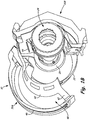
- FIG. 3A shows a perspective view of a section of pylon 12, interface feature 34, and one embodiment of forward mount 36.
- Forward mount 36 includes a platform 58, a wiffle tree assembly 60, a first and second A-arms 62A and 62B, ball joints 64A, 64B, 64C, 64D and 64E, pins 66A, 66B, 66C, 66D and 66E, case bosses 68A and 68B (only one shown in FIG. 3A ), and drag link 70.
- Forward mount 36 is attached directly to aircraft structure such as pylon 12 by an outer radial portion of platform 58.
- Inner radial portion of platform 58 has a linkage assembly and is connected to first and second A-arms 62A and 62B at opposing outer ends.
- First and second A-arms 62A and 62B are additionally connected to intermediate case 26 as well as whiffletree assembly 60.
- Whiffletree assembly 60 is connected to a rear central portion of platform 58.
- Whiffletree assembly 60 is connected to first A-arm 62A at a first end and to second A-arm 62B and at a second opposing end.
- First A-arm 62A and second A-arm 62B are connected to either side of intermediate case 26 while whiffletree assembly 60 and platform 58 are disposed generally above case 26 between first and second A-arms 62A and 62B.
- drag link 70 connects intermediate case 26 to platform 58.
- various additional components such as bushings and/or vibration isolators can additionally be utilized with forward mount 36.
- whiffletree assembly 60 has a central ball joint 64D extending therethrough. Central ball joint 64D receives pin 66D therein. Additionally, pin 66D extends into a forward portion of platform 58. As will be discussed in further detail subsequently, whiffletree assembly 60 allows engine thrust loads to be equalized and transmitted to pylon 12 through platform 58. This dual thrust link configuration is accomplished by central ball joint 64D and pin 66D, which allow whiffletree assembly 60 to rotate to equalize thrust forces in the axial direction relative to centerline axis C. A sliding linkage between whiffletree assembly 60 and first and second A arms 62A and 62B operates as an equalizing link for vertical loads.
- First A-arm 62A and second A-arm 62B are shown as a rigid single piece structure with a generally boomerang shape.
- Each A-arm 62A and 62B has a first ball joint 64A (only one is shown if FIG. 3A ) extending therethrough adjacent a first distal end thereof. First distal end is disposed adjacent intermediate case 26.
- first ball joints 64A extend through A-arm 62A and 62B and are positioned at substantially a 9 o'clock and 3 o'clock position relative to the centerline axis C (when viewing intermediate case 26 along centerline axis C).
- Pins 66A extend through first ball joints 64A and connect to case bosses 68A and 68B which are mounted on intermediate frame 26.
- pins 66 and case bosses 68 are positioned at substantially a 9 o'clock and 3 o'clock position relative to the centerline axis C allowing first and second A-arms 62A and 62B to react a thrust load at intermediate case 26 substantially parallel to the centerline axis C.
- ball joints 64A, pins 66A, and case bosses 68A can be disposed in a position other than the 9 o'clock and 3 o'clock position relative to the centerline axis C so as to react thrust in a vector that is not parallel to the centerline axis C.
- Each A-arm 62A and 62B has second ball joint 64B positioned at a rearward end thereof.
- second ball joints 64B receive pins 66B therethrough along a trailing edge of first and second A-arms 62A and 62B.
- Pins 66B additionally extend through first and second ends of whiffletree assembly 60.
- second ball joints 64B and pins 66B are constructed to permit sliding movement of the first and second A-arm 62A and 62B relative to whiffletree assembly 60 to allow a vertical load to be reacted by whiffletree assembly 60.
- Each A-arm 62A and 62B has third ball joint 64C (only one is shown in FIG. 3A ) positioned at a forward end thereof generally above first ball joint 64A relative to centerline axis C.
- Third ball joints 64C receive pins 66C therethrough. Pins 66C additionally extend into platform 58 at a forward portion thereof.
- Third ball joints 64C and pins 66C allow first A-arm 62A and the second A-arm 62B to support the vertical weight load of engine 10 and additionally transmit thrust loads from intermediate case 26 to the platform 58.
- Drag link 70 includes ball joint 64E and is mounted to intermediate case 26 by pin 66E. Although not shown in FIG. 3A , drag link 70 includes an additional ball joint and is mounted to the platform 58 by a pin (not shown). The drag link 70 operates to react torque loads at the intermediate case 26. Thus, in the manner described, forward mount 36 shown in FIG. 3A reacts thrust, vertical, side, and torque loads.
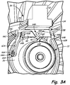
- FIG. 3B shows a perspective view of a section of pylon 12, interface feature 34, and another embodiment of forward mount 74.
- Forward mount 74 is similar to forward mount 36 ( FIG. 3A ) except that forward mount 74 does not include drag link 70. Therefore, forward mount 74 does not react a torque load. With the embodiment of mount shown in FIG. 3B , interface features 34 and 44 would not be necessary between doors 30 ( FIG. 3B ) and pylon 12.
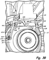
- FIG. 4A shows a rear view of a first embodiment of rear mount 38 from aft thereof.
- rear mount 38 is utilized in combination with forward mount 36 shown in FIG. 3A and includes a main body 76, tangential links 78A and 78B, ball joints 79A, 79AA, 79B, and 79BB, and pins 80A, 80AA, 80B, 80BB.
- Mid-turbine frame 28 includes flanges 82A and 82B.
- Main body 76 is mounted to a rear portion of pylon 12 along an outer radial portion and comprises a relatively thin plate like structure that extends generally radially therefrom toward centerline axis C.
- Main body 76 includes adapted linkage portions that connect to tangential links 78A and 78B.
- Tangential links 78A and 78B extend from main body 76 and connect to mid-turbine frame 28.
- tangential link 78A includes ball joints 79A and 79AA which receive pins 80A and 80AA to mount rear mount 38 to flange 82A.
- Ball joints 79A and 79AA and pins 80A and 80AA allow tangential link 78A to support the vertical weight load of engine 10 and react a side load at the mid-turbine frame 28.
- tangential link 78B includes ball joints 79B and 79BB which receive pins 80B and 80BB to mount rear mount 38 to flange 82B.
- Ball joints 79B and 79BB and pins 80B and 80BB allow tangential link 78B to support the vertical weight load of engine 10 and react a side load at the mid-turbine frame 28.
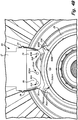
- FIG. 4B shows a second embodiment of rear mount 84.
- Rear mount 84 is utilized in combination with forward mount 74 of FIG. 3B and includes a main body 86, tangential link 88, boomerang link 90, ball joints 91A, 91AA, 91AAA, 91B, and 91BB, and pins 92A, 92AA, 92AAA, 92B, and 92BB.
- Mid-turbine frame 28 includes flanges 94A and 94B.
- Rear mount 84 has a design similar to that of rear mount 38 ( FIG. 4A ) but with the substitution of boomerang link 90, which allows the rear mount 84 to react torque load at mid-turbine frame 28 in addition to vertical loads and side loads.
- Main body 86 is connected to pylon 12.
- Main body 86 includes adapted linkage portions that connect to tangential link 88 and boomerang link 90. Tangential link 88 and boomerang link 90 extend from main body 86 and connect to mid-turbine frame 28.
- boomerang link 90 includes ball joints 91A, 91AA, and 91AAA which receive pins 92A, 92AA, and 92AAA to mount rear mount 84 to flange 94A.
- Ball joints 91A, 91AA, and 91AAA and pins 92A, 92AA, and 92AAA allow boomerang link 90 to support the vertical weight load of engine 10, react side loads, and react torque loads at the mid-turbine frame 28.
- Tangential link 88 includes ball joints 91B and 91BB which receive pins 92B and 92BB to mount rear mount 38 to flange 94B.
Description
- The present invention relates to a gas turbine engine and more particularly to an engine mount assembly for mounting a gas turbine engine to an aircraft pylon.
- Gas turbine engines are typically mounted at various points of an aircraft, such as a pylon that extends from the wing of the aircraft. A mount assembly is often used to support the gas turbine engine and connect the engine to the pylon. The mount assembly supports the engine vertically, laterally and axially and allows for the transmission of a variety of static and dynamic loads between the engine and the aircraft via the pylon.
- The loads experienced by the mount assembly and the gas turbine engine include vertical loads and side loads (i.e. loads experienced perpendicular to a centerline axis of the engine). An example of such loads occurs when the aircraft performs an end of the runway roll. This maneuver generates a moment in the cowl of the engine that is typically absorbed by narrow engine cases and the pylon. However, such an arrangement can lead to bending of the core (commonly called "backbone bending") of the engine, which reduces engine performance.
- Additional loads experienced by the mount assembly include torque loads (i.e. loads experienced in the direction of rotation of the gas turbine engine), and thrust loads (i.e. loads experienced in an opposing direction to aircraft travel). In addition to the loads that result from aircraft maneuvers, the mount assembly is subjected to static weight loads of the engine and to thermal expansion and retraction during operation.
- Typical mount assemblies for a gas turbine engine dissipate some loads including vertical loads and side loads at a forward mount located at the low pressure compressor (LPC) case at a front portion of the engine. Such mount assemblies also include a rear mount that dissipates vertical loads, side loads, torque loads, and thrust loads experienced adjacent a rear end of the engine.
- Unfortunately, mount assemblies of this type are unable to adequately react all loads created during operation of the engine. Thus, the casing surrounding various components distorts and flexes (i.e. is subject to backbone bending). This distortion can cause the clearances between the static casing and a plurality of rotating blade tips encased within the static casing to increase, negatively effecting engine performance.
- A mount assembly having some of the features of claim 1 is disclosed in
US 2009/314881 . - The present invention provides an engine mount assembly as recited in claim 1.
-
-
FIG. 1A is a schematic sectional view of a gas turbine engine including a pylon and an engine mount assembly. -
FIG. 1B is a semi-exploded perspective view of the gas turbine engine. -
FIG. 2 is an exploded perspective view of an axial linkage assembly between a fan case and a pylon superstructure. -
FIG. 3A is a perspective view of a section of the pylon showing one embodiment of a forward mount and interface feature. -
FIG. 3B is a perspective view of a section of pylon showing another embodiment of a forward mount and interface feature. -
FIG. 4A is a rear view of a section of pylon showing one embodiment of a rear mount and the interface feature. -
FIG. 4B is a rear view of a section of pylon showing another embodiment of a rear mount and the interface feature. -
FIG. 1A illustrates one embodiment of agas turbine engine 10 suspended from anengine pylon 12 connected to awing 14 of anaircraft 16.Engine pylon 12 is enclosed in a pylon superstructure 18 (which is illustrated in phantom in the view shown).Gas turbine engine 10 includes anacelle 20, afan case 22, acore 24, anintermediate case 26, and amid-turbine frame 28. Nacelle 20 includesdoors 30.Engine pylon 12 includes a mount assembly 32 and aninterface feature 34. Mount assembly 32 includes aforward mount 36 and arear mount 38. - The construction and operational characteristics of
gas turbine engine 10 are known, and therefore, will not be described in great detail. In the embodiment shown in the FIGURES,gas turbine engine 10 is a turbofan gas turbine engine but the invention is applicable to other types of gas turbine engines.Gas turbine engine 10 is connected towing 14 bypylon 12. Pylon 12 is enclosed bypylon superstructure 18 which is connected to nacelle 20 (and inparticular doors 30 of nacelle 20). Nacelle 20 enclosesfan case 22, which is disposed adjacent tocore 24. - In the embodiment shown in
FIG. 1A ,pylon 12 iscore 24 reaching andcore 24 mounted utilizing mount assembly 32. In particular,core 24 is a static structure generally comprised of several sub-structures and is often referred to as the engine backbone. One of such sub-structures isintermediate case 26 which is a stator structure that encloses portions of compressor section ofgas turbine engine 10. In the embodiment shown,intermediate case 26 encloses substantially the portion ofgas turbine engine 10 upstream of high pressure compressor section ofgas turbine engine 10. In other embodiments,intermediate case 26 can extend to include portions of the high pressure compressor. - Stator mid-turbine frame 28 (also called a thrust case) is disposed rearward of
intermediate case 26 and encloses hot sections ofcore 24 such as a combustor, a low pressure turbine section, and a high pressure turbine section. The number of hot sectionsmid-turbine frame 28 encompasses will vary from embodiment to embodiment. Further discussion of components ofcore 24 includingintermediate case 26 andmid-turbine frame 28 can be found in United States Patent Application Numbers2009/0056343 ,2009/0236469 , and2009/0314881 . - During operation, airflow is drawn into the
gas turbine engine 10 by the fan section. A portion of the airflow bypasses thecore 24 and passes through thenacelle 20 to exitgas turbine engine 10. A second portion of the airflow drawn by the fan section enters and is pressurized in the compressor sections (low and high). Fuel is mixed with the pressurized air and combusted within the combustor. The combustion gases are discharged through the turbine sections (high and low), which extract energy therefrom for powering the compressor sections and the fan section. - Aft portions of
nacelle 20 comprisedoors 30, which can be opened to exposecore 24 and other components ofgas turbine engine 10 for assembly and repair.Doors 20 are fastened or otherwise connected topylon superstructure 18. As shown inFIG. 1A ,gas turbine engine 10 is mounted toaircraft 16 structure such aswing 14 through mount assembly 32 attached topylon 12 at both forward and aft positions that compriseforward mount 36 andrear mount 38, respectively. In the embodiment shown inFIG. 1A ,interface feature 34 extends alongpylon 12 betweenforward mount 36 andrear mount 38 and interfaces and mates with a feature ondoors 30 to react torque loads. -
Pylon 12 extends along and interfaces withdoors 30. Additionally, the forward most extent ofpylon 12 extends to adjacentintermediate case 26 ofcore 24. Forward mount 36 is connected to pylon 12 at the forward most extend ofpylon 12. Additionally, forward mount 36 is connected tointermediate case 26. As will be discussed subsequently, the connections betweenforward mount 36 andintermediate case 26 can be made at or near 3 o'clock and 9 o'clock relative to a centerline axis C of gas turbine engine 10 (when viewed along centerline axis C). This allows forward mount 36 to react thrust loads (i.e. loads experienced in an opposing direction to aircraft travel) atintermediate case 26 substantially parallel to the centerline axis C ofgas turbine engine 10. In one embodiment, forward mount 36 additionally is capable of reacting a torque load (i.e. loads experienced in the direction of rotation of the gas turbine engine) at theintermediate case 26 as well as vertical and side loads (i.e. loads experienced perpendicular to a centerline axis of the engine). In yet another embodiment, forward mount 36 is capable of reacting only vertical and side loads in addition to thrust loads at theintermediate case 26. - Connecting forward mount 36 at or adjacent 3 o'clock and 9 o'clock relative to a centerline axis C of
gas turbine engine 10 to react thrust load substantially parallel to the centerline axis C ofgas turbine engine 10 reduces the likelihood of backbone bending ofcore 24 occurring during most operational maneuvers ofaircraft 16. - As used in this disclosure, "transmission of", "react", and "transfer" load means to absorb a load and dissipate the load to another location or structure of
gas turbine engine 10. Similarly, terms such as "front", "forward", "aft", "rear", "rearward" should be understood as positional terms in reference to the direction of airflow throughgas turbine engine 10. -
FIG. 1B shows a semi-exploded view ofgas turbine engine 10 includingfan case 22,core 24,intermediate case 26, anddoors doors inner diameter cowl 40, struts 42,interface feature 44, andouter diameter cowl 46.Inner diameter cowl 40 andouter diameter cowl 46 definebypass flow path 48.FIG. 1B is a perspective view from aft ofgas turbine engine 16 with pylon 12 (FIG. 1A ) and pylon superstructure 18 (FIG. 1A ) removed.Doors FIG. 1A ) and are connected to pylon superstructure 18 (FIG. 1 A) . -
FIG. 1B showsdoor 30A drawn back away fromcore 24.Intermediate case 26 is disposed at a forward portion ofcore 24. As previously discusseddoors FIG. 1A ), which can be can be opened to exposecore 24 and other components ofgas turbine engine 10 for assembly and repair. -
Doors core 24. In particular,inner diameter cowl 40 ofdoors core 24.Inner diameter cowl 40 comprises an inner diameter flow path forair bypassing core 24 alongbypass flow path 48. Similarly,outer diameter cowl 46 comprises an outer diameter flow path forair bypassing core 24 alongbypass flow path 48.Inner diameter cowl 40 is connected toouter diameter cowl 46 bystruts 42. - As shown in
FIG. 1B ,interface feature 44 can be disposed along a surface of onestrut 42 that abuts and engages pylon 12 (FIG. 1A ).Interface feature 44 extends alongdoors strut 42. Whendoors pylon 12,interface feature 44 mates with corresponding interface feature 34 (in one embodiment a groove) onpylon 12. In this manner, interface features 34 and 44 allow for transmission of torque loads frompylon 12 todoors -
FIG. 2 shows an exploded perspective view of anaxial linkage assembly 50 betweenfan case 22 and pylon superstructure 18 (shown in phantom).Axial linkage assembly 50 includesreceptacles axial member 54, and one or more pins 56. -
Axial linkage assembly 50 is disposed at an interface betweenfan case 22 andpylon superstructure 18. Thus,axial linkage assembly 50 extends through an aft portion offan case 22 intopylon superstructure 18. - As shown in
FIG. 2 ,receptacle 52A is formed infan case 22 along an aft portion thereof.Receptacle 52A is adapted to receiveaxial member 54.Axial member 54 is disposed generally axially with respect to the centerline axis A of gas turbine engine 10 (FIG. 1A ) and extends throughreceptacle 52A and is received inreceptacle 52B.Receptacle 52B is disposed inpylon superstructure 18.Axial member 54 is adapted with holes that receive one or more pins 56. Eachpin 56 extends throughreceptacle axial member 54.Pins 56 extend generally radially relative to the centerline axis C of thegas turbine engine 10. -
Pins 56 giveaxial linkage assembly 50, degrees of freedom in all direction but axial direction relative to centerline axis C. Thus,axial linkage assembly 50 does not react load in directions other than the axial direction. In this manner,axial linkage assembly 50 reduces or eliminates transmission of a moment generated on nacelle 20 (whenaircraft 16 performs certain maneuvers such as an end of the runway roll) topylon 12 andcore 24. By reducing or eliminating transmission of moment tocore 24, bending of the core 24 (backbone bending) can be reduced. Thus, performance ofgas turbine engine 10 can be better maintained. -
FIG. 3A shows a perspective view of a section ofpylon 12,interface feature 34, and one embodiment offorward mount 36. Forward mount 36 includes aplatform 58, awiffle tree assembly 60, a first andsecond A-arms case bosses 68A and 68B (only one shown inFIG. 3A ), anddrag link 70. - Forward mount 36 is attached directly to aircraft structure such as
pylon 12 by an outer radial portion ofplatform 58. Inner radial portion ofplatform 58 has a linkage assembly and is connected to first andsecond A-arms second A-arms intermediate case 26 as well aswhiffletree assembly 60.Whiffletree assembly 60 is connected to a rear central portion ofplatform 58.Whiffletree assembly 60 is connected to first A-arm 62A at a first end and tosecond A-arm 62B and at a second opposing end. First A-arm 62A and second A-arm 62B are connected to either side ofintermediate case 26 whilewhiffletree assembly 60 andplatform 58 are disposed generally abovecase 26 between first andsecond A-arms FIG. 3A ,drag link 70 connectsintermediate case 26 toplatform 58. Although not illustrated in the embodiment shown inFIG. 3A , various additional components such as bushings and/or vibration isolators can additionally be utilized withforward mount 36. - As shown,
whiffletree assembly 60 has a central ball joint 64D extending therethrough. Central ball joint 64D receivespin 66D therein. Additionally,pin 66D extends into a forward portion ofplatform 58. As will be discussed in further detail subsequently,whiffletree assembly 60 allows engine thrust loads to be equalized and transmitted to pylon 12 throughplatform 58. This dual thrust link configuration is accomplished by central ball joint 64D and pin 66D, which allowwhiffletree assembly 60 to rotate to equalize thrust forces in the axial direction relative to centerline axis C. A sliding linkage betweenwhiffletree assembly 60 and first andsecond A arms - First A-arm 62A and
second A-arm 62B are shown as a rigid single piece structure with a generally boomerang shape. Each A-arm 62A and 62B has a first ball joint 64A (only one is shown ifFIG. 3A ) extending therethrough adjacent a first distal end thereof. First distal end is disposed adjacentintermediate case 26. In one embodiment,first ball joints 64A extend throughA-arm intermediate case 26 along centerline axis C).Pins 66A extend throughfirst ball joints 64A and connect tocase bosses 68A and 68B which are mounted onintermediate frame 26. Thus, in the embodiment shown inFIG. 3A , pins 66 and case bosses 68 are positioned at substantially a 9 o'clock and 3 o'clock position relative to the centerline axis C allowing first andsecond A-arms intermediate case 26 substantially parallel to the centerline axis C. By resolving thrust load substantially parallel to the centerline axis C, backbone bending of core 24 (FIGS. 1A and1B ) during most operating conditions ofengine 10 can be reduced. In other embodiments, ball joints 64A, pins 66A, andcase bosses 68A can be disposed in a position other than the 9 o'clock and 3 o'clock position relative to the centerline axis C so as to react thrust in a vector that is not parallel to the centerline axis C. - Each A-arm 62A and 62B has second ball joint 64B positioned at a rearward end thereof. In the embodiment shown, second ball joints 64B receive
pins 66B therethrough along a trailing edge of first andsecond A-arms Pins 66B additionally extend through first and second ends ofwhiffletree assembly 60. In the embodiment shown, second ball joints 64B and pins 66B are constructed to permit sliding movement of the first andsecond A-arm whiffletree assembly 60 to allow a vertical load to be reacted bywhiffletree assembly 60. - Each A-arm 62A and 62B has third ball joint 64C (only one is shown in
FIG. 3A ) positioned at a forward end thereof generally above first ball joint 64A relative to centerline axis C. Third ball joints 64C receivepins 66C therethrough.Pins 66C additionally extend intoplatform 58 at a forward portion thereof.Third ball joints 64C and pins 66C allowfirst A-arm 62A and thesecond A-arm 62B to support the vertical weight load ofengine 10 and additionally transmit thrust loads fromintermediate case 26 to theplatform 58. -
Drag link 70 includes ball joint 64E and is mounted tointermediate case 26 bypin 66E. Although not shown inFIG. 3A ,drag link 70 includes an additional ball joint and is mounted to theplatform 58 by a pin (not shown). Thedrag link 70 operates to react torque loads at theintermediate case 26. Thus, in the manner described,forward mount 36 shown inFIG. 3A reacts thrust, vertical, side, and torque loads. -
FIG. 3B shows a perspective view of a section ofpylon 12,interface feature 34, and another embodiment offorward mount 74. Forward mount 74 is similar to forward mount 36 (FIG. 3A ) except that forward mount 74 does not includedrag link 70. Therefore, forward mount 74 does not react a torque load. With the embodiment of mount shown inFIG. 3B , interface features 34 and 44 would not be necessary between doors 30 (FIG. 3B ) andpylon 12. -
FIG. 4A shows a rear view of a first embodiment ofrear mount 38 from aft thereof. As will be explained subsequently,rear mount 38 is utilized in combination withforward mount 36 shown inFIG. 3A and includes amain body 76,tangential links Mid-turbine frame 28 includesflanges -
Main body 76 is mounted to a rear portion ofpylon 12 along an outer radial portion and comprises a relatively thin plate like structure that extends generally radially therefrom toward centerline axisC. Main body 76 includes adapted linkage portions that connect totangential links Tangential links main body 76 and connect tomid-turbine frame 28. In the embodiment shown,tangential link 78A includesball joints 79A and 79AA which receivepins 80A and 80AA to mountrear mount 38 toflange 82A.Ball joints 79A and 79AA and pins 80A and 80AA allowtangential link 78A to support the vertical weight load ofengine 10 and react a side load at themid-turbine frame 28. Similarly,tangential link 78B includes ball joints 79B and 79BB which receive pins 80B and 80BB to mountrear mount 38 toflange 82B. Ball joints 79B and 79BB and pins 80B and 80BB allowtangential link 78B to support the vertical weight load ofengine 10 and react a side load at themid-turbine frame 28. -
FIG. 4B shows a second embodiment ofrear mount 84. Rear mount 84 is utilized in combination withforward mount 74 ofFIG. 3B and includes amain body 86,tangential link 88,boomerang link 90, ball joints 91A, 91AA, 91AAA, 91B, and 91BB, and pins 92A, 92AA, 92AAA, 92B, and 92BB.Mid-turbine frame 28 includesflanges - Rear mount 84 has a design similar to that of rear mount 38 (
FIG. 4A ) but with the substitution ofboomerang link 90, which allows therear mount 84 to react torque load atmid-turbine frame 28 in addition to vertical loads and side loads.Main body 86 is connected topylon 12.Main body 86 includes adapted linkage portions that connect totangential link 88 andboomerang link 90.Tangential link 88 and boomerang link 90 extend frommain body 86 and connect tomid-turbine frame 28. In the embodiment shown,boomerang link 90 includes ball joints 91A, 91AA, and 91AAA which receive pins 92A, 92AA, and 92AAA to mountrear mount 84 toflange 94A. Ball joints 91A, 91AA, and 91AAA and pins 92A, 92AA, and 92AAA allowboomerang link 90 to support the vertical weight load ofengine 10, react side loads, and react torque loads at themid-turbine frame 28.Tangential link 88 includes ball joints 91B and 91BB which receivepins 92B and 92BB to mountrear mount 38 to flange 94B. - While the invention has been described with reference to an exemplary embodiment(s), it will be understood by those skilled in the art that various changes may be made and equivalents may be substituted for elements thereof without departing from the scope of the invention. In addition, many modifications may be made to adapt a particular situation or material to the teachings of the invention without departing from the essential scope thereof. Therefore, it is intended that the invention not be limited to the particular embodiment(s) disclosed, but that the invention will include all embodiments falling within the scope of the appended claims.
Claims (7)
- An engine mount assembly (36; 74) of a gas turbine engine (10), comprising:a pylon (12);an intermediate case (26) of a gas turbine engine (10);a forward mount platform (58) connected to the pylon (12) and disposed adjacent the intermediate case (26); a whiffletree assembly (60) connected to the forward mount platform (58) through a first balljoint; anda first A-arm (62A) connected to a first side of the intermediate case (26) and a second A-arm (62B) connected to a second opposing side of the intermediate case (26), wherein the first and second A-arms (62A, 62B) are mounted to the forward mount platform (58) and mounted to opposing ends of the whiffletree (60), and wherein the first and second A-arms (62A, 62B) react a thrust load at the intermediate case (26) substantially parallel to a centerline axis (C) of the gas turbine engine (10).
- The engine mount assembly (36; 74) of claim 1, wherein the first and second A-arms (62A, 62B) are mounted to the forward mount platform (58) and the whiffletree (60), and connected to the intermediate case (26) through a plurality of ball joints (64A).
- The engine mount assembly (36; 74) of claim 1 or 2, wherein the connection of the first A-arm (62A) with the intermediate case (26) and the connection of the second A-arm (62B) with the intermediate case (26) are disposed in a 3 o'clock position and a 9 o'clock position relative to the centerline axis (C) of the gas turbine engine (10) such that the first and second A-arms (62A, 62B) react the thrust load parallel to the centerline axis (C).
- The engine mount assembly (36) of any preceding claim, further comprising a drag link (70) connected to the intermediate case (26) and the forward mount platform (58), wherein the drag link (70) reacts a torque load at the intermediate case (26).
- The engine mount assembly (36; 74) of any preceding claim, further comprising one or more doors (30) connected to a pylon superstructure (18) surrounding a portion of the pylon (12), the one or more doors (30) having a first interface feature (44) that extends along a length thereof, wherein the pylon (12) includes a second interface feature (44) adapted to mate with the first interface feature (44) to react a torque load at the pylon (12).
- The engine mount assembly (36; 74) of any preceding claim, further comprising a rear mount assembly (38, 84) mounted to the pylon (12) and disposed at a distance along the gas turbine engine (10) from the forward mount assembly (36, 74), wherein the rear mount assembly (38, 84) is connected to a mid-turbine frame (28) of the gas turbine engine (10) by one or more tangential links (78A, 78B) so as to react a vertical load and a side load at the mid-turbine frame (28).
- The engine mount assembly (36; 74) of any of claims 1 to 5, further comprising a rear mount assembly (84) mounted to the pylon (12) and disposed at a distance along the gas turbine engine (10) from the forward mount assembly (74), wherein the rear mount assembly (84) is connected to a mid-turbine frame (28) of the gas turbine engine (10) by one or more tangential links (78A, 78B) and at least one boomerang link (90) so as to react a vertical load, a side load, and a torque load at the mid-turbine frame (28).
Applications Claiming Priority (1)
| Application Number | Priority Date | Filing Date | Title |
|---|---|---|---|
| US13/242,908 US20130074517A1 (en) | 2011-09-23 | 2011-09-23 | Gas turbine engine mount assembly |
Publications (3)
| Publication Number | Publication Date |
|---|---|
| EP2572986A2 EP2572986A2 (en) | 2013-03-27 |
| EP2572986A3 EP2572986A3 (en) | 2013-12-18 |
| EP2572986B1 true EP2572986B1 (en) | 2017-04-26 |
Family
ID=47008322
Family Applications (1)
| Application Number | Title | Priority Date | Filing Date |
|---|---|---|---|
| EP12185418.6A Active EP2572986B1 (en) | 2011-09-23 | 2012-09-21 | Gas turbine engine mount assembly |
Country Status (2)
| Country | Link |
|---|---|
| US (1) | US20130074517A1 (en) |
| EP (1) | EP2572986B1 (en) |
Families Citing this family (12)
| Publication number | Priority date | Publication date | Assignee | Title |
|---|---|---|---|---|
| FR3000467A1 (en) * | 2012-12-28 | 2014-07-04 | Airbus Operations Sas | THREE POINTS MANILA WITH VIBRATION FILTRATION CAPACITY AND AIRCRAFT ENGINE ATTACHMENT EQUIPPED WITH SUCH A MANILA |
| FR3040076B1 (en) * | 2015-08-13 | 2017-08-11 | Airbus Operations Sas | AIRCRAFT ENGINE ASSEMBLY COMPRISING A PRIMARY STRUCTURE OF A COUPLING MAT EQUIPPED WITH A BOX EXTENSION COMPRISING TWO PARTS IN GLOBAL ARCEAU SHAPE |
| FR3042010B1 (en) * | 2015-10-05 | 2018-07-13 | Safran Aircraft Engines | AIRCRAFT WITH A MULTI-BLOWING PROPULSIVE ASSEMBLY FIXED UNDER AILE |
| US10414509B2 (en) * | 2017-02-23 | 2019-09-17 | United Technologies Corporation | Propulsor mounting for advanced body aircraft |
| US10814993B2 (en) | 2017-08-21 | 2020-10-27 | Raytheon Technologies Corporation | Inlet cowl deflection limiting strut |
| FR3086924B1 (en) * | 2018-10-08 | 2021-02-12 | Safran Aircraft Engines | TURBOMACHINE WITH SUSPENSION MEANS |
| FR3090041B1 (en) | 2018-12-14 | 2020-11-27 | Safran Aircraft Engines | IMPROVED FIRE RESISTANCE DEVICE INTENDED TO BE INTERPOSED BETWEEN AN AIRCRAFT TURBOMACHINE HANGING MAST END, AND A TURBOMACHINE COWL DELIMING AN INTER-VEIN COMPARTMENT |
| US11420755B2 (en) * | 2019-08-08 | 2022-08-23 | General Electric Company | Shape memory alloy isolator for a gas turbine engine |
| US11697506B2 (en) * | 2020-05-15 | 2023-07-11 | General Electric Company | Methods and apparatus for gas turbine bending isolation |
| CN112572825B (en) * | 2020-11-27 | 2022-12-13 | 北京星航机电装备有限公司 | Aircraft tail cabin and assembly method thereof |
| GB202117777D0 (en) * | 2021-12-09 | 2022-01-26 | Rolls Royce Plc | Support structure for attaching a gas turbine engine to an aircraft pylon |
| US11884410B2 (en) | 2022-02-04 | 2024-01-30 | General Electric Company | Dual function links for gas turbine engine mounts |
Citations (1)
| Publication number | Priority date | Publication date | Assignee | Title |
|---|---|---|---|---|
| US20050194493A1 (en) * | 2004-03-04 | 2005-09-08 | Airbus France | Mounting system inserted between an aircraft engine and a rigid structure of an attachment strut fixed under a wing of this aircraft |
Family Cites Families (23)
| Publication number | Priority date | Publication date | Assignee | Title |
|---|---|---|---|---|
| DE69012071T2 (en) * | 1989-12-05 | 1995-04-13 | Rolls Royce Plc | Fail-safe holding device for engines. |
| FR2680353B1 (en) * | 1991-08-14 | 1993-10-15 | Snecma | REAR HANGING STRUCTURE OF A TURBOREACTOR. |
| US5860623A (en) * | 1995-05-03 | 1999-01-19 | The Boeing Company | Three link failsafe engine mount |
| FR2774358B1 (en) * | 1998-02-04 | 2000-04-21 | Aerospatiale | HANGING DEVICE OF AN AIRCRAFT ENGINE |
| US6189830B1 (en) * | 1999-02-26 | 2001-02-20 | The Boeing Company | Tuned engine mounting system for jet aircraft |
| GB9927425D0 (en) * | 1999-11-20 | 2000-01-19 | Rolls Royce Plc | A gas turbine engine mounting arrangement |
| US6330995B1 (en) * | 2000-02-29 | 2001-12-18 | General Electric Company | Aircraft engine mount |
| US6296203B1 (en) * | 2000-05-24 | 2001-10-02 | General Electric Company | Snubber thrust mount |
| US6401448B1 (en) * | 2000-08-31 | 2002-06-11 | General Electric Company | System for mounting aircraft engines |
| FR2818614B1 (en) * | 2000-12-21 | 2003-01-31 | Snecma Moteurs | SUSPENSION PART OF A TURBO-JET |
| FR2820402B1 (en) * | 2001-02-08 | 2003-05-02 | Eads Airbus Sa | DEVICE FOR HANGING AN ENGINE ON AN AIRCRAFT |
| FR2855496B1 (en) * | 2003-05-27 | 2006-09-22 | Snecma Moteurs | REAR SUSPENSION OF AIRCRAFT ENGINE WITH PUSH REPEAT |
| FR2855495B1 (en) * | 2003-05-27 | 2006-11-24 | Snecma Moteurs | DEVICE FOR FRONT ATTACHMENT OF AIRCRAFT ENGINE |
| FR2856656B1 (en) * | 2003-06-30 | 2006-12-01 | Snecma Moteurs | AIRCRAFT ENGINE REAR SUSPENSION WITH BOOMERANG SHAFT AND BOOMERANG SHAFT |
| US6843449B1 (en) * | 2004-02-09 | 2005-01-18 | General Electric Company | Fail-safe aircraft engine mounting system |
| FR2891253B1 (en) * | 2005-09-28 | 2007-10-26 | Airbus France Sas | REAR ATTACHMENT OF A TWO-SHOWN AIRCRAFT ENGINE |
| FR2915176B1 (en) * | 2007-04-20 | 2009-07-10 | Airbus France Sa | ENGINE ATTACHING MACHINE FOR AN AIRCRAFT HAVING A REAR ENGINE ATTACHMENT HAVING A BARREL NUT |
| US8256707B2 (en) | 2007-08-01 | 2012-09-04 | United Technologies Corporation | Engine mounting configuration for a turbofan gas turbine engine |
| US8167237B2 (en) * | 2008-03-21 | 2012-05-01 | United Technologies Corporation | Mounting system for a gas turbine engine |
| US8128021B2 (en) | 2008-06-02 | 2012-03-06 | United Technologies Corporation | Engine mount system for a turbofan gas turbine engine |
| US8713910B2 (en) * | 2009-07-31 | 2014-05-06 | General Electric Company | Integrated thrust reverser/pylon assembly |
| JP5642379B2 (en) * | 2009-12-01 | 2014-12-17 | 三菱航空機株式会社 | Aircraft engine mount, aircraft |
| US8672260B2 (en) * | 2009-12-02 | 2014-03-18 | United Technologies Corporation | Single plane mount system for gas turbine engine |
-
2011
- 2011-09-23 US US13/242,908 patent/US20130074517A1/en not_active Abandoned
-
2012
- 2012-09-21 EP EP12185418.6A patent/EP2572986B1/en active Active
Patent Citations (1)
| Publication number | Priority date | Publication date | Assignee | Title |
|---|---|---|---|---|
| US20050194493A1 (en) * | 2004-03-04 | 2005-09-08 | Airbus France | Mounting system inserted between an aircraft engine and a rigid structure of an attachment strut fixed under a wing of this aircraft |
Also Published As
| Publication number | Publication date |
|---|---|
| EP2572986A2 (en) | 2013-03-27 |
| US20130074517A1 (en) | 2013-03-28 |
| EP2572986A3 (en) | 2013-12-18 |
Similar Documents
| Publication | Publication Date | Title |
|---|---|---|
| EP2572986B1 (en) | Gas turbine engine mount assembly | |
| US8118251B2 (en) | Mounting system for a gas turbine engine | |
| US8128021B2 (en) | Engine mount system for a turbofan gas turbine engine | |
| EP2103516B1 (en) | Mounting system for a gas turbine engine | |
| US4603821A (en) | System for mounting a jet engine | |
| US6976655B2 (en) | Mounting arrangement | |
| US8844861B2 (en) | Aircraft propulsion system | |
| JP4498694B2 (en) | Aircraft engine mount with a single thrust link | |
| EP2718185B1 (en) | System and method for mounting an aircraft engine | |
| US8733693B2 (en) | Aircraft engine assembly comprising an annular load-transfer structure surrounding the central casing of a turbojet engine | |
| EP3273010A1 (en) | Mid-turbine frame | |
| EP2441673B1 (en) | Support structure | |
| US11542022B2 (en) | Aircraft propulsion assembly | |
| CN109562841B (en) | Mounting system, device and method for aircraft engine | |
| US20080272230A1 (en) | Engine Assembly for Aircraft | |
| US8881536B2 (en) | Aircraft engine assembly comprising a turbojet engine with reinforcing structures connecting the fan casing to the central casing | |
| CN112805219B (en) | Turbomachine including a suspension member | |
| US20210300577A1 (en) | Engine backbone bending reduction | |
| US11970280B2 (en) | Assembly between an aircraft pylon and a turbomachine | |
| US20220119123A1 (en) | Propulsion engine and cowl | |
| CN114379793A (en) | Damper engine mounting connecting rod | |
| CN113669115A (en) | Method and apparatus for gas turbine bend isolation |
Legal Events
| Date | Code | Title | Description |
|---|---|---|---|
| PUAI | Public reference made under article 153(3) epc to a published international application that has entered the european phase |
Free format text: ORIGINAL CODE: 0009012 |
|
| AK | Designated contracting states |
Kind code of ref document: A2 Designated state(s): AL AT BE BG CH CY CZ DE DK EE ES FI FR GB GR HR HU IE IS IT LI LT LU LV MC MK MT NL NO PL PT RO RS SE SI SK SM TR |
|
| AX | Request for extension of the european patent |
Extension state: BA ME |
|
| PUAL | Search report despatched |
Free format text: ORIGINAL CODE: 0009013 |
|
| AK | Designated contracting states |
Kind code of ref document: A3 Designated state(s): AL AT BE BG CH CY CZ DE DK EE ES FI FR GB GR HR HU IE IS IT LI LT LU LV MC MK MT NL NO PL PT RO RS SE SI SK SM TR |
|
| AX | Request for extension of the european patent |
Extension state: BA ME |
|
| RIC1 | Information provided on ipc code assigned before grant |
Ipc: B64D 27/12 20060101ALI20131111BHEP Ipc: B64D 27/18 20060101ALI20131111BHEP Ipc: B64D 27/26 20060101AFI20131111BHEP |
|
| 17P | Request for examination filed |
Effective date: 20140606 |
|
| RBV | Designated contracting states (corrected) |
Designated state(s): AL AT BE BG CH CY CZ DE DK EE ES FI FR GB GR HR HU IE IS IT LI LT LU LV MC MK MT NL NO PL PT RO RS SE SI SK SM TR |
|
| REG | Reference to a national code |
Ref country code: DE Ref legal event code: R079 Ref document number: 602012031556 Country of ref document: DE Free format text: PREVIOUS MAIN CLASS: B64D0027180000 Ipc: B64D0027260000 |
|
| RIC1 | Information provided on ipc code assigned before grant |
Ipc: B64D 27/12 20060101ALI20140905BHEP Ipc: B64D 27/26 20060101AFI20140905BHEP Ipc: B64D 27/18 20060101ALI20140905BHEP |
|
| 17Q | First examination report despatched |
Effective date: 20141104 |
|
| GRAP | Despatch of communication of intention to grant a patent |
Free format text: ORIGINAL CODE: EPIDOSNIGR1 |
|
| RAP1 | Party data changed (applicant data changed or rights of an application transferred) |
Owner name: UNITED TECHNOLOGIES CORPORATION |
|
| INTG | Intention to grant announced |
Effective date: 20161017 |
|
| RIN1 | Information on inventor provided before grant (corrected) |
Inventor name: SUCIU, GABRIEL L. Inventor name: MERRY, BRIAN D. Inventor name: DYE, CHRISTOPHER M. |
|
| GRAS | Grant fee paid |
Free format text: ORIGINAL CODE: EPIDOSNIGR3 |
|
| GRAJ | Information related to disapproval of communication of intention to grant by the applicant or resumption of examination proceedings by the epo deleted |
Free format text: ORIGINAL CODE: EPIDOSDIGR1 |
|
| GRAL | Information related to payment of fee for publishing/printing deleted |
Free format text: ORIGINAL CODE: EPIDOSDIGR3 |
|
| GRAR | Information related to intention to grant a patent recorded |
Free format text: ORIGINAL CODE: EPIDOSNIGR71 |
|
| GRAA | (expected) grant |
Free format text: ORIGINAL CODE: 0009210 |
|
| INTC | Intention to grant announced (deleted) | ||
| AK | Designated contracting states |
Kind code of ref document: B1 Designated state(s): AL AT BE BG CH CY CZ DE DK EE ES FI FR GB GR HR HU IE IS IT LI LT LU LV MC MK MT NL NO PL PT RO RS SE SI SK SM TR |
|
| INTG | Intention to grant announced |
Effective date: 20170320 |
|
| REG | Reference to a national code |
Ref country code: GB Ref legal event code: FG4D |
|
| REG | Reference to a national code |
Ref country code: CH Ref legal event code: EP |
|
| REG | Reference to a national code |
Ref country code: AT Ref legal event code: REF Ref document number: 887641 Country of ref document: AT Kind code of ref document: T Effective date: 20170515 |
|
| REG | Reference to a national code |
Ref country code: IE Ref legal event code: FG4D |
|
| REG | Reference to a national code |
Ref country code: DE Ref legal event code: R096 Ref document number: 602012031556 Country of ref document: DE |
|
| REG | Reference to a national code |
Ref country code: DE Ref legal event code: R082 Ref document number: 602012031556 Country of ref document: DE Representative=s name: SCHMITT-NILSON SCHRAUD WAIBEL WOHLFROM PATENTA, DE |
|
| REG | Reference to a national code |
Ref country code: FR Ref legal event code: PLFP Year of fee payment: 6 |
|
| REG | Reference to a national code |
Ref country code: NL Ref legal event code: MP Effective date: 20170426 |
|
| REG | Reference to a national code |
Ref country code: LT Ref legal event code: MG4D |
|
| REG | Reference to a national code |
Ref country code: AT Ref legal event code: MK05 Ref document number: 887641 Country of ref document: AT Kind code of ref document: T Effective date: 20170426 |
|
| PG25 | Lapsed in a contracting state [announced via postgrant information from national office to epo] |
Ref country code: NL Free format text: LAPSE BECAUSE OF FAILURE TO SUBMIT A TRANSLATION OF THE DESCRIPTION OR TO PAY THE FEE WITHIN THE PRESCRIBED TIME-LIMIT Effective date: 20170426 |
|
| PG25 | Lapsed in a contracting state [announced via postgrant information from national office to epo] |
Ref country code: ES Free format text: LAPSE BECAUSE OF FAILURE TO SUBMIT A TRANSLATION OF THE DESCRIPTION OR TO PAY THE FEE WITHIN THE PRESCRIBED TIME-LIMIT Effective date: 20170426 Ref country code: GR Free format text: LAPSE BECAUSE OF FAILURE TO SUBMIT A TRANSLATION OF THE DESCRIPTION OR TO PAY THE FEE WITHIN THE PRESCRIBED TIME-LIMIT Effective date: 20170727 Ref country code: HR Free format text: LAPSE BECAUSE OF FAILURE TO SUBMIT A TRANSLATION OF THE DESCRIPTION OR TO PAY THE FEE WITHIN THE PRESCRIBED TIME-LIMIT Effective date: 20170426 Ref country code: AT Free format text: LAPSE BECAUSE OF FAILURE TO SUBMIT A TRANSLATION OF THE DESCRIPTION OR TO PAY THE FEE WITHIN THE PRESCRIBED TIME-LIMIT Effective date: 20170426 Ref country code: LT Free format text: LAPSE BECAUSE OF FAILURE TO SUBMIT A TRANSLATION OF THE DESCRIPTION OR TO PAY THE FEE WITHIN THE PRESCRIBED TIME-LIMIT Effective date: 20170426 Ref country code: NO Free format text: LAPSE BECAUSE OF FAILURE TO SUBMIT A TRANSLATION OF THE DESCRIPTION OR TO PAY THE FEE WITHIN THE PRESCRIBED TIME-LIMIT Effective date: 20170726 Ref country code: FI Free format text: LAPSE BECAUSE OF FAILURE TO SUBMIT A TRANSLATION OF THE DESCRIPTION OR TO PAY THE FEE WITHIN THE PRESCRIBED TIME-LIMIT Effective date: 20170426 |
|
| PG25 | Lapsed in a contracting state [announced via postgrant information from national office to epo] |
Ref country code: RS Free format text: LAPSE BECAUSE OF FAILURE TO SUBMIT A TRANSLATION OF THE DESCRIPTION OR TO PAY THE FEE WITHIN THE PRESCRIBED TIME-LIMIT Effective date: 20170426 Ref country code: IS Free format text: LAPSE BECAUSE OF FAILURE TO SUBMIT A TRANSLATION OF THE DESCRIPTION OR TO PAY THE FEE WITHIN THE PRESCRIBED TIME-LIMIT Effective date: 20170826 Ref country code: BG Free format text: LAPSE BECAUSE OF FAILURE TO SUBMIT A TRANSLATION OF THE DESCRIPTION OR TO PAY THE FEE WITHIN THE PRESCRIBED TIME-LIMIT Effective date: 20170726 Ref country code: PL Free format text: LAPSE BECAUSE OF FAILURE TO SUBMIT A TRANSLATION OF THE DESCRIPTION OR TO PAY THE FEE WITHIN THE PRESCRIBED TIME-LIMIT Effective date: 20170426 Ref country code: SE Free format text: LAPSE BECAUSE OF FAILURE TO SUBMIT A TRANSLATION OF THE DESCRIPTION OR TO PAY THE FEE WITHIN THE PRESCRIBED TIME-LIMIT Effective date: 20170426 Ref country code: LV Free format text: LAPSE BECAUSE OF FAILURE TO SUBMIT A TRANSLATION OF THE DESCRIPTION OR TO PAY THE FEE WITHIN THE PRESCRIBED TIME-LIMIT Effective date: 20170426 |
|
| REG | Reference to a national code |
Ref country code: DE Ref legal event code: R097 Ref document number: 602012031556 Country of ref document: DE |
|
| PG25 | Lapsed in a contracting state [announced via postgrant information from national office to epo] |
Ref country code: EE Free format text: LAPSE BECAUSE OF FAILURE TO SUBMIT A TRANSLATION OF THE DESCRIPTION OR TO PAY THE FEE WITHIN THE PRESCRIBED TIME-LIMIT Effective date: 20170426 Ref country code: DK Free format text: LAPSE BECAUSE OF FAILURE TO SUBMIT A TRANSLATION OF THE DESCRIPTION OR TO PAY THE FEE WITHIN THE PRESCRIBED TIME-LIMIT Effective date: 20170426 Ref country code: SK Free format text: LAPSE BECAUSE OF FAILURE TO SUBMIT A TRANSLATION OF THE DESCRIPTION OR TO PAY THE FEE WITHIN THE PRESCRIBED TIME-LIMIT Effective date: 20170426 Ref country code: RO Free format text: LAPSE BECAUSE OF FAILURE TO SUBMIT A TRANSLATION OF THE DESCRIPTION OR TO PAY THE FEE WITHIN THE PRESCRIBED TIME-LIMIT Effective date: 20170426 Ref country code: CZ Free format text: LAPSE BECAUSE OF FAILURE TO SUBMIT A TRANSLATION OF THE DESCRIPTION OR TO PAY THE FEE WITHIN THE PRESCRIBED TIME-LIMIT Effective date: 20170426 |
|
| PG25 | Lapsed in a contracting state [announced via postgrant information from national office to epo] |
Ref country code: IT Free format text: LAPSE BECAUSE OF FAILURE TO SUBMIT A TRANSLATION OF THE DESCRIPTION OR TO PAY THE FEE WITHIN THE PRESCRIBED TIME-LIMIT Effective date: 20170426 Ref country code: SM Free format text: LAPSE BECAUSE OF FAILURE TO SUBMIT A TRANSLATION OF THE DESCRIPTION OR TO PAY THE FEE WITHIN THE PRESCRIBED TIME-LIMIT Effective date: 20170426 |
|
| PLBE | No opposition filed within time limit |
Free format text: ORIGINAL CODE: 0009261 |
|
| STAA | Information on the status of an ep patent application or granted ep patent |
Free format text: STATUS: NO OPPOSITION FILED WITHIN TIME LIMIT |
|
| 26N | No opposition filed |
Effective date: 20180129 |
|
| REG | Reference to a national code |
Ref country code: CH Ref legal event code: PL |
|
| PG25 | Lapsed in a contracting state [announced via postgrant information from national office to epo] |
Ref country code: MC Free format text: LAPSE BECAUSE OF FAILURE TO SUBMIT A TRANSLATION OF THE DESCRIPTION OR TO PAY THE FEE WITHIN THE PRESCRIBED TIME-LIMIT Effective date: 20170426 Ref country code: SI Free format text: LAPSE BECAUSE OF FAILURE TO SUBMIT A TRANSLATION OF THE DESCRIPTION OR TO PAY THE FEE WITHIN THE PRESCRIBED TIME-LIMIT Effective date: 20170426 |
|
| REG | Reference to a national code |
Ref country code: IE Ref legal event code: MM4A |
|
| REG | Reference to a national code |
Ref country code: BE Ref legal event code: MM Effective date: 20170930 |
|
| PG25 | Lapsed in a contracting state [announced via postgrant information from national office to epo] |
Ref country code: LU Free format text: LAPSE BECAUSE OF NON-PAYMENT OF DUE FEES Effective date: 20170921 |
|
| PG25 | Lapsed in a contracting state [announced via postgrant information from national office to epo] |
Ref country code: CH Free format text: LAPSE BECAUSE OF NON-PAYMENT OF DUE FEES Effective date: 20170930 Ref country code: IE Free format text: LAPSE BECAUSE OF NON-PAYMENT OF DUE FEES Effective date: 20170921 Ref country code: LI Free format text: LAPSE BECAUSE OF NON-PAYMENT OF DUE FEES Effective date: 20170930 |
|
| REG | Reference to a national code |
Ref country code: FR Ref legal event code: PLFP Year of fee payment: 7 |
|
| PG25 | Lapsed in a contracting state [announced via postgrant information from national office to epo] |
Ref country code: BE Free format text: LAPSE BECAUSE OF NON-PAYMENT OF DUE FEES Effective date: 20170930 |
|
| PG25 | Lapsed in a contracting state [announced via postgrant information from national office to epo] |
Ref country code: MT Free format text: LAPSE BECAUSE OF NON-PAYMENT OF DUE FEES Effective date: 20170921 |
|
| PG25 | Lapsed in a contracting state [announced via postgrant information from national office to epo] |
Ref country code: HU Free format text: LAPSE BECAUSE OF FAILURE TO SUBMIT A TRANSLATION OF THE DESCRIPTION OR TO PAY THE FEE WITHIN THE PRESCRIBED TIME-LIMIT; INVALID AB INITIO Effective date: 20120921 |
|
| PG25 | Lapsed in a contracting state [announced via postgrant information from national office to epo] |
Ref country code: CY Free format text: LAPSE BECAUSE OF NON-PAYMENT OF DUE FEES Effective date: 20170426 |
|
| PG25 | Lapsed in a contracting state [announced via postgrant information from national office to epo] |
Ref country code: MK Free format text: LAPSE BECAUSE OF FAILURE TO SUBMIT A TRANSLATION OF THE DESCRIPTION OR TO PAY THE FEE WITHIN THE PRESCRIBED TIME-LIMIT Effective date: 20170426 |
|
| PG25 | Lapsed in a contracting state [announced via postgrant information from national office to epo] |
Ref country code: TR Free format text: LAPSE BECAUSE OF FAILURE TO SUBMIT A TRANSLATION OF THE DESCRIPTION OR TO PAY THE FEE WITHIN THE PRESCRIBED TIME-LIMIT Effective date: 20170426 |
|
| PG25 | Lapsed in a contracting state [announced via postgrant information from national office to epo] |
Ref country code: PT Free format text: LAPSE BECAUSE OF FAILURE TO SUBMIT A TRANSLATION OF THE DESCRIPTION OR TO PAY THE FEE WITHIN THE PRESCRIBED TIME-LIMIT Effective date: 20170426 |
|
| PG25 | Lapsed in a contracting state [announced via postgrant information from national office to epo] |
Ref country code: AL Free format text: LAPSE BECAUSE OF FAILURE TO SUBMIT A TRANSLATION OF THE DESCRIPTION OR TO PAY THE FEE WITHIN THE PRESCRIBED TIME-LIMIT Effective date: 20170426 |
|
| REG | Reference to a national code |
Ref country code: DE Ref legal event code: R081 Ref document number: 602012031556 Country of ref document: DE Owner name: RAYTHEON TECHNOLOGIES CORPORATION (N.D.GES.D.S, US Free format text: FORMER OWNER: UNITED TECHNOLOGIES CORPORATION, FARMINGTON, CONN., US |
|
| P01 | Opt-out of the competence of the unified patent court (upc) registered |
Effective date: 20230520 |
|
| PGFP | Annual fee paid to national office [announced via postgrant information from national office to epo] |
Ref country code: GB Payment date: 20230823 Year of fee payment: 12 |
|
| REG | Reference to a national code |
Ref country code: DE Ref legal event code: R079 Ref document number: 602012031556 Country of ref document: DE Free format text: PREVIOUS MAIN CLASS: B64D0027260000 Ipc: B64D0027400000 |
|
| PGFP | Annual fee paid to national office [announced via postgrant information from national office to epo] |
Ref country code: FR Payment date: 20230822 Year of fee payment: 12 Ref country code: DE Payment date: 20230822 Year of fee payment: 12 |