EP2080730A1 - Self-propelled industrial vehicle - Google Patents
Self-propelled industrial vehicle Download PDFInfo
- Publication number
- EP2080730A1 EP2080730A1 EP08167550A EP08167550A EP2080730A1 EP 2080730 A1 EP2080730 A1 EP 2080730A1 EP 08167550 A EP08167550 A EP 08167550A EP 08167550 A EP08167550 A EP 08167550A EP 2080730 A1 EP2080730 A1 EP 2080730A1
- Authority
- EP
- European Patent Office
- Prior art keywords
- self
- support plate
- propelled vehicle
- chassis
- propelled
- Prior art date
- Legal status (The legal status is an assumption and is not a legal conclusion. Google has not performed a legal analysis and makes no representation as to the accuracy of the status listed.)
- Withdrawn
Links
Images


Classifications
-
- E—FIXED CONSTRUCTIONS
- E02—HYDRAULIC ENGINEERING; FOUNDATIONS; SOIL SHIFTING
- E02F—DREDGING; SOIL-SHIFTING
- E02F3/00—Dredgers; Soil-shifting machines
- E02F3/04—Dredgers; Soil-shifting machines mechanically-driven
- E02F3/28—Dredgers; Soil-shifting machines mechanically-driven with digging tools mounted on a dipper- or bucket-arm, i.e. there is either one arm or a pair of arms, e.g. dippers, buckets
- E02F3/283—Dredgers; Soil-shifting machines mechanically-driven with digging tools mounted on a dipper- or bucket-arm, i.e. there is either one arm or a pair of arms, e.g. dippers, buckets with a single arm pivoted directly on the chassis
- E02F3/286—Dredgers; Soil-shifting machines mechanically-driven with digging tools mounted on a dipper- or bucket-arm, i.e. there is either one arm or a pair of arms, e.g. dippers, buckets with a single arm pivoted directly on the chassis telescopic or slidable
-
- B—PERFORMING OPERATIONS; TRANSPORTING
- B66—HOISTING; LIFTING; HAULING
- B66F—HOISTING, LIFTING, HAULING OR PUSHING, NOT OTHERWISE PROVIDED FOR, e.g. DEVICES WHICH APPLY A LIFTING OR PUSHING FORCE DIRECTLY TO THE SURFACE OF A LOAD
- B66F11/00—Lifting devices specially adapted for particular uses not otherwise provided for
- B66F11/04—Lifting devices specially adapted for particular uses not otherwise provided for for movable platforms or cabins, e.g. on vehicles, permitting workmen to place themselves in any desired position for carrying out required operations
- B66F11/044—Working platforms suspended from booms
- B66F11/046—Working platforms suspended from booms of the telescoping type
-
- B—PERFORMING OPERATIONS; TRANSPORTING
- B66—HOISTING; LIFTING; HAULING
- B66F—HOISTING, LIFTING, HAULING OR PUSHING, NOT OTHERWISE PROVIDED FOR, e.g. DEVICES WHICH APPLY A LIFTING OR PUSHING FORCE DIRECTLY TO THE SURFACE OF A LOAD
- B66F9/00—Devices for lifting or lowering bulky or heavy goods for loading or unloading purposes
- B66F9/06—Devices for lifting or lowering bulky or heavy goods for loading or unloading purposes movable, with their loads, on wheels or the like, e.g. fork-lift trucks
- B66F9/065—Devices for lifting or lowering bulky or heavy goods for loading or unloading purposes movable, with their loads, on wheels or the like, e.g. fork-lift trucks non-masted
- B66F9/0655—Devices for lifting or lowering bulky or heavy goods for loading or unloading purposes movable, with their loads, on wheels or the like, e.g. fork-lift trucks non-masted with a telescopic boom
-
- E—FIXED CONSTRUCTIONS
- E02—HYDRAULIC ENGINEERING; FOUNDATIONS; SOIL SHIFTING
- E02F—DREDGING; SOIL-SHIFTING
- E02F3/00—Dredgers; Soil-shifting machines
- E02F3/04—Dredgers; Soil-shifting machines mechanically-driven
- E02F3/28—Dredgers; Soil-shifting machines mechanically-driven with digging tools mounted on a dipper- or bucket-arm, i.e. there is either one arm or a pair of arms, e.g. dippers, buckets
- E02F3/34—Dredgers; Soil-shifting machines mechanically-driven with digging tools mounted on a dipper- or bucket-arm, i.e. there is either one arm or a pair of arms, e.g. dippers, buckets with bucket-arms, i.e. a pair of arms, e.g. manufacturing processes, form, geometry, material of bucket-arms directly pivoted on the frames of tractors or self-propelled machines
- E02F3/348—Buckets emptying into a collecting or conveying device
- E02F3/3486—Buckets discharging overhead into a container mounted on the machine
-
- E—FIXED CONSTRUCTIONS
- E02—HYDRAULIC ENGINEERING; FOUNDATIONS; SOIL SHIFTING
- E02F—DREDGING; SOIL-SHIFTING
- E02F9/00—Component parts of dredgers or soil-shifting machines, not restricted to one of the kinds covered by groups E02F3/00 - E02F7/00
- E02F9/08—Superstructures; Supports for superstructures
- E02F9/10—Supports for movable superstructures mounted on travelling or walking gears or on other superstructures
- E02F9/12—Slewing or traversing gears
- E02F9/121—Turntables, i.e. structure rotatable about 360°
Definitions
- the present invention is related to an industrial vehicle, of the self-propelled type, provided with tools useful for carrying out the operation foreseen for it.
- Examples of industrial vehicle falling within this definition are, for instance, a dumper provided with a mechanical bucket and a hopper, a fork lifter, an excavator, an articulated crane, a lifting platform and so on.
- vehicles as depicted above are known, usually comprising a self-propelled chassis, e.g. crawler-mounted, and various kind of tools mounted above the chassis.
- a self-propelled chassis e.g. crawler-mounted
- various kind of tools mounted above the chassis.
- a self-loading dumper as previously defined is provided with a loading bucket, mounted on articulated arms, and a hopper, and the main feature thereof is its capacity to move an load the hopper with its own bucket.
- the limit in the use of the self loading dumper lies in its capacity of loading only in an area localized in front of the hopper according to the direction of travel. Therefore, for loading material which is not placed just on its track, the dumper is forced to move itself, to be placed in a loading position, through even complicated maneuvering, possibly on a rough and slope grounds.
- lifters With reference to lifters, they are generally provided with forks, hooks, blades apt to work in front of the vehicle, which has the capacity to rotate as a whole and to follow a curved track.
- Such a configuration allows an eased use in storing areas and depots, where the loads are arranged in an ordered manner, with corridors and spaces allowing the lifter to move so as to place itself with said loads in a frontal position for the lifting thereof.
- the technical problems underlying the present invention is to provide a self-propelled vehicle allowing to obviate to the drawbacks mentioned with reference to the prior art.
- a self-propelled vehicle as above specified, comprising:
- the main advantage of the self-propelled vehicle according to the present invention lies in allowing the rotation of the whole rotating plate which can support the operative tools, separating such a rotation from the whole vehicle.
- a self-loading dumper shown with the reference number 1, will be described in the following, as an example of self-propelled vehicle according to the invention.
- Crawlers 2 support a self-propelled chassis 8, onto which the cab 6 is provided, and comprising a motor and all the controls of hopper and bucket.
- the chassis 8 Frontally, opposite the cab 6, the chassis 8 supports a support plate 9 entirely resting above the chassis 8.
- the plate 9 is horizontally disposed and it is constrained to the cab 6.
- the dumper 1 comprises drive means, placed between the chassis 8 and the support plate 9, apt to rotate the support plate 9.
- said drive means comprises a fifth wheel 10 fixed to the plate 9 by means of crown-disposed bolts.
- the fifth wheel 10 is rotated by means of a motor-driven pinion gear 11.
- the plate 9 receives said hopper 3, and the respective controls thereon, so that the hopper 3 can be rotated relative to chassis 8 and crawlers, opposite to the operator.
- the plate 9 is provided with supporting projections 12 at the side edges thereof, supporting the articulated arms 5 and the controls thereof, respectively. Accordingly, arms 5 and loading bucket 4 can rotate together with the hopper 3, thus always remaining in an optimal position for the material loading.
- the arms 5 are optimally placed for being controlled in a position in which they provide the dumper a balanced configuration, even when the hopper 3 is rotated.
- the fifth wheel 10 rotation axis A is substantially centered on the plate 9, in a vertical position.
- Crawlers 2 support a self-propelled chassis 8, onto which the cab 6 is provided, and comprising a motor and all the controls of device for grasping, lifting, and/or moving loads 3A, provided on the chassis 8 opposite the cab 6.
- Such device 3A comprises a telescopically extensible arm 5, formed by two parts 5a and 5b, articulated at the base to a support plate 9 in correspondence of a hinge structure 5c.
- the arm 5 On its distal end, the arm 5 has a pair of forks 4a associated to a stopping bulkhead 13.
- the forks 4a are of the type apt to lift standard pallets. Nevertheless, the device for grasping, lifting, and/or moving loads 3 could comprise any other loading implement.
- forks 4a and bulkhead 13 are articulated at the telescopic arm 5 distal end, and they can be controlled in their rotation above an horizontal axis, i.e. a hinge 15 onto which suitable actuators are mounted (not shown).
- the lifter 1 comprises drive means, apt to rotate the support plate 9.
- said drive means comprises a fifth wheel 10 fixed to the plate 9 by means of crown-disposed bolts.
- the fifth wheel 10 is rotated by a motor-driven pinion gear 11.
- the plate 9 receives said lifting device 3 and the respective controls thereon, so that the hopper 3 could be rotated relative to chassis 8 and crawlers, opposite to the operator.
- the rotation axis A of the fifth wheel 10 is substantially centered to the plate 9, in a vertical position.
- the plate 9 has an extension 9a placed according to a configuration opposed to the direction in to which the arm 4 projects. It comprises a mobile compensator 14 that is translated according to the position of the arm 5, fork 4a and of the load lifted therefrom.
- the compensator 14 could be extensible.
- shape of the device for grasping, lifting, and/or moving loads could be varied as preferred in order to satisfy any operative requirement.
- the vehicle comprises a lifting device 3a, the lifting member thereof being formed by a bucket 4b articulated to a telescopically arm 5 distal end.
- the bucket 4b can thus be operated in its rotation above an horizontal axis, i.e. a hinge 15 in correspondence of which suitable actuators (not shown) are mounted, for simplifying the loading of the material to be displaced.
- the vehicle of figure 8 is provided with a telescopic arm supporting a lifting platform 4c, also articulated to the arm 5 distal so that it can be always maintained horizontal.
- the platform 4c can be formed by a safety cage.
- a self-propelled vehicle analogous to the preceding ones, comprises, at the telescopically arm 5 distal end, a hoist 4d provided with a hook 16 connected to a cable 17 end.
- the hoist 4d could be obviously also replaced by a winch or by any other lifting member.
- the operating cab 6 is disposed on the chassis 8 and not on the rotating plate 9. Nevertheless, according to a modification of the invention, the cab 6 could be disposed above the plate 9 and together rotated, so that the operator is always directed towards the implemented mounted on the vehicle.
- the compensator could be mounted at the back of the operating cab, and could be extensible rearwards, with an improved efficiency thanks to the rocker arm accordingly defined.
- the distance of the balance weight at the vehicle center could be manually modified by means by means of an automatic servomechanism, for enhancing balancing momentum.
- any of above described vehicle could be provided with stabilizing feet. Moreover, they can be provided with an universal quick coupling for a quick changing of implement at the arm.
- the crawler mounted vehicle could be of the fixed track-gauge type, variable track-gauge type or variable and/or enlarged track-gauge type.
Landscapes
- Engineering & Computer Science (AREA)
- Structural Engineering (AREA)
- Mechanical Engineering (AREA)
- Civil Engineering (AREA)
- Mining & Mineral Resources (AREA)
- General Engineering & Computer Science (AREA)
- Life Sciences & Earth Sciences (AREA)
- Geology (AREA)
- Transportation (AREA)
- Jib Cranes (AREA)
Abstract
A self-propelled industrial vehicle, provided with tools for allowing the vehicle to perform the operation assigned thereto, allows to load material also laterally to the ride path and comprises a self-propelled chassis (8), on which a hopper support plate (9) is placed and drive means (10, 11), placed between the chassis and the support plate, apt to rotate the support plate.
Description
- The present invention is related to an industrial vehicle, of the self-propelled type, provided with tools useful for carrying out the operation foreseen for it.
- Examples of industrial vehicle falling within this definition are, for instance, a dumper provided with a mechanical bucket and a hopper, a fork lifter, an excavator, an articulated crane, a lifting platform and so on.
- Several embodiments of vehicles as depicted above are known, usually comprising a self-propelled chassis, e.g. crawler-mounted, and various kind of tools mounted above the chassis.
- By way of example, a self-loading dumper as previously defined is provided with a loading bucket, mounted on articulated arms, and a hopper, and the main feature thereof is its capacity to move an load the hopper with its own bucket.
- For this reason, this kind of machine, widely used in the field of earthwork, is highly considered for its flexibility in operation. Therefore, several self-loading dumpers exist, with different sizes, suitable for different purposes.
- However, the limit in the use of the self loading dumper lies in its capacity of loading only in an area localized in front of the hopper according to the direction of travel. Therefore, for loading material which is not placed just on its track, the dumper is forced to move itself, to be placed in a loading position, through even complicated maneuvering, possibly on a rough and slope grounds.
- The same problem may be encountered also in other typology of vehicle.
- With reference to lifters, they are generally provided with forks, hooks, blades apt to work in front of the vehicle, which has the capacity to rotate as a whole and to follow a curved track.
- Such a configuration allows an eased use in storing areas and depots, where the loads are arranged in an ordered manner, with corridors and spaces allowing the lifter to move so as to place itself with said loads in a frontal position for the lifting thereof.
- However, when the spaces are narrower, more complex systems are used, e.g. travelling cranes, provided that the vehicle cannot rotate in a narrow space to lifter and to transport the load.
- These inconveniences are more felt when the vehicle, for practical reasons, are crawled-mounted instead of wheel-mounted, and with the operator positioned on board.
- The technical problems underlying the present invention is to provide a self-propelled vehicle allowing to obviate to the drawbacks mentioned with reference to the prior art.
- Such a problems is solved by a self-propelled vehicle as above specified, comprising:
- a self-propelled chassis, on which a tool support plate is placed; and
- drive means, placed between the chassis and the support plate, apt to rotate the support plate.
- The main advantage of the self-propelled vehicle according to the present invention lies in allowing the rotation of the whole rotating plate which can support the operative tools, separating such a rotation from the whole vehicle.
- The present invention will be hereby described according to a preferred exemplificative embodiment thereof, given by way of a non-limiting example, with reference to the annexed figures, wherein:
-
figure 1A shows a partial exploded perspective view of a self-propelled vehicle according to the invention, in particular a self-loading dumper; -
figure 1B shows a further perspective view of the vehicle offigure 1A ; -
figure 2 shows a side orthographic view of the vehicle of the preceding two figures; -
figure 3 shows a perspective view of the vehicle of the preceding figures, in a complete assembly; -
figure 4 shows a perspective view of a second vehicle example, in particular a self-propelled lifter; -
figure 5 shows a side orthographic view of the lifter offigure 4 ; -
figure 6 shows a plan view of the lifter offigures 4 and5 , in different operative positions; -
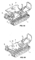
figure 7 shows a side orthographic view of a telescopic arm excavator according to the present invention; -
figure 8 shows a side orthographic view of a lifting platform according to the present invention; and -
figure 9 shows a side orthographic view of a crane according to the present invention. - With reference to
figures 1A, 1B ,2 and3 , a self-loading dumper, shown with thereference number 1, will be described in the following, as an example of self-propelled vehicle according to the invention. - It is mounted on
crawlers 2 and it is provided with ahopper 3 and a front bucket 4 mounted on a pair ofarms 5. - Moreover, it is meant to be controlled by an operator placed in an
operating cab 6 by means ofcontrols 7. - Crawlers 2 support a self-propelled
chassis 8, onto which thecab 6 is provided, and comprising a motor and all the controls of hopper and bucket. - Frontally, opposite the
cab 6, thechassis 8 supports asupport plate 9 entirely resting above thechassis 8. Theplate 9 is horizontally disposed and it is constrained to thecab 6. - Underneath it, the
dumper 1 comprises drive means, placed between thechassis 8 and thesupport plate 9, apt to rotate thesupport plate 9. In particular, said drive means comprises afifth wheel 10 fixed to theplate 9 by means of crown-disposed bolts. Thefifth wheel 10 is rotated by means of a motor-drivenpinion gear 11. - The
plate 9 receives saidhopper 3, and the respective controls thereon, so that thehopper 3 can be rotated relative tochassis 8 and crawlers, opposite to the operator. - In the present exemplificative embodiment, the
plate 9 is provided with supportingprojections 12 at the side edges thereof, supporting the articulatedarms 5 and the controls thereof, respectively. Accordingly,arms 5 and loading bucket 4 can rotate together with thehopper 3, thus always remaining in an optimal position for the material loading. - Anyhow, it is intended that the arms could be directly articulated to the
hopper 3 or, alternatively, to thechassis 2. - In the present exemplificative embodiment, the
arms 5 are optimally placed for being controlled in a position in which they provide the dumper a balanced configuration, even when thehopper 3 is rotated. - As in the present example, they could be telescopically extensible.
- The
fifth wheel 10 rotation axis A is substantially centered on theplate 9, in a vertical position. - It is intended that the shape of the hopper and of the bucket could be varied as preferred, in order to satisfy any operative requirement.
- With reference to figures from 4 to 6, in the following it will be described a second example of self-propelled vehicle according to the invention, in particular a crawlers-mounted self-propelled
lifter 1. - In the following, components common to both examples will be shown with the same reference numbers.
- Crawlers 2 support a self-propelled
chassis 8, onto which thecab 6 is provided, and comprising a motor and all the controls of device for grasping, lifting, and/or movingloads 3A, provided on thechassis 8 opposite thecab 6. -
Such device 3A comprises a telescopicallyextensible arm 5, formed by twoparts support plate 9 in correspondence of ahinge structure 5c. - On its distal end, the
arm 5 has a pair offorks 4a associated to a stoppingbulkhead 13. - The
forks 4a are of the type apt to lift standard pallets. Nevertheless, the device for grasping, lifting, and/or movingloads 3 could comprise any other loading implement. - In order to simplify loading and unloading,
forks 4a andbulkhead 13 are articulated at thetelescopic arm 5 distal end, and they can be controlled in their rotation above an horizontal axis, i.e. ahinge 15 onto which suitable actuators are mounted (not shown). - Underneath the
plate 9, thelifter 1 comprises drive means, apt to rotate thesupport plate 9. In particular, said drive means comprises afifth wheel 10 fixed to theplate 9 by means of crown-disposed bolts. Thefifth wheel 10 is rotated by a motor-drivenpinion gear 11. - The
plate 9 receives saidlifting device 3 and the respective controls thereon, so that thehopper 3 could be rotated relative tochassis 8 and crawlers, opposite to the operator. - The rotation axis A of the
fifth wheel 10 is substantially centered to theplate 9, in a vertical position. - In order to avoid the device for grasping, lifting, and/or moving loads to unbalance the self-propelled lifter, in particular when the arm 4 is extended and when it is rotated relative to the frontal position, the
plate 9 has anextension 9a placed according to a configuration opposed to the direction in to which the arm 4 projects. It comprises amobile compensator 14 that is translated according to the position of thearm 5,fork 4a and of the load lifted therefrom. - To this regard, the
compensator 14 could be extensible. - In this way, the
lifter 1 will not be allowed to tilt due to the laterally lifted weight. - It is intended that shape of the device for grasping, lifting, and/or moving loads could be varied as preferred in order to satisfy any operative requirement.
- With reference to
figure 7 , the vehicle, analogous to the preceding ones, comprises a lifting device 3a, the lifting member thereof being formed by abucket 4b articulated to a telescopicallyarm 5 distal end. - The
bucket 4b can thus be operated in its rotation above an horizontal axis, i.e. ahinge 15 in correspondence of which suitable actuators (not shown) are mounted, for simplifying the loading of the material to be displaced. - According to an analogous embodiment, the vehicle of
figure 8 is provided with a telescopic arm supporting alifting platform 4c, also articulated to thearm 5 distal so that it can be always maintained horizontal. - The
platform 4c can be formed by a safety cage. - With reference to
figure 9 , a self-propelled vehicle analogous to the preceding ones, comprises, at thetelescopically arm 5 distal end, a hoist 4d provided with ahook 16 connected to acable 17 end. The hoist 4d could be obviously also replaced by a winch or by any other lifting member. - In each described examples, the operating
cab 6 is disposed on thechassis 8 and not on therotating plate 9. Nevertheless, according to a modification of the invention, thecab 6 could be disposed above theplate 9 and together rotated, so that the operator is always directed towards the implemented mounted on the vehicle. - In this case, the compensator could be mounted at the back of the operating cab, and could be extensible rearwards, with an improved efficiency thanks to the rocker arm accordingly defined.
- The distance of the balance weight at the vehicle center could be manually modified by means by means of an automatic servomechanism, for enhancing balancing momentum.
- Moreover, It is intended that, in case, any of above described vehicle could be provided with stabilizing feet. Moreover, they can be provided with an universal quick coupling for a quick changing of implement at the arm.
- Furthermore, the crawler mounted vehicle could be of the fixed track-gauge type, variable track-gauge type or variable and/or enlarged track-gauge type.
- To the above-described self-propelled vehicle a person skilled in the art, in order to satisfy further and contingent needs, could effect several further modifications and variants, all however encompassed in the protective scope of the present invention, as defined by the appended claims.
Claims (14)
- A self-propelled vehicle (1), comprising:* a self-propelled chassis (8), on which a tool (3, 4; 4a; 4b; 4c; 4d) support plate (9) is placed; and* drive means (10, 11), placed between the chassis (8) and the support plate (9), apt to rotate the support plate (9).
- The self-propelled vehicle (1) according to claim 1, wherein the support plate (9) is placed in a front position.
- The self-propelled vehicle (1) according to claim 1 or 2, wherein the support plate (9) is horizontally disposed, entirely above the chassis (8).
- The self-propelled vehicle (1) according to any of the preceding claim, wherein the drive means comprises a fifth wheel (10) fixed to the support plate (9), and rotated by a motor-driven pinion gear (11).
- The self-propelled vehicle (1) according to claim 4, wherein the drive means (10, 11) defines a rotation axis (A) placed substantially at the support plate (9) center, in a vertical position.
- The self-propelled vehicle (1) according to any of the preceding claim, wherein the support plate (9) has respective supporting projections (12) for one or more tools (4; 4a; 4b; 4c; 4d) arms (5), at the side edges thereof.
- The self-propelled vehicle (1) according to claim 6, comprising an extensible arm (5), articulated at the base to a support plate (9), in correspondence of a hinge structure (5c).
- The self-propelled vehicle (1) according to claim 6, wherein said arm or arms (5) are telescopic.
- The self-propelled vehicle (1) according to claim 8, comprising a loading implement (4a; 4b; 4c; 4d) articulated at said extensible arm (5) distal end.
- The self-propelled vehicle (1) according to any of the preceding claim, wherein the support plate (9) supports mobile compensator (14) for compensating the weight of the load weighting on said arm or arms (5).
- The self-propelled vehicle (1) according to any of the preceding claim, wherein the chassis (8) is provided with crawlers (2).
- The self-propelled vehicle (1) according to any of the preceding claim, wherein the chassis (8) supports a cab (6), frontally and opposite to which, the chassis (8) supports said support plate (9) unconstrained from the cab (6).
- The self-propelled vehicle (1) according to any of claims 1 to 11, wherein said support plate (9) supports an operating cab (6) for an operator.
- The self-propelled vehicle (1) according to claims 11 and 13, wherein the compensator (14) is extensible at the back of the operating cab.
Applications Claiming Priority (2)
| Application Number | Priority Date | Filing Date | Title |
|---|---|---|---|
| ITRM20070558 ITRM20070558A1 (en) | 2007-10-24 | 2007-10-24 | SELF LOADING DUMPER WITH SWIVEL CASE |
| ITRM20070235 ITRM20070235U1 (en) | 2007-12-17 | 2007-12-17 | SELF-LIFTING LIFT |
Publications (1)
| Publication Number | Publication Date |
|---|---|
| EP2080730A1 true EP2080730A1 (en) | 2009-07-22 |
Family
ID=40679848
Family Applications (1)
| Application Number | Title | Priority Date | Filing Date |
|---|---|---|---|
| EP08167550A Withdrawn EP2080730A1 (en) | 2007-10-24 | 2008-10-24 | Self-propelled industrial vehicle |
Country Status (1)
| Country | Link |
|---|---|
| EP (1) | EP2080730A1 (en) |
Cited By (9)
| Publication number | Priority date | Publication date | Assignee | Title |
|---|---|---|---|---|
| CN102817390A (en) * | 2011-04-14 | 2012-12-12 | 哈尼施费格尔技术公司 | Swing automation for rope shovel |
| KR101329294B1 (en) | 2011-12-26 | 2013-11-13 | 윤길수 | Forklift for the excavator and the excavator having it |
| EP3034357A1 (en) * | 2014-12-17 | 2016-06-22 | Cormidi S.r.l. | Tool carrier platform for self-propelled vehicles and self-propelled vehicle including it |
| CN105984164A (en) * | 2015-02-10 | 2016-10-05 | 上海润寅制药设备有限公司 | Special automatic lifting machine for medicine production |
| US9745721B2 (en) | 2012-03-16 | 2017-08-29 | Harnischfeger Technologies, Inc. | Automated control of dipper swing for a shovel |
| KR20180003062U (en) * | 2018-01-02 | 2018-10-24 | 김대길 | Fork Lift Attachment for Excavators |
| CN114215132A (en) * | 2021-10-21 | 2022-03-22 | 朱伟燕 | Sediment ejection system for water conservancy construction |
| WO2022240208A1 (en) * | 2021-05-13 | 2022-11-17 | 현대두산인프라코어(주) | Excavator control system and excavator control method using same |
| US11565922B2 (en) * | 2018-03-30 | 2023-01-31 | Manitou Italia S.R.L. | Remote controlled telehandler |
Citations (9)
| Publication number | Priority date | Publication date | Assignee | Title |
|---|---|---|---|---|
| US2790568A (en) * | 1955-06-30 | 1957-04-30 | Vernon G Mandt | Swing-type material moving machine |
| US3240353A (en) * | 1963-03-08 | 1966-03-15 | Leavesley Engineering Ltd | Load responsive counterbalancing crane |
| US3329291A (en) * | 1965-08-27 | 1967-07-04 | Warner Swasey Co | Material handling apparatus |
| US3484005A (en) * | 1966-04-28 | 1969-12-16 | Poclain Sa | Earth working machine |
| GB1225268A (en) * | 1967-03-01 | 1971-03-17 | ||
| US4044902A (en) * | 1975-09-22 | 1977-08-30 | General Cable Corporation | Aerial lifting equipment |
| EP0184386A1 (en) * | 1984-12-01 | 1986-06-11 | J.C. Bamford Excavators Limited | Earth moving machine with counterweight |
| DE3611432A1 (en) * | 1986-04-05 | 1987-11-12 | Schaeff Karl Gmbh & Co | Swivel drive for a rotatable platform or suchlike supporting device, in particular for the swivelling bolster of a swing loader |
| EP0156546B1 (en) * | 1984-03-06 | 1988-09-28 | Kabushiki Kaisha Hikoma Seisakusho | Earth-working machine |
-
2008
- 2008-10-24 EP EP08167550A patent/EP2080730A1/en not_active Withdrawn
Patent Citations (9)
| Publication number | Priority date | Publication date | Assignee | Title |
|---|---|---|---|---|
| US2790568A (en) * | 1955-06-30 | 1957-04-30 | Vernon G Mandt | Swing-type material moving machine |
| US3240353A (en) * | 1963-03-08 | 1966-03-15 | Leavesley Engineering Ltd | Load responsive counterbalancing crane |
| US3329291A (en) * | 1965-08-27 | 1967-07-04 | Warner Swasey Co | Material handling apparatus |
| US3484005A (en) * | 1966-04-28 | 1969-12-16 | Poclain Sa | Earth working machine |
| GB1225268A (en) * | 1967-03-01 | 1971-03-17 | ||
| US4044902A (en) * | 1975-09-22 | 1977-08-30 | General Cable Corporation | Aerial lifting equipment |
| EP0156546B1 (en) * | 1984-03-06 | 1988-09-28 | Kabushiki Kaisha Hikoma Seisakusho | Earth-working machine |
| EP0184386A1 (en) * | 1984-12-01 | 1986-06-11 | J.C. Bamford Excavators Limited | Earth moving machine with counterweight |
| DE3611432A1 (en) * | 1986-04-05 | 1987-11-12 | Schaeff Karl Gmbh & Co | Swivel drive for a rotatable platform or suchlike supporting device, in particular for the swivelling bolster of a swing loader |
Cited By (16)
| Publication number | Priority date | Publication date | Assignee | Title |
|---|---|---|---|---|
| US12018463B2 (en) | 2011-04-14 | 2024-06-25 | Joy Global Surface Mining Inc | Swing automation for rope shovel |
| US9315967B2 (en) | 2011-04-14 | 2016-04-19 | Harnischfeger Technologies, Inc. | Swing automation for rope shovel |
| US9567725B2 (en) | 2011-04-14 | 2017-02-14 | Harnischfeger Technologies, Inc. | Swing automation for rope shovel |
| CN102817390B (en) * | 2011-04-14 | 2017-04-12 | 哈尼施费格尔技术公司 | Swing automation for rope shovel |
| CN102817390A (en) * | 2011-04-14 | 2012-12-12 | 哈尼施费格尔技术公司 | Swing automation for rope shovel |
| US10227754B2 (en) | 2011-04-14 | 2019-03-12 | Joy Global Surface Mining Inc | Swing automation for rope shovel |
| US11028560B2 (en) | 2011-04-14 | 2021-06-08 | Joy Global Surface Mining Inc | Swing automation for rope shovel |
| KR101329294B1 (en) | 2011-12-26 | 2013-11-13 | 윤길수 | Forklift for the excavator and the excavator having it |
| US9745721B2 (en) | 2012-03-16 | 2017-08-29 | Harnischfeger Technologies, Inc. | Automated control of dipper swing for a shovel |
| US10655301B2 (en) | 2012-03-16 | 2020-05-19 | Joy Global Surface Mining Inc | Automated control of dipper swing for a shovel |
| EP3034357A1 (en) * | 2014-12-17 | 2016-06-22 | Cormidi S.r.l. | Tool carrier platform for self-propelled vehicles and self-propelled vehicle including it |
| CN105984164A (en) * | 2015-02-10 | 2016-10-05 | 上海润寅制药设备有限公司 | Special automatic lifting machine for medicine production |
| KR20180003062U (en) * | 2018-01-02 | 2018-10-24 | 김대길 | Fork Lift Attachment for Excavators |
| US11565922B2 (en) * | 2018-03-30 | 2023-01-31 | Manitou Italia S.R.L. | Remote controlled telehandler |
| WO2022240208A1 (en) * | 2021-05-13 | 2022-11-17 | 현대두산인프라코어(주) | Excavator control system and excavator control method using same |
| CN114215132A (en) * | 2021-10-21 | 2022-03-22 | 朱伟燕 | Sediment ejection system for water conservancy construction |
Similar Documents
| Publication | Publication Date | Title |
|---|---|---|
| EP2080730A1 (en) | Self-propelled industrial vehicle | |
| US6571913B2 (en) | Multipurpose machine | |
| AU2002329704A1 (en) | Multipurpose machine | |
| EP0931759B1 (en) | Lateral jib for vertical mast mobile elevating work platform | |
| CN107531465B (en) | Body counterweight supporting device of crawler crane | |
| CA1148122A (en) | Multi-purpose utility vehicle | |
| US20050016946A1 (en) | Telehandler crane apparatus | |
| US7384233B2 (en) | Industrial truck | |
| JP4462633B2 (en) | Pallet truck | |
| JP2022541549A (en) | Excavator with lifting device for lifting pallets | |
| CN106006438B (en) | A kind of multifunction hydraulic crane | |
| US7163112B2 (en) | Material transloading equipment | |
| AU2020367535A1 (en) | Mobile crane | |
| JP2005096967A (en) | Reach stacker | |
| EP3405620B1 (en) | A loader vehicle | |
| NL1036935C2 (en) | LIFTING DEVICE AND LIFTING FOR USE IN A LIFTING DEVICE. | |
| GB2066189A (en) | Multi-purpose utility vehicle | |
| JP7392820B2 (en) | Crane connecting beam installation method | |
| JPH1054055A (en) | Lifting-lowering controller for working machine | |
| DK181322B1 (en) | Support device for a truck comprising a truck mounted crane | |
| EP0080002B1 (en) | Mobile yard crane for the handling of containers | |
| US20220282447A1 (en) | Material handler skip pan | |
| RU1776630C (en) | Self-propelled load lifting crane | |
| JP2004345855A (en) | Working vehicle | |
| JPH0514095U (en) | Self-propelled work machine |
Legal Events
| Date | Code | Title | Description |
|---|---|---|---|
| PUAI | Public reference made under article 153(3) epc to a published international application that has entered the european phase |
Free format text: ORIGINAL CODE: 0009012 |
|
| AK | Designated contracting states |
Kind code of ref document: A1 Designated state(s): AT BE BG CH CY CZ DE DK EE ES FI FR GB GR HR HU IE IS IT LI LT LU LV MC MT NL NO PL PT RO SE SI SK TR |
|
| AX | Request for extension of the european patent |
Extension state: AL BA MK RS |
|
| AKX | Designation fees paid | ||
| REG | Reference to a national code |
Ref country code: DE Ref legal event code: 8566 |
|
| STAA | Information on the status of an ep patent application or granted ep patent |
Free format text: STATUS: THE APPLICATION IS DEEMED TO BE WITHDRAWN |
|
| 18D | Application deemed to be withdrawn |
Effective date: 20100123 |