EP2080720A1 - Device for monitoring conveyor belt - Google Patents
Device for monitoring conveyor belt Download PDFInfo
- Publication number
- EP2080720A1 EP2080720A1 EP07831660A EP07831660A EP2080720A1 EP 2080720 A1 EP2080720 A1 EP 2080720A1 EP 07831660 A EP07831660 A EP 07831660A EP 07831660 A EP07831660 A EP 07831660A EP 2080720 A1 EP2080720 A1 EP 2080720A1
- Authority
- EP
- European Patent Office
- Prior art keywords
- conveyor belt
- shaft
- detector
- sensor
- roller
- Prior art date
- Legal status (The legal status is an assumption and is not a legal conclusion. Google has not performed a legal analysis and makes no representation as to the accuracy of the status listed.)
- Granted
Links
- 238000012544 monitoring process Methods 0.000 title claims abstract description 8
- 229920001903 high density polyethylene Polymers 0.000 description 4
- 239000004700 high-density polyethylene Substances 0.000 description 4
- 239000000463 material Substances 0.000 description 3
- 229920006324 polyoxymethylene Polymers 0.000 description 2
- 229930182556 Polyacetal Natural products 0.000 description 1
- 239000000956 alloy Substances 0.000 description 1
- 229910045601 alloy Inorganic materials 0.000 description 1
- 239000004020 conductor Substances 0.000 description 1
- 229920001971 elastomer Polymers 0.000 description 1
- 239000005060 rubber Substances 0.000 description 1
- XLYOFNOQVPJJNP-UHFFFAOYSA-N water Substances O XLYOFNOQVPJJNP-UHFFFAOYSA-N 0.000 description 1
Images



Classifications
-
- B—PERFORMING OPERATIONS; TRANSPORTING
- B65—CONVEYING; PACKING; STORING; HANDLING THIN OR FILAMENTARY MATERIAL
- B65G—TRANSPORT OR STORAGE DEVICES, e.g. CONVEYORS FOR LOADING OR TIPPING, SHOP CONVEYOR SYSTEMS OR PNEUMATIC TUBE CONVEYORS
- B65G43/00—Control devices, e.g. for safety, warning or fault-correcting
- B65G43/02—Control devices, e.g. for safety, warning or fault-correcting detecting dangerous physical condition of load carriers, e.g. for interrupting the drive in the event of overheating
Definitions
- the present invention relates to a device for monitoring a conveyor belt.
- an object to be detected is embedded in or attached on the conveyor belt.
- a sensor for detecting the object is fixed to a stationary object close to the moving object to the conveyor belt. Owing to variation in information detected by the sensor, variations in the shape of the conveyor belt such as meandering, a crack and wear can be detected.
- JP6-48533A discloses magnets as object to be detected.
- a sensor detects magnetic force, so that the conditions of a conveyor belt can be grasped with variation in magnetic force
- a gauss meter, a loop coil and a MI sensor magnetic-impedance sensor
- JP6-48533A discloses that the sensor is provided in a roller or a pulley.
- JP6-48533A merely discloses that the sensor is provided in the roller and pulley, but there is no detailed structure on how to fix the sensor in the rotating roller or how to pull out a cable extending from the sensor.
- the belt does not always contact the roller.
- the distance between the sensor and the belt varies when the roller contacts the belt and when the roller does not contact the belt. Meandering of the belt can be detected, but it would be very difficult to exactly detect other variations in shape of the belt such as wear.
- Fig. 1 is a vertical sectional front view of a conveyor belt comprising the first embodiment of a device for monitoring the conveyor belt according to the present invention with a monitor for the conveyor belt.
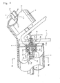
- Fig. 2 is an enlarged partially cutaway view showing the section A in Fig. 1 .
- Fig. 3 is a vertical sectional view taken along the line III-III in Fig. 2 .
- Fig. 4 is an exploded perspective view showing parts in the section A in Fig.1 .
- Fig. 5 is a schematic side view of a tubular conveyor belt to which the present invention applies.
- Fig. 6 is an enlarged vertical sectional view taken along the line VI-VI in Fig. 5 .
- Figs. 1-4 show a conveyor belt comprising the first embodiment of the present Invention.
- Fig. 1 at plural positions along the length of a horizontal support frame 1 of the conveyor belt, there are a pair of lower inner brackets 2,2 and a pair of higher outer brackets 3,3 in the middle and side of the support frame 1 respectively.
- a guide roller 4 is rotatively mounted around a shaft 5, and between the inner bracket 2 and the outer bracket 3, a roller 4 is rotatively mounted around a shaft 5 and tilted to rise sideward.
- the roller 4 may be made of HDPE (high density polyethylene), PP and ABS which are excellent in processing capability, strength, sliding performance and cost.
- the roller may be made of POM (polyacetal) which is better than HDPE, PP and ABS in sliding performance.
- PA66 and PA6 may be used and is better than HDPE, PP and ABS in heat resistance and sliding performance.
- Magnetized electric conductors such as AI alloy may be used.
- An endless trough-like conveyor belt 6 is placed on the rollers 4 and runs smoothly by rotating the rollers 4 around the shaft 5.
- the conveyor belt 6 is wound between a driving pulley and a driven pulley (not shown). Materials are held on the middle of the upper surface of the conveyor belt 6, conveyed along a going path from one end to the other end and thrown away onto a hopper. Then, the conveyor belt 6 is guided through guide rollers (not shown) under the support frame 1 along a returning path.
- the roller 4 is hollow and has an elongate sensor 7 on the shaft 5 therein.
- the detecting surface of the sensor 6 faces the lower surface of the conveyor belt 6.
- a cable 8 coupled at one end to the sensor 7 extends from the axial end of the shaft 5 and is connected to a signal processor 9.
- the sensor 7 may be a magnetic sensor such as a gauss meter, a loop coil and an MI sensor if magnets are used as object to be detected.
- a signal detected by the sensor 7 is converted to an electric signal by a signal processor 9 and fed to a monitor 11 via a cable 10.
- the conveyor belt 6 can be monitored continuously along the width of the belt 6.
- Figs. 2-4 show an internal structure of the roller 4 in detail.
- the roller 4 comprises a hollow roller body 12 and an end plate 13 fixed to each end of the roller body 12.
- An outward flange 13a of the end plate 13 is fixed to the inner surface of the roller body 4 by shrinkage fit and a tubular portion 13b is provided in the middle.
- a hole 13c is formed in the middle of the tubular portion 13b.
- the roller 4 is rotatively mounted around the shaft 5 via a ball bearing 14.
- a combined labyrinth seal 15 over the ball bearing 14 provides water resistance on the bearing part.
- a cavity 5a is formed at one end of the shaft 5.
- a closure 16 engages in a thread bore 5b of the cavity 5a.
- the closure 16 projecting outward from the shaft 5 is not circular in a vertical cross section with a pair of flat surfaces 16a,16a on the outer circumferential surface.
- the noncircular closure 16 engages in a noncircular axial hole 2a of the bracket 2, so that the shaft 5 is positioned with respect to the bracket 2 to allow the sensor 7 mounted on the shaft 5 to face the conveyor belt 6 anytime.
- the closure 16 at the end of the shaft 5 is noncircular and engages in the noncircular axial hole 2a of the bracket 2 to allow the sensor 7 to face the conveyor belt 6 anytime.
- a flat surface 5c is formed on the outer circumferential surface of the shaft 5.
- a rectangular case 7a including the sensor 7 is placed on the flat surface 5c along the length of the shaft 5.
- a U-like piece 17 engages on the shaft 5, and the ends of the U-like piece 17 pass through an outward flange 7b at the lower end of the case 7a. The ends of the U-like piece 17 are tightened with nuts 18. So the sensor 5 is firmly fixed to the shaft 5.
- a through hole 5d which communicates with the cavity 5a and opens in the outer circumferential surface of the shaft 5.
- a water-proof grommet 19 fits in the through hole 5d.
- the cable 8 from one end of the case 7a extends through the through hole 5d, the grommet 19, the cavity 5a, the through hole 16b at the center of the closure 16 and a grommet 20 fitting in the opening end of the through hole 16b, and is pulled out.
- the case 7a for the sensor 7 is mounted to the shaft 5 with a mounting tool 17.
- the cable and the closure 16 are mounted as above, they are inserted in the roller 4 via the mounting hole 13c of the roller 4 and the sensor 7 is placed at a desired position in the roller 4.
- the ball bearing 14 and the seal 15 are mounted in the tubular portion 13b at each end of the roller 4.
- the ball bearing 14 and seal 15 may have been provided at one end of the roller 4 in advance.
- a lower non-conveying surface 6b of the conveyor belt 6 that conveys materials on the upper surface goes on the roller 4 as shown in an arrow.
- a magnet M embedded in the conveyor belt 6 is detected by the sensor 7, and a detected signal is sent to the signal processor 9 via the cable 8. It is converted into an electric signal which is fed into the monitor 11 via the cable 10, so that meandering, a crack or wear is detected certainly.
- magnet M including magnetic rubbers
- what transmits sound, light, vibration, magnetic force or electromagnetic wave may be used, and a detector that receives such a signal may be used.
- the present invention may apply not only to a flat conveyor belt in Fig. 1 , but also to a tubular conveyor belt in Figs. 5 and 6 .
- an endless conveyor belt 21 is wound around a front end pulley 22 and a rear end pulley 23. Between the front end pulley 22 and the rear end pulley 23, the conveyor belt 21 is rolled up into a tube with an overlapped portion 28 by passing though a number of guide frames 25,26,27 in which a plurality of guide rollers 24 is arranged like a circle or a trough. Materials are enclosed in the conveyor belt 21 and conveyed with the closed overlapped portion 28.
- the intermediate guide frame 26 comprises an upper chamber 26b and a lower chamber 26c each having an opening 26a in the middle through which the conveyor belt 21 goes.
- the plurality of guide rollers 24 is arranged around the opening 26a in each of the chambers 26b,26c.
- a going belt 21a of the conveyor belt 21 passes through the opening 26a in the upper chamber 26b, and a returning belt 21b passes through the opening 26a in the lower chamber 26c, so that the belts 21a,21b are kept like a tube.
- a shaft 31 for rotatively mounting the guide roller 24 to a bracket 31 in the guide frame 26.
- a detector (not shown) similar to the sensor 7 in the first embodiment may be provided as well as those in the first embodiment.
Landscapes
- Control Of Conveyors (AREA)
- Structure Of Belt Conveyors (AREA)
Abstract
Description
- The present invention relates to a device for monitoring a conveyor belt.
- In such a device for monitoring a conveyor belt, an object to be detected is embedded in or attached on the conveyor belt. A sensor for detecting the object is fixed to a stationary object close to the moving object to the conveyor belt. Owing to variation in information detected by the sensor, variations in the shape of the conveyor belt such as meandering, a crack and wear can be detected.
JP6-48533A
A gauss meter, a loop coil and a MI sensor (magnetic-impedance sensor) are used as sensor. -
JP6-48533A -
JP6-48533A - In the publication, the belt does not always contact the roller. The distance between the sensor and the belt varies when the roller contacts the belt and when the roller does not contact the belt. Meandering of the belt can be detected, but it would be very difficult to exactly detect other variations in shape of the belt such as wear.
- In view of the disadvantages in the prior art, it is an object of the invention to provide a device for monitoring a conveyor belt, a sensor being easily mounted to a stationary structure without special mounting means, the shape of the belt being detected with high accuracy.
-
Fig. 1 is a vertical sectional front view of a conveyor belt comprising the first embodiment of a device for monitoring the conveyor belt according to the present invention with a monitor for the conveyor belt. -
Fig. 2 is an enlarged partially cutaway view showing the section A inFig. 1 . -
Fig. 3 is a vertical sectional view taken along the line III-III inFig. 2 . -
Fig. 4 is an exploded perspective view showing parts in the section A inFig.1 . -
Fig. 5 is a schematic side view of a tubular conveyor belt to which the present invention applies. -
Fig. 6 is an enlarged vertical sectional view taken along the line VI-VI inFig. 5 . -
Figs. 1-4 show a conveyor belt comprising the first embodiment of the present Invention.
InFig. 1 , at plural positions along the length of ahorizontal support frame 1 of the conveyor belt, there are a pair of lowerinner brackets outer brackets support frame 1 respectively. - Between the
inner bracket 2 and theinner bracket 2, aguide roller 4 is rotatively mounted around ashaft 5, and between theinner bracket 2 and theouter bracket 3, aroller 4 is rotatively mounted around ashaft 5 and tilted to rise sideward. - The
roller 4 may be made of HDPE (high density polyethylene), PP and ABS which are excellent in processing capability, strength, sliding performance and cost.
The roller may be made of POM (polyacetal) which is better than HDPE, PP and ABS in sliding performance.
PA66 and PA6 may be used and is better than HDPE, PP and ABS in heat resistance and sliding performance.
Magnetized electric conductors such as AI alloy may be used. - An endless trough-
like conveyor belt 6 is placed on therollers 4 and runs smoothly by rotating therollers 4 around theshaft 5. - The
conveyor belt 6 is wound between a driving pulley and a driven pulley (not shown). Materials are held on the middle of the upper surface of theconveyor belt 6, conveyed along a going path from one end to the other end and thrown away onto a hopper. Then, theconveyor belt 6 is guided through guide rollers (not shown) under thesupport frame 1 along a returning path. - In
Figs. 2-6 , theroller 4 is hollow and has anelongate sensor 7 on theshaft 5 therein. The detecting surface of thesensor 6 faces the lower surface of theconveyor belt 6.
Acable 8 coupled at one end to thesensor 7 extends from the axial end of theshaft 5 and is connected to a signal processor 9. Thesensor 7 may be a magnetic sensor such as a gauss meter, a loop coil and an MI sensor if magnets are used as object to be detected. - A signal detected by the
sensor 7 is converted to an electric signal by a signal processor 9 and fed to a monitor 11 via acable 10. Thus, theconveyor belt 6 can be monitored continuously along the width of thebelt 6. -
Figs. 2-4 show an internal structure of theroller 4 in detail. Theroller 4 comprises ahollow roller body 12 and anend plate 13 fixed to each end of theroller body 12. An outward flange 13a of theend plate 13 is fixed to the inner surface of theroller body 4 by shrinkage fit and atubular portion 13b is provided in the middle. A hole 13c is formed in the middle of thetubular portion 13b. - The
roller 4 is rotatively mounted around theshaft 5 via a ball bearing 14. A combinedlabyrinth seal 15 over the ball bearing 14 provides water resistance on the bearing part. - A cavity 5a is formed at one end of the
shaft 5. Aclosure 16 engages in athread bore 5b of the cavity 5a. - The
closure 16 projecting outward from theshaft 5 is not circular in a vertical cross section with a pair of flat surfaces 16a,16a on the outer circumferential surface. Thenoncircular closure 16 engages in a noncircular axial hole 2a of thebracket 2, so that theshaft 5 is positioned with respect to thebracket 2 to allow thesensor 7 mounted on theshaft 5 to face theconveyor belt 6 anytime.
Specifically, theclosure 16 at the end of theshaft 5 is noncircular and engages in the noncircular axial hole 2a of thebracket 2 to allow thesensor 7 to face theconveyor belt 6 anytime. - A
flat surface 5c is formed on the outer circumferential surface of theshaft 5. Arectangular case 7a including thesensor 7 is placed on theflat surface 5c along the length of theshaft 5. A U-likepiece 17 engages on theshaft 5, and the ends of the U-likepiece 17 pass through anoutward flange 7b at the lower end of thecase 7a. The ends of the U-likepiece 17 are tightened withnuts 18. So thesensor 5 is firmly fixed to theshaft 5. - At the end of the
shaft 5, there is formed a throughhole 5d which communicates with the cavity 5a and opens in the outer circumferential surface of theshaft 5. A water-proof grommet 19 fits in the throughhole 5d.
Thecable 8 from one end of thecase 7a extends through the throughhole 5d, thegrommet 19, the cavity 5a, the through hole 16b at the center of theclosure 16 and agrommet 20 fitting in the opening end of the through hole 16b, and is pulled out. - For assembling, the
case 7a for thesensor 7 is mounted to theshaft 5 with amounting tool 17. After the cable and theclosure 16 are mounted as above, they are inserted in theroller 4 via the mounting hole 13c of theroller 4 and thesensor 7 is placed at a desired position in theroller 4. The ball bearing 14 and theseal 15 are mounted in thetubular portion 13b at each end of theroller 4. The ball bearing 14 andseal 15 may have been provided at one end of theroller 4 in advance. - Only the
horizontal roller 4 is shown in detail in the drawings, but thetilted roller 4 is provided at different posture with structure similar to thehorizontal roller 4. - In
Fig. 3 , a lowernon-conveying surface 6b of theconveyor belt 6 that conveys materials on the upper surface goes on theroller 4 as shown in an arrow. A magnet M embedded in theconveyor belt 6 is detected by thesensor 7, and a detected signal is sent to the signal processor 9 via thecable 8. It is converted into an electric signal which is fed into the monitor 11 via thecable 10, so that meandering, a crack or wear is detected certainly. - Besides the magnet M including magnetic rubbers, what transmits sound, light, vibration, magnetic force or electromagnetic wave may be used, and a detector that receives such a signal may be used.
- The present invention may apply not only to a flat conveyor belt in
Fig. 1 , but also to a tubular conveyor belt inFigs. 5 and 6 .
In the tubular conveyor belt, anendless conveyor belt 21 is wound around afront end pulley 22 and arear end pulley 23. Between thefront end pulley 22 and therear end pulley 23, theconveyor belt 21 is rolled up into a tube with an overlappedportion 28 by passing though a number of guide frames 25,26,27 in which a plurality ofguide rollers 24 is arranged like a circle or a trough. Materials are enclosed in theconveyor belt 21 and conveyed with the closed overlappedportion 28. - In
Fig. 6 , theintermediate guide frame 26 comprises anupper chamber 26b and a lower chamber 26c each having anopening 26a in the middle through which theconveyor belt 21 goes. The plurality ofguide rollers 24 is arranged around theopening 26a in each of thechambers 26b,26c. - A going
belt 21a of theconveyor belt 21 passes through theopening 26a in theupper chamber 26b, and a returningbelt 21b passes through theopening 26a in the lower chamber 26c, so that thebelts - In the
guide roller 24 of the tubular conveyor belt, there is provided ashaft 31 for rotatively mounting theguide roller 24 to abracket 31 in theguide frame 26. A detector (not shown) similar to thesensor 7 in the first embodiment may be provided as well as those in the first embodiment.
Claims (7)
- A device for monitoring a conveyor belt, comprising a structure; a shaft mounted to the structure; a guide roller supported by the shaft; and an endless conveyor belt guided on and by the guide roller, the belt having object to be detected, the structure having a detector, variation of the object caused by variation of the natures in the conveyor belt being detected by the detector to detect the variation of the natures of the conveyor belt, characterized in that:the shaft is supported on the structure and the guide roller is rotatively supported around the shaft via a bearing to form a space in the guide roller, the detector being foxed to the shaft in the spece.
- The device of claim 1 wherein a cavity which is open toward an axial end is formed at the end of the shaft, a through hole which communicates with the cavity being formed through the circumference of the shaft, a cable from the detector being pulled out of the axial end via the through hole and the cavity.
- The device of claim 1 or 2 wherein a plurality of shafts and a plurality of guide rollers are provided in the structure, the detector being provided on at least one of the shafts.
- The device of any one of claims 1 to 3 wherein a plurality of shaft and a plurality of guide rollers are provided along the width of the conveyor belt during conveying, the detector being provided on the shaft in the space in each of the guide rollers.
- The device of any one of claims 1 to 4 wherein the guide roller including the detector contacts the conveyor belt anytime.
- The device of any one of claims 1 to 5 wherein at the ends of the structure and shaft, there is positioning means positioning the detector mounted on the shaft to face an non-conveyed surface of the conveyor belt.
- The device of claim 6 wherein the positioning means comprises a noncircular portion on the outer circumferential surface of the end of the shaft; and a noncircular hole fitting the noncircular portion, engagement of both achieving positioning.
Applications Claiming Priority (2)
| Application Number | Priority Date | Filing Date | Title |
|---|---|---|---|
| JP2006304943 | 2006-11-10 | ||
| PCT/JP2007/071930 WO2008056807A1 (en) | 2006-11-10 | 2007-11-12 | Device for monitoring conveyor belt |
Publications (3)
| Publication Number | Publication Date |
|---|---|
| EP2080720A1 true EP2080720A1 (en) | 2009-07-22 |
| EP2080720A4 EP2080720A4 (en) | 2012-02-29 |
| EP2080720B1 EP2080720B1 (en) | 2013-04-03 |
Family
ID=39364612
Family Applications (1)
| Application Number | Title | Priority Date | Filing Date |
|---|---|---|---|
| EP07831660A Not-in-force EP2080720B1 (en) | 2006-11-10 | 2007-11-12 | Device for monitoring conveyor belt |
Country Status (6)
| Country | Link |
|---|---|
| US (1) | US8157085B2 (en) |
| EP (1) | EP2080720B1 (en) |
| JP (1) | JPWO2008056807A1 (en) |
| CN (1) | CN101535154B (en) |
| AU (1) | AU2007318457B2 (en) |
| WO (1) | WO2008056807A1 (en) |
Families Citing this family (9)
| Publication number | Priority date | Publication date | Assignee | Title |
|---|---|---|---|---|
| US8604776B2 (en) * | 2010-06-24 | 2013-12-10 | Schrader Electronics Ltd. | Power transmission monitoring and maintenance systems and methods |
| JP5957215B2 (en) * | 2011-12-02 | 2016-07-27 | 株式会社ブリヂストン | Conveyor belt equipment |
| JP2015048213A (en) * | 2013-09-02 | 2015-03-16 | 明星セメント株式会社 | Belt conveyor and operation method of the same |
| BR112017004309B1 (en) | 2014-09-05 | 2022-09-20 | Contitech Transportbandsysteme Gmbh | METHOD FOR DETECTION OF LONGITUDINAL TEARS AND BELT ORIENTATION MONITORING OF A TUBULAR CONVEYOR BELT |
| WO2017020080A1 (en) * | 2015-08-03 | 2017-02-09 | Mine Sensor Holdings Pty Ltd | Transponder, transponder assembly, transceiver, monitoring system, method of installation and kit for obtaining sensor data related to an idler roller of a belt conveyor system |
| JP6866697B2 (en) * | 2017-03-08 | 2021-04-28 | 中国電力株式会社 | Temperature detection line mounting jig, temperature detection device and belt conveyor device |
| CN109018915B (en) * | 2018-06-27 | 2020-03-17 | 中国矿业大学 | Movable belt conveyor broken belt protection and catching system |
| CN112124901A (en) * | 2020-10-12 | 2020-12-25 | 潍坊工商职业学院 | Mechanical equipment fault location and alarm protection device |
| KR102600415B1 (en) * | 2022-10-12 | 2023-11-08 | 성균관대학교산학협력단 | Driving belt inspection device and mehtods of wafer transfer module |
Family Cites Families (21)
| Publication number | Priority date | Publication date | Assignee | Title |
|---|---|---|---|---|
| DE3335766A1 (en) * | 1983-10-01 | 1985-04-11 | Leybold-Heraeus GmbH, 5000 Köln | ARRANGEMENT FOR THE ELECTRICAL MEASUREMENT OF LAYER THICKNESSES ON RUNNING TAPES |
| JPS644735Y2 (en) | 1984-12-28 | 1989-02-07 | ||
| US4780746A (en) * | 1987-07-20 | 1988-10-25 | Xerox Corporation | Idler roll |
| CN2085787U (en) * | 1990-03-29 | 1991-10-02 | 上海海运学院 | Automatic detecting and controlling device for longitudinal tear of rubber belt of rubber coated draper |
| JP3156168B2 (en) * | 1992-07-06 | 2001-04-16 | 株式会社三井三池製作所 | Method and apparatus for detecting twist in pipe conveyor |
| JPH0648533A (en) | 1992-07-24 | 1994-02-22 | Nkk Corp | Belt meandering detecting method |
| DE19504779C2 (en) * | 1995-02-14 | 1997-12-04 | Bochumer Eisen Heintzmann | Process for operating a continuously operating extraction device for mineral raw materials that are present in the seam and the extraction device set up for carrying out the method |
| DE19639090C2 (en) * | 1996-09-24 | 2003-06-18 | Elektromechanische Systeme Gmb | Belt conveyors |
| US6341522B1 (en) * | 1996-12-13 | 2002-01-29 | Measurex Corporation | Water weight sensor array imbedded in a sheetmaking machine roll |
| JP3798494B2 (en) * | 1997-02-12 | 2006-07-19 | Ntn株式会社 | Conveyor roller abnormality detection device |
| JP4172606B2 (en) * | 1998-08-25 | 2008-10-29 | オークラ輸送機株式会社 | Roller device and roller conveyor |
| US6441904B1 (en) * | 1999-03-04 | 2002-08-27 | Metso Paper Automation Oy | Method and apparatus for measuring properties of a moving fiber web |
| US6390287B2 (en) * | 1999-06-10 | 2002-05-21 | The Robbins Company | Self-adjusting carrying idler assembly |
| US6752908B2 (en) * | 2001-06-01 | 2004-06-22 | Stowe Woodward, Llc | Shoe press belt with system for detecting operational parameters |
| KR100403605B1 (en) * | 2002-04-10 | 2003-10-30 | Samsung Electronics Co Ltd | Method for driving belt |
| US7132943B2 (en) * | 2002-11-07 | 2006-11-07 | The Johns Hopkins University | Moving belt sensor |
| JP3673923B2 (en) * | 2002-12-09 | 2005-07-20 | 伊東電機株式会社 | Roller device and method for manufacturing roller device |
| US7275637B2 (en) * | 2005-02-24 | 2007-10-02 | Barry Charles Brown | Multi-channel conveyor belt condition monitoring |
| JP4932222B2 (en) * | 2005-04-13 | 2012-05-16 | 株式会社ブリヂストン | Conveyor belt wear detection device |
| US7572214B2 (en) * | 2005-05-04 | 2009-08-11 | Stowe Woodward L.L.C. | Suction roll with sensors for detecting operational parameters having apertures |
| DE102005055655A1 (en) * | 2005-11-22 | 2007-05-31 | Siemens Ag | Conveyor belt condition determining device for e.g. mining industry, has evaluating device designed such that it compares two-dimensional images of belt sections detected by detection device with reference images assigned to sections |
-
2007
- 2007-11-12 EP EP07831660A patent/EP2080720B1/en not_active Not-in-force
- 2007-11-12 US US12/513,082 patent/US8157085B2/en not_active Expired - Fee Related
- 2007-11-12 JP JP2008543154A patent/JPWO2008056807A1/en active Pending
- 2007-11-12 CN CN2007800418006A patent/CN101535154B/en not_active Expired - Fee Related
- 2007-11-12 WO PCT/JP2007/071930 patent/WO2008056807A1/en not_active Ceased
- 2007-11-12 AU AU2007318457A patent/AU2007318457B2/en not_active Ceased
Non-Patent Citations (2)
| Title |
|---|
| No further relevant documents disclosed * |
| See also references of WO2008056807A1 * |
Also Published As
| Publication number | Publication date |
|---|---|
| EP2080720B1 (en) | 2013-04-03 |
| EP2080720A4 (en) | 2012-02-29 |
| US20100089725A1 (en) | 2010-04-15 |
| JPWO2008056807A1 (en) | 2010-02-25 |
| AU2007318457A1 (en) | 2008-05-15 |
| US8157085B2 (en) | 2012-04-17 |
| AU2007318457B2 (en) | 2010-12-16 |
| CN101535154B (en) | 2011-08-24 |
| WO2008056807A1 (en) | 2008-05-15 |
| CN101535154A (en) | 2009-09-16 |
Similar Documents
| Publication | Publication Date | Title |
|---|---|---|
| US8157085B2 (en) | Device for monitoring a conveyor belt | |
| AU2012344875B2 (en) | Conveyor belt apparatus | |
| US6561451B1 (en) | Measuring cable travel sensor with longitudinal drive for the cable drum | |
| US5089776A (en) | Apparatus for detecting defects in a moving steel strip with a magnetizing yoke and a sensor placed on opposite sides of the strip | |
| US20160320266A1 (en) | Pipe outer surface inspection apparatus | |
| JP2009132501A (en) | Pipe conveyor belt | |
| EP0817972B1 (en) | Bearing assembly having integrated speed sensor | |
| US20090277693A1 (en) | Apparatus and Method for Weighing a Product Flow | |
| JP6968400B2 (en) | Electric belt meandering adjustment device | |
| AU2018250413A1 (en) | Pipe belt orientation monitoring | |
| CN210479989U (en) | Carrier roller for speed detection and belt speed detection device of belt conveyor | |
| FR2821904A1 (en) | INSTRUMENT BEARING ROLLER DEVICE | |
| CN101802453B (en) | Sealed linear actuator unit | |
| JP4101110B2 (en) | Eddy current flaw detection sensor | |
| US5927862A (en) | Bearing | |
| EP2049418B1 (en) | Method for controlling the tension of a chain of a bucket carousel | |
| JP4723752B2 (en) | X-ray inspection equipment | |
| CN101517139B (en) | yarn detector | |
| WO2007117021A1 (en) | Pipe conveyor | |
| KR101196399B1 (en) | Meandering sensing apparatus of conveyer belt and belt conveyer system with the same | |
| JP6450236B2 (en) | Steel cord conveyor belt longitudinal crack detection device and steel cord conveyor belt longitudinal crack detection system | |
| KR20150104907A (en) | Conveyor system for metal detector | |
| CN111573195A (en) | Conveying equipment capable of automatically correcting deviation of conveying belt | |
| JPH04106016A (en) | Torsion detecting method for pipe conveyor | |
| CN222757393U (en) | Conveying device and guiding mechanism thereof |
Legal Events
| Date | Code | Title | Description |
|---|---|---|---|
| PUAI | Public reference made under article 153(3) epc to a published international application that has entered the european phase |
Free format text: ORIGINAL CODE: 0009012 |
|
| 17P | Request for examination filed |
Effective date: 20090522 |
|
| AK | Designated contracting states |
Kind code of ref document: A1 Designated state(s): AT BE BG CH CY CZ DE DK EE ES FI FR GB GR HU IE IS IT LI LT LU LV MC MT NL PL PT RO SE SI SK TR |
|
| A4 | Supplementary search report drawn up and despatched |
Effective date: 20120131 |
|
| RIC1 | Information provided on ipc code assigned before grant |
Ipc: B65G 43/02 20060101AFI20120125BHEP |
|
| DAX | Request for extension of the european patent (deleted) | ||
| GRAP | Despatch of communication of intention to grant a patent |
Free format text: ORIGINAL CODE: EPIDOSNIGR1 |
|
| GRAS | Grant fee paid |
Free format text: ORIGINAL CODE: EPIDOSNIGR3 |
|
| GRAA | (expected) grant |
Free format text: ORIGINAL CODE: 0009210 |
|
| AK | Designated contracting states |
Kind code of ref document: B1 Designated state(s): AT BE BG CH CY CZ DE DK EE ES FI FR GB GR HU IE IS IT LI LT LU LV MC MT NL PL PT RO SE SI SK TR |
|
| REG | Reference to a national code |
Ref country code: GB Ref legal event code: FG4D |
|
| REG | Reference to a national code |
Ref country code: CH Ref legal event code: EP Ref country code: AT Ref legal event code: REF Ref document number: 604589 Country of ref document: AT Kind code of ref document: T Effective date: 20130415 |
|
| REG | Reference to a national code |
Ref country code: IE Ref legal event code: FG4D |
|
| REG | Reference to a national code |
Ref country code: DE Ref legal event code: R096 Ref document number: 602007029507 Country of ref document: DE Effective date: 20130529 |
|
| REG | Reference to a national code |
Ref country code: AT Ref legal event code: MK05 Ref document number: 604589 Country of ref document: AT Kind code of ref document: T Effective date: 20130403 |
|
| PG25 | Lapsed in a contracting state [announced via postgrant information from national office to epo] |
Ref country code: SI Free format text: LAPSE BECAUSE OF FAILURE TO SUBMIT A TRANSLATION OF THE DESCRIPTION OR TO PAY THE FEE WITHIN THE PRESCRIBED TIME-LIMIT Effective date: 20130403 |
|
| REG | Reference to a national code |
Ref country code: NL Ref legal event code: VDEP Effective date: 20130403 |
|
| REG | Reference to a national code |
Ref country code: LT Ref legal event code: MG4D |
|
| PG25 | Lapsed in a contracting state [announced via postgrant information from national office to epo] |
Ref country code: PT Free format text: LAPSE BECAUSE OF FAILURE TO SUBMIT A TRANSLATION OF THE DESCRIPTION OR TO PAY THE FEE WITHIN THE PRESCRIBED TIME-LIMIT Effective date: 20130805 Ref country code: IS Free format text: LAPSE BECAUSE OF FAILURE TO SUBMIT A TRANSLATION OF THE DESCRIPTION OR TO PAY THE FEE WITHIN THE PRESCRIBED TIME-LIMIT Effective date: 20130803 Ref country code: SE Free format text: LAPSE BECAUSE OF FAILURE TO SUBMIT A TRANSLATION OF THE DESCRIPTION OR TO PAY THE FEE WITHIN THE PRESCRIBED TIME-LIMIT Effective date: 20130403 Ref country code: BE Free format text: LAPSE BECAUSE OF FAILURE TO SUBMIT A TRANSLATION OF THE DESCRIPTION OR TO PAY THE FEE WITHIN THE PRESCRIBED TIME-LIMIT Effective date: 20130403 Ref country code: NL Free format text: LAPSE BECAUSE OF FAILURE TO SUBMIT A TRANSLATION OF THE DESCRIPTION OR TO PAY THE FEE WITHIN THE PRESCRIBED TIME-LIMIT Effective date: 20130403 Ref country code: GR Free format text: LAPSE BECAUSE OF FAILURE TO SUBMIT A TRANSLATION OF THE DESCRIPTION OR TO PAY THE FEE WITHIN THE PRESCRIBED TIME-LIMIT Effective date: 20130704 Ref country code: LT Free format text: LAPSE BECAUSE OF FAILURE TO SUBMIT A TRANSLATION OF THE DESCRIPTION OR TO PAY THE FEE WITHIN THE PRESCRIBED TIME-LIMIT Effective date: 20130403 Ref country code: FI Free format text: LAPSE BECAUSE OF FAILURE TO SUBMIT A TRANSLATION OF THE DESCRIPTION OR TO PAY THE FEE WITHIN THE PRESCRIBED TIME-LIMIT Effective date: 20130403 Ref country code: AT Free format text: LAPSE BECAUSE OF FAILURE TO SUBMIT A TRANSLATION OF THE DESCRIPTION OR TO PAY THE FEE WITHIN THE PRESCRIBED TIME-LIMIT Effective date: 20130403 Ref country code: ES Free format text: LAPSE BECAUSE OF FAILURE TO SUBMIT A TRANSLATION OF THE DESCRIPTION OR TO PAY THE FEE WITHIN THE PRESCRIBED TIME-LIMIT Effective date: 20130714 |
|
| PG25 | Lapsed in a contracting state [announced via postgrant information from national office to epo] |
Ref country code: BG Free format text: LAPSE BECAUSE OF FAILURE TO SUBMIT A TRANSLATION OF THE DESCRIPTION OR TO PAY THE FEE WITHIN THE PRESCRIBED TIME-LIMIT Effective date: 20130703 Ref country code: LV Free format text: LAPSE BECAUSE OF FAILURE TO SUBMIT A TRANSLATION OF THE DESCRIPTION OR TO PAY THE FEE WITHIN THE PRESCRIBED TIME-LIMIT Effective date: 20130403 Ref country code: PL Free format text: LAPSE BECAUSE OF FAILURE TO SUBMIT A TRANSLATION OF THE DESCRIPTION OR TO PAY THE FEE WITHIN THE PRESCRIBED TIME-LIMIT Effective date: 20130403 Ref country code: CY Free format text: LAPSE BECAUSE OF FAILURE TO SUBMIT A TRANSLATION OF THE DESCRIPTION OR TO PAY THE FEE WITHIN THE PRESCRIBED TIME-LIMIT Effective date: 20130403 |
|
| PG25 | Lapsed in a contracting state [announced via postgrant information from national office to epo] |
Ref country code: DK Free format text: LAPSE BECAUSE OF FAILURE TO SUBMIT A TRANSLATION OF THE DESCRIPTION OR TO PAY THE FEE WITHIN THE PRESCRIBED TIME-LIMIT Effective date: 20130403 Ref country code: EE Free format text: LAPSE BECAUSE OF FAILURE TO SUBMIT A TRANSLATION OF THE DESCRIPTION OR TO PAY THE FEE WITHIN THE PRESCRIBED TIME-LIMIT Effective date: 20130403 Ref country code: SK Free format text: LAPSE BECAUSE OF FAILURE TO SUBMIT A TRANSLATION OF THE DESCRIPTION OR TO PAY THE FEE WITHIN THE PRESCRIBED TIME-LIMIT Effective date: 20130403 Ref country code: CZ Free format text: LAPSE BECAUSE OF FAILURE TO SUBMIT A TRANSLATION OF THE DESCRIPTION OR TO PAY THE FEE WITHIN THE PRESCRIBED TIME-LIMIT Effective date: 20130403 |
|
| PLBE | No opposition filed within time limit |
Free format text: ORIGINAL CODE: 0009261 |
|
| STAA | Information on the status of an ep patent application or granted ep patent |
Free format text: STATUS: NO OPPOSITION FILED WITHIN TIME LIMIT |
|
| PG25 | Lapsed in a contracting state [announced via postgrant information from national office to epo] |
Ref country code: IT Free format text: LAPSE BECAUSE OF FAILURE TO SUBMIT A TRANSLATION OF THE DESCRIPTION OR TO PAY THE FEE WITHIN THE PRESCRIBED TIME-LIMIT Effective date: 20130403 Ref country code: RO Free format text: LAPSE BECAUSE OF FAILURE TO SUBMIT A TRANSLATION OF THE DESCRIPTION OR TO PAY THE FEE WITHIN THE PRESCRIBED TIME-LIMIT Effective date: 20130403 |
|
| 26N | No opposition filed |
Effective date: 20140106 |
|
| REG | Reference to a national code |
Ref country code: DE Ref legal event code: R097 Ref document number: 602007029507 Country of ref document: DE Effective date: 20140106 |
|
| REG | Reference to a national code |
Ref country code: CH Ref legal event code: PL |
|
| GBPC | Gb: european patent ceased through non-payment of renewal fee |
Effective date: 20131112 |
|
| PG25 | Lapsed in a contracting state [announced via postgrant information from national office to epo] |
Ref country code: LI Free format text: LAPSE BECAUSE OF NON-PAYMENT OF DUE FEES Effective date: 20131130 Ref country code: MC Free format text: LAPSE BECAUSE OF FAILURE TO SUBMIT A TRANSLATION OF THE DESCRIPTION OR TO PAY THE FEE WITHIN THE PRESCRIBED TIME-LIMIT Effective date: 20130403 Ref country code: CH Free format text: LAPSE BECAUSE OF NON-PAYMENT OF DUE FEES Effective date: 20131130 |
|
| REG | Reference to a national code |
Ref country code: FR Ref legal event code: ST Effective date: 20140731 |
|
| REG | Reference to a national code |
Ref country code: IE Ref legal event code: MM4A |
|
| PG25 | Lapsed in a contracting state [announced via postgrant information from national office to epo] |
Ref country code: IE Free format text: LAPSE BECAUSE OF NON-PAYMENT OF DUE FEES Effective date: 20131112 |
|
| PG25 | Lapsed in a contracting state [announced via postgrant information from national office to epo] |
Ref country code: GB Free format text: LAPSE BECAUSE OF NON-PAYMENT OF DUE FEES Effective date: 20131112 Ref country code: FR Free format text: LAPSE BECAUSE OF NON-PAYMENT OF DUE FEES Effective date: 20131202 |
|
| PG25 | Lapsed in a contracting state [announced via postgrant information from national office to epo] |
Ref country code: TR Free format text: LAPSE BECAUSE OF FAILURE TO SUBMIT A TRANSLATION OF THE DESCRIPTION OR TO PAY THE FEE WITHIN THE PRESCRIBED TIME-LIMIT Effective date: 20130403 |
|
| PG25 | Lapsed in a contracting state [announced via postgrant information from national office to epo] |
Ref country code: LU Free format text: LAPSE BECAUSE OF NON-PAYMENT OF DUE FEES Effective date: 20131112 Ref country code: HU Free format text: LAPSE BECAUSE OF FAILURE TO SUBMIT A TRANSLATION OF THE DESCRIPTION OR TO PAY THE FEE WITHIN THE PRESCRIBED TIME-LIMIT; INVALID AB INITIO Effective date: 20071112 |
|
| PG25 | Lapsed in a contracting state [announced via postgrant information from national office to epo] |
Ref country code: MT Free format text: LAPSE BECAUSE OF FAILURE TO SUBMIT A TRANSLATION OF THE DESCRIPTION OR TO PAY THE FEE WITHIN THE PRESCRIBED TIME-LIMIT Effective date: 20130403 |
|
| PGFP | Annual fee paid to national office [announced via postgrant information from national office to epo] |
Ref country code: DE Payment date: 20211118 Year of fee payment: 15 |
|
| REG | Reference to a national code |
Ref country code: DE Ref legal event code: R119 Ref document number: 602007029507 Country of ref document: DE |
|
| PG25 | Lapsed in a contracting state [announced via postgrant information from national office to epo] |
Ref country code: DE Free format text: LAPSE BECAUSE OF NON-PAYMENT OF DUE FEES Effective date: 20230601 |