EP2079369B1 - Dispositif d'échange moléculaire - Google Patents
Dispositif d'échange moléculaire Download PDFInfo
- Publication number
- EP2079369B1 EP2079369B1 EP07823956.3A EP07823956A EP2079369B1 EP 2079369 B1 EP2079369 B1 EP 2079369B1 EP 07823956 A EP07823956 A EP 07823956A EP 2079369 B1 EP2079369 B1 EP 2079369B1
- Authority
- EP
- European Patent Office
- Prior art keywords
- casing
- fluid
- exchange device
- fluid passageways
- molecular exchange
- Prior art date
- Legal status (The legal status is an assumption and is not a legal conclusion. Google has not performed a legal analysis and makes no representation as to the accuracy of the status listed.)
- Active
Links
- 239000012530 fluid Substances 0.000 claims description 160
- 239000012528 membrane Substances 0.000 claims description 58
- 239000000523 sample Substances 0.000 claims description 29
- 238000000502 dialysis Methods 0.000 claims description 20
- 239000000126 substance Substances 0.000 claims description 18
- 239000000463 material Substances 0.000 claims description 12
- 238000004873 anchoring Methods 0.000 claims description 7
- 238000004891 communication Methods 0.000 claims description 4
- 238000005520 cutting process Methods 0.000 claims description 3
- 238000005259 measurement Methods 0.000 claims description 3
- 239000004020 conductor Substances 0.000 claims description 2
- 230000003287 optical effect Effects 0.000 claims description 2
- 230000004044 response Effects 0.000 claims description 2
- 238000002798 spectrophotometry method Methods 0.000 claims description 2
- 239000003814 drug Substances 0.000 description 20
- 229940079593 drug Drugs 0.000 description 20
- 238000003780 insertion Methods 0.000 description 19
- 230000037431 insertion Effects 0.000 description 19
- 239000000203 mixture Substances 0.000 description 18
- 238000000034 method Methods 0.000 description 15
- 238000004519 manufacturing process Methods 0.000 description 10
- 238000004458 analytical method Methods 0.000 description 9
- 230000006378 damage Effects 0.000 description 8
- 230000008569 process Effects 0.000 description 8
- 241001465754 Metazoa Species 0.000 description 6
- 239000012634 fragment Substances 0.000 description 6
- 238000001690 micro-dialysis Methods 0.000 description 6
- 238000012384 transportation and delivery Methods 0.000 description 6
- 238000001125 extrusion Methods 0.000 description 5
- 238000013467 fragmentation Methods 0.000 description 5
- 238000006062 fragmentation reaction Methods 0.000 description 5
- 239000003292 glue Substances 0.000 description 5
- 238000007789 sealing Methods 0.000 description 5
- 230000008901 benefit Effects 0.000 description 4
- 239000000835 fiber Substances 0.000 description 4
- 230000010412 perfusion Effects 0.000 description 4
- 210000004204 blood vessel Anatomy 0.000 description 3
- 238000000855 fermentation Methods 0.000 description 3
- 230000004151 fermentation Effects 0.000 description 3
- 229920001903 high density polyethylene Polymers 0.000 description 3
- 239000004700 high-density polyethylene Substances 0.000 description 3
- 238000000465 moulding Methods 0.000 description 3
- 238000001311 chemical methods and process Methods 0.000 description 2
- 238000002788 crimping Methods 0.000 description 2
- 238000001514 detection method Methods 0.000 description 2
- 238000012377 drug delivery Methods 0.000 description 2
- 238000000605 extraction Methods 0.000 description 2
- 210000003205 muscle Anatomy 0.000 description 2
- 238000011084 recovery Methods 0.000 description 2
- 229910001220 stainless steel Inorganic materials 0.000 description 2
- 239000010935 stainless steel Substances 0.000 description 2
- 210000001519 tissue Anatomy 0.000 description 2
- 102000009027 Albumins Human genes 0.000 description 1
- 108010088751 Albumins Proteins 0.000 description 1
- 102000004506 Blood Proteins Human genes 0.000 description 1
- 108010017384 Blood Proteins Proteins 0.000 description 1
- OKTJSMMVPCPJKN-UHFFFAOYSA-N Carbon Chemical compound [C] OKTJSMMVPCPJKN-UHFFFAOYSA-N 0.000 description 1
- 229920001651 Cyanoacrylate Polymers 0.000 description 1
- MWCLLHOVUTZFKS-UHFFFAOYSA-N Methyl cyanoacrylate Chemical compound COC(=O)C(=C)C#N MWCLLHOVUTZFKS-UHFFFAOYSA-N 0.000 description 1
- 239000004952 Polyamide Substances 0.000 description 1
- 229910000831 Steel Inorganic materials 0.000 description 1
- 238000003848 UV Light-Curing Methods 0.000 description 1
- 208000027418 Wounds and injury Diseases 0.000 description 1
- 238000005452 bending Methods 0.000 description 1
- 230000015572 biosynthetic process Effects 0.000 description 1
- 229910052799 carbon Inorganic materials 0.000 description 1
- 238000012790 confirmation Methods 0.000 description 1
- 238000010276 construction Methods 0.000 description 1
- 238000009792 diffusion process Methods 0.000 description 1
- 238000009760 electrical discharge machining Methods 0.000 description 1
- 239000003822 epoxy resin Substances 0.000 description 1
- 238000005530 etching Methods 0.000 description 1
- 238000010438 heat treatment Methods 0.000 description 1
- 238000001746 injection moulding Methods 0.000 description 1
- 208000014674 injury Diseases 0.000 description 1
- 238000000608 laser ablation Methods 0.000 description 1
- 210000004324 lymphatic system Anatomy 0.000 description 1
- 230000007246 mechanism Effects 0.000 description 1
- 239000002184 metal Substances 0.000 description 1
- 238000002324 minimally invasive surgery Methods 0.000 description 1
- 238000012544 monitoring process Methods 0.000 description 1
- 230000003647 oxidation Effects 0.000 description 1
- 238000007254 oxidation reaction Methods 0.000 description 1
- 239000002245 particle Substances 0.000 description 1
- 230000000149 penetrating effect Effects 0.000 description 1
- 230000004962 physiological condition Effects 0.000 description 1
- 229920002647 polyamide Polymers 0.000 description 1
- 229920000647 polyepoxide Polymers 0.000 description 1
- 150000003839 salts Chemical class 0.000 description 1
- 239000000243 solution Substances 0.000 description 1
- 239000010959 steel Substances 0.000 description 1
- 238000012546 transfer Methods 0.000 description 1
- 238000000108 ultra-filtration Methods 0.000 description 1
- 210000001835 viscera Anatomy 0.000 description 1
Images
Classifications
-
- G—PHYSICS
- G01—MEASURING; TESTING
- G01N—INVESTIGATING OR ANALYSING MATERIALS BY DETERMINING THEIR CHEMICAL OR PHYSICAL PROPERTIES
- G01N1/00—Sampling; Preparing specimens for investigation
- G01N1/28—Preparing specimens for investigation including physical details of (bio-)chemical methods covered elsewhere, e.g. G01N33/50, C12Q
- G01N1/40—Concentrating samples
-
- A—HUMAN NECESSITIES
- A61—MEDICAL OR VETERINARY SCIENCE; HYGIENE
- A61B—DIAGNOSIS; SURGERY; IDENTIFICATION
- A61B5/00—Measuring for diagnostic purposes; Identification of persons
- A61B5/145—Measuring characteristics of blood in vivo, e.g. gas concentration, pH value; Measuring characteristics of body fluids or tissues, e.g. interstitial fluid, cerebral tissue
- A61B5/14503—Measuring characteristics of blood in vivo, e.g. gas concentration, pH value; Measuring characteristics of body fluids or tissues, e.g. interstitial fluid, cerebral tissue invasive, e.g. introduced into the body by a catheter or needle or using implanted sensors
-
- A—HUMAN NECESSITIES
- A61—MEDICAL OR VETERINARY SCIENCE; HYGIENE
- A61B—DIAGNOSIS; SURGERY; IDENTIFICATION
- A61B5/00—Measuring for diagnostic purposes; Identification of persons
- A61B5/145—Measuring characteristics of blood in vivo, e.g. gas concentration, pH value; Measuring characteristics of body fluids or tissues, e.g. interstitial fluid, cerebral tissue
- A61B5/14507—Measuring characteristics of blood in vivo, e.g. gas concentration, pH value; Measuring characteristics of body fluids or tissues, e.g. interstitial fluid, cerebral tissue specially adapted for measuring characteristics of body fluids other than blood
-
- A—HUMAN NECESSITIES
- A61—MEDICAL OR VETERINARY SCIENCE; HYGIENE
- A61B—DIAGNOSIS; SURGERY; IDENTIFICATION
- A61B5/00—Measuring for diagnostic purposes; Identification of persons
- A61B5/145—Measuring characteristics of blood in vivo, e.g. gas concentration, pH value; Measuring characteristics of body fluids or tissues, e.g. interstitial fluid, cerebral tissue
- A61B5/14525—Measuring characteristics of blood in vivo, e.g. gas concentration, pH value; Measuring characteristics of body fluids or tissues, e.g. interstitial fluid, cerebral tissue using microdialysis
- A61B5/14528—Measuring characteristics of blood in vivo, e.g. gas concentration, pH value; Measuring characteristics of body fluids or tissues, e.g. interstitial fluid, cerebral tissue using microdialysis invasively
-
- A—HUMAN NECESSITIES
- A61—MEDICAL OR VETERINARY SCIENCE; HYGIENE
- A61M—DEVICES FOR INTRODUCING MEDIA INTO, OR ONTO, THE BODY; DEVICES FOR TRANSDUCING BODY MEDIA OR FOR TAKING MEDIA FROM THE BODY; DEVICES FOR PRODUCING OR ENDING SLEEP OR STUPOR
- A61M1/00—Suction or pumping devices for medical purposes; Devices for carrying-off, for treatment of, or for carrying-over, body-liquids; Drainage systems
- A61M1/14—Dialysis systems; Artificial kidneys; Blood oxygenators ; Reciprocating systems for treatment of body fluids, e.g. single needle systems for hemofiltration or pheresis
- A61M1/16—Dialysis systems; Artificial kidneys; Blood oxygenators ; Reciprocating systems for treatment of body fluids, e.g. single needle systems for hemofiltration or pheresis with membranes
- A61M1/1621—Constructional aspects thereof
- A61M1/1652—Holding or locking systems for the membrane unit
-
- B—PERFORMING OPERATIONS; TRANSPORTING
- B01—PHYSICAL OR CHEMICAL PROCESSES OR APPARATUS IN GENERAL
- B01D—SEPARATION
- B01D61/00—Processes of separation using semi-permeable membranes, e.g. dialysis, osmosis or ultrafiltration; Apparatus, accessories or auxiliary operations specially adapted therefor
- B01D61/24—Dialysis ; Membrane extraction
- B01D61/243—Dialysis
-
- G—PHYSICS
- G01—MEASURING; TESTING
- G01N—INVESTIGATING OR ANALYSING MATERIALS BY DETERMINING THEIR CHEMICAL OR PHYSICAL PROPERTIES
- G01N1/00—Sampling; Preparing specimens for investigation
- G01N1/28—Preparing specimens for investigation including physical details of (bio-)chemical methods covered elsewhere, e.g. G01N33/50, C12Q
- G01N1/40—Concentrating samples
- G01N1/4005—Concentrating samples by transferring a selected component through a membrane
-
- A—HUMAN NECESSITIES
- A61—MEDICAL OR VETERINARY SCIENCE; HYGIENE
- A61B—DIAGNOSIS; SURGERY; IDENTIFICATION
- A61B10/00—Other methods or instruments for diagnosis, e.g. instruments for taking a cell sample, for biopsy, for vaccination diagnosis; Sex determination; Ovulation-period determination; Throat striking implements
- A61B10/0045—Devices for taking samples of body liquids
-
- A—HUMAN NECESSITIES
- A61—MEDICAL OR VETERINARY SCIENCE; HYGIENE
- A61B—DIAGNOSIS; SURGERY; IDENTIFICATION
- A61B5/00—Measuring for diagnostic purposes; Identification of persons
- A61B5/0059—Measuring for diagnostic purposes; Identification of persons using light, e.g. diagnosis by transillumination, diascopy, fluorescence
- A61B5/0075—Measuring for diagnostic purposes; Identification of persons using light, e.g. diagnosis by transillumination, diascopy, fluorescence by spectroscopy, i.e. measuring spectra, e.g. Raman spectroscopy, infrared absorption spectroscopy
-
- A—HUMAN NECESSITIES
- A61—MEDICAL OR VETERINARY SCIENCE; HYGIENE
- A61B—DIAGNOSIS; SURGERY; IDENTIFICATION
- A61B5/00—Measuring for diagnostic purposes; Identification of persons
- A61B5/0059—Measuring for diagnostic purposes; Identification of persons using light, e.g. diagnosis by transillumination, diascopy, fluorescence
- A61B5/0082—Measuring for diagnostic purposes; Identification of persons using light, e.g. diagnosis by transillumination, diascopy, fluorescence adapted for particular medical purposes
- A61B5/0084—Measuring for diagnostic purposes; Identification of persons using light, e.g. diagnosis by transillumination, diascopy, fluorescence adapted for particular medical purposes for introduction into the body, e.g. by catheters
-
- A—HUMAN NECESSITIES
- A61—MEDICAL OR VETERINARY SCIENCE; HYGIENE
- A61B—DIAGNOSIS; SURGERY; IDENTIFICATION
- A61B5/00—Measuring for diagnostic purposes; Identification of persons
- A61B5/145—Measuring characteristics of blood in vivo, e.g. gas concentration, pH value; Measuring characteristics of body fluids or tissues, e.g. interstitial fluid, cerebral tissue
- A61B5/1455—Measuring characteristics of blood in vivo, e.g. gas concentration, pH value; Measuring characteristics of body fluids or tissues, e.g. interstitial fluid, cerebral tissue using optical sensors, e.g. spectral photometrical oximeters
- A61B5/14551—Measuring characteristics of blood in vivo, e.g. gas concentration, pH value; Measuring characteristics of body fluids or tissues, e.g. interstitial fluid, cerebral tissue using optical sensors, e.g. spectral photometrical oximeters for measuring blood gases
- A61B5/14552—Details of sensors specially adapted therefor
-
- A—HUMAN NECESSITIES
- A61—MEDICAL OR VETERINARY SCIENCE; HYGIENE
- A61B—DIAGNOSIS; SURGERY; IDENTIFICATION
- A61B5/00—Measuring for diagnostic purposes; Identification of persons
- A61B5/145—Measuring characteristics of blood in vivo, e.g. gas concentration, pH value; Measuring characteristics of body fluids or tissues, e.g. interstitial fluid, cerebral tissue
- A61B5/1468—Measuring characteristics of blood in vivo, e.g. gas concentration, pH value; Measuring characteristics of body fluids or tissues, e.g. interstitial fluid, cerebral tissue using chemical or electrochemical methods, e.g. by polarographic means
- A61B5/1473—Measuring characteristics of blood in vivo, e.g. gas concentration, pH value; Measuring characteristics of body fluids or tissues, e.g. interstitial fluid, cerebral tissue using chemical or electrochemical methods, e.g. by polarographic means invasive, e.g. introduced into the body by a catheter
-
- A—HUMAN NECESSITIES
- A61—MEDICAL OR VETERINARY SCIENCE; HYGIENE
- A61B—DIAGNOSIS; SURGERY; IDENTIFICATION
- A61B5/00—Measuring for diagnostic purposes; Identification of persons
- A61B5/41—Detecting, measuring or recording for evaluating the immune or lymphatic systems
- A61B5/414—Evaluating particular organs or parts of the immune or lymphatic systems
- A61B5/418—Evaluating particular organs or parts of the immune or lymphatic systems lymph vessels, ducts or nodes
-
- Y—GENERAL TAGGING OF NEW TECHNOLOGICAL DEVELOPMENTS; GENERAL TAGGING OF CROSS-SECTIONAL TECHNOLOGIES SPANNING OVER SEVERAL SECTIONS OF THE IPC; TECHNICAL SUBJECTS COVERED BY FORMER USPC CROSS-REFERENCE ART COLLECTIONS [XRACs] AND DIGESTS
- Y10—TECHNICAL SUBJECTS COVERED BY FORMER USPC
- Y10T—TECHNICAL SUBJECTS COVERED BY FORMER US CLASSIFICATION
- Y10T29/00—Metal working
- Y10T29/49—Method of mechanical manufacture
- Y10T29/49826—Assembling or joining
Definitions
- the present invention relates to a molecular exchange device.
- Such probes relate to use for insertion into a subject, such as in a blood vessel, for use in dialysis, detection of substances or levels of substances within the subject.
- Such probes generally include a porous membrane past which a perfusion fluid is supplied and removed. Molecules from the perfusion fluid can pass through the membrane into the subject and vice versa. In the latter case, analysis can be carried out using internal or external apparatus to ascertain the presence of certain molecules and their concentrations.
- the membranes used for dialysis tubing such as that in the prior art probes typically have very thin walls to promote effective diffusion, which means that they provide very little structural support and, as such, the thin walls do not maintain their shape in use.
- the first probes had a thin wire placed within the centre of the tubing to provide support for the membranes during insertion into the subject, as well as to prevent the walls of the membrane from collapsing when the membrane is bent.
- the wire was replaced by a hollow tube within the membrane, typically positioned along the longitudinal axis of the probe.
- the hollow tube provides elongated support that also acts as a supply or a return line for the perfusion fluid.
- probes were formed having short lengths of membrane tubing glued on to a supporting structure such as a hollow stainless steel tube.
- the steel tube provides elongation and assists in the insertion of the device.
- the disadvantage with such probes is that, under physiological conditions, the glue used in the assembly of such probes weaken due to contact with fluids, resulting in fragmentation of the membrane tubing from the supporting structure within the subject.
- the membrane tubing of such hollow tubes could also fragment due to mechanical damage caused during insertion into the subject.
- EP 0675695 discloses a dialysis probe wherein the dialysis membrane is attached at the proximal end of the probe to overcome the possibility of the probe becoming loose from its anchor, due to the fact that the anchoring area is not within the subject. Although reasonably effective, this is a relatively complicated and expensive probe to manufacture. Moreover, the tip is not protected in any way, which leaves it vulnerable to damage.
- EP-A-1105045 and US 6,478,767 disclose an arrangement in which a tube formed of a dialysis membrane is mounted on a relatively stiff support member.
- the support member is elongate and a tubular dialysis membrane extends along one longitudinal side, folds back in a U shaped fashion, through an eye or a notch, at the distal end of the support member, and then passes back against the opposite longitudinal side.
- the support member provides support for the tubular membrane and as such, the probe is more robust and cost effective than its predecessors.
- US 6,478,767 further discloses an impermeable sheath to cover a portion of the probe.
- the support member does not provide any protection to the external walls of the membrane.
- the folding of the membrane in the U shaped fashion may cause a kink and/or creases in the membrane at the tip of the probe, which can impede the flow of a fluid within the tubular membrane and, consequently, impedes the efficiency and accuracy of the probe.
- this probe is still relatively complex and, due to the complexity of the manufacturing process, costly to manufacture. Without pre-treating the tubular membrane it is difficult to insert the membrane around the support member, thereby necessitating further complexity to the manufacturing process. Furthermore, maintaining the tubular membrane in position against the support has been found to be difficult.
- WO 99/45982 discloses a catheter for insertion into a blood vessel for detecting substances.
- the catheter disclosed therein comprises an elongate body that includes two channels through which the microdialysis solution can flow. An opening is defined in the catheter body.
- a microdialysis membrane which is attached to the outside of the catheter body, covers the opening across which membrane microdialysis may take place. The bonding of the dialysis membrane to the outside of the probe body, means that there is a high risk that the microdialysis membrane will fragment from the catheter body, which results in the disadvantages discussed above with regard to fragmentation.
- US 7,008,398 discloses a micro-dialysis probe in which dialysis can occur along the entire length of the dialysis membrane. The only protection provided by the walls of the probe reduces the overall surface area of the dialysis membrane and thus the efficiency of the dialysis across the membrane.
- US 2005/0251087 discloses a microdialysis probe that is supported by an elongated external frame to hold the tubular membrane in a desired configuration.
- the tubular membrane is not held securely by the frame and there is a great risk that the fragile construction could easily break during use.
- little protection is provided for the tubular membrane in this arrangement, which could lead to the disconfiguration of or damage to the tubular membrane when inserted into a subject.
- a great deal of material is required to form a frame of sufficient strength and, as such, increases the size of the overall device with respect to the volume of fluid that can be passed through the device, which makes it both more invasive when inserted into the subject and more expensive to produce.
- Molecular exchange is the selective exchange of any suitable molecule or composition, including but not limited to dialysis, ultra filtration, drug delivery etc., from the device to the external environment and vice versa.
- the casing is constructed from any suitable material, such that the substantial flow of fluid or molecules is prevented through its walls in the environment within which it is intended to be used.
- the casing is made of a material that is resistant to a biological biocompatible environment and prevents substances from penetrating through the casing.
- the material of the casing must also be rigid enough to ensure the device is not easily damaged during insertion, but flexible enough to allow a degree of bending of the device during use.
- the casing is constructed from high density polyethylene (HDPE), polyamide, carbon fibre, stainless steel or similar material.
- the distal end of the casing is the end of the device that is intended to be inserted into the environment in which molecular exchange is desired.
- the proximal end of the casing is the end of the device that is not intended to be inserted into the environment in which molecular exchange is desired.
- the distal and proximal ends of the casing are adapted to allow the insertion/withdrawal of perfusion fluid to/from the fluid passageways.
- the distal and proximal ends are also adapted to allow insertion/withdrawal of additional components, such as probes, sensors, connectors to monitoring/analysing systems etc.
- the at least one exchange aperture is a portion of the casing that exposes the adjacent portion of the fluid passageway.
- the exchange aperture may be an opening in the external wall of the cavity.
- the exchange aperture may be a porous area that permits the exchange of selected molecules to/from the fluid passageways from/to the environment external to the device.
- porous portions are porous to the extent that they permit the selective exchange of molecules across the fluid passageway and/or casing.
- a skilled person would appreciate that different sized molecules will require different porosities to permit the selective exchange of molecules.
- a flow chamber provides the passage of fluid from at least one fluid passageway to another at least one fluid cavity.
- the flow chamber may provide passage of fluid from one fluid passage way to another fluid passageway through, for example, an open chamber.
- the subject is any suitable environment in which the device may be applied.
- the subject can be a human or animal body.
- the subject could be part of a industrial, chemical or fermentation process.
- a molecular exchange device comprising a casing, extending from a proximal end to a distal end, supporting at least two fluid passageways extending from the proximal end to the distal end; the casing comprising at least two exchange apertures between the distal end and the proximal end, wherein a portion of each of the at least two fluid passageways exposed by the exchange aperture is porous, the at least two fluid passageways are in fluid communication with one another; and the distal end of the casing is formed as a tip containing a flow chamber to allow flow from one end of one of the at least two fluid passageways into the end of the other of the at least two fluid passageways.
- the main advantage provided by the molecular exchange device in accordance with the present invention is that the casing supports and protects the at least two fluid passageways.
- the casing further ensures that the porous portion of the passageway will not fragment in use, whilst ensuring that the passageway maintains its shape and maximises the flow of fluid therein.
- a separator extends along the casing for at least the length of the exchange aperture, separating the at least two fluid passageways.
- the separator extends along substantially the entire length of the casing, from the distal end to the proximal end, separating the at least two fluid passageways.
- the separator extends along the central axis of the casing. The separator provides the advantage of ensuring that there is no exchange of fluid between two or more fluid passageways, thereby improving dialysis efficiency.
- the separator also provides support to the two or more fluid passageways, particularly at the porous portion of the passageways.
- the separator may or may not be integral with the casing.
- the two fluid passageways may be arranged on aligning sides of the central separator.
- two or more fluid passageways may be arranged around the central separator.
- pairs of fluid passageways in fluid communication with one another may be arranged around the central separator to permit multiple sets of molecular exchange in one device.
- the molecular exchange may be for analysis, dialysis, delivery, recovery and extraction of substances etc.
- one set of fluid passageways may deliver a drug to the external environment of the device, whereas another set of fluid passageway may be used for recovery, extraction or analysis of a substance from the environment surrounding the device into the passageway to measure the overall drug content. It is envisaged that each set of fluid passageways will be selected for a particular function.
- the at least two fluid passageways are at least partially defined by the casing and/or separator.
- the at least two fluid passageways are not at least partially defined by the casing and/or separator.
- the two fluid passageways are each at least one tube held within the casing.
- the porous region of the fluid passage way is a porous membrane bonded within the casing at the proximal and distal ends of the exchange aperture.
- the at least one tube is a porous membrane. More preferably, the porous membrane is a dialysis membrane.
- substantially the entire area of the tube is porous.
- the tube can be made of a single type of material, which obviates the need for forming a separate porous portion in the conduit adjacent to the exchange aperture and makes the molecular exchange device even cheaper to manufacture.
- This embodiment also provides the advantage that the porous portion does not need to be carefully aligned with the at least one exchange aperture of the casing. As the hollow tube is only exposed to the external environment at the exchange aperture of the casing, molecular exchange will only occur at these desired points of the casing.
- the at least one tube extends from the proximal end to the distal end of the casing, folds back on itself at the distal end and extends from the distal end to the proximal end of the casing, providing two fluid passageways.
- the at least one tube has a circular or non-circular shaped cross section.
- This enables the hollow tube to be positioned in the correct orientation within the casing.
- the cross section may have one or more straight edges or be D-shaped or be profiled to orientate the hollow tube in such a way as to optimise its efficiency for exchange.
- the fluid may be supplied to one of the fluid passageways and drawn from other fluid passageway to ensure flow of fluid within the device.
- the exchange aperture is an opening in the casing, preferably formed by removing, such as by cutting, an area of the casing.
- the exchange aperture is a porous area, preferably formed by treating the casing to render a portion of the casing porous.
- more than one exchange aperture exposes the same fluid passageway.
- the porous portions of the more than one exchange aperture have different porosities.
- the porosity of each porous portion will depend upon the intended function of the specific porous portion.
- the porous portions have different porosities from one another.
- the use of porous portions and/or fluid passageways having different porosities enables different selections of molecular exchange at different exchange apertures along the casing.
- At least one porous portion when the device is being used to deliver a drug into the bloodstream of a subject and monitor the concentration of the drug in the bloodstream, at least one porous portion will require a porosity that enables the drug to pass through the porous area into the bloodstream and at least one porous portion that has a porosity allowing the drug bound to a carrier, such as a plasma protein, for example albumin, to pass through the hollow area into the respective fluid passageway.
- a carrier such as a plasma protein, for example albumin
- the desired porosity of the porous portion of a fluid passageway will depend upon the size of the molecule that is intended to be exchanged across the porous portion adjacent to the exchange aperture. This arrangement will enable both the free (unbound to carrier) concentration and the total (unbound and bound to carrier) concentration of the drug to be determined.
- the at least two fluid passageways have aligned exchange apertures.
- an exchange aperture may rest against the internal walls of the vessel preventing access to the porous portion of the fluid passageway adjacent to the exchange aperture, as it is often the case that the device is not inserted into centre of the vessel.
- aligned exchange apertures it is more likely that at least one of the exchange apertures will be in contact with the flow of fluid within the vessel.
- the exchange apertures may be positioned along the respective fluid passageway so that the apertures are not aligned. Such an arrangement is advantageous when the exchange apertures are intended to be used for different purposes.
- the casing supports the at least two fluid passageways in the form of a tube, which are separated by the central separator along the length of the exchange aperture.
- the separator provides support to the tubing, whilst enabling a substantially large extent of exposure to the fluid passageway.
- exchange of molecules may occur over substantially the entire circumference of the exposed tube, thereby providing a maximum surface area and increasing the efficiency of the exchange of molecules.
- the at least two fluid passageways are held away from the separator in the porous section as a consequence of the hollow tubes being sealed where they enter and exit the porous section, thereby enabling substantially 100% of the circumference of the porous portion of the fluid passageway to be exposed.
- This provides the advantage of maximising the surface area of the porous region in contact with the environment external to the device.
- the at least two fluid passageways are sealed by glue.
- the distal end of the device comprises a plug in the end of the casing.
- the separator extends to the distal end of the casing and contains a fluid aperture to allow flow from one of the fluid passageway to another fluid passageway.
- the distal end of the casing is formed as a tip containing a flow chamber to allow flow from the end of at least one of the fluid passageways into the end of another fluid passageway.
- the ends of the fluid passageways are within the flow chamber, such that any bond between the end of the fluid passageway and the distal end of the casing is remote from the exchange aperture to avoid fragmentation of the tube/porous membrane attached to the inside of the casing.
- the flow chamber has a sensor arrangement for detecting a substance.
- the sensor arrangement is a fibre optic and a reflector, wherein the fibre optic and reflector are positioned at the distal end of the device to enable spectrological measurements, for example, spectrophotometric measurement.
- the sensor is a wave guide, conductor, photoelectric, electro-active or electrochemical sensor.
- the molecular exchange device further comprises a channel leading from the proximal end of the casing to the distal end of the casing to provide additional materials to the interior and/or exterior of the distal end of the casing.
- the channel is integral with the separator. More preferably, the channel is formed within the central axis of the separator.
- the channel may supply fluid through to the distal end of the casing, in particular, into the flow chamber.
- the fluid can then pass into one or more of the fluid passageways.
- the reverse is possible, with fluids being passed along the fluid passageways into the distal end of the casing and then drawn out through the channel to the proximal end of the casing.
- the channel delivers a composition to activate a particular drug being administered by the device.
- the channel may also be used to receive an additional component.
- a guide wire may be inserted for positioning the molecular exchange device into the desired position within a subject.
- a probe may be provided within the channel, such as electrical, sonic or optical probes, that may be used for detection and/or analysis.
- the channel may be exposed to the environment external to the device, to enable such a probe to have direct contact with the external environment.
- a fibre optic or light source could be provided at the distal end of the molecular exchange device to allow guidance of the device during insertion into a subject.
- the proximal end of the casing is adapted for attachment to a catheter or cannular, to accommodate insertion of the molecular exchange device into the subject. Insertion of the device using a catheter or cannular is a minimally invasive procedure.
- the proximal end of the casing is a lockable-mating arrangement or anchoring member for connecting to an invasive port.
- the proximal end is a lockable-mating arrangement or anchoring member for connecting to an existing invasive port, which reduces damage caused by insertion of the molecular exchange device into the subject.
- the proximal end of the casing is adapted for attachment to a pump.
- the pump allows fluid to be pumped into the fluid passageways and/or drawn from the fluid passageways, to ensure flow of the fluid through the device. Fluid may flow in both directions through the fluid passageways of the device. The intended use of the individual fluid passageway will determine whether the pump provides fluid flow through the fluid passageway in one direction or both directions. As will be appreciated, when the device has two or more of fluid passageways, the supply to and/or return of fluid from each of the fluid passageways will depend upon its required function.
- the proximal end of the casing is adapted for attachment to an external device. More advantageously, the proximal end of the casing is adapted for attachment to two or more of external devices.
- the one or more external devices may be attached directly to the ends of the fluid passageways at the proximal ends of the device or indirectly attached to the fluid passageways via connecting tubing.
- the external devices analyse the composition of the fluid drawn from one or more of the fluid passageways.
- the external device determines the presence of one or more molecules in the fluid from the fluid passageways and/or measures the amount/concentration of one or more molecules in the fluid. More advantageously, the external devices control delivery of a drug into the patient through the molecular exchange device.
- the device can provide a self-maintaining mechanism for drug delivery, to maintain the concentration of the drug at a predetermined level.
- the present invention further provides a system for controlling the concentration of a first substance in a fluid passageway of the molecular exchange device.
- the system comprises a molecular exchange device described above in accordance with invention, a control device linked to the molecular exchange device, wherein the control device measures the concentration of a second substance in a fluid passageway and controls the supply of the first substance into a fluid passageway, preferably in response to the measured concentration. This will subsequently maintain the concentration of the composition in the environment external to the molecular exchange device.
- the first and second substances may be the same or different from one another.
- a method of manufacturing a molecular exchange device comprising the steps of:
- steps i), ii) and/or iii) occur simultaneously.
- the casing may be formed by an extrusion process that provides the at least two fluid passageways and/or the at least one exchange aperture during the forming of the casing.
- the method further comprising the step of forming a separator to separate the at least two fluid passageways.
- the casing is formed by moulding. More preferably, at least one exchange aperture is formed by the moulding of the casing.
- the casing is formed through an extrusion process. More advantageously, the exchange aperture is formed by cutting away a portion of the casing.
- the exchange aperture is formed in the opening during the manufacture of the casing, for example during an extrusion process.
- the exchange aperture is a porous area, preferably formed by treating the casing to render a portion of the casing porous. The casing may be treated during and/or post formation of the casing.
- the treatment may be by laser, such as laser ablation, x-ray, spark erosion, etching, oxidation, use of salt treatment during an extrusion process, or other microfabrication processes to allow transfer of molecules from the inside of the fluid passageway to the environment external to the device and vice versa.
- laser such as laser ablation, x-ray, spark erosion, etching, oxidation, use of salt treatment during an extrusion process, or other microfabrication processes to allow transfer of molecules from the inside of the fluid passageway to the environment external to the device and vice versa.
- the at least two fluid passageways are inserted into the casing after the forming of the exchange apertures. More preferably, the fluid passageways are inserted into the casing after the sealing of the distal end of the casing.
- the fluid passageways have a shaped cross section to ensure insertion into the casing in the correct orientation. More advantageously, the fluid passageway has a circular or non-circular shaped cross section for orientation into the lumen.
- the cross section of the fluid passageway has at least one straight edge. More preferably, the cross section of the fluid passageway is D-shaped.
- the distal end of the casing is formed sealed as part of the moulding process.
- the method further comprises the step of sealing the distal end of the casing.
- the distal end of the casing is sealed by any method that causes the molecules of the distal end to flow together, such as heat sealing, cold sealing or crimping.
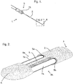
- a molecular exchange device (1) comprises a casing (2) made of HDPE, extending from a proximal end (3) to a distal end (4); and an anchoring unit (15) to hold the device (1) in position during use.
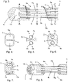
- the casing (2) supports two fluid passageways (7a, 7b) extending from the proximal end (3) to the distal end (4); a separator (6) extending along the length of the casing (2) separating the two fluid passageways; two aligned exchange apertures, between the proximal end (3) and the distal end (4) of the casing, exposing the fluid passageways (7a, 7b).
- the portion of the fluid passageways (7a, 7b) exposed by the opposed exchange apertures are porous.
- the casing (2) defines two internal lumens (5a, 5b) that extend within the casing from the proximal end (3) to the distal end (4).
- a separator (6) integral with the casing (2), extends along the central axis of the casing (2) defining the two lumens (5a, 5b) within the casing (2). It is also envisaged that the separator (6) is not integral with the casing (2), but firmly attached thereto.
- the lumens (5a, 5b) each hold a fluid passageway (7a, 7b) in the form of a tube.
- the tubes (7a, 7b) are suitable for fluid to travel within the passageway.
- the fluid may be supplied or drawn at the proximal end (3) of the tube (7a, 7b).
- the tubes are formed from a porous membrane that allows the selective exchange of molecules in one or both directions across the membrane. The level of porosity of the porous membrane will depend upon the intended use of the molecular exchange device (1).
- the tubes (7a, 7b) have a porosity that enables a specific molecule or composition to cross the membrane from the environment external to the tube (7a, 7b) into the tube (7a, 7b) and vice versa, for a particular use of the molecular exchange device (1).
- the casing (2) has aligning exchange apertures (9a, 9b) that each expose a tube (7a, 7b). It is also envisaged that the apertures (9a, 9b) are not aligned along the length of the casing (2). In this embodiment the entire circumference of the tube (7a, 7b) adjacent to the exchange aperture (9a, 9b) is exposed to the external environment, as shown in figure 5 .
- the tube (7a, 7b) is sealed to the casing (2) by, for example, glue and this arrangement holds the tube away from the surface of the separator (6), such that 100% or substantially 100% of the circumference of the tube (7a, 7b), including that adjacent to the exchange aperture, is exposed to the external environment.
- the distal end (4) of the casing (2) containing a flow chamber (10) that permits the passage of a fluid from one of the tubes (7a) to the other tube (7b). It is envisaged that fluid may flow in either direction in each tube (7a, 7b) and, as such, the flow chamber (10) permits the passage of fluid in both directions, i.e. from one tube (7a) to the other tube (7b) and vice versa.
- the external configuration of the flow chamber (10) is tapered, to allow easy insertion of the molecular exchange device (1) into a subject.
- the tubes (7a, 7b) extend into and terminate within the flow chamber (10).
- the tubes (7a, 7b) are sealed into the casing by, for example, heat treatment or glue, such as UV curing glue, cyanoacrylate, two-part epoxy resin and any other appropriate method, including mechanical means.
- the molecular exchange device (1) as shown in figure 7 , is further provided with a channel (11), extending from the proximal end (3) to the distal end (4) of the casing (2), that runs internally through separator (6).
- the tubes (7a, 7b) are profiled to accommodate the channel (11).
- the profile of the tubes (7a, 7b) allow the correct orientation of the tubes (7a, 7b) in the lumens (5a, 5b).
- the channel (11) provides a means to transport materials, such as a drug, into and out of the flow chamber, once the molecular exchange device (1) has been placed in the desired position within a subject.
- a sensor may be positioned on one or both of the ends of the tubes (7a, 7b), the sensor measuring, for example, a drug within the flow chamber (10).
- the rate of delivery of the drug into the device (1) can be altered in accordance with the concentration of the drug across the membrane.
- the rate of delivery of the drug can be controlled by changing the quantity of a drug introduced into the device. The higher the quantity of a drug passed into the device (1), the greater the delivery of the drug to the environment external to the device (1) when a concentration gradient that has been set up across the dialysis membrane.
- fluid may be passed into one of the tubes (7a, 7b) of the molecular exchange device (1).
- the fluid may be passed along the tube (7a), into the flow chamber, into the second tube (7b), along the second tube (7b) to the opening of the passageway at the proximal end (3) of the device (1). Due to the nature of the material of the casing (1), the fluid and any compositions in it will be maintained within the tube (7), except at the exchange apertures.
- the fluid carried in the respective tube (7a, 7b) will be exposed to the environment surrounding the molecular exchange device (1).
- molecules/compositions present in the tube (7a, 7b) may be supplied across the porous membrane into the environment external to the device (1) or molecules/compositions present in the external environment may be drawn across the porous membrane are into the tube (7a, 7b).
- the first tube (7a) may have the same properties (for example porosity) as the other tube (7b) and used for the same function.
- the first tube (7a) could be used to supply and/or absorb different molecules/compositions and, as such, have different properties.
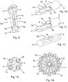
- the distal end (4) of the casing (2) may alternatively comprise a plug (12).
- the separator (6) has a flow aperture (13) to allow flow from one tube (7a) to the other tube (7b) and vice versa.
- a further example of the present disclosure comprises a casing (2) having an integral separator (6), extending from the proximal end (3) to the distal end (4) of the casing (2).
- a fluid passageway in the form of a tube extends within one of the lumens (5a) from the proximal end (3) to the distal end (4) of the casing, extending beyond the distal end of the casing, bends back on itself, and extends back into the second lumen (5b) from the distal end (4) to the proximal end (3) of the casing (2), providing a single uninterrupted tube (7a, 7b), anchored, at least, at the proximal end (3) of the casing (2). Therefore, fragmentation of the tubes (7a, 7b), in use, is prevented.
- the tube may also be bonded along the length of the casing (2) but only to retain its orientation rather than provide additional bonding.
- a further example of the disclosure is the same as that described with reference to figure 9 above, except that the tube at the distal end (4) of the casing is fully contained within the casing (2); the casing being in a similar confirmation as shown in figures 2 and 3 .
- the fluid may be passed along the first passageway (7a), through the distal end and along the second passageway (7b) to the opening of the passageway at the proximal end of the device (1). Again the fluid is exposed to the external environment at each exchange apertures along the casing, permitting selective exchange of molecules/compositions across the porous portion of the tubes (7a, 7b).
- the two tubes (7a, 7b) are arranged in two distinct lumens (5a, 5b).
- Each of the tubes (7a, 7b) has a concentric arrangement within the tube, such that fluid may flow along a internal tube and back along the external tube and vice versa. There is no fluid connection between the two fluid passagewayss (7a, 7b).
- Such an arrangement is suitable, for example, for use when one of the tubes (7a) provides a dialysis membrane and the other tube (7b) monitors the concentration levels of molecules/compositions in the external environment.
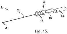
- molecule/compositions cross the porous portion of the tube (7b) from the external environment into the tube (7b) of the device (1), and travel along the tube (7b) to the proximal end (3) of the casing (2) and carried to an external device (14) for analysis, as shown in figure 15 .
- one tube provides two fluid passageways (7a, 7b).
- a further example of the disclosure as shown in figure 12 , comprises a device (1) in which the external walls of the casing (2) are arranged at the exchange aperture (9) to form a concave aperture (9a).
- a molecular exchange device (1) can be provided with a casing (2) having two or more of fluid passageways (7a, 7b, 7c, 7d), separated by a separator (6).
- the molecular exchange may be for analysis, dialysis, delivery etc.
- the device (1) has four fluid passageways (7a, 7b, 7c, 7d).
- the device (1) has twelve fluid passageways (7a, 7b, 7c, 7d etc.).
- FIG. 15 illustrates schematically an apparatus embodying the present invention.
- a molecular exchange device (1) is connected with an anchoring unit (15), such as a luer lock, and is in fluid communication, by means of tubing (16), with an external device (14).
- the external device (14) may analyse fluid received from the device (1), for instance to detect certain molecules/compositions or concentrations of molecule/compositions, or may supply molecule/compositions in a fluid for supply to the device (1), for instance maintaining concentrations of those compositions in the fluid passageways.
- a molecular exchange device (1) according to the present invention is preferably manufactured by injection moulding the casing (2) having a central separator (6) and plurality of exchange apertures (9) and then heat-sealing or crimping the distal end (4), either before or after insertion of the hollow tubes (7).
- the casing (2) could be formed as an extrusion process, with the walls of the casing (2) being removed to form the exchange apertures (9).
- the exchange apertures could be formed by treating the material of the casing (2) appropriately, as would be appreciated by those of skill in the art, to render the wall of the casing porous.
- the molecular exchange device of the present invention and one or more external devices can be used to analyse, measure or deliver industrial, chemical, fermentation and animal or plant compositions.
- the molecular exchange device may be used in industrial, chemical or fermentation processes and the human or animal body.
- the molecular exchange advice according to the present invention is intended to be used in the human or animal bodies including but not restricted to the circulatory system, insertion into blood vessels, lymphatic system, muscles, ear, mouth, tissue fat and internal organs.
Claims (14)
- Dispositif d'échange moléculaire (1) comprenant :un boîtier (2), s'étendant d'une extrémité proximale à une extrémité distale, supportant deux ou plus de deux passages de fluide (7a, 7b) s'étendant de l'extrémité proximale (3) à l'extrémité distale (4) ; le boîtier comprenant deux ou plus de deux orifices d'échange (9a, 9b) entre l'extrémité distale et l'extrémité proximale,dans lequel une partie de chacun des deux ou plus de deux passages de fluide (7a, 7b) exposée par l'orifice d'échange (9a, 9b) est poreuse, les deux ou plus de deux passages de fluide (7a, 7b) sont en communication fluidique l'un avec l'autre ; et l'extrémité distale du boîtier a la forme d'une pointe contenant une chambre d'écoulement (10) pour permettre l'écoulement d'une extrémité d'un des deux ou plus de deux passages de fluide dans l'extrémité de l'autre des deux ou plus de deux passages de fluide.
- Dispositif d'échange moléculaire selon la revendication 1, dans lequel un séparateur (6) s'étend le long du boîtier sur au moins une longueur de l'orifice d'échange, séparant les deux ou plus de deux passages de fluide.
- Dispositif d'échange moléculaire selon l'une quelconque des revendications 1 à 2, dans lequel le séparateur s'étend sensiblement le long de la longueur totale du boîtier, de l'extrémité distale à l'extrémité proximale, séparant les deux ou plus de deux passages de fluide.
- Dispositif d'échange moléculaire selon l'une quelconque des revendications 2 à 3, dans lequel le séparateur s'étend le long d'un axe central du boîtier ; de préférence deux passages de fluide sont agencés sur des côtés alignés du séparateur central, ou deux ou plus de deux passages de fluide sont agencés autour du séparateur central.
- Dispositif d'échange moléculaire selon l'une quelconque des revendications précédentes, dans lequel les deux ou plus de deux passages de fluide sont définis par le boîtier et/ou le séparateur, ou les deux ou plus de deux passages de fluide ne sont pas définis par le boîtier et/ou le séparateur ; de préférence chacun des deux ou plus de deux passages de fluide est un ou plusieurs tubes tenus dans le boîtier ; plus préférablement le ou les tubes sont une membrane poreuse.
- Dispositif d'échange moléculaire selon l'une quelconque des revendications 1 à 5, dans lequel la région poreuse du passage de fluide est une membrane poreuse liée avec le boîtier aux extrémités distale et proximale de l'orifice d'échange ; de préférence dans lequel la membrane poreuse est une membrane de dialyse.
- Dispositif d'échange moléculaire selon la revendication 5, dans lequel le ou les conduits ont une section transversale de forme circulaire ou non circulaire, de préférence, la section transversale a un côté droit et, plus préférablement, la section transversale est en forme de D.
- Dispositif d'échange moléculaire selon l'une quelconque des revendications précédentes, dans lequel l'orifice d'échange est une ouverture, de préférence formée en découpant une partie du boîtier ; ou l'orifice d'échange est une ouverture, de préférence formée en traitant le boîtier pour qu'une partie du boîtier soit poreuse.
- Dispositif d'échange moléculaire selon l'une quelconque des revendications précédentes, dans lequel les deux ou plus de deux passages de fluide (7a, 7b) ont des orifices d'échange alignés ou non alignés (9a, 9b), et/ou dans lequel plusieurs orifices d'échange exposent le même passage de fluide ; et/ou dans lequel les parties poreuses des orifices d'échange ont des porosités différentes ; et/ou dans lequel l'extrémité distale du dispositif comprend un bouchon (12) dans l'extrémité du boîtier ; et/ou dans lequel le séparateur s'étend jusqu'à l'extrémité distale du boîtier et contient un orifice de fluide pour permettre l'écoulement d'un passage de fluide à un autre passage de fluide ; et/ou selon l'une quelconque des revendications précédentes, et de préférence les extrémités des deux ou plus de deux passages de fluide s'étendent dans la chambre d'écoulement.
- Dispositif d'échange moléculaire selon la revendication 9, dans lequel la chambre d'écoulement a un agencement de capteurs afin, de préférence, de permettre une mesure spectrologique ; plus préférablement la mesure spectrologique est une mesure spectrophotométrique ; ou l'ensemble capteur est un réflecteur, un guide d'ondes, un conducteur, un capteur photoélectrique, électro-actif ou électrochimique.
- Dispositif d'échange moléculaire selon l'une quelconque des revendications précédentes, comprenant en outre un canal (11) allant de l'extrémité proximale du boîtier à l'extrémité distale du boîtier pour fournir des matériaux additionnels à l'intérieur et/ou à l'intérieur de l'extrémité distale du boîtier ; de préférence le canal fait partie intégrante du séparateur ; plus préférablement le canal est formé dans l'axe central du séparateur.
- Dispositif d'échange moléculaire selon la revendication 11, dans lequel le canal fournit un accès à/pour une sonde optique, sonique et/ou électrique.
- Dispositif d'échange moléculaire selon l'une quelconque des revendications précédentes, dans lequel l'extrémité proximale du boîtier est adaptée pour se fixer à un cathéter et/ou une canule ; et/ou l'extrémité proximale du boîtier est un agencement d'accouplement verrouillable et/ou un élément d'ancrage destiné à se connecter à un orifice invasif ; et/ou l'extrémité proximale du boîtier est adaptée pour se fixer à une pompe ; et/ou l'extrémité proximale du boîtier est adaptée pour se fixer à un dispositif externe (14).
- Système destiné à réguler la concentration d'une première substance dans un passage de fluide du dispositif d'échange moléculaire, le système comprenant le dispositif d'échange moléculaire selon l'une quelconque des revendications 1 à 13, un dispositif de régulation relié au dispositif d'échange moléculaire, dans lequel le dispositif de régulation mesure la concentration d'une deuxième substance dans un passage de fluide et régule l'alimentation de la première substance dans un passage de fluide, de préférence en réponse à la concentration mesurée ; et plus préférablement les première et deuxième substances peuvent être les mêmes ou différentes l'une de l'autre.
Applications Claiming Priority (2)
| Application Number | Priority Date | Filing Date | Title |
|---|---|---|---|
| GB0619157.1A GB2442209B (en) | 2006-09-28 | 2006-09-28 | Molecular exchange device |
| PCT/GB2007/003695 WO2008038015A2 (fr) | 2006-09-28 | 2007-09-28 | dispositif d'échange moléculaire |
Publications (2)
| Publication Number | Publication Date |
|---|---|
| EP2079369A2 EP2079369A2 (fr) | 2009-07-22 |
| EP2079369B1 true EP2079369B1 (fr) | 2019-09-25 |
Family
ID=37434851
Family Applications (1)
| Application Number | Title | Priority Date | Filing Date |
|---|---|---|---|
| EP07823956.3A Active EP2079369B1 (fr) | 2006-09-28 | 2007-09-28 | Dispositif d'échange moléculaire |
Country Status (14)
| Country | Link |
|---|---|
| US (1) | US8790586B2 (fr) |
| EP (1) | EP2079369B1 (fr) |
| JP (1) | JP5393464B2 (fr) |
| CN (2) | CN105997100A (fr) |
| AU (1) | AU2007301754B2 (fr) |
| CA (1) | CA2664134C (fr) |
| ES (1) | ES2761939T3 (fr) |
| GB (1) | GB2442209B (fr) |
| MX (1) | MX2009003367A (fr) |
| NO (1) | NO20091693L (fr) |
| RU (1) | RU2470590C2 (fr) |
| SG (1) | SG175561A1 (fr) |
| WO (1) | WO2008038015A2 (fr) |
| ZA (1) | ZA200902866B (fr) |
Families Citing this family (5)
| Publication number | Priority date | Publication date | Assignee | Title |
|---|---|---|---|---|
| EP2257215B1 (fr) * | 2008-01-30 | 2015-11-11 | Flowsion A/S | Sonde de microdialyse et procédé de fabrication de la sonde |
| SE539230C2 (en) * | 2015-09-04 | 2017-05-23 | Senzime Ab (Publ ) | Microdialysis device comprising attachment sheet |
| US11014047B2 (en) | 2015-12-08 | 2021-05-25 | The Regents Of The University Of Michigan | Microfabrication of a microdialysis probe with nanoporous membrane |
| USD816228S1 (en) | 2016-07-26 | 2018-04-24 | C. R. Bard, Inc. | Vascular access port stem |
| DE102016120699B3 (de) | 2016-10-28 | 2018-03-08 | Trace Analytics Gmbh | Sonde mit zwei Entnahmeöffnungen |
Family Cites Families (39)
| Publication number | Priority date | Publication date | Assignee | Title |
|---|---|---|---|---|
| DE1951659C3 (de) * | 1969-10-14 | 1979-08-16 | Kabel- Und Metallwerke Gutehoffnungshuette Ag, 3000 Hannover | Abstandwendel für koaxiale Rohrsysteme |
| US3981299A (en) * | 1971-03-15 | 1976-09-21 | Harry Elmer Murray | Urethral catheter |
| DE2734247C2 (de) * | 1977-07-29 | 1984-07-19 | Fresenius AG, 6380 Bad Homburg | Vorrichtung zur fortlaufenden chemischen Analyse im lebenden Körper |
| US4274417A (en) | 1978-09-22 | 1981-06-23 | National Research Development Corporation | Instruments for use in the measurement of gases in body fluids |
| GB2053719B (en) * | 1979-06-07 | 1983-04-20 | Medishield Corp Ltd | Probe for absorbed gas analysis |
| US4707268A (en) * | 1982-10-18 | 1987-11-17 | Baxter Travenol Laboratories, Inc. | Hollow fiber potted microfilter |
| SE434214B (sv) * | 1982-12-01 | 1984-07-16 | Carl Urban Ungerstedt | Dialysprob, avsedd for inforing i biologiska vevnader |
| JPS61206459A (ja) * | 1985-03-11 | 1986-09-12 | 株式会社日立製作所 | カテ−テル |
| US5156844A (en) * | 1987-11-17 | 1992-10-20 | Brown University Research Foundation | Neurological therapy system |
| US5021044A (en) | 1989-01-30 | 1991-06-04 | Advanced Cardiovascular Systems, Inc. | Catheter for even distribution of therapeutic fluids |
| FR2648353B1 (fr) * | 1989-06-16 | 1992-03-27 | Europhor Sa | Sonde de microdialyse |
| FR2655548A1 (fr) | 1989-12-11 | 1991-06-14 | Cleef Jean Francois Van | Catheter a parois non lisses, catheter a parois moulurees. |
| US5191900A (en) * | 1991-04-10 | 1993-03-09 | The Board Of Trustees Of The University Of Illinois | Dialysis probe |
| SG48792A1 (en) * | 1991-06-28 | 1998-05-18 | Univ Brown Res Found | Renewable neural implant device and method |
| DE4206096A1 (de) | 1992-02-27 | 1993-09-02 | Wolf Woco & Co Franz J | Koaxialrohr |
| GB9226147D0 (en) | 1992-12-15 | 1993-02-10 | Inst Of Neurology | Dialysis probes |
| SE512416C2 (sv) | 1993-10-12 | 2000-03-13 | Cma Microdialysis Ab | Sätt för uppsamling av små vätskeprovmängder, samt provbehållare för upptagning av små vätskemängder |
| SE502438C2 (sv) * | 1994-02-04 | 1995-10-16 | Cma Microdialysis Holding Ab | Förstärkt mikrodialysprob |
| US5441481A (en) * | 1994-05-27 | 1995-08-15 | Mishra; Pravin | Microdialysis probes and methods of use |
| CN2281761Y (zh) * | 1996-07-09 | 1998-05-20 | 郭述苏 | 微透析探针 |
| DE19714572C1 (de) * | 1997-04-09 | 1998-06-25 | Haindl Hans | Katheter zur Messung chemischer Parameter, insbesondere zum Einführen in biologisches Gewebe, Flüssigkeiten oder dergleichen |
| US6106776A (en) | 1997-04-11 | 2000-08-22 | University Of Pittsburgh | Membrane apparatus with enhanced mass transfer via active mixing |
| JP3372862B2 (ja) * | 1998-03-25 | 2003-02-04 | 株式会社日立製作所 | 生体液の質量分析装置 |
| GB2341119B (en) * | 1998-08-18 | 2001-11-14 | Connell Mark Thomas O | Dialysis probe |
| JP3229599B2 (ja) | 1999-06-01 | 2001-11-19 | ホスパル株式会社 | 血液浄化装置とそれを使用した人工腎臓 |
| SE514552C2 (sv) | 1999-07-14 | 2001-03-12 | Cma Microdialysis Ab | Microdialyssond |
| SE9902695L (sv) * | 1999-07-14 | 2001-01-15 | Cma Microdialysis Ab | Förbättrad sond |
| US6346090B1 (en) * | 1999-07-23 | 2002-02-12 | Jan Liska | Microdialysis catheter for insertion into a blood vessel |
| AU778076B2 (en) | 1999-09-17 | 2004-11-11 | Tyco Healthcare Group Lp | Mechanical pump for removal of fragmented matter and methods of manufacture and use |
| US6299593B1 (en) * | 2000-03-03 | 2001-10-09 | Akio Wakabayashi | Double and multiple lumen chest drainage tube |
| SE0104469D0 (sv) * | 2001-12-28 | 2001-12-28 | Microbiotech Se Ab | Microdialysis probe and assembly |
| US6811542B2 (en) * | 2002-06-24 | 2004-11-02 | Jan Liska | Microdialysis probe and catheter arrangement |
| DE10246207B4 (de) | 2002-10-04 | 2008-04-03 | Disetronic Licensing Ag | Mikrodialysesonde mit spiralförmiger Leitung |
| DE10247023B4 (de) * | 2002-10-09 | 2006-07-20 | Disetronic Licensing Ag | Mikrodialysesonde und Verfahren zu deren Herstellung |
| RU31725U1 (ru) * | 2003-04-07 | 2003-08-27 | Рябинин Вячеслав Евгеньевич | Аппарат "искусственная печень" |
| US7241283B2 (en) * | 2003-04-25 | 2007-07-10 | Ad-Tech Medical Instrument Corp. | Method for intracranial catheter treatment of brain tissue |
| AU2004238338C1 (en) * | 2003-05-12 | 2011-01-20 | Avent, Inc. | Catheter for uniform delivery of medication |
| CN100352524C (zh) * | 2005-03-04 | 2007-12-05 | 浙江大学 | 一种带有透析膜保护的微透析装置 |
| US20070095756A1 (en) * | 2005-10-31 | 2007-05-03 | General Electric Company | System and method for removal of contaminants from feed solution |
-
2006
- 2006-09-28 GB GB0619157.1A patent/GB2442209B/en active Active
-
2007
- 2007-09-28 SG SG2011070075A patent/SG175561A1/en unknown
- 2007-09-28 ES ES07823956T patent/ES2761939T3/es active Active
- 2007-09-28 JP JP2009529765A patent/JP5393464B2/ja active Active
- 2007-09-28 EP EP07823956.3A patent/EP2079369B1/fr active Active
- 2007-09-28 MX MX2009003367A patent/MX2009003367A/es active IP Right Grant
- 2007-09-28 CN CN201510457362.8A patent/CN105997100A/zh active Pending
- 2007-09-28 AU AU2007301754A patent/AU2007301754B2/en not_active Ceased
- 2007-09-28 RU RU2009115246/14A patent/RU2470590C2/ru not_active IP Right Cessation
- 2007-09-28 CN CNA2007800437948A patent/CN101563036A/zh active Pending
- 2007-09-28 CA CA2664134A patent/CA2664134C/fr not_active Expired - Fee Related
- 2007-09-28 WO PCT/GB2007/003695 patent/WO2008038015A2/fr active Application Filing
- 2007-09-28 US US12/443,449 patent/US8790586B2/en active Active
-
2009
- 2009-04-24 ZA ZA2009/02866A patent/ZA200902866B/en unknown
- 2009-04-28 NO NO20091693A patent/NO20091693L/no not_active Application Discontinuation
Non-Patent Citations (1)
| Title |
|---|
| None * |
Also Published As
| Publication number | Publication date |
|---|---|
| EP2079369A2 (fr) | 2009-07-22 |
| CA2664134C (fr) | 2017-11-28 |
| RU2009115246A (ru) | 2010-11-10 |
| CN101563036A (zh) | 2009-10-21 |
| RU2470590C2 (ru) | 2012-12-27 |
| AU2007301754B2 (en) | 2013-05-16 |
| US20100016779A1 (en) | 2010-01-21 |
| GB2442209A (en) | 2008-04-02 |
| WO2008038015A2 (fr) | 2008-04-03 |
| MX2009003367A (es) | 2009-08-31 |
| US8790586B2 (en) | 2014-07-29 |
| SG175561A1 (en) | 2011-11-28 |
| JP2010504787A (ja) | 2010-02-18 |
| NO20091693L (no) | 2009-06-23 |
| JP5393464B2 (ja) | 2014-01-22 |
| AU2007301754A1 (en) | 2008-04-03 |
| GB2442209B (en) | 2012-01-18 |
| ZA200902866B (en) | 2012-09-26 |
| WO2008038015A3 (fr) | 2008-07-03 |
| GB0619157D0 (en) | 2006-11-08 |
| CN105997100A (zh) | 2016-10-12 |
| CA2664134A1 (fr) | 2008-04-03 |
| ES2761939T3 (es) | 2020-05-21 |
Similar Documents
| Publication | Publication Date | Title |
|---|---|---|
| US5441481A (en) | Microdialysis probes and methods of use | |
| US6537243B1 (en) | Device and method for obtaining interstitial fluid from a patient for diagnostic tests | |
| EP2023994B1 (fr) | Cathéter à fente de forme oblongue | |
| EP2079369B1 (fr) | Dispositif d'échange moléculaire | |
| CA2737634C (fr) | Catheter a base de filament | |
| WO2009049823A1 (fr) | Cathéter et procédés pour l'utiliser et le fabriquer | |
| US20080234563A1 (en) | Device for and Method of Delivery and Removal of Substances in and From a Tissue or Vessel | |
| US20170225125A1 (en) | Molecular exchange device | |
| EP2254639B1 (fr) | Dispositif d'échange moléculaire | |
| EP1105045B1 (fr) | Sonde pour dialyses |
Legal Events
| Date | Code | Title | Description |
|---|---|---|---|
| PUAI | Public reference made under article 153(3) epc to a published international application that has entered the european phase |
Free format text: ORIGINAL CODE: 0009012 |
|
| 17P | Request for examination filed |
Effective date: 20090428 |
|
| AK | Designated contracting states |
Kind code of ref document: A2 Designated state(s): AT BE BG CH CY CZ DE DK EE ES FI FR GB GR HU IE IS IT LI LT LU LV MC MT NL PL PT RO SE SI SK TR |
|
| AX | Request for extension of the european patent |
Extension state: HR RS |
|
| RAP1 | Party data changed (applicant data changed or rights of an application transferred) |
Owner name: BLOCK, STEWART Owner name: PROBE SCIENTIFIC LIMITED |
|
| RAP1 | Party data changed (applicant data changed or rights of an application transferred) |
Owner name: PROBE SCIENTIFIC LIMITED |
|
| 17Q | First examination report despatched |
Effective date: 20120522 |
|
| RAX | Requested extension states of the european patent have changed |
Extension state: RS Payment date: 20090428 Extension state: HR Payment date: 20090428 |
|
| STAA | Information on the status of an ep patent application or granted ep patent |
Free format text: STATUS: EXAMINATION IS IN PROGRESS |
|
| GRAP | Despatch of communication of intention to grant a patent |
Free format text: ORIGINAL CODE: EPIDOSNIGR1 |
|
| STAA | Information on the status of an ep patent application or granted ep patent |
Free format text: STATUS: GRANT OF PATENT IS INTENDED |
|
| INTG | Intention to grant announced |
Effective date: 20180801 |
|
| GRAJ | Information related to disapproval of communication of intention to grant by the applicant or resumption of examination proceedings by the epo deleted |
Free format text: ORIGINAL CODE: EPIDOSDIGR1 |
|
| STAA | Information on the status of an ep patent application or granted ep patent |
Free format text: STATUS: EXAMINATION IS IN PROGRESS |
|
| GRAP | Despatch of communication of intention to grant a patent |
Free format text: ORIGINAL CODE: EPIDOSNIGR1 |
|
| STAA | Information on the status of an ep patent application or granted ep patent |
Free format text: STATUS: GRANT OF PATENT IS INTENDED |
|
| INTC | Intention to grant announced (deleted) | ||
| INTG | Intention to grant announced |
Effective date: 20190411 |
|
| GRAS | Grant fee paid |
Free format text: ORIGINAL CODE: EPIDOSNIGR3 |
|
| GRAA | (expected) grant |
Free format text: ORIGINAL CODE: 0009210 |
|
| STAA | Information on the status of an ep patent application or granted ep patent |
Free format text: STATUS: THE PATENT HAS BEEN GRANTED |
|
| AK | Designated contracting states |
Kind code of ref document: B1 Designated state(s): AT BE BG CH CY CZ DE DK EE ES FI FR GR HU IE IS IT LI LT LU LV MC MT NL PL PT RO SE SI SK TR |
|
| AX | Request for extension of the european patent |
Extension state: HR RS |
|
| RBV | Designated contracting states (corrected) |
Designated state(s): AT BE BG CH CY CZ DE DK EE ES FI FR GR HU IE IS IT LI LT LU LV MC MT NL PL PT RO SE SI SK TR |
|
| REG | Reference to a national code |
Ref country code: CH Ref legal event code: EP |
|
| REG | Reference to a national code |
Ref country code: AT Ref legal event code: REF Ref document number: 1183025 Country of ref document: AT Kind code of ref document: T Effective date: 20191015 |
|
| REG | Reference to a national code |
Ref country code: IE Ref legal event code: FG4D |
|
| REG | Reference to a national code |
Ref country code: DE Ref legal event code: R096 Ref document number: 602007059265 Country of ref document: DE |
|
| REG | Reference to a national code |
Ref country code: NL Ref legal event code: MP Effective date: 20190925 |
|
| PG25 | Lapsed in a contracting state [announced via postgrant information from national office to epo] |
Ref country code: BG Free format text: LAPSE BECAUSE OF FAILURE TO SUBMIT A TRANSLATION OF THE DESCRIPTION OR TO PAY THE FEE WITHIN THE PRESCRIBED TIME-LIMIT Effective date: 20191225 Ref country code: LT Free format text: LAPSE BECAUSE OF FAILURE TO SUBMIT A TRANSLATION OF THE DESCRIPTION OR TO PAY THE FEE WITHIN THE PRESCRIBED TIME-LIMIT Effective date: 20190925 Ref country code: FI Free format text: LAPSE BECAUSE OF FAILURE TO SUBMIT A TRANSLATION OF THE DESCRIPTION OR TO PAY THE FEE WITHIN THE PRESCRIBED TIME-LIMIT Effective date: 20190925 Ref country code: SE Free format text: LAPSE BECAUSE OF FAILURE TO SUBMIT A TRANSLATION OF THE DESCRIPTION OR TO PAY THE FEE WITHIN THE PRESCRIBED TIME-LIMIT Effective date: 20190925 |
|
| REG | Reference to a national code |
Ref country code: LT Ref legal event code: MG4D |
|
| PG25 | Lapsed in a contracting state [announced via postgrant information from national office to epo] |
Ref country code: GR Free format text: LAPSE BECAUSE OF FAILURE TO SUBMIT A TRANSLATION OF THE DESCRIPTION OR TO PAY THE FEE WITHIN THE PRESCRIBED TIME-LIMIT Effective date: 20191226 Ref country code: LV Free format text: LAPSE BECAUSE OF FAILURE TO SUBMIT A TRANSLATION OF THE DESCRIPTION OR TO PAY THE FEE WITHIN THE PRESCRIBED TIME-LIMIT Effective date: 20190925 |
|
| REG | Reference to a national code |
Ref country code: AT Ref legal event code: MK05 Ref document number: 1183025 Country of ref document: AT Kind code of ref document: T Effective date: 20190925 |
|
| PG25 | Lapsed in a contracting state [announced via postgrant information from national office to epo] |
Ref country code: RO Free format text: LAPSE BECAUSE OF FAILURE TO SUBMIT A TRANSLATION OF THE DESCRIPTION OR TO PAY THE FEE WITHIN THE PRESCRIBED TIME-LIMIT Effective date: 20190925 Ref country code: AT Free format text: LAPSE BECAUSE OF FAILURE TO SUBMIT A TRANSLATION OF THE DESCRIPTION OR TO PAY THE FEE WITHIN THE PRESCRIBED TIME-LIMIT Effective date: 20190925 Ref country code: NL Free format text: LAPSE BECAUSE OF FAILURE TO SUBMIT A TRANSLATION OF THE DESCRIPTION OR TO PAY THE FEE WITHIN THE PRESCRIBED TIME-LIMIT Effective date: 20190925 Ref country code: PL Free format text: LAPSE BECAUSE OF FAILURE TO SUBMIT A TRANSLATION OF THE DESCRIPTION OR TO PAY THE FEE WITHIN THE PRESCRIBED TIME-LIMIT Effective date: 20190925 Ref country code: EE Free format text: LAPSE BECAUSE OF FAILURE TO SUBMIT A TRANSLATION OF THE DESCRIPTION OR TO PAY THE FEE WITHIN THE PRESCRIBED TIME-LIMIT Effective date: 20190925 Ref country code: PT Free format text: LAPSE BECAUSE OF FAILURE TO SUBMIT A TRANSLATION OF THE DESCRIPTION OR TO PAY THE FEE WITHIN THE PRESCRIBED TIME-LIMIT Effective date: 20200127 |
|
| REG | Reference to a national code |
Ref country code: ES Ref legal event code: FG2A Ref document number: 2761939 Country of ref document: ES Kind code of ref document: T3 Effective date: 20200521 |
|
| PG25 | Lapsed in a contracting state [announced via postgrant information from national office to epo] |
Ref country code: IS Free format text: LAPSE BECAUSE OF FAILURE TO SUBMIT A TRANSLATION OF THE DESCRIPTION OR TO PAY THE FEE WITHIN THE PRESCRIBED TIME-LIMIT Effective date: 20200224 Ref country code: CZ Free format text: LAPSE BECAUSE OF FAILURE TO SUBMIT A TRANSLATION OF THE DESCRIPTION OR TO PAY THE FEE WITHIN THE PRESCRIBED TIME-LIMIT Effective date: 20190925 Ref country code: SK Free format text: LAPSE BECAUSE OF FAILURE TO SUBMIT A TRANSLATION OF THE DESCRIPTION OR TO PAY THE FEE WITHIN THE PRESCRIBED TIME-LIMIT Effective date: 20190925 |
|
| REG | Reference to a national code |
Ref country code: CH Ref legal event code: PL |
|
| REG | Reference to a national code |
Ref country code: DE Ref legal event code: R097 Ref document number: 602007059265 Country of ref document: DE |
|
| RAP2 | Party data changed (patent owner data changed or rights of a patent transferred) |
Owner name: CORNEL MEDICAL LIMITED |
|
| PG2D | Information on lapse in contracting state deleted |
Ref country code: IS |
|
| PG25 | Lapsed in a contracting state [announced via postgrant information from national office to epo] |
Ref country code: DK Free format text: LAPSE BECAUSE OF FAILURE TO SUBMIT A TRANSLATION OF THE DESCRIPTION OR TO PAY THE FEE WITHIN THE PRESCRIBED TIME-LIMIT Effective date: 20190925 Ref country code: LI Free format text: LAPSE BECAUSE OF NON-PAYMENT OF DUE FEES Effective date: 20190930 Ref country code: IE Free format text: LAPSE BECAUSE OF NON-PAYMENT OF DUE FEES Effective date: 20190928 Ref country code: CH Free format text: LAPSE BECAUSE OF NON-PAYMENT OF DUE FEES Effective date: 20190930 Ref country code: LU Free format text: LAPSE BECAUSE OF NON-PAYMENT OF DUE FEES Effective date: 20190928 Ref country code: IS Free format text: LAPSE BECAUSE OF FAILURE TO SUBMIT A TRANSLATION OF THE DESCRIPTION OR TO PAY THE FEE WITHIN THE PRESCRIBED TIME-LIMIT Effective date: 20200126 |
|
| PLBE | No opposition filed within time limit |
Free format text: ORIGINAL CODE: 0009261 |
|
| STAA | Information on the status of an ep patent application or granted ep patent |
Free format text: STATUS: NO OPPOSITION FILED WITHIN TIME LIMIT |
|
| REG | Reference to a national code |
Ref country code: BE Ref legal event code: MM Effective date: 20190930 |
|
| PG25 | Lapsed in a contracting state [announced via postgrant information from national office to epo] |
Ref country code: BE Free format text: LAPSE BECAUSE OF NON-PAYMENT OF DUE FEES Effective date: 20190930 Ref country code: MC Free format text: LAPSE BECAUSE OF FAILURE TO SUBMIT A TRANSLATION OF THE DESCRIPTION OR TO PAY THE FEE WITHIN THE PRESCRIBED TIME-LIMIT Effective date: 20190925 |
|
| 26N | No opposition filed |
Effective date: 20200626 |
|
| REG | Reference to a national code |
Ref country code: DE Ref legal event code: R082 Ref document number: 602007059265 Country of ref document: DE Representative=s name: BOEHMERT & BOEHMERT ANWALTSPARTNERSCHAFT MBB -, DE Ref country code: DE Ref legal event code: R081 Ref document number: 602007059265 Country of ref document: DE Owner name: CORNEL MEDICAL LIMITED, GB Free format text: FORMER OWNER: PROBE SCIENTIFIC LTD., COVENTRY, GB |
|
| PG25 | Lapsed in a contracting state [announced via postgrant information from national office to epo] |
Ref country code: SI Free format text: LAPSE BECAUSE OF FAILURE TO SUBMIT A TRANSLATION OF THE DESCRIPTION OR TO PAY THE FEE WITHIN THE PRESCRIBED TIME-LIMIT Effective date: 20190925 |
|
| PG25 | Lapsed in a contracting state [announced via postgrant information from national office to epo] |
Ref country code: CY Free format text: LAPSE BECAUSE OF FAILURE TO SUBMIT A TRANSLATION OF THE DESCRIPTION OR TO PAY THE FEE WITHIN THE PRESCRIBED TIME-LIMIT Effective date: 20190925 |
|
| PG25 | Lapsed in a contracting state [announced via postgrant information from national office to epo] |
Ref country code: HU Free format text: LAPSE BECAUSE OF FAILURE TO SUBMIT A TRANSLATION OF THE DESCRIPTION OR TO PAY THE FEE WITHIN THE PRESCRIBED TIME-LIMIT; INVALID AB INITIO Effective date: 20070928 Ref country code: MT Free format text: LAPSE BECAUSE OF FAILURE TO SUBMIT A TRANSLATION OF THE DESCRIPTION OR TO PAY THE FEE WITHIN THE PRESCRIBED TIME-LIMIT Effective date: 20190925 |
|
| PG25 | Lapsed in a contracting state [announced via postgrant information from national office to epo] |
Ref country code: TR Free format text: LAPSE BECAUSE OF FAILURE TO SUBMIT A TRANSLATION OF THE DESCRIPTION OR TO PAY THE FEE WITHIN THE PRESCRIBED TIME-LIMIT Effective date: 20190925 |
|
| P01 | Opt-out of the competence of the unified patent court (upc) registered |
Effective date: 20230602 |
|
| P02 | Opt-out of the competence of the unified patent court (upc) changed |
Effective date: 20230616 |
|
| PGFP | Annual fee paid to national office [announced via postgrant information from national office to epo] |
Ref country code: IT Payment date: 20230913 Year of fee payment: 17 |
|
| PGFP | Annual fee paid to national office [announced via postgrant information from national office to epo] |
Ref country code: FR Payment date: 20230911 Year of fee payment: 17 Ref country code: DE Payment date: 20230906 Year of fee payment: 17 |
|
| PGFP | Annual fee paid to national office [announced via postgrant information from national office to epo] |
Ref country code: ES Payment date: 20231009 Year of fee payment: 17 |