EP2079204A1 - Transport de paquets client agrégés - Google Patents
Transport de paquets client agrégés Download PDFInfo
- Publication number
- EP2079204A1 EP2079204A1 EP08155314A EP08155314A EP2079204A1 EP 2079204 A1 EP2079204 A1 EP 2079204A1 EP 08155314 A EP08155314 A EP 08155314A EP 08155314 A EP08155314 A EP 08155314A EP 2079204 A1 EP2079204 A1 EP 2079204A1
- Authority
- EP
- European Patent Office
- Prior art keywords
- packets
- container
- packet
- network
- timing
- Prior art date
- Legal status (The legal status is an assumption and is not a legal conclusion. Google has not performed a legal analysis and makes no representation as to the accuracy of the status listed.)
- Granted
Links
- 238000000034 method Methods 0.000 claims abstract description 48
- 230000005540 biological transmission Effects 0.000 claims abstract description 25
- 239000000872 buffer Substances 0.000 claims description 45
- 238000013507 mapping Methods 0.000 claims description 9
- 230000001419 dependent effect Effects 0.000 claims description 8
- 238000009432 framing Methods 0.000 claims description 5
- 238000012544 monitoring process Methods 0.000 claims 3
- 238000004220 aggregation Methods 0.000 description 29
- 230000002776 aggregation Effects 0.000 description 21
- 238000009825 accumulation Methods 0.000 description 11
- 238000012545 processing Methods 0.000 description 11
- 230000003287 optical effect Effects 0.000 description 9
- 238000005538 encapsulation Methods 0.000 description 8
- 239000000835 fiber Substances 0.000 description 8
- 230000008569 process Effects 0.000 description 7
- 230000001360 synchronised effect Effects 0.000 description 7
- 230000002123 temporal effect Effects 0.000 description 6
- 230000004931 aggregating effect Effects 0.000 description 3
- 230000008901 benefit Effects 0.000 description 3
- 230000008859 change Effects 0.000 description 2
- 238000004891 communication Methods 0.000 description 2
- 238000005516 engineering process Methods 0.000 description 2
- 238000012986 modification Methods 0.000 description 2
- 230000004048 modification Effects 0.000 description 2
- 230000008447 perception Effects 0.000 description 2
- 238000011160 research Methods 0.000 description 2
- 238000007493 shaping process Methods 0.000 description 2
- 239000006163 transport media Substances 0.000 description 2
- XUIMIQQOPSSXEZ-UHFFFAOYSA-N Silicon Chemical compound [Si] XUIMIQQOPSSXEZ-UHFFFAOYSA-N 0.000 description 1
- 238000013459 approach Methods 0.000 description 1
- 230000007812 deficiency Effects 0.000 description 1
- 230000001934 delay Effects 0.000 description 1
- 239000000945 filler Substances 0.000 description 1
- 238000003780 insertion Methods 0.000 description 1
- 230000037431 insertion Effects 0.000 description 1
- 230000007774 longterm Effects 0.000 description 1
- 230000000116 mitigating effect Effects 0.000 description 1
- 230000006855 networking Effects 0.000 description 1
- 230000005693 optoelectronics Effects 0.000 description 1
- 230000009467 reduction Effects 0.000 description 1
- 229910052710 silicon Inorganic materials 0.000 description 1
- 239000010703 silicon Substances 0.000 description 1
- 238000010025 steaming Methods 0.000 description 1
Images

Classifications
-
- H—ELECTRICITY
- H04—ELECTRIC COMMUNICATION TECHNIQUE
- H04L—TRANSMISSION OF DIGITAL INFORMATION, e.g. TELEGRAPHIC COMMUNICATION
- H04L47/00—Traffic control in data switching networks
- H04L47/10—Flow control; Congestion control
-
- H—ELECTRICITY
- H04—ELECTRIC COMMUNICATION TECHNIQUE
- H04J—MULTIPLEX COMMUNICATION
- H04J3/00—Time-division multiplex systems
- H04J3/16—Time-division multiplex systems in which the time allocation to individual channels within a transmission cycle is variable, e.g. to accommodate varying complexity of signals, to vary number of channels transmitted
- H04J3/1605—Fixed allocated frame structures
- H04J3/1611—Synchronous digital hierarchy [SDH] or SONET
- H04J3/1617—Synchronous digital hierarchy [SDH] or SONET carrying packets or ATM cells
-
- H—ELECTRICITY
- H04—ELECTRIC COMMUNICATION TECHNIQUE
- H04L—TRANSMISSION OF DIGITAL INFORMATION, e.g. TELEGRAPHIC COMMUNICATION
- H04L47/00—Traffic control in data switching networks
- H04L47/10—Flow control; Congestion control
- H04L47/28—Flow control; Congestion control in relation to timing considerations
-
- H—ELECTRICITY
- H04—ELECTRIC COMMUNICATION TECHNIQUE
- H04L—TRANSMISSION OF DIGITAL INFORMATION, e.g. TELEGRAPHIC COMMUNICATION
- H04L47/00—Traffic control in data switching networks
- H04L47/50—Queue scheduling
-
- H—ELECTRICITY
- H04—ELECTRIC COMMUNICATION TECHNIQUE
- H04L—TRANSMISSION OF DIGITAL INFORMATION, e.g. TELEGRAPHIC COMMUNICATION
- H04L47/00—Traffic control in data switching networks
- H04L47/50—Queue scheduling
- H04L47/56—Queue scheduling implementing delay-aware scheduling
-
- H—ELECTRICITY
- H04—ELECTRIC COMMUNICATION TECHNIQUE
- H04L—TRANSMISSION OF DIGITAL INFORMATION, e.g. TELEGRAPHIC COMMUNICATION
- H04L47/00—Traffic control in data switching networks
- H04L47/50—Queue scheduling
- H04L47/62—Queue scheduling characterised by scheduling criteria
- H04L47/625—Queue scheduling characterised by scheduling criteria for service slots or service orders
- H04L47/627—Queue scheduling characterised by scheduling criteria for service slots or service orders policing
-
- H—ELECTRICITY
- H04—ELECTRIC COMMUNICATION TECHNIQUE
- H04J—MULTIPLEX COMMUNICATION
- H04J2203/00—Aspects of optical multiplex systems other than those covered by H04J14/05 and H04J14/07
- H04J2203/0001—Provisions for broadband connections in integrated services digital network using frames of the Optical Transport Network [OTN] or using synchronous transfer mode [STM], e.g. SONET, SDH
- H04J2203/0089—Multiplexing, e.g. coding, scrambling, SONET
-
- H—ELECTRICITY
- H04—ELECTRIC COMMUNICATION TECHNIQUE
- H04L—TRANSMISSION OF DIGITAL INFORMATION, e.g. TELEGRAPHIC COMMUNICATION
- H04L12/00—Data switching networks
- H04L12/54—Store-and-forward switching systems
- H04L12/56—Packet switching systems
- H04L12/5601—Transfer mode dependent, e.g. ATM
- H04L2012/5638—Services, e.g. multimedia, GOS, QOS
- H04L2012/5646—Cell characteristics, e.g. loss, delay, jitter, sequence integrity
- H04L2012/5649—Cell delay or jitter
-
- H—ELECTRICITY
- H04—ELECTRIC COMMUNICATION TECHNIQUE
- H04L—TRANSMISSION OF DIGITAL INFORMATION, e.g. TELEGRAPHIC COMMUNICATION
- H04L12/00—Data switching networks
- H04L12/54—Store-and-forward switching systems
- H04L12/56—Packet switching systems
- H04L12/5601—Transfer mode dependent, e.g. ATM
- H04L2012/5672—Multiplexing, e.g. coding, scrambling
- H04L2012/5674—Synchronisation, timing recovery or alignment
-
- H—ELECTRICITY
- H04—ELECTRIC COMMUNICATION TECHNIQUE
- H04L—TRANSMISSION OF DIGITAL INFORMATION, e.g. TELEGRAPHIC COMMUNICATION
- H04L12/00—Data switching networks
- H04L12/54—Store-and-forward switching systems
- H04L12/56—Packet switching systems
- H04L12/5601—Transfer mode dependent, e.g. ATM
- H04L2012/5678—Traffic aspects, e.g. arbitration, load balancing, smoothing, buffer management
- H04L2012/5679—Arbitration or scheduling
Definitions
- the invention relates to optical communication, in particular to a method of transmitting aggregated packets of one or more client signals via a packet transport network. Further, the invention relates to network elements for such packet transport network and to a packet transport network as such.
- Packets e.g. Ethernet packets
- the packet size is dimensioned to produce forwarding delays below the human temporal perception horizon.
- an Ethernet packet having a size of 1000 bytes takes 125 ms to be filled by voice call data having a data rate of 64 kbit/s, thereby producing a forwarding delay in the range of 125 ms.
- the additional packet-size dependent forwarding delay of packets is lower due to the speed-up from application data rate to core data rate.
- applications in particular applications with high data rate as video streaming applications having e.g. a data rate of 10 Mbit/s
- the fiber propagation delay of a span of 1000 km in a core network is in the range of 5 ms (independent of the packet size)
- the packet-size dependent forwarding delay of a packet having a size of 1000 bytes is as low as 1 ⁇ s, much lower than all other delay contributions.
- the overall additional forwarding delay in the core network is not dominated by the small packet-size dependent forwarding delay in the core network but mostly determined by other delay contributions.
- the small packet-size dependent forwarding delay in the core network would allow also larger packet sizes. However, as discussed above, typically the packet size is determined by the needs of the user application.
- Protocol packets may have even smaller packet sizes.
- TCP transmission control protocol
- ACK transmission control protocol
- This packet is used for acknowledging receipt of a packet in TCP and cannot be avoided in the existing Internet practice.
- each client packet may be separately encapsulated for transmission via the core network by the use of 1:1 encapsulation techniques like T-MPLS (Transport Multiprotocol Label Switching), PBB (Provider Backbone Bridge) or MAC-in-MAC, i.e. one Ethernet packet may be encapsulated in another Ethernet packet.
- T-MPLS Transport Multiprotocol Label Switching
- PBB Provider Backbone Bridge
- MAC-in-MAC i.e. one Ethernet packet may be encapsulated in another Ethernet packet.
- the encapsulated packet is opaque, i.e. not visible for the core network.
- the immutable packet size as determined by the user application is much too small for efficient transport of the same packet (or 1:1 encapsulated in another packet) in the core network since the header of each packet is processed in the core network.
- the packet processing capabilities of the core network elements have to be designed to be sufficient even in the worst case of maximum load and smallest packet size. Such scenario is unlikely to happen but cannot be safely excluded.
- core network line cards for 10 Gbit/s, 100 Gbit/s and above, e.g. for 100 Gbit/s Ethernet the header processing of the packets is the most power and silicon area consuming task.
- a well known approach for reducing the effort of header processing is the aggregation of smaller size packets into larger size containers, e.g. in optical burst switching (OBS) burstification of packets into larger containers (also called burst or frames) is used.
- OBS optical burst switching
- packets with the same destination are accumulated and aggregated into a container which in turn is moved as an opaque entity through the core network. Only at the respective network egress node, the container is unloaded and the contained packets are released to the client network.
- OBS the aggregation of packets into a container is necessary because of the low switching speed of optical devices. Without aggregation, the optical devices would have to be switched packet-wise which is not possible.
- electronic or opto-electronic switching the concept of accumulating packets and aggregating the accumulated packets into a container can be also reused for a reduction of the packet count per second in core switches.
- the timing of packet flows is a crucial parameter.
- the packet flow is naturally shaped by the originating network.
- the temporal distance between packets ensures that the transmission does overload neither the originating network nor the receiving network.
- the core network should preserve the timing of the packet flow, independently of the load by other traffic and without explicit knowledge of the individual flows. This is ensured by using queuing and scheduling schemes like Weighted Fair Queuing (WFQ) or Weighted Round Robin (WRR).
- WFQ Weighted Fair Queuing
- WRR Weighted Round Robin
- the fine grained packets of the client signals are typically encapsulated into larger transport containers, e.g. in the case of SDH (Synchronous Digital Hierarchy as defined in ITU-T G.701), SONET (Synchronous Optical Networking as defined in GR-253-CORE from Telcordia) or OTN (Optical Transport Network as defined in ITU-T G.709). All these transport protocols have in common that the container is a continuously moving TDM (time-division multiplexing) entity (synchronous traffic), i.e. containers are continuously generated and transmitted according to the data rate of the transport protocol, irrespective of the containers' load.
- TDM time-division multiplexing
- the client packets are mapped into the containers on the fly.
- the containers are padded by idle patterns as necessary.
- the relative timing of packets to each other does not change from an ingress node of such high speed network to an egress node of such network.
- Burst switched network are based on the concept of OBS.
- smaller packets of one or more client signals are aggregated into a larger burst which is to be transmitted to a specific egress node.
- the optical burst switches of the network are switched to forward the individual burst from the ingress node of the network to the respective egress node.
- the frames are switched inside the nodes of the network as separate entities, while the transmission links between the nodes keep the continuous, synchronous transmission pursuant to G.709.
- the client interface signals are aggregated into an adapted G.709 frame format by a frame aggregation unit.
- the frames are individually switched into the synchronous transport stream, i.e. frames are not periodically switched into the high speed transport stream with a fixed period.
- a larger size container i.e. a burst in case of a burst switched network, and a frame in case of a frame switched network
- client packets which normally waits until completion before being transmitted.
- completion of the container depends on the actual traffic load. Idle pattern between packets, e.g. in case of low traffic load, are generally not used.
- the client packets are encapsulated in the container one after another, regardless of the relative timing at the ingress node. Filling pattern may occur only at the end of the container. At the egress node, the encapsulated packets in the container are unloaded and released to the access network (or metro network).
- the client packets may be lumped together in bursts. This results in a high burden on the downstream network buffers.
- a high burstiness of the packet flow at the egress node may easily occur. Such high burstiness did not exist when the packets entered the ingress node.
- the method should overcome the problem of high burstiness of the flow at the egress node as discussed above.
- a first aspect of the invention relates to a method for transmitting one or more client signals (e.g. Ethernet signals or IP/PPP - Internet Protocol/Point-to-Point Protocol signals) via a packet transport network.
- client signals e.g. Ethernet signals or IP/PPP - Internet Protocol/Point-to-Point Protocol signals
- the method proposes an aggregation, in particular a load dependent aggregation, of multiple packets into a larger container (e.g. an Ethernet jumbo frame) at the ingress node of the packet transport network in combination with measures for reproducing the client flow timing at the egress node.
- a larger container e.g. an Ethernet jumbo frame
- the invention addresses problems due to aggregation (e.g. traffic shaping, jitter introduction and general timing problems) by providing measures for reproducing the client flow timing at the egress node, in particular independently of the actual traffic load and its variations.
- traffic shaping e.g. traffic shaping, jitter introduction and general timing problems
- the concept of container aggregation as discussed in academic research can be used in productive networks, without negative impact to the access and application layers.
- the original relative packet timing of the packets in a container may be reconstructed at the core network.
- the header count may be limited to an essentially constant (i.e. independent of the actual traffic) low level.
- low load e.g. only 1 or 2 packets are contained in a container
- high load many packets are encapsulated in a container.
- the core network has only to process the header of the container, irrespective of the container load. This reduces the header processing effort in the transport network, in particular in the switches of the transport network.
- the header processing power of the network elements in the transport network may be reduced or at the same processing power the gross throughput can be increased.
- packets of the one or more client signals are received and accumulated at an ingress node of the network.
- Timing information characterizing the timing of the received packets is determined and the received packets are mapped into a container. E.g. the relative distances of packet arrivals are stored together with the packets.
- the container and the timing information are transmitted via the network. Preferably, the timing information is transmitted as part of the container.
- the packets are extracted from the container and the packets are timed for further transmission based on the transmitted timing information. The timing may be performed before the packet are extracted from the container, afterwards or simultaneously.
- the proposed method provides the advantage that the timing of the received packets is not lost when aggregating the packets into a container. Instead, timing information characterizing the timing of the received packets at the ingress node is determined and transmitted to the egress node. Thus, based on the transmitted timing information, the timing may be restored at the egress node such that the timing of the extracted packets at the egress node essentially corresponds to the timing of the received packets at the ingress node. Thus, high burstiness of the forwarded packet flow at the egress node is avoided, thereby avoiding the problem of temporary overload at the far end. In other words, at the unloading stage the packet arrival process may be mimicked by reestablishing the correct departure distances as stored together with the packets.
- the proposed solution solves the problem in a transparent way: it is local to the container aggregation and de-aggregation process, it does not require explicit awareness of the application flow at the core, and it is invisible to the affected far end access link. Thus, the application flow shapes are reproduced without special care to individual flows.
- additional delay i.e. additional buffer space, for the de-aggregation in the core egress node may be required.
- the inventive method uses client packet encapsulation and thus may be applicable to conventional client packet encapsulation schemes like T-MPLS (Transport Multiprotocol Label Switching), PBB (Provider Backbone Bridge) or MAC-in-MAC.
- client packet encapsulation schemes like T-MPLS (Transport Multiprotocol Label Switching), PBB (Provider Backbone Bridge) or MAC-in-MAC.
- T-MPLS Transport Multiprotocol Label Switching
- PBB Provide Backbone Bridge
- MAC-in-MAC MAC-in-MAC
- the aggregated transport steam may be compliant to standard packet technologies, e.g. Ethernet.
- the steps of determining the timing information and mapping of the packets are performed by using a modified Generic Framing Procedure (GFP).
- GFP Generic Framing Procedure
- client packets of different types are encoded into a generic frame format, i.e. into GFP client data frames having a GFP core header and a GFP payload area.
- a client packet is mapped into a GFP payload area.
- the GFP client data frames are then mapped into frames of the transport protocol, e.g. an SDH, SONET or OTN frame.
- GFP idle frames are inserted between the received client packets if there are no GFP frames available for transmission.
- GFP idle frames are used as a filler frame, thereby facilitating adaption of the GFP stream to any given transport medium, with the transport medium having a higher data capacity than required by the client signal. This provides a continuous stream of frames.
- the number of GFP idle frames between subsequent GFP client data frames and thus between subsequent client packets depends on the timing of the received frames and in turn is a measure for the timing of the client packets as received at the ingress node.
- the GFP idle frames between clients packets are left out and left out idle frames between two packets are counted by means of a counter.
- the numbers of left out idle frames are used as timing information.
- a data stream essentially pursuant to the conventional GFP is generated, with the data stream having GFP idle frames.
- the GFP idle frames are removed and the left out idle frames between subsequent GFP client data frames (corresponding to subsequent client packets) are counted.
- each number of left out idle frames is stored in a spare field of a GFP header. Further, preferably, each number of left out idle frames is stored in the GFP client data frame (in particular in its header) directly following the respective left out idle frames.
- the packets to be forwarded are timed based on the numbers of the left out idle frames. In particular, this may be carried out by inserting GFP idle frames between subsequent GFP frames according to the respective numbers of left out idle frames.
- variable traffic load at the ingress node of such network further results in variable accumulation times for accumulating packets to be transmitted in a container.
- This uncertainty in the accumulation time results in temporal variations of the container arrivals at the egress node and thus in large jitter of packet arrival after de-aggregation.
- the earliest packet for a container waits at the ingress node and at the egress node together for a mandatory time period being essentially constant for the respective earliest packets in different containers.
- the complete time period is divided between the ingress node and the egress node in dependency of the load of the ingress node.
- the earliest packet waits for a larger time interval at the ingress node (since the container is filled in a large time interval) and waits for a smaller time interval at the egress node.
- the earliest packet wait for a smaller time interval at the ingress node (since the container is filled in a small time interval) and waits for a longer time interval at the egress node (to compensate for the shorter time interval at the ingress node).
- a variation of the accumulation time at the ingress node due to traffic load is compensated by an inverse variation of the waiting time at the egress node.
- each packet mandatorily waits at the ingress node and at the egress node together for a time period being essentially constant for all packets in a container and for packets in different containers. This is the case when the waiting time for the earliest packets in different containers is constant and the timing of the other packets in each container is reconstructed at the egress node in relation to the earliest packet.
- a constant delay for any packet is equivalent to a fiber delay on the fiber optic cable.
- Network applications outside of the container switched core cannot distinguish between both delay contributions.
- the earliest packet waits at the ingress node up to a time-out period.
- the container is prepared for transmission, irrespectively whether the container is full. Reaching the time-out period occurs in case of very low load. In case of normal or heavy load, only a portion of the time-out period lapses for the earliest packet when the accumulated packets at the ingress node already reach a predetermined portion of the container capacity (e.g. the full container capacity).
- the container is prepared for transmission when (in case of very low load) the predetermined time-out period is reached for the earliest packet, or when (in case of normal or heavy load) the accumulated packets at the ingress node reach a predetermined portion of the container capacity.
- the earliest packet is timed based on the non-elapsed portion of the time-out period (i.e. the remainder of the time-out period, which may be zero in case of reaching the time-out period) and the remaining packets in the container are timed based on the timing information, thereby reproducing the relative timing of the packets in the container to each other.
- the earliest packet is not mandatory released for transmission after exactly waiting for the non-elapsed portion of the time-out period. The earliest packet may be released later with an additional delay, constant for all packets.
- the total waiting time for the earliest packet may be the result of the lapsed portion of the time-out period (corresponding to the waiting time or the accumulation time at the ingress node) plus the non-lapsed portion of the time-out period (corresponding to the waiting at the egress node).
- the total waiting time for the earliest packet may be increased by a constant delay e.g. at the egress node.
- the packets are accumulated in a first buffer, e.g. in a first FIFO buffer (First In, First Out).
- a first FIFO buffer First In, First Out
- the content of the received container is stored in a second buffer, e.g. in a second FIFO buffer.
- the earliest packet for a container waits in the first and second buffers together for a mandatory time period being essentially constant for the respective earliest packets in different containers. More preferably, each packet mandatorily waits in the first and second buffers together for a time period being essentially constant for all packets in a container and for packets in different containers.
- the predetermined time-out period is reached for the earliest packet in the first buffer (i.e. the first packet in a FIFO buffer) to be transmitted in a respective container. Also, it is monitored whether the first buffer reaches a predetermined filing size (e.g. a filling size corresponding to the maximum container payload size).
- a predetermined filing size e.g. a filling size corresponding to the maximum container payload size
- the content of the first buffer is prepared for transmission (e.g. storing the first buffer's content in a container frame, storing the arrival distances between packets together with the packets in container and storing the non-lapsed portion of the time-out period in the container) when a predetermined time-out period has lapsed for the earliest packet (in case of very low load) or when the first buffer reaches the predetermined filing size (in case of normal or heavy load).
- the earliest packet is released from the second buffer at the egress node timed based on the non-elapsed portion of the time-out period (i.e. based on the remainder of the time-out period).
- variations of the accumulation time at the ingress node are compensated by inverse intentional variations of the time for releasing at the egress node.
- the remaining packets in the container are released from the second buffer timed based on the timing information, thereby reproducing the relative timing of the packets to each other.
- timed based on the non-elapsed portion of the time-out period does not mean that the earliest packet is necessarily released for transmission immediately after waiting for the non-elapsed portion of the time-out period.
- the earliest packet may be released later with an additional delay, with the delay being constant for all packets.
- timing information relating to the earliest packet is determined at the ingress node and transmitted via the network.
- the transmitted timing information related to the earliest packet may indicate the non-elapsed portion of the time-out period.
- the timing information of the earliest packet may be set to the non-elapsed portion of the time-out period. Such non-elapsed portion may be zero if the time-out period has been reached.
- the container is an Ethernet jumbo frame.
- Ethernet frames have a maximum size of 1518 bytes (1500 bytes in case of IP).
- Jumbo frames are all Ethernet frames exceeding this size of 1518 bytes (1500 bytes), e.g. Ethernet frames having a size of 9.6 kbyte or even higher.
- the invention may be used for 10 or 100 Gbit/s Ethernet transport networks.
- 100 Gbit/s will be a pure transport technology, applications are not expected to operate at 100 Gbit/s. Thus, potentially all 100 Gbit/s Ethernet products may benefit from this invention.
- a second aspect of the invention relates to a network element for an ingress node of a packet transport network.
- the network element is configured to receive and accumulate packets of one or more client signals to be transmitted via the network.
- the network element comprises determining means for determining timing information characterizing the timing of the packets. Further, mapping means for mapping the received packets into a container are provided. Also, the network comprises transmitting means for transmitting the container and the timing information via the network.
- a third aspect of the invention relates to a network element for an egress node of such network.
- the network element is configured for receiving a container as mapped by the network element according to the second aspect of the invention.
- the network element for the egress node comprises extracting means for extracting the packets from the container and timing means for timing the packets for further transmission based on the timing information.
- a fourth aspect of the invention relates to a packet transport network.
- the network comprises a first network element according to the second aspect of the invention.
- the network comprises a second network element according to the third aspect of the invention.
- the network may comprise additional network nodes, in particular switching nodes between the ingress and the egress nodes; however, such additional network nodes are not mandatory.
- the network elements at the ingress and egress nodes use the same encapsulation format. This encapsulation format may be standardized, either in a corporate standard or in a public standard.
- the network switches in the transport network need not necessarily know the particular encapsulation format as long as the switches know the container format itself, e.g. an Ethernet jumbo frame.
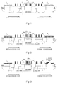
- FIG. 4 illustrates a first embodiment of the inventive method of transmitting client signals via a packet transport network with packet aggregation, e.g. a burst switched network.
- the method is implemented by means of an extension of the standard Generic Framing Procedure (GFP) as will be explained in the following.
- GFP Generic Framing Procedure
- Client packets 30a, 30b, 30c arrive at an ingress node of the network, e.g. at various times t 1 , t 2 and t 3 .
- the client packets 30a, 30b, 30c relate to different client signals.
- the client packets 30a, 30b, 30c may be, e.g. Ethernet frames and/or IP/PPP frames.
- the client packets 30a, 30b, 30c are encoded to a GFP encoded bit stream, i.e. the packets 30a, 30b, 30c are mapped to GFP client data frames 31a, 31b, 31c. Further, GFP idle frames 32 are placed between the GFP client data frames 31a, 31b, 31c to compensate for the gaps between the client packets 30a, 30b, 30c.
- GFP-F frame-mapped GFP
- GFP-T transparent-mapped GFP
- GFP-F the essentially entire client packet is mapped into a GFP client data frame, whereas in GFP-T multiple 8B/10B block coded client data streams are mapped to a GFP frame.
- GFP-F is typically used for Ethernet or IP/PPP client signals, whereas GFP-T is applied in case of Fiber Channel, ESCON (Enterprise Systems Connection) or FICON (Fiber Connectivity) client signals.
- Each GFP client data frame 31 a, 31b, 31c comprises a core header field (not shown), the core header field describing the GFP field, in particular the length of the payload. Further, each GFP client data frame 31 a, 31b, 31c comprises a payload area, with the payload area having a payload header 31.1a, 31.1b, 31.1c and a payload information field 31.2a, 31.2b, 31.2c. The client packets 30a, 30b, 30c are mapped to the payload information fields 31.2a, 31.2b, 31.2c.
- the GFP idle frames 32 (forming special GFP control frames) between the GFP client data frames 31 a, 31b, 31c comprise core header fields but no payload area and have a length of 4 bytes each.
- the GFP idle frames 32 between two subsequent GFP client data frames 31a, 31b, 31c are counted by a counter.
- the counter value is stored into a spare field of the GFP payload header of the GFP client data frame directly following the respective idle period being formed by the counted GFP idle frames 32.
- the counter value may be stored in a spare field of the extension header as part of the payload header.
- one may define a new extension header type since the extension header identifier (EXI) field allows further type definitions.
- the size of the extension header is not fixed but may vary between 0 and 58 bytes in dependency of the type.
- the counter value may be stored in the GFP core header or in an extended GFP core header.
- the GFP idle frames are removed from the bit stream. Both the step of counting left out idle frames and the step of removing the idle frames are not part of the conventional GFP as defined in the ITU-T G.7041 recommendation. Thus, in this embodiment a modified GFP is performed.
- the GFP client data frames 31a, 31b, 31c comprising the numbers of left out GFP idle frames in the payload header fields 31.1a, 31.1b, 31.1c (see "header*" comprising the number of left out idle frames, as illustrated in Fig. 4 ) are mapped directly one after another in a container 33, e.g. a burst container 33.
- the payload of the container 33 i.e. the packets 31a, 31b and 31c and its headers are not visible for the network nodes, thereby reducing the effort for header processing since only the header (not shown) of the container 33 and not the headers of the encapsulated packets needs to be processed.
- the process is reversed at the egress node, i.e. at the unloading stage the packet arrival process is mimicked by reestablishing the corrected departed distances as stored in the header fields 31.1a, 31.1b, 31.1c.
- the correct number of idle frames is reproduced based on the transmitted counter value of left out idle frames as stored in the payload header fields 31.1a, 31.1b, 31.1c and before the packet itself is released from the container for further transmission.
- the correct number of idle frames are inserted between the received GFP client data frames 31 a, 31b, 31 c, thereby reconstructing the timing at the ingress node.
- the client packets 30a, 30b, 30c are demapped from the GFP encoded bit steam with reconstructed timing.
- the departure timing of the client packets 30a, 30b, 30c for transmission via the access network essentially corresponds to the arrival timing of the client packets 30a, 30b, 30c at the ingress node.
- variable traffic load at the ingress node of such network further results in variable accumulation times for accumulating packets assigned to a container.
- This uncertainty in the accumulation time results in temporal variations of the delay between subsequent containers at the egress node and thus in jitter of packet arrival after de-aggregation.
- Such variation in the accumulation time due to traffic variations may be compensated as discussed below in a second embodiment of the inventive method. As a result not only the relative timing of packets in the same container but also the relative timing of packets in different containers is reconstructed at the egress node.
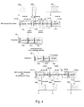
- the second embodiment of the inventive method as illustrated in Fig. 5 performs aggregation of client packets into containers and de-aggregation of client packets from a transmitted container by the following steps:
- the delivery is time-out controlled.
- the delivery is frame size controlled.
- each packet 40a-40e has to wait in the first 41 and second 43 FIFO buffers together for the constant time-out period To. This is explained below with reference to several examples.
- the relative distance for this first packet is set to the remainder of the time-out period To, i.e. to 0.
- Identical waiting times occur in case of a frame-size controlled scenario.
- a first packet arriving at time t 1 into an empty first FIFO buffer 41 which is subsequently completely filled before the time-out period lapses.
- the first FIFO buffer 41 is filled at a time t, with t ⁇ t 1 +T 0 .
- the relative distance for this first packet is set to the remainder of the time-out period To, i.e. to To - ⁇ t (1) .
- the total waiting time for all packets may be optionally increased by an additional constant delay.
- the first packet is not released immediately but after an additional constant time period.
- link capacity divided by jumbo frame size of 9.6 kbyte.
- time-out period T 0 1 ms
- time-out period is roughly equivalent to the delay of 200 km additional fiber distance (end-to-end, not between switching nodes of the network) or 1.25 Mbyte queue size in one of the intermediate switches.
- This traffic is less than 1/100 of the link capacity.
- the delivery is time-out controlled.
Landscapes
- Engineering & Computer Science (AREA)
- Computer Networks & Wireless Communication (AREA)
- Signal Processing (AREA)
- Data Exchanges In Wide-Area Networks (AREA)
- Communication Control (AREA)
- Packages (AREA)
Priority Applications (6)
| Application Number | Priority Date | Filing Date | Title |
|---|---|---|---|
| EP08155314A EP2079204B1 (fr) | 2007-12-17 | 2008-04-28 | Transport de paquets client agrégés |
| PCT/EP2008/067322 WO2009077419A1 (fr) | 2007-12-17 | 2008-12-11 | Transport de paquets clients agrégés |
| US12/316,285 US7876785B2 (en) | 2007-12-17 | 2008-12-11 | Transport of aggregated client packets |
| KR1020107013276A KR101130098B1 (ko) | 2007-12-17 | 2008-12-11 | 집합된 클라이언트 패킷들의 이송 |
| JP2010538597A JP5148716B2 (ja) | 2007-12-17 | 2008-12-11 | 集約されたクライアントパケットのトランスポート |
| CN2008101871485A CN101465805B (zh) | 2007-12-17 | 2008-12-17 | 集合的客户端分组的传输 |
Applications Claiming Priority (2)
| Application Number | Priority Date | Filing Date | Title |
|---|---|---|---|
| EP07291541A EP2073459A1 (fr) | 2007-12-17 | 2007-12-17 | Transmission via un réseau commuté en rafale ou en cadre avec préservation temporelle des paquets de clients transmis |
| EP08155314A EP2079204B1 (fr) | 2007-12-17 | 2008-04-28 | Transport de paquets client agrégés |
Publications (2)
| Publication Number | Publication Date |
|---|---|
| EP2079204A1 true EP2079204A1 (fr) | 2009-07-15 |
| EP2079204B1 EP2079204B1 (fr) | 2010-04-07 |
Family
ID=39358357
Family Applications (2)
| Application Number | Title | Priority Date | Filing Date |
|---|---|---|---|
| EP07291541A Withdrawn EP2073459A1 (fr) | 2007-12-17 | 2007-12-17 | Transmission via un réseau commuté en rafale ou en cadre avec préservation temporelle des paquets de clients transmis |
| EP08155314A Active EP2079204B1 (fr) | 2007-12-17 | 2008-04-28 | Transport de paquets client agrégés |
Family Applications Before (1)
| Application Number | Title | Priority Date | Filing Date |
|---|---|---|---|
| EP07291541A Withdrawn EP2073459A1 (fr) | 2007-12-17 | 2007-12-17 | Transmission via un réseau commuté en rafale ou en cadre avec préservation temporelle des paquets de clients transmis |
Country Status (8)
| Country | Link |
|---|---|
| US (1) | US7876785B2 (fr) |
| EP (2) | EP2073459A1 (fr) |
| JP (1) | JP5148716B2 (fr) |
| KR (1) | KR101130098B1 (fr) |
| CN (1) | CN101465805B (fr) |
| AT (1) | ATE463909T1 (fr) |
| DE (1) | DE602008000971D1 (fr) |
| WO (1) | WO2009077419A1 (fr) |
Families Citing this family (19)
| Publication number | Priority date | Publication date | Assignee | Title |
|---|---|---|---|---|
| EP2099191A1 (fr) * | 2008-03-03 | 2009-09-09 | Deutsche Thomson OHG | Conteneur de transport de données pour transférer des données dans un réseau de protocole Internet à grande vitesse |
| US8509193B2 (en) * | 2009-07-21 | 2013-08-13 | Microsoft Corporation | Packet aggregation |
| US8279891B2 (en) * | 2009-12-15 | 2012-10-02 | Cisco Technology, Inc. | Techniques for ethernet optical reach improvement |
| CN102870390A (zh) * | 2010-04-30 | 2013-01-09 | 诺基亚西门子通信公司 | 减小语音业务上的开销 |
| JP5978792B2 (ja) * | 2012-06-12 | 2016-08-24 | 富士通株式会社 | 伝送装置及び伝送方法 |
| WO2014015918A1 (fr) * | 2012-07-26 | 2014-01-30 | Telefonaktiebolaget L M Ericsson (Publ) | Procédé et appareil pour transporter un signal de client sur un réseau optique |
| US9577955B2 (en) * | 2013-03-12 | 2017-02-21 | Forrest Lawrence Pierson | Indefinitely expandable high-capacity data switch |
| CN106164344B (zh) | 2014-02-07 | 2018-12-18 | 韩国生命工学研究院 | 使用流式细胞仪测定蛋白纳米颗粒分子间相互作用的方法 |
| EP2911325B1 (fr) * | 2014-02-25 | 2016-09-14 | Alcatel Lucent | Détection de défaillance de gcc rapide |
| US10171430B2 (en) | 2015-07-27 | 2019-01-01 | Forrest L. Pierson | Making a secure connection over insecure lines more secure |
| US11675587B2 (en) | 2015-12-03 | 2023-06-13 | Forrest L. Pierson | Enhanced protection of processors from a buffer overflow attack |
| US10564969B2 (en) | 2015-12-03 | 2020-02-18 | Forrest L. Pierson | Enhanced protection of processors from a buffer overflow attack |
| US20170171085A1 (en) * | 2015-12-15 | 2017-06-15 | Huawei Technologies Co., Ltd. | Traffic Engineering System and Method for a Communications Network |
| CN105827353B (zh) * | 2016-03-11 | 2018-02-16 | 烽火通信科技股份有限公司 | 一种基于wrr的otn串行化均衡调度实现方法及系统 |
| CN107786320B (zh) | 2016-08-25 | 2021-06-22 | 华为技术有限公司 | 一种发送和接收业务的方法、装置和网络系统 |
| CN107786299B (zh) | 2016-08-25 | 2021-06-08 | 华为技术有限公司 | 一种发送和接收业务的方法、装置和网络系统 |
| GB201804479D0 (en) * | 2018-03-21 | 2018-05-02 | Nchain Holdings Ltd | Computer-implemented system and method |
| US11295334B2 (en) * | 2019-04-30 | 2022-04-05 | Bank Of America Corporation | Batch transaction multiplexing engine |
| CN112751645A (zh) * | 2019-10-29 | 2021-05-04 | 华为技术有限公司 | 一种通信方法、设备及存储介质 |
Citations (6)
| Publication number | Priority date | Publication date | Assignee | Title |
|---|---|---|---|---|
| EP1089498A2 (fr) * | 1999-09-30 | 2001-04-04 | Alcatel | Architecture de contrôle dans des réseaux optiques avec commutation en rafale |
| US20030126294A1 (en) | 2001-11-19 | 2003-07-03 | Thorsteinson Thomas M. | Transmitting digital video signals over an IP network |
| US20040156390A1 (en) * | 2003-02-12 | 2004-08-12 | Cisco Technology, Inc. | Efficient framing procedure for variable length packets |
| EP1455494A2 (fr) | 2003-03-05 | 2004-09-08 | Akara Corporation | Procédé et dispositif pour préserver des informations de régulation à travers un media de transport |
| US6813259B1 (en) * | 1997-07-15 | 2004-11-02 | Viasat, Inc. | Method and apparatus for minimizing delay variance via time divided transmissions |
| US20040252720A1 (en) | 2003-06-10 | 2004-12-16 | Cisco Technology, Inc. | Fibre channel frame-mode GFP with distributed delimiter |
Family Cites Families (13)
| Publication number | Priority date | Publication date | Assignee | Title |
|---|---|---|---|---|
| DE3241525A1 (de) * | 1982-11-10 | 1984-05-10 | Wabco Westinghouse Steuerungstechnik GmbH & Co, 3000 Hannover | Einrichtung zum erfassen der position oder/und der geschwindigkeit des kolbens eines arbeitszylinders |
| JP2000332817A (ja) * | 1999-05-18 | 2000-11-30 | Fujitsu Ltd | パケット処理装置 |
| EP1069736B1 (fr) * | 1999-07-15 | 2012-09-05 | TELEFONAKTIEBOLAGET LM ERICSSON (publ) | Ordonnancement et contrôle d'admission du trafic de paquets de données |
| US7391760B1 (en) * | 2000-08-21 | 2008-06-24 | Nortel Networks Limited | Method and apparatus for efficient protocol-independent trunking of data signals |
| US7301948B2 (en) * | 2001-06-28 | 2007-11-27 | Ntt Docomo, Inc. | Routing method, node, packet communication system, program, and recording medium |
| US7120168B2 (en) * | 2001-11-20 | 2006-10-10 | Sony Corporation | System and method for effectively performing an audio/video synchronization procedure |
| US6801545B2 (en) * | 2002-02-04 | 2004-10-05 | Fujitsu Network Communications, Inc. | Container transport for packets in connection oriented protocols |
| US6934776B2 (en) * | 2002-07-16 | 2005-08-23 | Intel Corporation | Methods and apparatus for determination of packet sizes when transferring packets via a network |
| US7376141B2 (en) * | 2002-12-17 | 2008-05-20 | Raytheon Company | Method and system for encapsulating variable-size packets |
| US7391769B2 (en) * | 2003-06-27 | 2008-06-24 | Lucent Technologies Inc. | Packet aggregation for real time services on packet data networks |
| JP4059857B2 (ja) * | 2004-03-02 | 2008-03-12 | 富士通株式会社 | 伝送装置及び伝送方法 |
| US7463642B2 (en) * | 2004-04-07 | 2008-12-09 | Cisco Technology, Inc. | Multiple receiver aggregation |
| US7822075B2 (en) * | 2004-04-09 | 2010-10-26 | Utstarcom Telecom Co., Ltd. | Method and system of signal transmission in base transceiver station based on remote radio head |
-
2007
- 2007-12-17 EP EP07291541A patent/EP2073459A1/fr not_active Withdrawn
-
2008
- 2008-04-28 AT AT08155314T patent/ATE463909T1/de not_active IP Right Cessation
- 2008-04-28 EP EP08155314A patent/EP2079204B1/fr active Active
- 2008-04-28 DE DE602008000971T patent/DE602008000971D1/de active Active
- 2008-12-11 JP JP2010538597A patent/JP5148716B2/ja active Active
- 2008-12-11 US US12/316,285 patent/US7876785B2/en active Active
- 2008-12-11 WO PCT/EP2008/067322 patent/WO2009077419A1/fr active Application Filing
- 2008-12-11 KR KR1020107013276A patent/KR101130098B1/ko active IP Right Grant
- 2008-12-17 CN CN2008101871485A patent/CN101465805B/zh active Active
Patent Citations (6)
| Publication number | Priority date | Publication date | Assignee | Title |
|---|---|---|---|---|
| US6813259B1 (en) * | 1997-07-15 | 2004-11-02 | Viasat, Inc. | Method and apparatus for minimizing delay variance via time divided transmissions |
| EP1089498A2 (fr) * | 1999-09-30 | 2001-04-04 | Alcatel | Architecture de contrôle dans des réseaux optiques avec commutation en rafale |
| US20030126294A1 (en) | 2001-11-19 | 2003-07-03 | Thorsteinson Thomas M. | Transmitting digital video signals over an IP network |
| US20040156390A1 (en) * | 2003-02-12 | 2004-08-12 | Cisco Technology, Inc. | Efficient framing procedure for variable length packets |
| EP1455494A2 (fr) | 2003-03-05 | 2004-09-08 | Akara Corporation | Procédé et dispositif pour préserver des informations de régulation à travers un media de transport |
| US20040252720A1 (en) | 2003-06-10 | 2004-12-16 | Cisco Technology, Inc. | Fibre channel frame-mode GFP with distributed delimiter |
Also Published As
| Publication number | Publication date |
|---|---|
| KR20100086055A (ko) | 2010-07-29 |
| KR101130098B1 (ko) | 2012-03-28 |
| CN101465805A (zh) | 2009-06-24 |
| JP2011507430A (ja) | 2011-03-03 |
| WO2009077419A8 (fr) | 2009-08-06 |
| US7876785B2 (en) | 2011-01-25 |
| CN101465805B (zh) | 2011-12-28 |
| EP2073459A1 (fr) | 2009-06-24 |
| WO2009077419A1 (fr) | 2009-06-25 |
| US20090154475A1 (en) | 2009-06-18 |
| EP2079204B1 (fr) | 2010-04-07 |
| JP5148716B2 (ja) | 2013-02-20 |
| ATE463909T1 (de) | 2010-04-15 |
| DE602008000971D1 (de) | 2010-05-20 |
Similar Documents
| Publication | Publication Date | Title |
|---|---|---|
| US7876785B2 (en) | Transport of aggregated client packets | |
| US20090180478A1 (en) | Ethernet switching method and ethernet switch | |
| US7583664B2 (en) | Techniques for transmitting and receiving traffic over advanced switching compatible switch fabrics | |
| US8289962B2 (en) | Multi-component compatible data architecture | |
| US8532094B2 (en) | Multi-network compatible data architecture | |
| ES2336730T3 (es) | Sistema de comunicacion. | |
| US20080240169A1 (en) | Method, system and device for clock transmission between sender and receiver | |
| US6999479B1 (en) | Hybrid data transport scheme over optical networks | |
| EP1509007A1 (fr) | Procédé et système pour la compensation du décalage en fréquence dans le transport de trames Ethernet sur un réseau du transport | |
| US20060140226A1 (en) | Techniques for processing traffic transmitted over advanced switching compatible switch fabrics | |
| US6510166B2 (en) | Stuffing filter mechanism for data transmission signals | |
| EP1339198B1 (fr) | Transport renforcée du trafic Ethernet par un réseau du transport SDH/sonet (HNS) | |
| CN108737911B (zh) | 基于广义光突发交换的potn业务承载方法及系统 | |
| CN113508543B (zh) | 用于将恒定比特率客户端信号适配到电信信号的路径层中的方法 | |
| US11838111B2 (en) | System and method for performing rate adaptation of constant bit rate (CBR) client data with a variable number of idle blocks for transmission over a metro transport network (MTN) | |
| US20230006938A1 (en) | System and method for performing rate adaptation and multiplexing of constant bit rate (cbr) client data for transmission over a metro transport network (mtn) | |
| Nguyên | TELECOM & Management SudParis, 9 Rue Charles Fourier, 91011 Evry, France; e-mail:{viet_hung. nguyen, tulin. atmaca}@ it-sudparis. eu | |
| CN118055076A (zh) | 一种报文处理方法、信息处理方法及装置 | |
| CN113949743A (zh) | Odu净荷承载方法及系统 | |
| JP2013123111A (ja) | パケット多重伝送装置及び方法 | |
| EP1052807A1 (fr) | Réseau de communications utilisant classes de priorité | |
| Liu et al. | A single chip solution of dual-gigabit Ethernet over 2.5 G SDH/SONET | |
| Klymash et al. | Calculation efficiency to use capacity channel for different kinds of traffic and network technologies | |
| JP2015207839A (ja) | 通信システムおよび通信装置 |
Legal Events
| Date | Code | Title | Description |
|---|---|---|---|
| PUAI | Public reference made under article 153(3) epc to a published international application that has entered the european phase |
Free format text: ORIGINAL CODE: 0009012 |
|
| 17P | Request for examination filed |
Effective date: 20090127 |
|
| AK | Designated contracting states |
Kind code of ref document: A1 Designated state(s): AT BE BG CH CY CZ DE DK EE ES FI FR GB GR HR HU IE IS IT LI LT LU LV MC MT NL NO PL PT RO SE SI SK TR |
|
| AX | Request for extension of the european patent |
Extension state: AL BA MK RS |
|
| 17Q | First examination report despatched |
Effective date: 20090701 |
|
| GRAP | Despatch of communication of intention to grant a patent |
Free format text: ORIGINAL CODE: EPIDOSNIGR1 |
|
| GRAS | Grant fee paid |
Free format text: ORIGINAL CODE: EPIDOSNIGR3 |
|
| GRAA | (expected) grant |
Free format text: ORIGINAL CODE: 0009210 |
|
| AKX | Designation fees paid |
Designated state(s): AT BE BG CH CY CZ DE DK EE ES FI FR GB GR HR HU IE IS IT LI LT LU LV MC MT NL NO PL PT RO SE SI SK TR |
|
| AK | Designated contracting states |
Kind code of ref document: B1 Designated state(s): AT BE BG CH CY CZ DE DK EE ES FI FR GB GR HR HU IE IS IT LI LT LU LV MC MT NL NO PL PT RO SE SI SK TR |
|
| REG | Reference to a national code |
Ref country code: GB Ref legal event code: FG4D |
|
| REG | Reference to a national code |
Ref country code: CH Ref legal event code: EP |
|
| REG | Reference to a national code |
Ref country code: IE Ref legal event code: FG4D |
|
| REF | Corresponds to: |
Ref document number: 602008000971 Country of ref document: DE Date of ref document: 20100520 Kind code of ref document: P |
|
| REG | Reference to a national code |
Ref country code: NL Ref legal event code: VDEP Effective date: 20100407 |
|
| PG25 | Lapsed in a contracting state [announced via postgrant information from national office to epo] |
Ref country code: SI Free format text: LAPSE BECAUSE OF FAILURE TO SUBMIT A TRANSLATION OF THE DESCRIPTION OR TO PAY THE FEE WITHIN THE PRESCRIBED TIME-LIMIT Effective date: 20100407 |
|
| LTIE | Lt: invalidation of european patent or patent extension |
Effective date: 20100407 |
|
| PG25 | Lapsed in a contracting state [announced via postgrant information from national office to epo] |
Ref country code: SE Free format text: LAPSE BECAUSE OF FAILURE TO SUBMIT A TRANSLATION OF THE DESCRIPTION OR TO PAY THE FEE WITHIN THE PRESCRIBED TIME-LIMIT Effective date: 20100407 Ref country code: NO Free format text: LAPSE BECAUSE OF FAILURE TO SUBMIT A TRANSLATION OF THE DESCRIPTION OR TO PAY THE FEE WITHIN THE PRESCRIBED TIME-LIMIT Effective date: 20100707 Ref country code: NL Free format text: LAPSE BECAUSE OF FAILURE TO SUBMIT A TRANSLATION OF THE DESCRIPTION OR TO PAY THE FEE WITHIN THE PRESCRIBED TIME-LIMIT Effective date: 20100407 Ref country code: LT Free format text: LAPSE BECAUSE OF FAILURE TO SUBMIT A TRANSLATION OF THE DESCRIPTION OR TO PAY THE FEE WITHIN THE PRESCRIBED TIME-LIMIT Effective date: 20100407 Ref country code: ES Free format text: LAPSE BECAUSE OF FAILURE TO SUBMIT A TRANSLATION OF THE DESCRIPTION OR TO PAY THE FEE WITHIN THE PRESCRIBED TIME-LIMIT Effective date: 20100718 |
|
| PG25 | Lapsed in a contracting state [announced via postgrant information from national office to epo] |
Ref country code: MC Free format text: LAPSE BECAUSE OF NON-PAYMENT OF DUE FEES Effective date: 20100430 Ref country code: AT Free format text: LAPSE BECAUSE OF FAILURE TO SUBMIT A TRANSLATION OF THE DESCRIPTION OR TO PAY THE FEE WITHIN THE PRESCRIBED TIME-LIMIT Effective date: 20100407 Ref country code: FI Free format text: LAPSE BECAUSE OF FAILURE TO SUBMIT A TRANSLATION OF THE DESCRIPTION OR TO PAY THE FEE WITHIN THE PRESCRIBED TIME-LIMIT Effective date: 20100407 Ref country code: HR Free format text: LAPSE BECAUSE OF FAILURE TO SUBMIT A TRANSLATION OF THE DESCRIPTION OR TO PAY THE FEE WITHIN THE PRESCRIBED TIME-LIMIT Effective date: 20100407 Ref country code: IS Free format text: LAPSE BECAUSE OF FAILURE TO SUBMIT A TRANSLATION OF THE DESCRIPTION OR TO PAY THE FEE WITHIN THE PRESCRIBED TIME-LIMIT Effective date: 20100807 Ref country code: LV Free format text: LAPSE BECAUSE OF FAILURE TO SUBMIT A TRANSLATION OF THE DESCRIPTION OR TO PAY THE FEE WITHIN THE PRESCRIBED TIME-LIMIT Effective date: 20100407 |
|
| PG25 | Lapsed in a contracting state [announced via postgrant information from national office to epo] |
Ref country code: CY Free format text: LAPSE BECAUSE OF FAILURE TO SUBMIT A TRANSLATION OF THE DESCRIPTION OR TO PAY THE FEE WITHIN THE PRESCRIBED TIME-LIMIT Effective date: 20100616 Ref country code: PL Free format text: LAPSE BECAUSE OF FAILURE TO SUBMIT A TRANSLATION OF THE DESCRIPTION OR TO PAY THE FEE WITHIN THE PRESCRIBED TIME-LIMIT Effective date: 20100407 |
|
| PG25 | Lapsed in a contracting state [announced via postgrant information from national office to epo] |
Ref country code: DK Free format text: LAPSE BECAUSE OF FAILURE TO SUBMIT A TRANSLATION OF THE DESCRIPTION OR TO PAY THE FEE WITHIN THE PRESCRIBED TIME-LIMIT Effective date: 20100407 Ref country code: EE Free format text: LAPSE BECAUSE OF FAILURE TO SUBMIT A TRANSLATION OF THE DESCRIPTION OR TO PAY THE FEE WITHIN THE PRESCRIBED TIME-LIMIT Effective date: 20100407 Ref country code: IE Free format text: LAPSE BECAUSE OF NON-PAYMENT OF DUE FEES Effective date: 20100428 |
|
| PLBE | No opposition filed within time limit |
Free format text: ORIGINAL CODE: 0009261 |
|
| STAA | Information on the status of an ep patent application or granted ep patent |
Free format text: STATUS: NO OPPOSITION FILED WITHIN TIME LIMIT |
|
| PG25 | Lapsed in a contracting state [announced via postgrant information from national office to epo] |
Ref country code: RO Free format text: LAPSE BECAUSE OF FAILURE TO SUBMIT A TRANSLATION OF THE DESCRIPTION OR TO PAY THE FEE WITHIN THE PRESCRIBED TIME-LIMIT Effective date: 20100407 Ref country code: SK Free format text: LAPSE BECAUSE OF FAILURE TO SUBMIT A TRANSLATION OF THE DESCRIPTION OR TO PAY THE FEE WITHIN THE PRESCRIBED TIME-LIMIT Effective date: 20100407 Ref country code: BE Free format text: LAPSE BECAUSE OF FAILURE TO SUBMIT A TRANSLATION OF THE DESCRIPTION OR TO PAY THE FEE WITHIN THE PRESCRIBED TIME-LIMIT Effective date: 20100407 Ref country code: CZ Free format text: LAPSE BECAUSE OF FAILURE TO SUBMIT A TRANSLATION OF THE DESCRIPTION OR TO PAY THE FEE WITHIN THE PRESCRIBED TIME-LIMIT Effective date: 20100407 |
|
| 26N | No opposition filed |
Effective date: 20110110 |
|
| PG25 | Lapsed in a contracting state [announced via postgrant information from national office to epo] |
Ref country code: IT Free format text: LAPSE BECAUSE OF FAILURE TO SUBMIT A TRANSLATION OF THE DESCRIPTION OR TO PAY THE FEE WITHIN THE PRESCRIBED TIME-LIMIT Effective date: 20100407 |
|
| PG25 | Lapsed in a contracting state [announced via postgrant information from national office to epo] |
Ref country code: MT Free format text: LAPSE BECAUSE OF FAILURE TO SUBMIT A TRANSLATION OF THE DESCRIPTION OR TO PAY THE FEE WITHIN THE PRESCRIBED TIME-LIMIT Effective date: 20100407 |
|
| PG25 | Lapsed in a contracting state [announced via postgrant information from national office to epo] |
Ref country code: GR Free format text: LAPSE BECAUSE OF FAILURE TO SUBMIT A TRANSLATION OF THE DESCRIPTION OR TO PAY THE FEE WITHIN THE PRESCRIBED TIME-LIMIT Effective date: 20100708 |
|
| PG25 | Lapsed in a contracting state [announced via postgrant information from national office to epo] |
Ref country code: BG Free format text: LAPSE BECAUSE OF FAILURE TO SUBMIT A TRANSLATION OF THE DESCRIPTION OR TO PAY THE FEE WITHIN THE PRESCRIBED TIME-LIMIT Effective date: 20100407 Ref country code: LU Free format text: LAPSE BECAUSE OF NON-PAYMENT OF DUE FEES Effective date: 20100428 Ref country code: PT Free format text: LAPSE BECAUSE OF FAILURE TO SUBMIT A TRANSLATION OF THE DESCRIPTION OR TO PAY THE FEE WITHIN THE PRESCRIBED TIME-LIMIT Effective date: 20100907 Ref country code: HU Free format text: LAPSE BECAUSE OF FAILURE TO SUBMIT A TRANSLATION OF THE DESCRIPTION OR TO PAY THE FEE WITHIN THE PRESCRIBED TIME-LIMIT Effective date: 20101008 |
|
| PG25 | Lapsed in a contracting state [announced via postgrant information from national office to epo] |
Ref country code: TR Free format text: LAPSE BECAUSE OF FAILURE TO SUBMIT A TRANSLATION OF THE DESCRIPTION OR TO PAY THE FEE WITHIN THE PRESCRIBED TIME-LIMIT Effective date: 20100407 |
|
| REG | Reference to a national code |
Ref country code: CH Ref legal event code: PL |
|
| PG25 | Lapsed in a contracting state [announced via postgrant information from national office to epo] |
Ref country code: LI Free format text: LAPSE BECAUSE OF NON-PAYMENT OF DUE FEES Effective date: 20120430 Ref country code: CH Free format text: LAPSE BECAUSE OF NON-PAYMENT OF DUE FEES Effective date: 20120430 |
|
| PG25 | Lapsed in a contracting state [announced via postgrant information from national office to epo] |
Ref country code: BG Free format text: LAPSE BECAUSE OF FAILURE TO SUBMIT A TRANSLATION OF THE DESCRIPTION OR TO PAY THE FEE WITHIN THE PRESCRIBED TIME-LIMIT Effective date: 20100707 |
|
| REG | Reference to a national code |
Ref country code: GB Ref legal event code: 732E Free format text: REGISTERED BETWEEN 20130919 AND 20130925 |
|
| REG | Reference to a national code |
Ref country code: FR Ref legal event code: PLFP Year of fee payment: 8 |
|
| REG | Reference to a national code |
Ref country code: FR Ref legal event code: PLFP Year of fee payment: 9 |
|
| REG | Reference to a national code |
Ref country code: FR Ref legal event code: PLFP Year of fee payment: 10 |
|
| REG | Reference to a national code |
Ref country code: FR Ref legal event code: PLFP Year of fee payment: 11 |
|
| REG | Reference to a national code |
Ref country code: DE Ref legal event code: R081 Ref document number: 602008000971 Country of ref document: DE Owner name: META PLATFORMS, INC., MENLO PARK, US Free format text: FORMER OWNER: ALCATEL-LUCENT DEUTSCHLAND AG, 70435 STUTTGART, DE Ref country code: DE Ref legal event code: R081 Ref document number: 602008000971 Country of ref document: DE Owner name: PROVENANCE ASSET GROUP LLC, PITTSFORD, US Free format text: FORMER OWNER: ALCATEL-LUCENT DEUTSCHLAND AG, 70435 STUTTGART, DE |
|
| REG | Reference to a national code |
Ref country code: FR Ref legal event code: PLFP Year of fee payment: 15 |
|
| P01 | Opt-out of the competence of the unified patent court (upc) registered |
Effective date: 20230524 |
|
| PGFP | Annual fee paid to national office [announced via postgrant information from national office to epo] |
Ref country code: FR Payment date: 20230421 Year of fee payment: 16 Ref country code: DE Payment date: 20230428 Year of fee payment: 16 |
|
| PGFP | Annual fee paid to national office [announced via postgrant information from national office to epo] |
Ref country code: GB Payment date: 20230427 Year of fee payment: 16 |
|
| REG | Reference to a national code |
Ref country code: DE Ref legal event code: R081 Ref document number: 602008000971 Country of ref document: DE Owner name: META PLATFORMS, INC., MENLO PARK, US Free format text: FORMER OWNER: PROVENANCE ASSET GROUP LLC, PITTSFORD, NY, US |