EP2079190A1 - Fault location device, communication device, and fault location method - Google Patents
Fault location device, communication device, and fault location method Download PDFInfo
- Publication number
- EP2079190A1 EP2079190A1 EP09150204A EP09150204A EP2079190A1 EP 2079190 A1 EP2079190 A1 EP 2079190A1 EP 09150204 A EP09150204 A EP 09150204A EP 09150204 A EP09150204 A EP 09150204A EP 2079190 A1 EP2079190 A1 EP 2079190A1
- Authority
- EP
- European Patent Office
- Prior art keywords
- communication
- error
- error counter
- accumulated value
- communication device
- Prior art date
- Legal status (The legal status is an assumption and is not a legal conclusion. Google has not performed a legal analysis and makes no representation as to the accuracy of the status listed.)
- Granted
Links
Images


Classifications
-
- H—ELECTRICITY
- H04—ELECTRIC COMMUNICATION TECHNIQUE
- H04L—TRANSMISSION OF DIGITAL INFORMATION, e.g. TELEGRAPHIC COMMUNICATION
- H04L43/00—Arrangements for monitoring or testing data switching networks
- H04L43/08—Monitoring or testing based on specific metrics, e.g. QoS, energy consumption or environmental parameters
- H04L43/0823—Errors, e.g. transmission errors
-
- H—ELECTRICITY
- H04—ELECTRIC COMMUNICATION TECHNIQUE
- H04L—TRANSMISSION OF DIGITAL INFORMATION, e.g. TELEGRAPHIC COMMUNICATION
- H04L12/00—Data switching networks
- H04L12/28—Data switching networks characterised by path configuration, e.g. LAN [Local Area Networks] or WAN [Wide Area Networks]
- H04L12/40—Bus networks
- H04L2012/40208—Bus networks characterized by the use of a particular bus standard
- H04L2012/40215—Controller Area Network CAN
-
- H—ELECTRICITY
- H04—ELECTRIC COMMUNICATION TECHNIQUE
- H04L—TRANSMISSION OF DIGITAL INFORMATION, e.g. TELEGRAPHIC COMMUNICATION
- H04L12/00—Data switching networks
- H04L12/28—Data switching networks characterised by path configuration, e.g. LAN [Local Area Networks] or WAN [Wide Area Networks]
- H04L12/40—Bus networks
- H04L2012/40267—Bus for use in transportation systems
- H04L2012/40273—Bus for use in transportation systems the transportation system being a vehicle
Definitions
- the invention relates to a controller area network (CAN) communication system and method by which communications are carried out among a plurality of communication devices connected through a CAN bus and, more particularly, to a fault location device, communication device, and fault location method that are able to identify a fault point due to a one-wire break.
- CAN controller area network
- a known CAN communication system carries out data communications among a plurality of communication devices.
- the plurality of communication devices are connected with one another through a CAN bus, and each have a CAN controller unit.
- the CAN communication protocol allows bidirectional serial communication through a differential serial bus.
- each communication device transmits data with its own identification (ID) code to the CAN bus.
- ID identification
- the communication device transmits the data when the CAN bus is not occupied by data transmitted from another communication device, the data transmitted from the communication device flows through the CAN bus and reaches an intended communication device.
- the data which will be transmitted from the communication device, is queued in the CAN controller unit. Then, when there is only one communication device in which the data are queued, the queued data flow through the CAN bus when the CAN bus is unoccupied.
- the data of the highest-priority communication device on the basis of the ID code from among those communication devices flow through the CAN bus prior to the other queued data.
- the CAN communication system includes the plurality of communication devices (nodes). These plurality of communication devices are connected with one another through the CAN bus which is formed of twisted pair wires. The communication devices transmit and receive data to and from one another.
- the twisted pair wires of the CAN bus are bus wires, one of which is called CAN High (CANH) and the other one of which is called CAN Low (CANL).
- the communication devices may be, for example, formed of a plurality of electronic control units (ECUs) that control various portions of a vehicle.
- JP-A-2003-143164 describes a controller that is able to identify another faulty controller (ECU) at the time of intercommunication control.
- This controller observes a device that transmits and receives data to and from a communication line.
- the device includes a measurement unit that measures a period of time from the time when the preceding communication data are acquired to the time when the subsequent communication data are acquired, and a determination unit that determines a breakdown of communications when the measured time exceeds a predetermined determination time.
- the one-wire break includes a break that occurs in one of communication lines connected to a communication device and a contact failure that occurs in one of the communication lines connected to a communication device.
- the one-wire break occurs, it is no problem when the one-wire break continues and then can be repaired; however, there is a possibility that, for example, in the case of a contact failure, the communication line may be apparently connected before the one-wire break is repaired. In this case, the communication line is just apparently connected, so a contact failure occurs again when the communication line is pulled. Thus, a fault point may be identified by pulling the communication line.
- a vehicle is equipped with several hundreds of communication lines, it is practically impossible to identify the communication device, in which the contact failure is occurring, by pulling the communication lines.
- a communication device connected to the broken communication line when a one-side communication line is broken, a communication device connected to the broken communication line generates an abnormal voltage. This corrupts data transmitted from another communication device. As a result, data (message) from a normal communication device are also corrupted. As a consequence of corruption of the message transmitted from the normal communication device, the normal communicable communication device is also determined to be in a breakdown of communications. Thus, the normal communicable communication device is erroneously determined to be faulty.
- the invention provides a fault location device, communication device, and fault location method that are able to detect a communication device in which one of two wires connected to the communication device is broken.
- a first aspect of the invention provides a fault location device.
- the fault location device detects a communication device connected to a broken communication line from among first and second communication devices that carry out communications between each other through a two-wire communication line.
- each of the communication devices stores time of the communication error and a communication error counter accumulated value that indicates accumulated counts corresponding to the communication error, changes into a bus off state on the basis of the communication error counter accumulated value and then, after a predetermined period of time has elapsed, returns from the bus off state.
- the fault location device includes: an acquisition unit that acquires the time of the communication error and the communication error counter accumulated value, which are stored in each of the communication devices; and a detection unit that detects a communication device connected to a broken communication line on the basis of variations in the communication error counter accumulated values while any one of the communication devices is in a bus off state.
- the fault location device may be, for example, formed of a service tool.
- the communication error may include a transmission error and a reception error.
- Each of the communication devices may store a transmission error counter accumulated value that indicates accumulated counts corresponding to the transmission error and a reception error counter accumulated value that indicates accumulated counts corresponding to the reception error.
- the detection unit may determine that a communication line connected to that communication device is broken.
- the communication error may include a transmission error and a reception error.
- Each of the communication devices may store a transmission error counter accumulated value that indicates accumulated counts corresponding to the transmission error and a reception error counter accumulated value that indicates accumulated counts corresponding to the reception error.
- the detection unit may determine that a communication line connected to the communication device which is in the bus off state is broken.
- a second aspect of the invention provides a first communication device in a communication system formed of the first communication device and a second communication device.
- the first communication device and the second communication device carry out communications between each other through a two-wire communication line.
- the first communication device includes: a storage unit that stores time of a communication error and a communication error counter accumulated value that indicates accumulated counts corresponding to the communication error; a control unit that changes the first communication device into a bus off state on the basis of the communication error counter accumulated value and then, after a predetermined period of time has elapsed, returns the first communication device from the bus off state; an acquisition unit that acquires the time of the communication error and the communication error counter accumulated value, which are stored in each of the communication devices; and a detection unit that detects a communication device connected to a broken communication line on the basis of variations in the communication error counter accumulated values while one of the first and second communication devices is in a bus off state.
- the first communication device may be formed of a communication device that has, for example, a master function.
- the communication error may include a transmission error and a reception error.
- the storage unit may store a transmission error counter accumulated value that indicates accumulated counts corresponding to the transmission error and a reception error counter accumulated value that indicates accumulated counts corresponding to the reception error.
- the detection unit may determine that a communication line connected to that communication device is broken.
- the communication error may include a transmission error and a reception error.
- the storage unit may store a transmission error counter accumulated value that indicates accumulated counts corresponding to the transmission error and a reception error counter accumulated value that indicates accumulated counts corresponding to the reception error.
- the detection unit may determine that a communication line connected to the communication device which has been in the bus off state is broken.
- a third aspect of the invention provides a fault location method for detecting a communication device connected to a broken communication line from among first and second communication devices that carry out communications between each other through a two-wire communication line.
- the fault location method includes: when a communication error has been detected by the first communication device, storing time of the communication error and a communication error counter accumulated value that indicates accumulated counts corresponding to the communication error; changing the first communication device into a bus off state on the basis of the communication error counter accumulated value and then, after a predetermined period of time has elapsed, returning the first communication device from the bus off state; acquiring the time of the communication error and the communication error counter accumulated value, which are stored in each of the first and second communication devices; and detecting a communication device connected to a broken communication line on the basis of variations in the communication error counter accumulated values of each of the communication devices while one of the first and second communication devices is in a bus off state.
- the fault location method may be, for example, executed by a service tool.
- the communication error may include a transmission error and a reception error.
- a transmission error counter accumulated value that indicates accumulated counts corresponding to the transmission error and a reception error counter accumulated value that indicates accumulated counts corresponding to the reception error may be stored.
- fault location device communication device and fault location method, it is possible to detect a communication device in which one of two wires connected to the communication device is broken.
- FIG. 1 also shows a DLC 450 and a fault location device 500.
- the DLC 450 and the fault location device 500 are connected to the CAN communication system when a fault point is detected.
- the CAN communication system 1000 includes a plurality of communication devices that carry out communications in accordance with the communication protocol of an in-vehicle LAN.
- the communication protocol of the in-vehicle LAN may employ a controller area network (CAN).
- the communication devices are respectively formed of a plurality of electronic control units (ECUs) that control various portions of a vehicle.
- a communication line uses a two-wire CAN communication line 400 formed of a CANH 200 and a CANL 300, and a terminator is connected at each end of the two-wire CAN communication line 400. Then, in the CAN, a transmitting communication device transmits inverted signals to the CANH 200 and the CANL 300, and a receiving communication device determines, on the basis of a voltage difference between the CANH 200 and the CANL 300, whether a piece of data on the CAN communication line 400 is "1" or "0".
- Each of the ECUs 100 1 to 100 3 includes a CPU 102 (102 1 , 102 2 , and 102 3 ), a communication driver 104 (104 1 , 104 2 , and 104 3 ), and a storage unit 106 (106 1 , 106 2 , and 106 3 ).
- Each CPU 102 executes a control process for controlling various portions of the vehicle and a process for carrying out communications with another ECU.
- Each communication driver 104 is connected to the above described two-wire CAN communication line 400.
- Each communication driver 104 outputs transmission data, transferred from the CPU 102, to the two-wire CAN communication line 400, and inputs data on the two-wire CAN communication line 400 into the CPU 102.
- Each storage unit 106 stores a communication error detected by the CPU 102.
- the communication error includes a transmission error and a reception error.
- Each communication driver 104 includes first and second output buffers (two output buffers) and a binarization circuit.
- the first output buffer sets the voltage of the CANH 200 to a high level (for example, 3.5 V) when the transmission data is "0", or sets the voltage of the CANH 200 to a low level (for example, 2.5 V) when the transmission data is "1".
- the second output buffer sets the voltage of the CANL 300 to a low level (for example, 1.5 V) when the transmission data is "0", or sets the voltage of the CANL 300 to a high level (for example, 2.5 V) when the transmission data is "1".
- the binarization circuit generates a binary signal "1" or "0” that indicates the data on the CAN communication line 400 on the basis of a difference between a voltage input to the CANH 200 and a voltage input to the CANL 300.
- the CPU 102 monitors the condition of CAN communication and detects a communication error.
- the CPU 102 monitors the condition of CAN communication and detects a reception error and/or a transmission error as the communication error.
- the communication error includes any one of a bit error, a stuff error, a cyclic redundancy check (CRC) error, a form error, and an authentication error.
- the communication device which transmits data, monitors the bus at the same time.
- the bit error is detected when a monitoring bit is different from a transmitted bit.
- the stuff error is detected when successive six bits have the same bit level against a bit-stuffing rule.
- a CRC sequence contains a CRC calculation result calculated in a transmitter.
- the CRC error is detected when a receiver calculates a CRC and the calculated CRC is different from the above CRC calculation result.
- the form error is detected when a field whose number of bits is fixed contains an invalid bit.
- the authentication error is detected by the transmitter when an ACK slot from a receiver does not return a dominant bit.
- the CPU 102 updates an error counter value, which is determined beforehand in correspondence with a communication error, in accordance with the detected communication error. For example, the CPU 102 detects a transmission error and/or a reception error, increases a transmission error counter value (TEC), corresponding to the transmission error, and/or a reception error counter value (REC), corresponding to the reception error, and then obtains a transmission error counter accumulated value and/or a reception error counter accumulated value.
- the transmission error counter accumulated value represents accumulated counts corresponding to the transmission error.
- the reception error counter accumulated value represents accumulated counts corresponding to the reception error.
- the CPU 102 determines to enter a state called bus off when the transmission error counter accumulated value is larger than or equal to a predetermined transmission error counter accumulated value at which it is assumed to influence communications of the other ECUs 100.
- the bus off is a function by which the communication device interrupts data transmission by itself and isolates itself from the bus when the number of transmission errors is larger than or equal to a prescribed number of counts and then, after it is confirmed that the bus idle state continues for a predetermined period of time, returns to a normal state. In this bus off state, data reception is allowed.
- each of the CPUs 102 of the other ECUs monitors the condition of communications of the local ECU. Specifically, the CPU 102 of each ECU records communication errors. More specifically, the CPU 102 records a variation in transmission error counter value in the storage unit 106.
- the CPU 102 when the CPU 102 detects a communication error, the CPU 102 records a detection time at which the communication error is detected, and adds an error counter value, corresponding to the transmission error and/or the reception error and included in the communication error, to the transmission error counter accumulated value and/or the reception error counter accumulated value.
- the CPU 102 initiates communications after a predetermined period of time has elapsed since the CPU 102 enters a bus off state.
- the fault location device 500 is connected to the CAN communication system 1000 through the data link connector (DLC) 450.
- the fault location device may be formed of an external fault determination tool.
- the fault determination tool includes a diagnostic tool of a service department.
- the fault location device 500 includes an interface (I/F) 502 and a CPU 504.
- the CPU 504 serves as an acquisition unit and a detection unit.
- the interface 502 receives the detection time of each of the transmission and reception errors and the transmission and reception error counter accumulated values, which are stored in the storage unit 106 of each ECU 100.
- the detection time of each of the transmission and reception errors and the transmission and reception error counter accumulated values are input to the CPU 504.
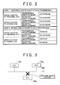
- the CPU 504 detects a faulty ECU on the basis of the transmission and reception error counter accumulated values input through the interface 502. For example, when an ECU enters a bus off state and interrupts data transmission and then returns from the bus off state after a predetermined period of time has elapsed, the transmission and reception error counter accumulated values of that ECU and the other ECUs vary as shown in FIG. 2 .
- the bus off state is classified into two cases.
- the first bus off state is due to a fault of the local ECU.
- the second bus off state is due to interruption of data transmission of the local ECU, caused by data transmitted from another faulty ECU, even when the local ECU is normal.
- CASE 1 corresponds to the first bus off state
- CASE 2 corresponds to the second bus off state.
- the transmission and reception error counter accumulated values of the bus-off ECU both do not increase, that is, both remain constant. This is because a faulty ECU itself is in a bus off state and interrupts data transmission.
- the transmission and reception error counter accumulated values of the other ECUs that is, the ECUs that normally operate, both do not increase, that is, both remain constant.
- the communication configuration of the CAN communication system is one-to-many communications, that is, communications from an ECU to the other ECUs.
- there are communications from a normal ECU that normally operates hereinafter, referred to as communications from a normal ECU
- communications from an abnormal ECU hereinafter, referred to as communications from an abnormal ECU. Because the abnormal ECU is in a bus off state and interrupts data transmission, the transmission error counter of the abnormal ECU does not increase.
- the transmission error counter of each normal ECU does not increase.
- the reception error counter of each normal ECU does not increase.
- the reception error counter of the abnormal ECU does not increase. In other words, because the abnormal ECU cannot carry out data reception, the reception error counter does not increase.
- the transmission error counter accumulated value of an abnormal ECU increases, and the reception error counter accumulated value thereof does not increase, that is, remains constant.
- the transmission and reception error counter accumulated values of a normal ECU, other than the bus-off ECU increase. This is because the abnormal ECU, which is not in a bus off state, continues to carry out communications and, therefore, the communications interferes with communications of the other ECU.
- the ECU which transmits data, monitors the CAN communication line 400 at the same time. The ECU determines a situation where a monitoring bit is different from the transmitted bit, as a transmission error.
- the abnormal ECU which is not in a bus off state, continues communications, data transmitted from the abnormal ECU are transmitted at an abnormal voltage. For this reason, the monitoring bit differs from the transmitted bit. Thus, the transmission error counter of the abnormal ECU increases. In addition, because the abnormal ECU cannot receive data transmitted from another normal ECU, the reception error counter does not increase. In the communications from a normal ECU to the abnormal ECU, at the transmission side, the monitoring bit is different from the transmitted bit due to the influence of the faulty ECU. Thus, the transmission error counter of the normal ECU increases. In addition, the data transmitted from a normal ECU cause a reception error in another normal ECU due to the influence of the abnormal ECU. Thus, the reception error counter of the normal ECU increases.
- the CPU 504 estimates that a communication line to that ECU is broken.
- the CPU 504 determines that a communication line to the bus-off ECU is broken.
- the CPU 504 determines that it is difficult to identify a fault point.
- a fault location method according to the present embodiment will be described.
- the case described below is such that, as shown in FIG. 3 , among the ECUs 100 1 to 100 3 connected to the CAN communication line 400, a one-wire break has occurred in a CAN communication line connected to the ECU 100 3 , and then the communication line is currently returned to a normal state.
- this may also be applied to the case in which the number of ECUs that constitute the CAN communication system is two, four or more.
- this may also be applied to the case in which two or more ECUs each are connected to a one-wire-broken communication line.
- the ECU 100 3 When a one-wire break has occurred in a CAN communication line connected to the ECU 100 3 , as shown in FIG. 4 , after the one-wire break has occurred in the CAN communication line connected to the ECU 100 3 , the ECU 100 3 enters a bus off state prior to the ECUs 100 1 and 100 2 . This is because a transmission error frequently occurs due to a one-wire break. After that, the ECU 100 1 and/or the ECU 100 2 enter a bus off state. This is because the data transmitted from the ECU 100 3 that is connected to a one-wire-broken CAN communication line before entering a bus off state influences communications of the ECU 100 1 and/or the ECU 100 2 .
- each ECU which serves as a communication device, changes into a bus off state on the basis of the detected transmission error.
- the ECU 100 1 and/or the ECU 100 2 might enter a bus off state prior to the ECU 100 3 .
- the ECU 100 1 and/or ECU 100 2 naturally initiate communications.
- the ECUs 100 1 to 100 3 repeatedly enter a bus off state and return from the bus off state, the ECU 100 3 is more likely to enter a bus off state. Under the above situation, detection of a fault point is performed on the basis of the transmission and reception error counter accumulated values.
- ECUs included in the communication system carry out communications.
- the ECUs included in the CAN communication system carry out communications.
- the CPU 102 3 of the ECU 100 3 determines whether a communication error is detected (step S502). For example, the CPU 102 3 of the ECU 100 3 monitors the condition of communications, and detects a transmission error and/or a reception error.
- the CPU 102 3 of the ECU 100 3 obtains the detection time and, in addition, adds the transmission error counter value corresponding to the transmission error and/or the reception error counter value corresponding to the reception error to obtain the transmission error counter accumulated value and/or the reception error counter accumulated value.
- the detection time, the transmission error counter accumulated value and/or the reception error counter accumulated value are stored in the storage unit 106 3 . It may be configured to store the transmission error counter value and/or the reception error counter value.
- the CPU 102 3 of the ECU 100 3 notifies the other ECUs that an error is detected in order to prevent the other ECUs acquire a message containing an error.
- step S502 NO
- the process returns to step S502 and continues to detect a communication error. In this case, the condition of communications is normal, and estimation of a fault point ends.
- the CPU 102 3 of the ECU 100 3 determines whether to enter a bus off state (step S504).
- the CPU 102 3 of the ECU 100 3 determines to enter a bus off state when the transmission error counter accumulated value is larger than or equal to a predetermined transmission error counter accumulated value at which it is assumed to influence communications of the other ECUs 100, and determines not to enter a bus off state when the transmission error counter accumulated value is smaller than the predetermined transmission error counter accumulated value.
- a predetermined transmission error counter accumulated value For example, when the CAN protocol is employed as the communication protocol of the in-vehicle LAN, it is determined to change into a bus off state when the transmission error counter accumulated value is larger than or equal to 256.
- the ECU that has changed into the bus off state resumes communications when a return condition is satisfied.
- the return condition includes the case in which any ECUs do not carry out communications for a predetermined period of time, for example, 2.5 ms.
- step S504 When it is determined that the ECU 100 3 is in a bus off state (step S504: YES), the CPU 102 3 of the ECU 100 3 interrupts data transmission. This interruption of data transmission continues for a predetermined period of time. Then, the CPU 102 3 of the ECU 100 3 stores the time, at which data transmission is interrupted, in the storage unit 106 3 . In this case, ECUs other than the ECU 100 3 are not notified that the ECU 100 3 is in a bus off state, so the other ECUs continue to carry out communications. On the other hand, when it is determined that the ECU 100 3 is not in a bus off state (step S504: NO), the process returns to step S502 and continues to detect a communication error.
- the duration of fault is short and, therefore, the ECU 100 3 does not change into a bus off state.
- the CPU 102 of each ECU 100 stores the detection time of the communication error in the storage unit 106.
- the CPU 102 of each ECU 100 on the basis of whether the communication error is a transmission error or a reception error, obtains a transmission error counter value and/or a reception error counter value, and adds the transmission error counter value and/or the reception error counter value to the transmission error counter accumulated value and/or the reception error counter accumulated value, and then stores the resultant transmission error counter accumulated value and/or the resultant reception error counter accumulated value in the storage unit 106 (step S508).
- an ECU that has detected a communication error transmits an error frame.
- the error frame is received by the other ECUs included in the CAN communication system.
- the ECUs, other than the ECU that has detected the communication error each increase the reception error counter accumulated value.
- the ECUs that have received the error frame increase only the reception error counter accumulated value and do not increase the transmission error counter accumulated value.
- An ECU whose transmission message causes an error increases the transmission error counter accumulated value.
- Each ECU stores the transmission error counter accumulated value, the reception error counter accumulated value, time at which the transmission error counter accumulated value varies, and time at which the reception error counter accumulated value varies, in the storage unit 106.
- it may be configured to store the transmission error counter value and/or the reception error counter value.
- the CPU 102 3 of the ECU 100 3 determines whether a predetermined period of time has elapsed since it enters a bus off state (step S510).
- the predetermined period of time may be set to a period of time that allows accumulation of some transmission and reception error counter values to make it possible to determine an abnormal ECU. For example, about several minutes may be set to the predetermined period of time.
- step S510: NO When it is determined that the predetermined period of time has not elapsed (step S510: NO), the process returns to step S508 and continues to detect a communication error. On the other hand, when it is determined that the predetermined period of time has elapsed (step S510: YES), the CPU 102 3 of the ECU 100 3 returns communications to a normal state. For example, data transmission is initiated.
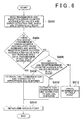
- the process of the fault location device 500 will be described with reference to FIG. 6 .
- the fault location device 500 is connected to the CAN communication system 1000 through the DLC 450.
- the CPU 504 reads the transmission and reception error counter accumulated values, stored in the storage units 106 of all the ECUs, and the error detection time (step S602).
- the CPU 504 determines whether there is an ECU whose transmission error counter accumulated value increases and whose reception error counter accumulated value does not increase while data transmission of the ECU 100 3 is interrupted, that is, while the ECU 100 3 is in a bus off state (step S604).
- step S604 the CPU 504 estimates that a communication line to the appropriate ECU is broken (step S606). Because an ECU connected to a one-wire-broken communication line is not able to detect that a message is transmitted from the other ECUs, the transmission error counter accumulated value increases, whereas the reception error counter accumulated value does not increase, while the ECU 100 3 is in a bus off state. Thus, when such an ECU is present, it may be estimated that a communication line to that ECU is broken.
- step S604 determines whether no transmission and reception error counter values increase in all the ECUs (step 608).
- step S608: NO the CPU 504 estimates that a communication line to the ECU 100 3 is broken (step S610). That is, when no communication error occurs while the ECU 100 3 is in a bus off state, it may be estimated that a communication line to the ECU 100 3 is broken.
- step S612 the CPU 504 determines that it is difficult to estimate a fault point, and cancels determination of the fault location (step S612). In this case, it is assumed that the ECU 100 3 returns from a bus off state to a normal state for a short period of time or a designed period of time during which the ECU 100 3 changes into a bus off state is short.
- the wire-broken point is repaired (step S614).
- the configuration of the CAN communication system according to the second embodiment is similar to the configuration described with reference to FIG. 1 .
- the CPU 504 estimates that a communication line to that ECU is broken.
- the CPU 504 determines that a communication line to the bus-off ECU is broken.
- the CPU 504 determines that it is difficult to identify a fault location. That is, when the transmission error counter accumulated values recorded in all the ECUs do not increase and the receiption error counter accumulated values recorded in all the ECUs increase, the CPU 504 determines that it is difficult to identify a fault location.
- the CPU 504 determines that it is difficult to identify a fault point. That is, when the transmission and reception error counter accumulated values recorded in all the ECUs increase, the CPU 504 determines that it is difficult to identify a fault point.
- a fault location method according to the present embodiment will be described.
- the process at each ECU is similar to the process described with reference to FIG. 5 .
- the process of the fault location device 500 will be described with reference to FIG. 7 .
- the fault location device 500 is connected to the CAN communication system 1000 through the DLC 450.
- the CPU 504 reads the transmission and reception error counter accumulated values, stored in the storage units 106 of all the ECUs, and the error detection time (step S702).
- the CPU 504 checks for each ECU whether the transmission error counter accumulated value and/or the reception error counter accumulated value increase (step S704).
- the CPU 504 determines whether there is an ECU whose transmission error counter accumulated value increases while data transmission of the ECU 100 3 is interrupted, that is, while the ECU 100 3 is in a bus off state (step S706).
- step S706 When there is an ECU whose transmission error counter accumulated value increases while data transmission of the ECU 100 3 is interrupted (step S706: YES), the CPU 504 determines whether there is an ECU whose reception error counter accumulated value does not increase while data transmission of the ECU 100 3 is interrupted (step S708).
- step S708 When the appropriate ECU is present (step S708: YES), the CPU 504 estimates that a communication line to the appropriate ECU is broken (step S710).
- step S706 when there is no ECU whose transmission error counter accumulated value increases while data transmission of the ECU 100 3 is interrupted (step S706: NO), the CPU 504 determines whether there is an ECU whose reception error counter accumulated value does not increase while data transmission of the ECU 100 3 is interrupted (step S712).
- step S712 When there is an ECU whose reception error counter accumulated value does not increase while data transmission of the ECU 100 3 is interrupted (step S712: YES), the CPU 504 determines whether no reception error counter accumulated values of all the ECUs increase (step S714).
- step S714 NO
- the CPU 504 determines that a communication line to the ECU 100 3 is broken (step S716).
- step S712 when, in step S712, there is no ECU whose reception error counter accumulated value does not increase while data transmission of the ECU 100 3 is interrupted (step S712: NO), when, in step S708, there is no appropriate ECU (step S708: NO), or when, in step S714, there is an ECU whose reception error counter accumulated value increases (step S714: YES), the CPU 504 determines that it is difficult to identify a fault point and cancels the detection of a fault point (step S718). In this case, it is assumed that the ECU 100 3 returns from a bus off state to a normal state for a short period of time or a designed period of time during which the ECU 100 3 changes into a bus off state is short.
- a CAN communication system according to a third embodiment of the invention will be described.
- the configuration of the CAN communication system according to the third embodiment differs from the above described embodiments in that, as shown in FIG. 8 , the functions of the fault location device that identifies a fault point are incorporated into the ECU.
- This ECU may be configured as a master ECU.
- the CPU 102 2 and CPU 102 3 of the other ECUs 100 2 and 100 3 when communications returns to a normal state, transmit the transmission and reception error counter accumulated values and the error detection time to the ECU 100 1 through the CAN communication line 400.
- the transmission timing may be a regular transmission timing of each ECU or the transmission may be performed so that the ECU 100 1 inquires the transmission of each ECU and then the ECU that has received the inquiry responds to the inquiry.
- the ECU 100 1 estimates an ECU, which is connected to a one-wire broken communication line, by a method similar to the above described method on the basis of the transmission and reception error counter accumulated values and the error detection time, transmitted from the other ECUs.
- the CPU 102 1 of the ECU 100 1 records the estimated ECU in the storage unit 106.
- a fault location method according to the third embodiment will be described.
- the process at each ECU is similar to the process described with reference to FIG. 5 .
- the process of the master ECU 100 1 further includes the process described with reference to FIG. 6 or FIG. 7 in addition to the process described with reference to FIG. 5 .
- the information regarding the estimated ECU may be displayed on the screen of a meter or a navigation system. By so doing, without any extra reading device, it is possible to indicate the estimated fault point.
- the CPUs 102 2 and 102 3 of the other ECUs 100 2 and 100 3 transmit the transmission and reception error counter accumulated values and the error detection time to the ECU 100 1 through the CAN communication line 400 when communications returns to a normal state.
- an exclusive line connected to the ECU 100 1 is provided and the transmission and reception error counter accumulated values and the error detection time are transmitted through the exclusive line.
- a fault location device detects a communication device connected to a broken communication line from among communication devices that carry out communications between each other through a two-wire communication line.
- the communication device when detecting a communication error, stores communication error time and a communication error counter accumulated value indicating accumulated counts of the communication error, changes into a bus off state on the basis of the communication error counter accumulated value, and, after a predetermined period of time, returns from the bus off state.
- the fault location device (500) includes an acquisition unit (502) that acquires the communication error time and communication error counter accumulated value, stored in each communication device; and a detection unit (504) that detects a communication device connected to a broken communication line on the basis of variations in the communication error counter accumulated values while any one of the communication devices (100) is in a bus off state.
Landscapes
- Engineering & Computer Science (AREA)
- Environmental & Geological Engineering (AREA)
- Computer Networks & Wireless Communication (AREA)
- Signal Processing (AREA)
- Small-Scale Networks (AREA)
Abstract
Description
- The invention relates to a controller area network (CAN) communication system and method by which communications are carried out among a plurality of communication devices connected through a CAN bus and, more particularly, to a fault location device, communication device, and fault location method that are able to identify a fault point due to a one-wire break.
- A known CAN communication system carries out data communications among a plurality of communication devices. The plurality of communication devices are connected with one another through a CAN bus, and each have a CAN controller unit. The CAN communication protocol allows bidirectional serial communication through a differential serial bus.
- In the CAN communication system, each communication device transmits data with its own identification (ID) code to the CAN bus. At the time the communication device transmits the data, when the CAN bus is not occupied by data transmitted from another communication device, the data transmitted from the communication device flows through the CAN bus and reaches an intended communication device. On the other hand, when the CAN bus is occupied by data from another communication device, the data, which will be transmitted from the communication device, is queued in the CAN controller unit. Then, when there is only one communication device in which the data are queued, the queued data flow through the CAN bus when the CAN bus is unoccupied. On the other hand, when there are a plurality of communication devices in which the data are queued, the data of the highest-priority communication device on the basis of the ID code from among those communication devices flow through the CAN bus prior to the other queued data.
- The CAN communication system includes the plurality of communication devices (nodes). These plurality of communication devices are connected with one another through the CAN bus which is formed of twisted pair wires. The communication devices transmit and receive data to and from one another. The twisted pair wires of the CAN bus are bus wires, one of which is called CAN High (CANH) and the other one of which is called CAN Low (CANL). The communication devices may be, for example, formed of a plurality of electronic control units (ECUs) that control various portions of a vehicle.
- Japanese Patent Application Publication No.
2003-143164 JP-A-2003-143164 - However, the above described related art has the following problems.
- In the CAN communication system, when a one-wire break occurs, it is difficult to identify a communication device connected to a communication line in which the one-wire break is occurring. The one-wire break includes a break that occurs in one of communication lines connected to a communication device and a contact failure that occurs in one of the communication lines connected to a communication device. When the one-wire break occurs, it is no problem when the one-wire break continues and then can be repaired; however, there is a possibility that, for example, in the case of a contact failure, the communication line may be apparently connected before the one-wire break is repaired. In this case, the communication line is just apparently connected, so a contact failure occurs again when the communication line is pulled. Thus, a fault point may be identified by pulling the communication line. However, because a vehicle is equipped with several hundreds of communication lines, it is practically impossible to identify the communication device, in which the contact failure is occurring, by pulling the communication lines.
- In addition, when a one-side communication line is broken, a communication device connected to the broken communication line generates an abnormal voltage. This corrupts data transmitted from another communication device. As a result, data (message) from a normal communication device are also corrupted. As a consequence of corruption of the message transmitted from the normal communication device, the normal communicable communication device is also determined to be in a breakdown of communications. Thus, the normal communicable communication device is erroneously determined to be faulty.
- In the above described
JP-A-2003-143164 - The invention provides a fault location device, communication device, and fault location method that are able to detect a communication device in which one of two wires connected to the communication device is broken.
- A first aspect of the invention provides a fault location device. The fault location device detects a communication device connected to a broken communication line from among first and second communication devices that carry out communications between each other through a two-wire communication line. When a communication error has been detected, each of the communication devices stores time of the communication error and a communication error counter accumulated value that indicates accumulated counts corresponding to the communication error, changes into a bus off state on the basis of the communication error counter accumulated value and then, after a predetermined period of time has elapsed, returns from the bus off state. The fault location device includes: an acquisition unit that acquires the time of the communication error and the communication error counter accumulated value, which are stored in each of the communication devices; and a detection unit that detects a communication device connected to a broken communication line on the basis of variations in the communication error counter accumulated values while any one of the communication devices is in a bus off state.
- With the above configuration, it is possible to detect a communication device connected to a broken communication line on the basis of variations in the communication error counter accumulated values while any one of the communication devices is in a bus off state. The fault location device may be, for example, formed of a service tool.
- In the above first aspect, the communication error may include a transmission error and a reception error. Each of the communication devices may store a transmission error counter accumulated value that indicates accumulated counts corresponding to the transmission error and a reception error counter accumulated value that indicates accumulated counts corresponding to the reception error. When there is a communication device whose transmission error counter accumulated value increases and whose reception error counter accumulated value does not increase, the detection unit may determine that a communication line connected to that communication device is broken.
- Alternatively, in the first aspect, the communication error may include a transmission error and a reception error. Each of the communication devices may store a transmission error counter accumulated value that indicates accumulated counts corresponding to the transmission error and a reception error counter accumulated value that indicates accumulated counts corresponding to the reception error. When there is no communication device whose transmission error counter accumulated value increases, and when the reception error counter accumulated values of all the communication devices do not increase, the detection unit may determine that a communication line connected to the communication device which is in the bus off state is broken.
- With the above configuration, it is possible to detect a communication device connected to a broken communication line on the basis of the transmission error counter accumulated value and the reception error counter accumulated value, which are stored in each of the communication devices.
- A second aspect of the invention provides a first communication device in a communication system formed of the first communication device and a second communication device. The first communication device and the second communication device carry out communications between each other through a two-wire communication line. The first communication device includes: a storage unit that stores time of a communication error and a communication error counter accumulated value that indicates accumulated counts corresponding to the communication error; a control unit that changes the first communication device into a bus off state on the basis of the communication error counter accumulated value and then, after a predetermined period of time has elapsed, returns the first communication device from the bus off state; an acquisition unit that acquires the time of the communication error and the communication error counter accumulated value, which are stored in each of the communication devices; and a detection unit that detects a communication device connected to a broken communication line on the basis of variations in the communication error counter accumulated values while one of the first and second communication devices is in a bus off state.
- With the above configuration, it is possible to detect a communication device connected to a broken communication line on the basis of variations in the communication error counter accumulated values while one of the first and second communication devices is in a bus off state. The first communication device may be formed of a communication device that has, for example, a master function.
- In the above second aspect, the communication error may include a transmission error and a reception error. The storage unit may store a transmission error counter accumulated value that indicates accumulated counts corresponding to the transmission error and a reception error counter accumulated value that indicates accumulated counts corresponding to the reception error. When there is a communication device whose transmission error counter accumulated value increases and whose reception error counter accumulated value does not increase, the detection unit may determine that a communication line connected to that communication device is broken.
- Alternatively, in the second aspect, the communication error may include a transmission error and a reception error. The storage unit may store a transmission error counter accumulated value that indicates accumulated counts corresponding to the transmission error and a reception error counter accumulated value that indicates accumulated counts corresponding to the reception error. When there is no communication device whose transmission error counter accumulated value increases, and when the reception error counter accumulated values of all the communication devices do not increase, the detection unit may determine that a communication line connected to the communication device which has been in the bus off state is broken.
- With the above configuration, it is possible to detect a communication device connected to a broken communication line on the basis of the transmission error counter accumulated value and the reception error counter accumulated value, which are stored in each of the communication devices.
- A third aspect of the invention provides a fault location method for detecting a communication device connected to a broken communication line from among first and second communication devices that carry out communications between each other through a two-wire communication line. The fault location method includes: when a communication error has been detected by the first communication device, storing time of the communication error and a communication error counter accumulated value that indicates accumulated counts corresponding to the communication error; changing the first communication device into a bus off state on the basis of the communication error counter accumulated value and then, after a predetermined period of time has elapsed, returning the first communication device from the bus off state; acquiring the time of the communication error and the communication error counter accumulated value, which are stored in each of the first and second communication devices; and detecting a communication device connected to a broken communication line on the basis of variations in the communication error counter accumulated values of each of the communication devices while one of the first and second communication devices is in a bus off state.
- By so doing, it is possible to detect a communication device connected to a broken communication line on the basis of variations in the communication error counter accumulated values while one of the first and second communication devices is in a bus off state. The fault location method may be, for example, executed by a service tool.
- In the above third aspect, the communication error may include a transmission error and a reception error. When the time of the communication error and the communication error counter accumulated value are stored, a transmission error counter accumulated value that indicates accumulated counts corresponding to the transmission error and a reception error counter accumulated value that indicates accumulated counts corresponding to the reception error may be stored. When there is a communication device whose transmission error counter accumulated value increases and whose reception error counter accumulated value does not increase, it may be determined that a communication line connected to that communication device is broken.
- Alternatively, in the third aspect, the communication error may include a transmission error and a reception error. When the time of the communication error and the communication error counter accumulated value are stored, a transmission error counter accumulated value that indicates accumulated counts corresponding to the transmission error and a reception error counter accumulated value that indicates accumulated counts corresponding to the reception error may be stored. When there is no communication device whose transmission error counter accumulated value increases and when the reception error counter accumulated values of all the communication devices do not increase, it may be determined that a communication line connected to the communication device which is in the bus off state is broken.
- By so doing, it is possible to detect a communication device connected to a broken communication line on the basis of the transmission error counter accumulated value and the reception error counter accumulated value, which are stored in each of the communication devices.
- According to the above described fault location device, communication device and fault location method, it is possible to detect a communication device in which one of two wires connected to the communication device is broken.
- The features, advantages, and technical and industrial significance of this invention will be described in the following detailed description of example embodiments of the invention with reference to the accompanying drawings, in which like numerals denote like elements, and wherein:
-
FIG. 1 is a view that illustrates a CAN communication system and a fault location device according to a first embodiment of the invention; -
FIG. 2 is a view that illustrates an example of a time variation in reception and transmission error counter accumulated values under the condition that there is a communication device that is in a bus off state; -
FIG. 3 is a view that illustrates the CAN communication system according to the first embodiment of the invention; -
FIG. 4 is a time chart that shows a change into a bus off state of each communication device under the condition that there is a faulty communication device; -
FIG. 5 is a flowchart that shows the operations of a communication device according to the first embodiment of the invention; -
FIG. 6 is a flowchart that shows the operations of the fault location device according to the first embodiment of the invention; -
FIG .7 is a flowchart that shows the operations of the fault location device according to a second embodiment of the invention; and -
FIG. 8 is a view that illustrates the CAN communication system according to a third embodiment of the invention. - Embodiments of the invention will now be described with reference to the accompanying drawings. Note that in all the drawings for illustrating the embodiments, like reference numerals denote like components, and the description thereof will not be repeated.
- A CAN communication system according to a first embodiment of the invention will be described with reference to
FIG. 1. FIG. 1 also shows aDLC 450 and afault location device 500. TheDLC 450 and thefault location device 500 are connected to the CAN communication system when a fault point is detected. - The
CAN communication system 1000 according to the present embodiment, for example, includes a plurality of communication devices that carry out communications in accordance with the communication protocol of an in-vehicle LAN. For example, the communication protocol of the in-vehicle LAN may employ a controller area network (CAN). The communication devices are respectively formed of a plurality of electronic control units (ECUs) that control various portions of a vehicle. - In the CAN, as described above, a communication line (communication bus) uses a two-wire
CAN communication line 400 formed of aCANH 200 and aCANL 300, and a terminator is connected at each end of the two-wireCAN communication line 400. Then, in the CAN, a transmitting communication device transmits inverted signals to theCANH 200 and theCANL 300, and a receiving communication device determines, on the basis of a voltage difference between theCANH 200 and theCANL 300, whether a piece of data on theCAN communication line 400 is "1" or "0". - Each of the
ECUs 1001 to 1003 includes a CPU 102 (1021, 1022, and 1023), a communication driver 104 (1041, 1042, and 1043), and a storage unit 106 (1061, 1062, and 1063). Each CPU 102 executes a control process for controlling various portions of the vehicle and a process for carrying out communications with another ECU. Each communication driver 104 is connected to the above described two-wireCAN communication line 400. Each communication driver 104 outputs transmission data, transferred from the CPU 102, to the two-wireCAN communication line 400, and inputs data on the two-wireCAN communication line 400 into the CPU 102. Each storage unit 106 stores a communication error detected by the CPU 102. The communication error includes a transmission error and a reception error. - Each communication driver 104 includes first and second output buffers (two output buffers) and a binarization circuit. For example, the first output buffer sets the voltage of the
CANH 200 to a high level (for example, 3.5 V) when the transmission data is "0", or sets the voltage of theCANH 200 to a low level (for example, 2.5 V) when the transmission data is "1". The second output buffer sets the voltage of theCANL 300 to a low level (for example, 1.5 V) when the transmission data is "0", or sets the voltage of theCANL 300 to a high level (for example, 2.5 V) when the transmission data is "1". The binarization circuit generates a binary signal "1" or "0" that indicates the data on theCAN communication line 400 on the basis of a difference between a voltage input to theCANH 200 and a voltage input to theCANL 300. - In each of the
ECUs 1001 to 1003, the CPU 102 monitors the condition of CAN communication and detects a communication error. For example, the CPU 102 monitors the condition of CAN communication and detects a reception error and/or a transmission error as the communication error. The communication error includes any one of a bit error, a stuff error, a cyclic redundancy check (CRC) error, a form error, and an authentication error. The communication device, which transmits data, monitors the bus at the same time. The bit error is detected when a monitoring bit is different from a transmitted bit. The stuff error is detected when successive six bits have the same bit level against a bit-stuffing rule. A CRC sequence contains a CRC calculation result calculated in a transmitter. The CRC error is detected when a receiver calculates a CRC and the calculated CRC is different from the above CRC calculation result. The form error is detected when a field whose number of bits is fixed contains an invalid bit. The authentication error is detected by the transmitter when an ACK slot from a receiver does not return a dominant bit. - The CPU 102 updates an error counter value, which is determined beforehand in correspondence with a communication error, in accordance with the detected communication error. For example, the CPU 102 detects a transmission error and/or a reception error, increases a transmission error counter value (TEC), corresponding to the transmission error, and/or a reception error counter value (REC), corresponding to the reception error, and then obtains a transmission error counter accumulated value and/or a reception error counter accumulated value. The transmission error counter accumulated value represents accumulated counts corresponding to the transmission error. The reception error counter accumulated value represents accumulated counts corresponding to the reception error. Then, the CPU 102 determines to enter a state called bus off when the transmission error counter accumulated value is larger than or equal to a predetermined transmission error counter accumulated value at which it is assumed to influence communications of the
other ECUs 100. The bus off is a function by which the communication device interrupts data transmission by itself and isolates itself from the bus when the number of transmission errors is larger than or equal to a prescribed number of counts and then, after it is confirmed that the bus idle state continues for a predetermined period of time, returns to a normal state. In this bus off state, data reception is allowed. When an ECU connected to a one-wire-broken communication line enters a bus off state, no abnormal voltage is transmitted from the one-wire-broken ECU and, therefore, the other ECUs are not adversely influenced. Thus, it is possible to allow communications among the other ECUs. In addition, each of the CPUs 102 of the other ECUs monitors the condition of communications of the local ECU. Specifically, the CPU 102 of each ECU records communication errors. More specifically, the CPU 102 records a variation in transmission error counter value in the storage unit 106. For example, when the CPU 102 detects a communication error, the CPU 102 records a detection time at which the communication error is detected, and adds an error counter value, corresponding to the transmission error and/or the reception error and included in the communication error, to the transmission error counter accumulated value and/or the reception error counter accumulated value. In addition, the CPU 102 initiates communications after a predetermined period of time has elapsed since the CPU 102 enters a bus off state. - The fault location device according to the embodiment of the invention will be described.
- The
fault location device 500 according to the present embodiment is connected to theCAN communication system 1000 through the data link connector (DLC) 450. The fault location device may be formed of an external fault determination tool. The fault determination tool includes a diagnostic tool of a service department. Thefault location device 500 includes an interface (I/F) 502 and aCPU 504. TheCPU 504 serves as an acquisition unit and a detection unit. - The
interface 502 receives the detection time of each of the transmission and reception errors and the transmission and reception error counter accumulated values, which are stored in the storage unit 106 of eachECU 100. The detection time of each of the transmission and reception errors and the transmission and reception error counter accumulated values are input to theCPU 504. - The
CPU 504 detects a faulty ECU on the basis of the transmission and reception error counter accumulated values input through theinterface 502. For example, when an ECU enters a bus off state and interrupts data transmission and then returns from the bus off state after a predetermined period of time has elapsed, the transmission and reception error counter accumulated values of that ECU and the other ECUs vary as shown inFIG. 2 . - The bus off state is classified into two cases. The first bus off state is due to a fault of the local ECU. The second bus off state is due to interruption of data transmission of the local ECU, caused by data transmitted from another faulty ECU, even when the local ECU is normal. As shown in
FIG. 2 ,CASE 1 corresponds to the first bus off state, andCASE 2 corresponds to the second bus off state. - According to
FIG. 2 , when a broken communication line is connected to an ECU that enters a bus off state, the transmission and reception error counter accumulated values of the bus-off ECU both do not increase, that is, both remain constant. This is because a faulty ECU itself is in a bus off state and interrupts data transmission. In addition, when a broken communication line is connected to an ECU that enters a bus off state, the transmission and reception error counter accumulated values of the other ECUs, that is, the ECUs that normally operate, both do not increase, that is, both remain constant. This is because the ECU connected to a broken communication line is in a bus off state and interrupts data transmission and, therefore, the other normal ECUs are not influenced by the faulty ECU and are able to carry out communications as if there were no faulty ECU. The communication configuration of the CAN communication system is one-to-many communications, that is, communications from an ECU to the other ECUs. Here, there are communications from a normal ECU that normally operates (hereinafter, referred to as communications from a normal ECU) and communications from an ECU connected to a broken communication line (hereinafter, referred to as communications from an abnormal ECU). Because the abnormal ECU is in a bus off state and interrupts data transmission, the transmission error counter of the abnormal ECU does not increase. Because data transmitted from a normal ECU are received by another normal ECU, the transmission error counter of each normal ECU does not increase. In addition, because a normal ECU is able to receive data transmitted from another normal ECU, the reception error counter of each normal ECU does not increase. In addition, because data transmitted from a normal ECU are not received by the abnormal ECU, the reception error counter of the abnormal ECU does not increase. In other words, because the abnormal ECU cannot carry out data reception, the reception error counter does not increase. - When a normal ECU enters a bus off state, the transmission error counter accumulated value of an abnormal ECU, which is not in a bus off state, increases, and the reception error counter accumulated value thereof does not increase, that is, remains constant. In addition, the transmission and reception error counter accumulated values of a normal ECU, other than the bus-off ECU, increase. This is because the abnormal ECU, which is not in a bus off state, continues to carry out communications and, therefore, the communications interferes with communications of the other ECU. In the CAN communication, the ECU, which transmits data, monitors the
CAN communication line 400 at the same time. The ECU determines a situation where a monitoring bit is different from the transmitted bit, as a transmission error. Because the abnormal ECU, which is not in a bus off state, continues communications, data transmitted from the abnormal ECU are transmitted at an abnormal voltage. For this reason, the monitoring bit differs from the transmitted bit. Thus, the transmission error counter of the abnormal ECU increases. In addition, because the abnormal ECU cannot receive data transmitted from another normal ECU, the reception error counter does not increase. In the communications from a normal ECU to the abnormal ECU, at the transmission side, the monitoring bit is different from the transmitted bit due to the influence of the faulty ECU. Thus, the transmission error counter of the normal ECU increases. In addition, the data transmitted from a normal ECU cause a reception error in another normal ECU due to the influence of the abnormal ECU. Thus, the reception error counter of the normal ECU increases. - On the basis of the transmission and reception error counter accumulated values stored in the storage units 106 of all the
ECUs 100, while an ECU is in a bus off state, when there is an ECU whose transmission error counter accumulated value increases and whose reception error counter accumulated value does not increase, theCPU 504 estimates that a communication line to that ECU is broken. - In addition, on the basis of the transmission and reception error counter accumulated values stored in the storage units 106 of all the
ECUs 100, while an ECU is in a bus off state, when there is no ECU whose transmission error counter accumulated value increases and whose reception error counter accumulated value does not increase, and when the reception error counter accumulated values stored in the storage units 106 of all theECUs 100 do not increase, theCPU 504 determines that a communication line to the bus-off ECU is broken. - In addition, on the basis of the transmission and reception error counter accumulated values recorded in all the ECUs, while an ECU is in a bus off state, when there is no ECU whose transmission error counter accumulated value increases and whose reception error counter accumulated value does not increase, and when the transmission and reception error counter accumulated values recorded in all the ECUs increase, the
CPU 504 determines that it is difficult to identify a fault point. - A fault location method according to the present embodiment will be described.
- In the present embodiment, the case described below is such that, as shown in
FIG. 3 , among theECUs 1001 to 1003 connected to theCAN communication line 400, a one-wire break has occurred in a CAN communication line connected to theECU 1003, and then the communication line is currently returned to a normal state. However, this may also be applied to the case in which the number of ECUs that constitute the CAN communication system is two, four or more. In addition, this may also be applied to the case in which two or more ECUs each are connected to a one-wire-broken communication line. - When a one-wire break has occurred in a CAN communication line connected to the
ECU 1003, as shown inFIG. 4 , after the one-wire break has occurred in the CAN communication line connected to theECU 1003, theECU 1003 enters a bus off state prior to theECUs ECU 1001 and/or theECU 1002 enter a bus off state. This is because the data transmitted from theECU 1003 that is connected to a one-wire-broken CAN communication line before entering a bus off state influences communications of theECU 1001 and/or theECU 1002. In the fault location method according to the present embodiment, on the basis of the transmission errors and reception errors detected during times since theECU 1003 connected to a one-wire-broken CAN communication line enters a bus off state until thenormal ECUs 1001 and/or 1002 enter a bus off state, detection of a fault point, that is, detection of a broken point, is performed. As described above, each ECU, which serves as a communication device, changes into a bus off state on the basis of the detected transmission error. - Here, the
ECU 1001 and/or theECU 1002 might enter a bus off state prior to theECU 1003. In this case, after the bus-offECU 1001 and/orECU 1002 return from the bus off state, theECU 1001 and/orECU 1002 naturally initiate communications. However, while theECUs 1001 to 1003 repeatedly enter a bus off state and return from the bus off state, theECU 1003 is more likely to enter a bus off state. Under the above situation, detection of a fault point is performed on the basis of the transmission and reception error counter accumulated values. - In addition, in the present embodiment, the process at each ECU and the process of the
fault location device 500 will be separately described. - The process at each ECU will be described with reference to
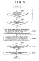
FIG. 5 . - In accordance with the communication protocol of the in-vehicle LAN, ECUs included in the communication system carry out communications. For example, in accordance with the CAN protocol, the ECUs included in the CAN communication system carry out communications.
- The CPU 1023 of the
ECU 1003 determines whether a communication error is detected (step S502). For example, the CPU 1023 of theECU 1003 monitors the condition of communications, and detects a transmission error and/or a reception error. - When the communication error is detected (step S502: YES), the CPU 1023 of the
ECU 1003 obtains the detection time and, in addition, adds the transmission error counter value corresponding to the transmission error and/or the reception error counter value corresponding to the reception error to obtain the transmission error counter accumulated value and/or the reception error counter accumulated value. The detection time, the transmission error counter accumulated value and/or the reception error counter accumulated value are stored in the storage unit 1063. It may be configured to store the transmission error counter value and/or the reception error counter value. Then, the CPU 1023 of theECU 1003 notifies the other ECUs that an error is detected in order to prevent the other ECUs acquire a message containing an error. For example, the CPU 1023 transmits an error flag. On the other hand, when no communication error is detected (step S502: NO), the process returns to step S502 and continues to detect a communication error. In this case, the condition of communications is normal, and estimation of a fault point ends. - The CPU 1023 of the
ECU 1003 determines whether to enter a bus off state (step S504). The CPU 1023 of theECU 1003 determines to enter a bus off state when the transmission error counter accumulated value is larger than or equal to a predetermined transmission error counter accumulated value at which it is assumed to influence communications of theother ECUs 100, and determines not to enter a bus off state when the transmission error counter accumulated value is smaller than the predetermined transmission error counter accumulated value. For example, when the CAN protocol is employed as the communication protocol of the in-vehicle LAN, it is determined to change into a bus off state when the transmission error counter accumulated value is larger than or equal to 256. The ECU that has changed into the bus off state resumes communications when a return condition is satisfied. The return condition includes the case in which any ECUs do not carry out communications for a predetermined period of time, for example, 2.5 ms. - When it is determined that the
ECU 1003 is in a bus off state (step S504: YES), the CPU 1023 of theECU 1003 interrupts data transmission. This interruption of data transmission continues for a predetermined period of time. Then, the CPU 1023 of theECU 1003 stores the time, at which data transmission is interrupted, in the storage unit 1063. In this case, ECUs other than theECU 1003 are not notified that theECU 1003 is in a bus off state, so the other ECUs continue to carry out communications. On the other hand, when it is determined that theECU 1003 is not in a bus off state (step S504: NO), the process returns to step S502 and continues to detect a communication error. In this case, the duration of fault is short and, therefore, theECU 1003 does not change into a bus off state. When the CPU 102 of eachECU 100 is detected a communication error, the CPU 102 stores the detection time of the communication error in the storage unit 106. In addition, the CPU 102 of eachECU 100, on the basis of whether the communication error is a transmission error or a reception error, obtains a transmission error counter value and/or a reception error counter value, and adds the transmission error counter value and/or the reception error counter value to the transmission error counter accumulated value and/or the reception error counter accumulated value, and then stores the resultant transmission error counter accumulated value and/or the resultant reception error counter accumulated value in the storage unit 106 (step S508). For example, an ECU that has detected a communication error (reception error) transmits an error frame. The error frame is received by the other ECUs included in the CAN communication system. As a result, the ECUs, other than the ECU that has detected the communication error, each increase the reception error counter accumulated value. The ECUs that have received the error frame increase only the reception error counter accumulated value and do not increase the transmission error counter accumulated value. An ECU whose transmission message causes an error increases the transmission error counter accumulated value. Each ECU stores the transmission error counter accumulated value, the reception error counter accumulated value, time at which the transmission error counter accumulated value varies, and time at which the reception error counter accumulated value varies, in the storage unit 106. In addition, it may be configured to store the transmission error counter value and/or the reception error counter value. - The CPU 1023 of the
ECU 1003 determines whether a predetermined period of time has elapsed since it enters a bus off state (step S510). For example, the predetermined period of time may be set to a period of time that allows accumulation of some transmission and reception error counter values to make it possible to determine an abnormal ECU. For example, about several minutes may be set to the predetermined period of time. - When it is determined that the predetermined period of time has not elapsed (step S510: NO), the process returns to step S508 and continues to detect a communication error. On the other hand, when it is determined that the predetermined period of time has elapsed (step S510: YES), the CPU 1023 of the
ECU 1003 returns communications to a normal state. For example, data transmission is initiated. - The process of the
fault location device 500 will be described with reference toFIG. 6 . Thefault location device 500 is connected to theCAN communication system 1000 through theDLC 450. - The
CPU 504 reads the transmission and reception error counter accumulated values, stored in the storage units 106 of all the ECUs, and the error detection time (step S602). - The
CPU 504 determines whether there is an ECU whose transmission error counter accumulated value increases and whose reception error counter accumulated value does not increase while data transmission of theECU 1003 is interrupted, that is, while theECU 1003 is in a bus off state (step S604). - When the appropriate ECU is present (step S604: YES), the
CPU 504 estimates that a communication line to the appropriate ECU is broken (step S606). Because an ECU connected to a one-wire-broken communication line is not able to detect that a message is transmitted from the other ECUs, the transmission error counter accumulated value increases, whereas the reception error counter accumulated value does not increase, while theECU 1003 is in a bus off state. Thus, when such an ECU is present, it may be estimated that a communication line to that ECU is broken. - On the other hand, when there is no appropriate ECU (step S604: NO), the
CPU 504 determines whether no transmission and reception error counter values increase in all the ECUs (step 608). When no transmission and reception error counter values increase in all the ECUs (step S608: NO), theCPU 504 estimates that a communication line to theECU 1003 is broken (step S610). That is, when no communication error occurs while theECU 1003 is in a bus off state, it may be estimated that a communication line to theECU 1003 is broken. On the other hand, when there is an ECU whose transmission or reception error counter value increases (step S608: YES), theCPU 504 determines that it is difficult to estimate a fault point, and cancels determination of the fault location (step S612). In this case, it is assumed that theECU 1003 returns from a bus off state to a normal state for a short period of time or a designed period of time during which theECU 1003 changes into a bus off state is short. - The wire-broken point is repaired (step S614).
- According to the present embodiment, even when a one-wire break had occurred in the CAN communication line in the past and the CAN communication line is currently returned to a normal state, it is possible to identify a wire-broken point.
- A CAN communication system according to a second embodiment of the invention will be described.
- The configuration of the CAN communication system according to the second embodiment is similar to the configuration described with reference to
FIG. 1 . - In the
fault location device 500 according to the second embodiment, on the basis of the transmission and reception error counter accumulated values recorded in all the ECUs, while an ECU is in a bus off state, when there is an ECU whose transmission error counter accumulated value increases and whose reception error counter accumulated value does not increase, theCPU 504 estimates that a communication line to that ECU is broken. - In addition, on the basis of the transmission and reception error counter accumulated values recorded in all the ECUs, while an ECU is in a bus off state, when there is an ECU whose transmission error counter accumulated value does not increase and whose reception error counter accumulated value does not increase, and when the transmission and reception error counter accumulated values recorded in all the ECUs do not increase, the
CPU 504 determines that a communication line to the bus-off ECU is broken. - In addition, on the basis of the transmission and reception error counter accumulated values recorded in all the ECUs, while an ECU is in a bus off state, when there is no ECU whose transmission error counter accumulated value increases and there is no ECU whose reception error counter accumulated value does not increase, the
CPU 504 determines that it is difficult to identify a fault location. That is, when the transmission error counter accumulated values recorded in all the ECUs do not increase and the receiption error counter accumulated values recorded in all the ECUs increase, theCPU 504 determines that it is difficult to identify a fault location. - In addition, on the basis of the transmission and reception error counter accumulated values recorded in all the ECUs, while an ECU is in a bus off state, when there is no ECU whose transmission error counter accumulated value does not increase and there is no ECU whose reception error counter accumulated value does not increase, the
CPU 504 determines that it is difficult to identify a fault point. That is, when the transmission and reception error counter accumulated values recorded in all the ECUs increase, theCPU 504 determines that it is difficult to identify a fault point. - A fault location method according to the present embodiment will be described.
- In the present embodiment, the case similar to the above described embodiment will be described.
- The process at each ECU is similar to the process described with reference to
FIG. 5 . - The process of the
fault location device 500 will be described with reference toFIG. 7 . Thefault location device 500 is connected to theCAN communication system 1000 through theDLC 450. - The
CPU 504 reads the transmission and reception error counter accumulated values, stored in the storage units 106 of all the ECUs, and the error detection time (step S702). - The
CPU 504 checks for each ECU whether the transmission error counter accumulated value and/or the reception error counter accumulated value increase (step S704). - The
CPU 504 determines whether there is an ECU whose transmission error counter accumulated value increases while data transmission of theECU 1003 is interrupted, that is, while theECU 1003 is in a bus off state (step S706). - When there is an ECU whose transmission error counter accumulated value increases while data transmission of the
ECU 1003 is interrupted (step S706: YES), theCPU 504 determines whether there is an ECU whose reception error counter accumulated value does not increase while data transmission of theECU 1003 is interrupted (step S708). - When the appropriate ECU is present (step S708: YES), the
CPU 504 estimates that a communication line to the appropriate ECU is broken (step S710). - On the other hand, in step S706, when there is no ECU whose transmission error counter accumulated value increases while data transmission of the
ECU 1003 is interrupted (step S706: NO), theCPU 504 determines whether there is an ECU whose reception error counter accumulated value does not increase while data transmission of theECU 1003 is interrupted (step S712). - When there is an ECU whose reception error counter accumulated value does not increase while data transmission of the
ECU 1003 is interrupted (step S712: YES), theCPU 504 determines whether no reception error counter accumulated values of all the ECUs increase (step S714). - When no reception error counter accumulated values of all the ECUs increase (step S714: NO), the
CPU 504 determines that a communication line to theECU 1003 is broken (step S716). - On the other hand, when, in step S712, there is no ECU whose reception error counter accumulated value does not increase while data transmission of the
ECU 1003 is interrupted (step S712: NO), when, in step S708, there is no appropriate ECU (step S708: NO), or when, in step S714, there is an ECU whose reception error counter accumulated value increases (step S714: YES), theCPU 504 determines that it is difficult to identify a fault point and cancels the detection of a fault point (step S718). In this case, it is assumed that theECU 1003 returns from a bus off state to a normal state for a short period of time or a designed period of time during which theECU 1003 changes into a bus off state is short. - In step S710 and/or in step S716, the identified broken communication line is repaired (step S720).
- According to the present embodiment, even when a one-wire break had occurred in the CAN communication line in the past and the CAN communication line is currently returned to a normal state, it is possible to identify a broken point.
- A CAN communication system according to a third embodiment of the invention will be described.
- The configuration of the CAN communication system according to the third embodiment differs from the above described embodiments in that, as shown in
FIG. 8 , the functions of the fault location device that identifies a fault point are incorporated into the ECU. - In the present embodiment, the case in which the functions of the fault location device are incorporated into the
ECU 1001 will be described. This ECU may be configured as a master ECU. - The CPU 1022 and CPU 1023 of the
other ECUs ECU 1001 through theCAN communication line 400. The transmission timing may be a regular transmission timing of each ECU or the transmission may be performed so that theECU 1001 inquires the transmission of each ECU and then the ECU that has received the inquiry responds to the inquiry. - The
ECU 1001 estimates an ECU, which is connected to a one-wire broken communication line, by a method similar to the above described method on the basis of the transmission and reception error counter accumulated values and the error detection time, transmitted from the other ECUs. The CPU 1021 of theECU 1001 records the estimated ECU in the storage unit 106. - By reading the information, regarding the ECU connected to a one-wire broken communication line, stored in the storage unit 106 of the
ECU 1001 from the outside of the vehicle, it is possible to acquire the information regarding the estimated fault point. - A fault location method according to the third embodiment will be described.
- In the present embodiment, the case similar to the above described embodiments will be described.
- The process at each ECU is similar to the process described with reference to
FIG. 5 . - The process of the
master ECU 1001 further includes the process described with reference toFIG. 6 orFIG. 7 in addition to the process described with reference toFIG. 5 . - In addition, the information regarding the estimated ECU may be displayed on the screen of a meter or a navigation system. By so doing, without any extra reading device, it is possible to indicate the estimated fault point.
- In the present embodiment, the CPUs 1022 and 1023 of the
other ECUs ECU 1001 through theCAN communication line 400 when communications returns to a normal state. Instead, it is also applicable that an exclusive line connected to theECU 1001 is provided and the transmission and reception error counter accumulated values and the error detection time are transmitted through the exclusive line. By so doing, without influencing communications among the ECUs, it is possible to transmit the transmission and reception error counter accumulated values and the error detection time to theECU 1001. - According to the present embodiment, even when a one-wire break had occurred in the CAN communication line in the past and the CAN communication line is currently returned to a normal state, it is possible to identify a wire-broken point without providing a fault location device.
- For the sake of convenience of description, specific numeric values are illustrated to easily understand the invention; however, unless otherwise stated, those numeric values are simply illustrative and any appropriate values may be used.
- The aspects of the invention are described with reference to the specific embodiments; these embodiments are simply illustrative. A person skilled in the art will understand various alternative embodiments, modifications, substitutes, replacements, and the like. For the sake of convenience of description, the devices according to the embodiments of the invention are described with reference to the functional block diagrams. Those devices may be implemented by hardware, software, or a combination of them.
A fault location device (500) detects a communication device connected to a broken communication line from among communication devices that carry out communications between each other through a two-wire communication line. The communication device, when detecting a communication error, stores communication error time and a communication error counter accumulated value indicating accumulated counts of the communication error, changes into a bus off state on the basis of the communication error counter accumulated value, and, after a predetermined period of time, returns from the bus off state. The fault location device (500) includes an acquisition unit (502) that acquires the communication error time and communication error counter accumulated value, stored in each communication device; and a detection unit (504) that detects a communication device connected to a broken communication line on the basis of variations in the communication error counter accumulated values while any one of the communication devices (100) is in a bus off state.
Claims (11)
- A fault location device (500) that detects a communication device connected to a broken communication line from among first and second communication devices that carry out communications between each other through a two-wire communication line, characterized by comprising:an acquisition unit (502); anda detection unit (504),wherein, when a communication error is detected, each of the communication devices (100) stores time of the communication error and a communication error counter accumulated value that indicates accumulated counts corresponding to the communication error, changes into a bus off state on the basis of the communication error counter accumulated value, and, after a predetermined period of time has elapsed, returns from the bus off state,
the acquisition unit (502) acquires the time of the communication error and the communication error counter accumulated value, which are stored in each of the communication devices, and
the detection unit (504) detects a communication device connected to a broken communication line on the basis of variations in the communication error counter accumulated values while any one of the communication devices (100) is in a bus off state. - The fault location device (500) according to claim 1, wherein
the communication error includes a transmission error and a reception error,
each of the communication devices (100) stores a transmission error counter accumulated value that indicates accumulated counts corresponding to the transmission error and a reception error counter accumulated value that indicates accumulated counts corresponding to the reception error, and
when there is a communication device whose transmission error counter accumulated value increases and whose reception error counter accumulated value does not increase, the detection unit (504) determines that a communication line connected to that communication device is broken. - The fault location device (500) according to claim 1, wherein
the communication error includes a transmission error and a reception error,
each of the communication devices (100) stores a transmission error counter accumulated value that indicates accumulated counts corresponding to the transmission error and a reception error counter accumulated value that indicates accumulated counts corresponding to the reception error, and
when there is no communication device whose transmission error counter accumulated value increases, and when the reception error counter accumulated values of all the communication devices do not increase, the detection unit (504) determines that a communication line connected to the communication device which is in the bus off state is broken. - The fault location device (500) according to any one of claims 1 to 3, wherein
when the first communication device is in a bus off state, the first communication device only performs reception of communications from the second communication device. - A first communication device (100) in a communication system formed of the first communication device and a second communication device, wherein the first communication device and the second communication device carry out communications between each other through a two-wire communication line, characterized by comprising:a storage unit (106) that stores time of a communication error and a communication error counter accumulated value that indicates accumulated counts corresponding to the communication error;a control unit (102) that changes the first communication device (100) into a bus off state on the basis of the error counter accumulated value and then, after a predetermined period of time has elapsed, returns the first communication device (100) from the bus off state;an acquisition unit (102) that acquires the time of the communication error and the communication error counter accumulated value, which are stored in each of the first and second communication devices; anda detection unit (102) that detects a communication device connected to a broken communication line on the basis of variations in the communication error counter accumulated values while one of the first and second communication devices is in a bus off state.
- The first communication device (100) according to claim 5, wherein
the communication error includes a transmission error and a reception error,
the storage unit (106) stores a transmission error counter accumulated value that indicates accumulated counts corresponding to the transmission error and a reception error counter accumulated value that indicates accumulated counts corresponding to the reception error, and
when there is a communication device whose transmission error counter accumulated value increases and whose reception error counter accumulated value does not increase, the detection unit (102) determines that a communication line connected to that communication device is broken. - The first communication device (100) according to claim 5, wherein
the communication error includes a transmission error and a reception error,
the storage unit (106) stores a transmission error counter accumulated value that indicates accumulated counts corresponding to the transmission error and a reception error counter accumulated value that indicates accumulated counts corresponding to the reception error, and
when there is no communication device whose transmission error counter accumulated value increases, and when the reception error counter accumulated values of all the communication devices do not increase, the detection unit (102) determines that a communication line connected to the communication device which is in the bus off state is broken. - The first communication device (100) according to any one of claims 5 to 7, wherein
when the first communication device is in a bus off state, the first communication device only performs reception of communications from the second communication device. - A fault location method for detecting a communication device connected to a broken communication line from among first and second communication devices that carry out communications between each other through a two-wire communication line, characterized by comprising:when a communication error has been detected by the first communication device, storing time of the communication error and a communication error counter accumulated value that indicates accumulated counts corresponding to the communication error;changing the first communication device into a bus off state on the basis of the communication error counter accumulated value and then, after a predetermined period of time has elapsed, returning the first communication device from the bus off state;acquiring the time of the communication error and the communication error counter accumulated value, which are stored in each of the first and second communication devices; anddetecting a communication device connected to a broken communication line on the basis of variations in the communication error counter accumulated values of the first and second communication devices while one of the first and second communication devices is in a bus off state.
- The fault location method according to claim 9, wherein
the communication error includes a transmission error and a reception error,
when the time of the communication error and the communication error counter accumulated value are stored, a transmission error counter accumulated value that indicates accumulated counts corresponding to the transmission error and a reception error counter accumulated value that indicates accumulated counts corresponding to the reception error are stored; and
when there is a communication device whose transmission error counter accumulated value increases and whose reception error counter accumulated value does not increase, it is determined that a communication line connected to that communication device is broken. - The fault location method according to claim 9, wherein
the communication error includes a transmission error and a reception error,
when the time of the communication error and the communication error counter accumulated value are stored, a transmission error counter accumulated value that indicates accumulated counts corresponding to the transmission error and a reception error counter accumulated value that indicates accumulated counts corresponding to the reception error are stored; and
when there is no communication device whose transmission error counter accumulated value increases and when the reception error counter accumulated values of all the communication devices do not increase, it is determined that a communication line connected to the communication device which is in the bus off state is broken.
Applications Claiming Priority (1)
| Application Number | Priority Date | Filing Date | Title |
|---|---|---|---|
| JP2008003101A JP4407752B2 (en) | 2008-01-10 | 2008-01-10 | FAILURE LOCATION DETECTION DEVICE, COMMUNICATION DEVICE, AND FAILURE LOCATION DETECTION METHOD |
Publications (2)
| Publication Number | Publication Date |
|---|---|
| EP2079190A1 true EP2079190A1 (en) | 2009-07-15 |
| EP2079190B1 EP2079190B1 (en) | 2010-09-22 |
Family
ID=40545945
Family Applications (1)
| Application Number | Title | Priority Date | Filing Date |
|---|---|---|---|
| EP09150204A Ceased EP2079190B1 (en) | 2008-01-10 | 2009-01-08 | Fault location device, communication device, and fault location method |
Country Status (5)
| Country | Link |
|---|---|
| US (1) | US8015445B2 (en) |
| EP (1) | EP2079190B1 (en) |
| JP (1) | JP4407752B2 (en) |
| CN (1) | CN101483544B (en) |
| DE (1) | DE602009000192D1 (en) |
Cited By (7)
| Publication number | Priority date | Publication date | Assignee | Title |
|---|---|---|---|---|
| WO2009156512A1 (en) * | 2008-06-27 | 2009-12-30 | Airbus Operations Gmbh | Method for detecting a faulty node |
| WO2011157918A1 (en) * | 2010-06-16 | 2011-12-22 | Peugeot Citroën Automobiles SA | Device and method for checking frames to be used by an electronic device of a communication network, on the basis of function types and using parameters contained in said frames |
| CN102611600A (en) * | 2012-03-01 | 2012-07-25 | 三一重工股份有限公司 | Method and device for locating short circuit position of CAN (Controller Area Network) network |
| EP3119038A1 (en) * | 2014-03-10 | 2017-01-18 | Toyota Jidosha Kabushiki Kaisha | Communication device, communication method, and communication system |
| EP3382951A1 (en) * | 2017-03-31 | 2018-10-03 | Renesas Electronics Corporation | Communication system, bus load monitoring device, and bus load monitoring method |
| CN114679375A (en) * | 2022-03-31 | 2022-06-28 | 重庆长安新能源汽车科技有限公司 | Communication isolator and communication isolation troubleshooting positioning method |
| US11444801B2 (en) * | 2018-04-23 | 2022-09-13 | Hitachi Astemo, Ltd. | Gateway device |
Families Citing this family (50)
| Publication number | Priority date | Publication date | Assignee | Title |
|---|---|---|---|---|
| US9491228B2 (en) * | 2011-03-10 | 2016-11-08 | Mitsubishi Electric Corporation | Redundancy device |
| US20130031426A1 (en) * | 2011-07-28 | 2013-01-31 | Mitsubishi Electric Corporation | Communication apparatus |
| CN102416915A (en) * | 2011-10-22 | 2012-04-18 | 成都市翻鑫家科技有限公司 | Hardware system of controller area network (CAN) communication module for vehicle |
| US9160620B2 (en) | 2011-11-30 | 2015-10-13 | GM Global Technology Operations LLC | Integrated fault diagnosis and prognosis for in-vehicle communications |
| US20130304310A1 (en) * | 2012-05-14 | 2013-11-14 | Denso Corporation | Fail-safe control system for vehicle |
| US9057846B2 (en) * | 2012-07-17 | 2015-06-16 | Teledyne Instruments, Inc. | Systems and methods for subsea optical can buses |
| EP2883753B1 (en) * | 2012-08-10 | 2019-06-12 | Toyota Jidosha Kabushiki Kaisha | Alternator controller |
| US9499174B2 (en) | 2012-09-05 | 2016-11-22 | GM Global Technology Operations LLC | Method and apparatus for isolating a fault-active controller in a controller area network |
| CN104782082B (en) * | 2012-09-05 | 2018-06-19 | 通用汽车环球科技运作有限责任公司 | For the new method of Controller Area Network BUS processing |
| CN103116350A (en) * | 2012-12-06 | 2013-05-22 | 金龙联合汽车工业(苏州)有限公司 | Car controller area network (CAN) communication failure detection system and detection method thereof |
| CN103248520A (en) * | 2013-04-28 | 2013-08-14 | 安徽江淮汽车股份有限公司 | Processing method and system for bus-off fault of CAN bus |
| CN103326271B (en) * | 2013-06-03 | 2016-03-02 | 江苏银佳企业集团有限公司 | A kind of drawer-type switch cabinet |
| US9524222B2 (en) * | 2013-09-16 | 2016-12-20 | GM Global Technology Operations LLC | Method and apparatus for fault detection in a controller area network |
| CN104635549A (en) * | 2013-11-07 | 2015-05-20 | 北汽福田汽车股份有限公司 | Can bus error processing method and can controller |
| US9568533B2 (en) * | 2014-05-27 | 2017-02-14 | GM Global Technology Operations LLC | Method and apparatus for open-wire fault detection and diagnosis in a controller area network |
| US9678847B2 (en) * | 2014-05-27 | 2017-06-13 | GM Global Technology Operations LLC | Method and apparatus for short fault detection in a controller area network |
| US9678131B2 (en) * | 2014-05-27 | 2017-06-13 | GM Global Technology Operations LLC | Method and apparatus for short fault isolation in a controller area network |
| JP6176199B2 (en) * | 2014-07-15 | 2017-08-09 | 株式会社デンソー | Transmission line abnormality detection device |
| US9712382B2 (en) | 2014-10-27 | 2017-07-18 | Quanta Computer Inc. | Retrieving console messages after device failure |
| KR101572940B1 (en) * | 2014-12-08 | 2015-11-30 | 현대자동차주식회사 | Method and system for restoring communication disruption using gateway |
| KR101575547B1 (en) | 2014-12-09 | 2015-12-22 | 현대오트론 주식회사 | The error variance detection method of can communication system and the can communication system |
| US9835669B2 (en) * | 2014-12-19 | 2017-12-05 | The Boeing Company | Automatic data bus wire integrity verification device |
| US9989575B2 (en) * | 2015-04-30 | 2018-06-05 | GM Global Technology Operations LLC | Detection of ECU ground fault with can bus voltage measurements |
| US10530605B2 (en) | 2015-08-06 | 2020-01-07 | Tower-Sec Ltd. | Means and methods for regulating can communication |
| US10429428B2 (en) * | 2015-11-30 | 2019-10-01 | GM Global Technology Operations LLC | ECU ground fault isolation for a delay system |
| US10992705B2 (en) * | 2016-01-20 | 2021-04-27 | The Regents Of The University Of Michigan | Exploiting safe mode of in-vehicle networks to make them unsafe |
| KR102468653B1 (en) * | 2016-03-11 | 2022-11-21 | 삼성디스플레이 주식회사 | Display panel driving apparatus |
| DE102016106531A1 (en) * | 2016-04-08 | 2017-10-12 | Eaton Electrical Ip Gmbh & Co. Kg | Bus subscriber and method for operating a bus subscriber |
| CN106274531A (en) * | 2016-08-26 | 2017-01-04 | 北京长城华冠汽车科技股份有限公司 | Fault handling method and device |
| JP6547719B2 (en) * | 2016-09-30 | 2019-07-24 | トヨタ自動車株式会社 | In-vehicle communication network |
| US10341526B2 (en) * | 2016-11-02 | 2019-07-02 | Konica Minolta, Inc. | Facsimile communication device, line disconnection judgment method and non-transitory recording medium storing a computer readable program |
| TWI834603B (en) * | 2017-02-14 | 2024-03-11 | 日商索尼半導體解決方案公司 | Communication device, communication method, communication program and communication system |
| US10757113B2 (en) * | 2017-03-17 | 2020-08-25 | Cylance Inc. | Communications bus signal fingerprinting |
| US10263706B2 (en) * | 2017-04-18 | 2019-04-16 | The Boeing Company | Single-fiber bidirectional controller area network bus |
| WO2019021064A1 (en) | 2017-07-25 | 2019-01-31 | Aurora Labs Ltd | Constructing software delta updates for vehicle ecu software and abnormality detection based on toolchain |
| US10635518B2 (en) * | 2017-10-31 | 2020-04-28 | Hewlett Packard Enterprise Development Lp | Detecting bus faults |
| JP7236231B2 (en) * | 2018-09-07 | 2023-03-09 | ルネサスエレクトロニクス株式会社 | Semiconductor device and analysis system |
| CN109547284A (en) * | 2018-11-05 | 2019-03-29 | 北京长城华冠汽车科技股份有限公司 | It is a kind of to detect the method, apparatus and electric car that controller LAN message goes offline |
| JP7159921B2 (en) * | 2019-03-06 | 2022-10-25 | トヨタ自動車株式会社 | Communication failure detector |
| US10999096B2 (en) * | 2019-06-18 | 2021-05-04 | Nxp B.V. | Functional safety transceiver |
| CN112235389A (en) * | 2020-02-23 | 2021-01-15 | 徐世云 | Intelligent terminal data processing method and device based on Internet of things |
| WO2021234499A1 (en) * | 2020-05-21 | 2021-11-25 | High Sec Labs Ltd. | System and method for detection and prevention of cyber attacks at in-vehicle networks |
| US11310069B2 (en) * | 2020-07-30 | 2022-04-19 | Samsara Networks Inc. | Variable termination in a vehicle communication bus |
| US11776328B2 (en) | 2020-08-05 | 2023-10-03 | Samsara Networks Inc. | Variable multiplexer for vehicle communication bus compatibility |
| JP7404210B2 (en) | 2020-09-28 | 2023-12-25 | 株式会社東海理化電機製作所 | systems and programs |
| CN112193072B (en) * | 2020-09-29 | 2022-06-21 | 奇瑞新能源汽车股份有限公司 | Method for checking error frames of CAN (controller area network) bus of electric vehicle |
| CN112910731B (en) * | 2021-01-28 | 2022-11-11 | 三维通信股份有限公司 | Counter determination method and device |
| CN114245483B (en) * | 2021-12-23 | 2023-12-12 | 广州思德医疗科技有限公司 | Communication monitoring reconnection method and system for gastroenteroscope capsule |
| US12045122B2 (en) * | 2022-12-08 | 2024-07-23 | GM Global Technology Operations LLC | Double open CAN bus wire fault identification |
| CN115817386A (en) * | 2022-12-28 | 2023-03-21 | 中国重汽集团济南动力有限公司 | Vehicle state management system and method based on central controller and intelligent EDB |
Citations (3)
| Publication number | Priority date | Publication date | Assignee | Title |
|---|---|---|---|---|
| DE19503460C1 (en) | 1995-02-03 | 1996-03-07 | Daimler Benz Ag | Fault-tolerant final stage for digital two-wire bus data communication system |
| US6442708B1 (en) | 1999-12-14 | 2002-08-27 | Honeywell International Inc. | Fault localization and health indication for a controller area network |
| EP1353477A2 (en) | 2002-04-10 | 2003-10-15 | Denso Corporation | Communications system of two-wire line enhancing fail-safe performance |
Family Cites Families (6)
| Publication number | Priority date | Publication date | Assignee | Title |
|---|---|---|---|---|
| US6795941B2 (en) * | 2000-12-21 | 2004-09-21 | Honeywell International Inc. | Method for diagnosing a network |
| JP2003143164A (en) | 2001-10-31 | 2003-05-16 | Matsushita Electric Ind Co Ltd | Control device and method for detecting communication fault |
| JP2006135375A (en) | 2004-11-02 | 2006-05-25 | Fujitsu Ten Ltd | Can network system |
| US7469361B2 (en) * | 2005-01-04 | 2008-12-23 | Emulex Design & Manufacturing Corporation | Monitoring detection and removal of malfunctioning devices from an arbitrated loop |
| CN100341283C (en) * | 2005-03-24 | 2007-10-03 | 袁光辉 | On vehicle network central control unit and its managing and controlling method for on-vehicle network |
| US8213321B2 (en) * | 2007-02-01 | 2012-07-03 | Deere & Company | Controller area network condition monitoring and bus health on in-vehicle communications networks |
-
2008
- 2008-01-10 JP JP2008003101A patent/JP4407752B2/en not_active Expired - Fee Related
- 2008-12-31 CN CN2008101877072A patent/CN101483544B/en not_active Expired - Fee Related
-
2009
- 2009-01-06 US US12/349,051 patent/US8015445B2/en not_active Expired - Fee Related
- 2009-01-08 EP EP09150204A patent/EP2079190B1/en not_active Ceased
- 2009-01-08 DE DE602009000192T patent/DE602009000192D1/en active Active
Patent Citations (3)
| Publication number | Priority date | Publication date | Assignee | Title |
|---|---|---|---|---|
| DE19503460C1 (en) | 1995-02-03 | 1996-03-07 | Daimler Benz Ag | Fault-tolerant final stage for digital two-wire bus data communication system |
| US6442708B1 (en) | 1999-12-14 | 2002-08-27 | Honeywell International Inc. | Fault localization and health indication for a controller area network |
| EP1353477A2 (en) | 2002-04-10 | 2003-10-15 | Denso Corporation | Communications system of two-wire line enhancing fail-safe performance |
Cited By (13)
| Publication number | Priority date | Publication date | Assignee | Title |
|---|---|---|---|---|
| WO2009156512A1 (en) * | 2008-06-27 | 2009-12-30 | Airbus Operations Gmbh | Method for detecting a faulty node |
| US9634859B2 (en) | 2008-06-27 | 2017-04-25 | Airbus Operations Gmbh | Method for detecting a defective node |
| WO2011157918A1 (en) * | 2010-06-16 | 2011-12-22 | Peugeot Citroën Automobiles SA | Device and method for checking frames to be used by an electronic device of a communication network, on the basis of function types and using parameters contained in said frames |
| FR2961646A1 (en) * | 2010-06-16 | 2011-12-23 | Peugeot Citroen Automobiles Sa | FRAME CONTROL DEVICE AND METHOD FOR USE BY AN ELECTRONIC MEMBER OF A COMMUNICATION NETWORK, BASED ON TYPES OF FUNCTIONS USING PARAMETERS CONTAINED IN THESE FRAMES |
| CN102611600A (en) * | 2012-03-01 | 2012-07-25 | 三一重工股份有限公司 | Method and device for locating short circuit position of CAN (Controller Area Network) network |
| CN102611600B (en) * | 2012-03-01 | 2014-12-10 | 三一重工股份有限公司 | Method and device for locating short circuit position of CAN (Controller Area Network) network |
| EP3119038A4 (en) * | 2014-03-10 | 2017-03-29 | Toyota Jidosha Kabushiki Kaisha | Communication device, communication method, and communication system |
| EP3119038A1 (en) * | 2014-03-10 | 2017-01-18 | Toyota Jidosha Kabushiki Kaisha | Communication device, communication method, and communication system |
| US10243760B2 (en) | 2014-03-10 | 2019-03-26 | Toyota Jidosha Kabushiki Kaisha | Communication device, communication method, and communication system |
| EP3382951A1 (en) * | 2017-03-31 | 2018-10-03 | Renesas Electronics Corporation | Communication system, bus load monitoring device, and bus load monitoring method |
| US10516592B2 (en) | 2017-03-31 | 2019-12-24 | Renesas Electronics Corporation | Communication system, bus load monitoring device, and bus load monitoring method |
| US11444801B2 (en) * | 2018-04-23 | 2022-09-13 | Hitachi Astemo, Ltd. | Gateway device |
| CN114679375A (en) * | 2022-03-31 | 2022-06-28 | 重庆长安新能源汽车科技有限公司 | Communication isolator and communication isolation troubleshooting positioning method |
Also Published As
| Publication number | Publication date |
|---|---|
| DE602009000192D1 (en) | 2010-11-04 |
| US8015445B2 (en) | 2011-09-06 |
| JP2009161148A (en) | 2009-07-23 |
| CN101483544A (en) | 2009-07-15 |
| EP2079190B1 (en) | 2010-09-22 |
| JP4407752B2 (en) | 2010-02-03 |
| US20090183033A1 (en) | 2009-07-16 |
| CN101483544B (en) | 2012-05-30 |
Similar Documents
| Publication | Publication Date | Title |
|---|---|---|
| EP2079190B1 (en) | Fault location device, communication device, and fault location method | |
| US10693905B2 (en) | Invalidity detection electronic control unit, in-vehicle network system, and communication method | |
| US20110035180A1 (en) | Diagnostic apparatus and system adapted to diagnose occurrence of communication error | |
| JP5071151B2 (en) | COMMUNICATION SYSTEM, ABNORMALITY ESTIMATION METHOD, AND INFORMATION READING DEVICE | |
| CN112347021B (en) | Security module for serial communication device | |
| CN110838960B (en) | Subscriber station of serial bus system and method for transmitting message in serial bus system | |
| CN108063687B (en) | Method for judging fault node in CAN bus network | |
| JP2014072673A (en) | Relay device | |
| US11218501B2 (en) | Detector, detection method, and detection program | |
| JP6176199B2 (en) | Transmission line abnormality detection device | |
| US11831465B2 (en) | Overlap detection unit for a user station of a serial bus system, and method for communicating in a serial bus system | |
| US9499174B2 (en) | Method and apparatus for isolating a fault-active controller in a controller area network | |
| CN114128221B (en) | Subscriber station for a serial bus system and method for communication in a serial bus system | |
| JP5064161B2 (en) | Electronic control unit | |
| JP5696685B2 (en) | In-vehicle communication system, communication abnormality monitoring method for in-vehicle communication system, and communication abnormality monitoring program for in-vehicle communication system | |
| JP4968169B2 (en) | Communication system and communication method | |
| WO2022092263A1 (en) | Ground short failure detection device and node device | |
| JP2021516021A (en) | Serial bus system subscriber stations and data transmission methods in the serial bus system | |
| CN113285858A (en) | Network node | |
| WO2020130136A1 (en) | Onboard relay device, relay method, and program | |
| US20110264974A1 (en) | Method for operating a communication system having a plurality of nodes, and a communication system therefor | |
| JP4959484B2 (en) | Relay connection unit | |
| JP2011229079A (en) | Electronic control unit | |
| JP2023038577A (en) | On-vehicle relay device, on-vehicle relay method, and on-vehicle relay program | |
| CN116471138A (en) | Inspection device and inspection method |
Legal Events
| Date | Code | Title | Description |
|---|---|---|---|
| PUAI | Public reference made under article 153(3) epc to a published international application that has entered the european phase |
Free format text: ORIGINAL CODE: 0009012 |
|
| 17P | Request for examination filed |
Effective date: 20090108 |
|
| AK | Designated contracting states |
Kind code of ref document: A1 Designated state(s): AT BE BG CH CY CZ DE DK EE ES FI FR GB GR HR HU IE IS IT LI LT LU LV MC MK MT NL NO PL PT RO SE SI SK TR |
|
| AX | Request for extension of the european patent |
Extension state: AL BA RS |
|
| 17Q | First examination report despatched |
Effective date: 20090917 |
|
| GRAP | Despatch of communication of intention to grant a patent |
Free format text: ORIGINAL CODE: EPIDOSNIGR1 |
|
| AKX | Designation fees paid |
Designated state(s): DE FR |
|
| GRAS | Grant fee paid |
Free format text: ORIGINAL CODE: EPIDOSNIGR3 |
|
| GRAA | (expected) grant |
Free format text: ORIGINAL CODE: 0009210 |
|
| AK | Designated contracting states |
Kind code of ref document: B1 Designated state(s): DE FR |
|
| REF | Corresponds to: |
Ref document number: 602009000192 Country of ref document: DE Date of ref document: 20101104 Kind code of ref document: P |
|
| PLBE | No opposition filed within time limit |
Free format text: ORIGINAL CODE: 0009261 |
|
| STAA | Information on the status of an ep patent application or granted ep patent |
Free format text: STATUS: NO OPPOSITION FILED WITHIN TIME LIMIT |
|
| 26N | No opposition filed |
Effective date: 20110623 |
|
| REG | Reference to a national code |
Ref country code: DE Ref legal event code: R097 Ref document number: 602009000192 Country of ref document: DE Effective date: 20110623 |
|
| REG | Reference to a national code |
Ref country code: DE Ref legal event code: R084 Ref document number: 602009000192 Country of ref document: DE Effective date: 20121015 |
|
| REG | Reference to a national code |
Ref country code: FR Ref legal event code: PLFP Year of fee payment: 8 |
|
| REG | Reference to a national code |
Ref country code: FR Ref legal event code: PLFP Year of fee payment: 9 |
|
| REG | Reference to a national code |
Ref country code: FR Ref legal event code: PLFP Year of fee payment: 10 |
|
| PGFP | Annual fee paid to national office [announced via postgrant information from national office to epo] |
Ref country code: FR Payment date: 20201210 Year of fee payment: 13 |
|
| PGFP | Annual fee paid to national office [announced via postgrant information from national office to epo] |
Ref country code: DE Payment date: 20201229 Year of fee payment: 13 |
|
| REG | Reference to a national code |
Ref country code: DE Ref legal event code: R079 Ref document number: 602009000192 Country of ref document: DE Free format text: PREVIOUS MAIN CLASS: H04L0012260000 Ipc: H04L0043000000 |
|
| REG | Reference to a national code |
Ref country code: DE Ref legal event code: R119 Ref document number: 602009000192 Country of ref document: DE |
|
| PG25 | Lapsed in a contracting state [announced via postgrant information from national office to epo] |
Ref country code: DE Free format text: LAPSE BECAUSE OF NON-PAYMENT OF DUE FEES Effective date: 20220802 |
|
| PG25 | Lapsed in a contracting state [announced via postgrant information from national office to epo] |
Ref country code: FR Free format text: LAPSE BECAUSE OF NON-PAYMENT OF DUE FEES Effective date: 20220131 |