EP2079110A1 - Structure d'illumination de DEL - Google Patents
Structure d'illumination de DEL Download PDFInfo
- Publication number
- EP2079110A1 EP2079110A1 EP08000254A EP08000254A EP2079110A1 EP 2079110 A1 EP2079110 A1 EP 2079110A1 EP 08000254 A EP08000254 A EP 08000254A EP 08000254 A EP08000254 A EP 08000254A EP 2079110 A1 EP2079110 A1 EP 2079110A1
- Authority
- EP
- European Patent Office
- Prior art keywords
- rack
- way
- projecting lamp
- led
- lamp structure
- Prior art date
- Legal status (The legal status is an assumption and is not a legal conclusion. Google has not performed a legal analysis and makes no representation as to the accuracy of the status listed.)
- Ceased
Links
- 229910000831 Steel Inorganic materials 0.000 claims abstract 3
- 239000010959 steel Substances 0.000 claims abstract 3
- 238000005286 illumination Methods 0.000 claims description 15
- 239000003292 glue Substances 0.000 claims description 2
- NJPPVKZQTLUDBO-UHFFFAOYSA-N novaluron Chemical compound C1=C(Cl)C(OC(F)(F)C(OC(F)(F)F)F)=CC=C1NC(=O)NC(=O)C1=C(F)C=CC=C1F NJPPVKZQTLUDBO-UHFFFAOYSA-N 0.000 claims description 2
- 229910000838 Al alloy Inorganic materials 0.000 claims 1
- XAGFODPZIPBFFR-UHFFFAOYSA-N aluminium Chemical compound [Al] XAGFODPZIPBFFR-UHFFFAOYSA-N 0.000 claims 1
- 229910052782 aluminium Inorganic materials 0.000 claims 1
- 239000000463 material Substances 0.000 claims 1
- 229910052736 halogen Inorganic materials 0.000 description 5
- 150000002367 halogens Chemical class 0.000 description 5
- 238000006243 chemical reaction Methods 0.000 description 4
- 230000003287 optical effect Effects 0.000 description 4
- 230000007547 defect Effects 0.000 description 3
- 230000008901 benefit Effects 0.000 description 2
- 238000012986 modification Methods 0.000 description 2
- 230000004048 modification Effects 0.000 description 2
- VYPSYNLAJGMNEJ-UHFFFAOYSA-N Silicium dioxide Chemical compound O=[Si]=O VYPSYNLAJGMNEJ-UHFFFAOYSA-N 0.000 description 1
- 238000000149 argon plasma sintering Methods 0.000 description 1
- 230000001419 dependent effect Effects 0.000 description 1
- 230000007613 environmental effect Effects 0.000 description 1
- 239000011521 glass Substances 0.000 description 1
- 230000008018 melting Effects 0.000 description 1
- 238000002844 melting Methods 0.000 description 1
- 230000005855 radiation Effects 0.000 description 1
- WFKWXMTUELFFGS-UHFFFAOYSA-N tungsten Chemical compound [W] WFKWXMTUELFFGS-UHFFFAOYSA-N 0.000 description 1
- 229910052721 tungsten Inorganic materials 0.000 description 1
- 239000010937 tungsten Substances 0.000 description 1
Images


Classifications
-
- G—PHYSICS
- G09—EDUCATION; CRYPTOGRAPHY; DISPLAY; ADVERTISING; SEALS
- G09F—DISPLAYING; ADVERTISING; SIGNS; LABELS OR NAME-PLATES; SEALS
- G09F13/00—Illuminated signs; Luminous advertising
- G09F13/02—Signs, boards, or panels, illuminated by artificial light sources positioned in front of the insignia
Definitions
- This invention relates to a LED projecting lamp structure provided with a white light LED featured with a low weight, a small volume, a wide-angle irradiation, a low attenuation, being assembled with several fixing mount comprising a flank fixing rack, a top-and-bottom fixing rack, a revolving padlock, a three-way padlock, a three-way rack, a T rack, a four-way rack, a lengthwise rack, and several link mounts comprising a middle-piece fixing rack, a two-way padlock, and a joint rack designed for an assembly match, being used for various traffic signs, advertisement boards, notice boards and the like as externally projected light sources.
- a conventional projecting lamp unit is generally provided for a traffic sign and an advertisement board that projects upwards or downwards, frequently being used with a halogen cup lamp or a halogen strip lamp or a halogen bulb.
- the halogen lamp is lower in price, longer in service life, and higher in brightness and efficiency than a tungsten lamp, may prevent filamentary cathode from splitting early, and may be electrified in a higher temperature to illuminate, thereby the brightness and efficiency being higher.
- the halogen lamp is covered with a silica glass of which a melting point is higher; a normal glass is not adapt for a higher temperature condition, so it is inferior in the capability of UV blockage.
- a further drawback in the state of the art is that a predetermined supporting capability must be applied to the conventional projecting lamp unit to bear the weight of a bulb seat and a bulb, so a structure of a certain volume must be provided to bear the weight of a pressure applied by the bulb seat and bulb; an issue of affecting a line of sight also occurs.
- the bulb light is emitted from an interior to an exterior in a form of sphere.
- the volume of said lamp rack unit occupies a small area, so the board surface is easily recognized from a distance, thereby a degree of recognition of the board surface being not affected and the ray of light given by the projecting lamp being even.
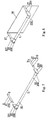
- a LED is used, being featured inclusively with a small volume, a low weight, a fast reaction, a long service life, a low attenuation, a strong exterior, an anti-vibration, an easy direction design, a low voltage, a low current, a low conversion loss, a low heat radiation, an easy yield, and an environmental protection on a long thin lamp rack unit 1.
- Several white-light LEDs 11 are arranged on a circuit and distributed side by side. Said LEDs 11 are arranged in parallel and independent, and their pedestal are adhered with glue or fixed with a plug dowel. Two terminals of the lamp rack unit 1 are changed in different manners of fixing and located by using several securing seats 2 and connection seats 3.
- a small billboard W or a notice board being projected for illumination may be provided at one end of the lamp rack unit 1 and several latches 13 for the holes are provided at the other terminal.
- the securing seat 2 may be a flank fixing rack 21 of which one terminal is fixed with screws to two flanks at a rear of the small billboard W and the other terminal is formed with an annular hole 211 corresponding to the hole of said latch 13 for clamping at an angle required.
- the white-light LEDs 11 are separately distributed in parallel, so that the light source given from the projecting lamp being evenly scattered on the billboard W for evenly distributed rays of light.
- the white-light LEDs 11 are connected in parallel, and in case that a single lamp is damaged, the rests of lamps are not affected and keep working; thus, only the damaged white-light LED 11 could be replaced, thereby the performance of said projecting lamp unit being increased and low cost of repair being achieved.
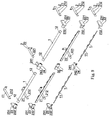
- Several locating holes 12 may be formed at two terminals of the lamp rack unit 1, and several wedge holes 212 are alternatively formed at the other terminal of the flank fixing rack 21 and wedged in a revolving mount 231 of the revolving padlock 23.
- the revolving padlock 23 is formed in the structure of said securing seat 2 to adjust a revolving plate 232 of the revolving padlock 23 for a required angle of illumination, and thus the locating holes 12 at the two terminals of the lamp rack unit 1 are respectively wedged into the revolving plate 232 with the revolving padlock 23 for location in another manner.
- Said several locating holes 12 may be formed at the two terminals of the lamp rack unit 1, and several locating holes 213 are alternatively formed at the other terminal of the flank fixing rack 21 and locked with a screw 214 to a terminal of a two-way rack 25.
- Said two-way rack 25 is formed in the structure of said securing seat 2 at the required angle of illumination, and thus the locating holes 12 at the two terminals of said lamp rack unit 1 are spirally locked to the other terminal of each of the 2 two-way racks 25 respectively, which is another manner for assembly.
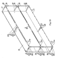
- the securing seat 2 may be in the form of several flank fixing racks 21.
- a top-and-bottom fixing rack 22 is spirally locked to a rear side of the large billboard W and the other terminal is formed with the annular hole 211 corresponding to the hole of said latch 13.
- several fixing holes 221 and several lamp rack units 1 are provided and locked at the angle of illumination onto the flank fixing rack 21 and the top-and-bottom fixing rack 22.
- a middle connection seat 3 may be a middle piece rack 31 provided with several connection holes 311 locked to the opposite terminals of said two lamp rack units 1.
- Several wedge holes 212 are alternatively formed at the other terminal of the flank fixing rack 21, and the flank fixing rack 21 and the top-and-bottom fixing rack 22 are respectively wedged into the revolving mount 231 of said revolving padlock 23 and a buckle mount 241 of the three-way padlock 24.
- the revolving padlock 23 and the three-way padlock 24 are formed in the structure of said securing seat 2 to adjust a revolving plate 232 and a buckle plate 242 for the required angle of illumination.
- the lamp rack unit 1 wedges the locating holes 12 at the two terminals into said revolving plate 232 and the buckle plate 242.
- the middle connection seats 3 may be the two-way padlocks 32 that may be wedged to the opposite terminals of the two lamp rack unit 1.
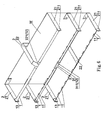
- Several locating holes 213 are alternatively formed at the other terminal of the flank fixing rack 21, and the flank fixing rack 21 and the top-and-bottom fixing rack 22 are respectively locked with screws 214 to lock holes 262 in a rack 261 of a three-way rack 26, lock holes on a base 271 of a T rack 27, lock holes 282 on a base 281 of a four-way rack 28, and lock holes 291 in an upright rack 29.
- the three-way rack 26, the T rack 27, the four-way rack 28, and the upright rack 29 are formed in the structure of securing seat 2, and the three-way rack 26, the T rack 27, and the four-way rack 28 are formed at the required angle of illumination. So the locating holes 12 at the two terminals of the lamp rack unit 1 are respectively spirally locked onto the lock holes 262 at one terminal of each three-way rack 26, the lock holes 272 at the two opposite terminals of the T rack 27, and the lock holes 282 at an inner terminal of the four-way rack 28.
- the upright rack 29 is spirally fixed between the three-way rack 26 and the four-way rack 28 to enhance the strength and durability of the structure
- the middle connection seat 3 may be a link mount 33 provided with several fixing holes that may be spirally fixed to the opposite terminals of said two lamp rack units 1 so that the white-light LED projecting lamp unit may be flexibly arranged in an area to be projected in the requirements of equal area and equal illumination for more power saving, more even light, and longer service life, thereby a wide illumination being achieved.
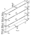
- a plurality of layers of illumination racks may be assembled with the securing seat 2 and the connection seat 3.
- the white-light LED lamps 11 are distributed in parallel on several long thin lamp rack units 1; the lamp rack unit 1 of which having a volume that occupies a small area, so that the surface of said billboard W is easily recognized from a distance, thereby a degree of recognition of the board surface being not affected and the ray of light given by the projecting lamp being even.
- the white-light LED lamp 11 featured with a low voltage, a low current, and a low conversion loss may be matched with a solar power panel or a small windmill as a power accumulator for achievement of self-power-saving, thereby no extra power supply being required.
- the white-light LED lamps 11 are distributed in parallel on the lamp rack unit 1, because of the fact that they are featured with the low weight, small volume, and even light scattering. Further, they are assembled with different securing seats 2 and connection seats 3 for a practical benefit of external light source projecting.
Landscapes
- Physics & Mathematics (AREA)
- General Physics & Mathematics (AREA)
- Engineering & Computer Science (AREA)
- Theoretical Computer Science (AREA)
- Illuminated Signs And Luminous Advertising (AREA)
Priority Applications (1)
| Application Number | Priority Date | Filing Date | Title |
|---|---|---|---|
| EP08000254A EP2079110A1 (fr) | 2008-01-09 | 2008-01-09 | Structure d'illumination de DEL |
Applications Claiming Priority (1)
| Application Number | Priority Date | Filing Date | Title |
|---|---|---|---|
| EP08000254A EP2079110A1 (fr) | 2008-01-09 | 2008-01-09 | Structure d'illumination de DEL |
Publications (1)
| Publication Number | Publication Date |
|---|---|
| EP2079110A1 true EP2079110A1 (fr) | 2009-07-15 |
Family
ID=39456384
Family Applications (1)
| Application Number | Title | Priority Date | Filing Date |
|---|---|---|---|
| EP08000254A Ceased EP2079110A1 (fr) | 2008-01-09 | 2008-01-09 | Structure d'illumination de DEL |
Country Status (1)
| Country | Link |
|---|---|
| EP (1) | EP2079110A1 (fr) |
Citations (5)
| Publication number | Priority date | Publication date | Assignee | Title |
|---|---|---|---|---|
| US6510633B1 (en) * | 2000-06-23 | 2003-01-28 | William C. Bledsoe | Panel illustration apparatus |
| US20030099105A1 (en) * | 2001-11-27 | 2003-05-29 | Watson Marion H. | Lighting apparatus for a sign |
| US20060164833A1 (en) * | 2005-01-26 | 2006-07-27 | Pelka & Associates | Cylindrical irradiance-mapping lens and its applications to LED shelf-lighting |
| US7181876B1 (en) * | 2002-02-20 | 2007-02-27 | Ahmadi William Y | LED sign visibility enhancing device |
| FR2899008A1 (fr) * | 2006-03-27 | 2007-09-28 | Jcdecaux Sa | Dispositif d'affichage a ecran a cristaux liquides. |
-
2008
- 2008-01-09 EP EP08000254A patent/EP2079110A1/fr not_active Ceased
Patent Citations (5)
| Publication number | Priority date | Publication date | Assignee | Title |
|---|---|---|---|---|
| US6510633B1 (en) * | 2000-06-23 | 2003-01-28 | William C. Bledsoe | Panel illustration apparatus |
| US20030099105A1 (en) * | 2001-11-27 | 2003-05-29 | Watson Marion H. | Lighting apparatus for a sign |
| US7181876B1 (en) * | 2002-02-20 | 2007-02-27 | Ahmadi William Y | LED sign visibility enhancing device |
| US20060164833A1 (en) * | 2005-01-26 | 2006-07-27 | Pelka & Associates | Cylindrical irradiance-mapping lens and its applications to LED shelf-lighting |
| FR2899008A1 (fr) * | 2006-03-27 | 2007-09-28 | Jcdecaux Sa | Dispositif d'affichage a ecran a cristaux liquides. |
Similar Documents
| Publication | Publication Date | Title |
|---|---|---|
| US8083373B2 (en) | LED retrofit for fluorescent backlit signs | |
| US10890311B2 (en) | Retrofit LED lighting system for replacement of fluorescent lamp | |
| US7488097B2 (en) | LED lamp module | |
| US9068719B2 (en) | Light engines for lighting devices | |
| US7357528B2 (en) | CCFL illuminated device and method of use | |
| EP2480824B1 (fr) | Moteur lumière pour dispositifs d'éclairage | |
| US7645052B2 (en) | LED ceiling tile combination, LED fixture and ceiling tile | |
| US8227813B2 (en) | LED light source utilizing magnetic attachment | |
| US8262249B2 (en) | Linear solid-state lighting with broad viewing angle | |
| CN100591979C (zh) | 一种led照明灯 | |
| US8727566B1 (en) | Assembly and method for retrofitting LED lights into a fluorescent bulb ceiling fixture | |
| MX2012011048A (es) | Modulo de iluminacion de led y lampara de iluminacion utilizando el mismo. | |
| US9488351B1 (en) | System and method for replacing fluorescent bulbs with LED lights in a ceiling fixture with a metal troffer | |
| US20100135006A1 (en) | LED light group lamp | |
| CN101761839B (zh) | 易于拆装的led照明装置 | |
| KR200483092Y1 (ko) | 확장이 용이한 엘이디 실내 조명장치 | |
| EP2079110A1 (fr) | Structure d'illumination de DEL | |
| US10151467B2 (en) | Interconnection mechanism for LED bar lighting | |
| WO2014146438A1 (fr) | Tube de del à grand angle de faisceau de 120 degrés à 360 degrés | |
| CN202215993U (zh) | 提高多方向发光光效的led灯具 | |
| CN202220983U (zh) | 一种带有中心放射型发光体的led光源灯泡 | |
| CN220489036U (zh) | Led灯 | |
| KR101840393B1 (ko) | 고반사율, 고열전도율의 판재를 이용한 엘이디 등 기구 | |
| CN201652014U (zh) | 一种分体式路灯 | |
| CN209744100U (zh) | 一种反射式led灯泡 |
Legal Events
| Date | Code | Title | Description |
|---|---|---|---|
| PUAI | Public reference made under article 153(3) epc to a published international application that has entered the european phase |
Free format text: ORIGINAL CODE: 0009012 |
|
| 17P | Request for examination filed |
Effective date: 20080125 |
|
| AK | Designated contracting states |
Kind code of ref document: A1 Designated state(s): AT BE BG CH CY CZ DE DK EE ES FI FR GB GR HR HU IE IS IT LI LT LU LV MC MT NL NO PL PT RO SE SI SK TR |
|
| AX | Request for extension of the european patent |
Extension state: AL BA MK RS |
|
| AKX | Designation fees paid | ||
| RBV | Designated contracting states (corrected) |
Designated state(s): AT BE BG CH CY LI |
|
| REG | Reference to a national code |
Ref country code: DE Ref legal event code: 8566 |
|
| STAA | Information on the status of an ep patent application or granted ep patent |
Free format text: STATUS: THE APPLICATION HAS BEEN REFUSED |
|
| 18R | Application refused |
Effective date: 20110318 |