EP2079080B1 - Vorrichtung und Verfahren zur Tonsynthese - Google Patents
Vorrichtung und Verfahren zur Tonsynthese Download PDFInfo
- Publication number
- EP2079080B1 EP2079080B1 EP09000251.0A EP09000251A EP2079080B1 EP 2079080 B1 EP2079080 B1 EP 2079080B1 EP 09000251 A EP09000251 A EP 09000251A EP 2079080 B1 EP2079080 B1 EP 2079080B1
- Authority
- EP
- European Patent Office
- Prior art keywords
- reed
- lip
- displacement
- arithmetic operation
- motion equation
- Prior art date
- Legal status (The legal status is an assumption and is not a legal conclusion. Google has not performed a legal analysis and makes no representation as to the accuracy of the status listed.)
- Not-in-force
Links
- 238000000034 method Methods 0.000 title claims description 32
- 230000015572 biosynthetic process Effects 0.000 title claims description 25
- 238000003786 synthesis reaction Methods 0.000 title claims description 25
- 235000014676 Phragmites communis Nutrition 0.000 claims description 371
- 238000006073 displacement reaction Methods 0.000 claims description 114
- 238000003825 pressing Methods 0.000 claims description 77
- 238000004364 calculation method Methods 0.000 claims description 12
- 238000005452 bending Methods 0.000 claims description 11
- 230000002194 synthesizing effect Effects 0.000 claims description 10
- 230000004044 response Effects 0.000 claims description 8
- 238000006243 chemical reaction Methods 0.000 description 46
- 238000010586 diagram Methods 0.000 description 23
- 241001125929 Trisopterus luscus Species 0.000 description 21
- 230000000704 physical effect Effects 0.000 description 19
- 238000012545 processing Methods 0.000 description 17
- 238000010276 construction Methods 0.000 description 16
- 230000014509 gene expression Effects 0.000 description 15
- 238000012360 testing method Methods 0.000 description 13
- 230000008859 change Effects 0.000 description 11
- 230000008569 process Effects 0.000 description 10
- 230000005540 biological transmission Effects 0.000 description 8
- 101150024570 Mlip gene Proteins 0.000 description 7
- 230000004048 modification Effects 0.000 description 6
- 238000012986 modification Methods 0.000 description 6
- 230000003111 delayed effect Effects 0.000 description 4
- 230000008030 elimination Effects 0.000 description 4
- 238000003379 elimination reaction Methods 0.000 description 4
- 238000005259 measurement Methods 0.000 description 4
- 238000004088 simulation Methods 0.000 description 4
- 244000273256 Phragmites communis Species 0.000 description 3
- 230000009471 action Effects 0.000 description 3
- 230000008901 benefit Effects 0.000 description 3
- 238000007664 blowing Methods 0.000 description 2
- 230000001934 delay Effects 0.000 description 2
- 239000000463 material Substances 0.000 description 2
- 239000000203 mixture Substances 0.000 description 2
- 230000005855 radiation Effects 0.000 description 2
- 230000009466 transformation Effects 0.000 description 2
- 238000002940 Newton-Raphson method Methods 0.000 description 1
- 238000005263 ab initio calculation Methods 0.000 description 1
- 230000001133 acceleration Effects 0.000 description 1
- 238000004891 communication Methods 0.000 description 1
- 230000007423 decrease Effects 0.000 description 1
- 238000009792 diffusion process Methods 0.000 description 1
- 238000002474 experimental method Methods 0.000 description 1
- 238000001914 filtration Methods 0.000 description 1
- 238000009472 formulation Methods 0.000 description 1
- 230000010354 integration Effects 0.000 description 1
- 230000003993 interaction Effects 0.000 description 1
- 239000011159 matrix material Substances 0.000 description 1
- 230000010355 oscillation Effects 0.000 description 1
- 239000004065 semiconductor Substances 0.000 description 1
- 238000006467 substitution reaction Methods 0.000 description 1
- 230000002123 temporal effect Effects 0.000 description 1
Images




Classifications
-
- G—PHYSICS
- G10—MUSICAL INSTRUMENTS; ACOUSTICS
- G10H—ELECTROPHONIC MUSICAL INSTRUMENTS; INSTRUMENTS IN WHICH THE TONES ARE GENERATED BY ELECTROMECHANICAL MEANS OR ELECTRONIC GENERATORS, OR IN WHICH THE TONES ARE SYNTHESISED FROM A DATA STORE
- G10H5/00—Instruments in which the tones are generated by means of electronic generators
- G10H5/007—Real-time simulation of G10B, G10C, G10D-type instruments using recursive or non-linear techniques, e.g. waveguide networks, recursive algorithms
-
- G—PHYSICS
- G10—MUSICAL INSTRUMENTS; ACOUSTICS
- G10H—ELECTROPHONIC MUSICAL INSTRUMENTS; INSTRUMENTS IN WHICH THE TONES ARE GENERATED BY ELECTROMECHANICAL MEANS OR ELECTRONIC GENERATORS, OR IN WHICH THE TONES ARE SYNTHESISED FROM A DATA STORE
- G10H2250/00—Aspects of algorithms or signal processing methods without intrinsic musical character, yet specifically adapted for or used in electrophonic musical processing
- G10H2250/471—General musical sound synthesis principles, i.e. sound category-independent synthesis methods
- G10H2250/511—Physical modelling or real-time simulation of the acoustomechanical behaviour of acoustic musical instruments using, e.g. waveguides or looped delay lines
- G10H2250/521—Closed loop models therefor, e.g. with filter and delay line
Definitions
- the present invention relates to a technique for synthesizing tones of wind instruments that generate tones in response to vibration of a reed.
- tone synthesis apparatus of a physical model type (i.e., physical model tone generators) for synthesizing tones by simulating the tone generating principles of musical instruments.
- tone synthesis apparatus are techniques disclosed in: R.T. Schumacher "Ab Initio Calculations of the Oscillations of a Clarinet", ACUSTICA, 1981, Volume 48 No. 2, p.75 - p.85 (hereinafter referred to as Non-patent Literature 1); and S.D. Sommerfeldt, W.J.
- Non-patent Literature 1 discloses a technique for simulating behavior of a clarinet by modeling a reed as a rigid air valve freely movable in its entirety
- Non-patent Literature 2 discloses a technique for simulating behavior of a clarinet by modeling a reed using a vibrating member in the form of an elongate plate fixed at one end (i.e., cantilevered vibrating beam).
- Non-patent Literatures 1 and 2 only simulate simple external actions on the reed.
- behavior of the reed of an actual wind instrument can not be reproduced faithfully, so that it has been difficult to synthesize tones sufficiently approximate to tones of an actual wind instrument.
- Federico Avanzini "Chapter 3 Single reed models", COMPUTATIONAL ISSUES IN PHYSICALLY-BASED SOUND MODELS (PhD); 2001, XP055152524, Universita degli Studi di Padova; http://www.dei.unipd.it/ ⁇ avanzini/phdthesis/downloads/ch3.pdf discusses single reed modeling and was used as a basis for the preamble of the independent claims. A lumped model is reviewed, and an efficient and accurate discretization scheme is developed. The limitations of existing lumped models are discussed, and an improved non-linear model is formulated. In this new formulation, the interaction of the reed with the mouthpiece and the player's embouchure are taken into account, although at the expense of a slight increase of the model complexity.
- the present invention provides an improved apparatus for synthesizing a tone of a wind instrument that is generated in response to vibration of a reed contacting a lip during blowing or performance of the wind instrument, as set forth in claim 1.
- the present invention can accurately simulate behavior of the reed as compared to the conventional construction where behavior of the reed is calculated on the basis of a motion equation that does not reflect therein. As a result, the present invention can faithfully reproduce tones of an actual wind instrument.
- each time intensity of the external force acting on the lip changes the first arithmetic operation section calculates displacement of the lip corresponding to the changed intensity of the external force acting on the basis of the first motion equation and the second motion equation, and the second arithmetic operation section calculates displacement of the reed by substituting the displacement of the lip, calculated by the first arithmetic operation section, into the motion equation of coupled vibration. Because such an arrangement allows any change of the external force acting on the lip to be reflected in the displacement of the reed, the present invention can synthesize a variety of tones corresponding to a performance or rendition style that varies pressing force on the lip.
- the first motion equation and the second motion equation include a spring constant of the lip that changes in accordance with a position in the lip and intensity of pressing force acting on the lip.
- Such an arrangement can faithfully simulate the characteristic of an actual lip that a spring constant of the lip changes in accordance with the intensity of the pressing force and the position in the lip.
- the present invention can accurately synthesize tones of a wind instrument.
- the first motion equation includes bending rigidity that changes in accordance with a position of the reed.
- Such an arrangement can faithfully simulate the characteristic of an actual reed that bending rigidity of the reed (product between a second moment of area and a Young's modulus of the reed MR) changes in accordance with the position of the reed.
- the present invention can accurately synthesize tones of a wind instrument as compared to the conventional construction where the reed is simulated with a mere elongated plate-shaped vibrating member that does not change in sectional shape.
- the second arithmetic operation section limits the displacement of the reed to within a predetermined range. Because the displacement of the reed calculated on the basis of the motion equation of coupled vibration is limited to within the predetermined range, it is possible to prevent simulation of a situation where the reed is displaced to outside a displacement range of an actual reed, so that tones of an actual wind instrument can be reproduced accurately.
- the range within which the displacement of the reed is limited is preferably set to a range from the bottom surface of the lip and a surface of the mouthpiece opposed to the bottom surface.
- the motion equation of coupled vibration includes at least one of internal resistance of the lip that changes in accordance with a position in the lip and internal resistance of the reed that changes in accordance with a position in the reed.
- Such an arrangement can simulate a situation where the internal resistance of the lip and internal resistance of the reed change in accordance with the positions, and thus, the present invention can faithfully reproduce tones of an actual wind instrument as compared to the conventional construction where the internal resistance of the lip and the internal resistance of the reed are set at fixed values.
- the motion equation of coupled vibration includes at least one of internal resistance of the lip that changes in accordance with a position in the lip and pressing force acting on the lip and internal resistance of the reed that changes in accordance with a position in the reed and pressing force acting on the reed.
- Such an arrangement can simulate a situation where the internal resistance of the lip and the internal resistance of the reed change in accordance with the intensity of the pressing force, and thus, the present invention can faithfully reproduce tones of an actual wind instrument as compared to the conventional construction where the internal resistance of the lip and the internal resistance of the reed are set at fixed values.
- the tone synthesis apparatus of the present invention can be implemented not only by hardware electronic circuitry, such as DSPs (Digital Signal Processors) dedicated to individual processes, but also by a cooperation between a general-purpose arithmetic operation processing apparatus and a program.
- the program of the present invention is a program for synthesizing a tone of a wind instrument that is generated in response to vibration of a reed contacting a lip during blowing or performance of the wind instrument, which causes a computer to perform: a first arithmetic operation step of solving a first motion equation representative of behavior of the reed in an equilibrium state with external force acting on the lip and a motion equation representative of behavior of the lip in the equilibrium state, to thereby calculate displacement of the lip and displacement of the reed in the equilibrium state; a second arithmetic operation step of solving a motion equation of coupled vibration of the lip and the reed with calculation results of the first arithmetic operation step used as initial values of the displacement of the lip and the displacement of the
- the program of the present invention is provided to a user in a computer-readable storage medium and then installed into a computer, or delivered to a user via a communication network and then installed into a computer.
- Fig. 1 is a block diagram showing an example setup of a first embodiment of a tone synthesis apparatus of the present invention.
- This tone synthesis apparatus 100 is constructed to synthesize tones by simulating, through arithmetic operations, the tone generating principles of a single-reed wind instrument, such as a saxophone or clarinet.
- the tone synthesis apparatus 100 is implemented by a computer system that comprises an arithmetic operation processing device 10, a storage device 42 and a sounding device 46.
- the arithmetic operation processing device such as a CPU (Central Processing Unit) 10, executes programs, stored in the storage device 42, to generate and output tone data representative of a time-varying waveform of a wind instrument (i.e., temporal variation of sound pressure).
- the storage device 42 stores therein programs for execution by the arithmetic operation processing device 10 and data for use by the arithmetic operation processing device 10.
- Magnetic storage device, semiconductor storage device or other conventionally-known storage device may be employed as the storage device 42.
- the input device 44 includes a plurality of operating members operable by a user or human player. Via the input device 44, the human player can input, to the arithmetic operation processing device 10, various parameters to be used for tone synthesis. Input equipment, such as a keyboard and mouse, and musical-instrument type input equipment, such as MIDI (Musical Instrument Digital Interface) controller, for inputting information pertaining to a performance of a wind instrument is employable as the input device 44.
- MIDI Musical Instrument Digital Interface
- the sounding device 46 radiates a sound wave corresponding to tone data output by the arithmetic operation processing device 10.
- the tone synthesis apparatus in practice further includes a D/A converter for converting tone data into an analog tone signal, and an amplifier for amplifying and outputting such a tone signal.
- the arithmetic operation processing device 10 functions also as a setting section 12 and a synthesis section 14.
- various functions of the arithmetic operation processing device 10 may be implemented distributively by a plurality of integrated circuits. Further, part of the functions of the processing device 10 may be implemented by dedicated circuitry (DSP) for tone synthesis.
- DSP dedicated circuitry
- the setting section 12 sets parameters necessary for tone synthesis.
- the synthesis section 14 generates tone data on the basis of the parameters set by the setting section 12, and it includes a reed simulating section 31, a tubular body simulating section 33 and a transmission simulating section 35.
- the reed simulating section 31 simulates coupled vibration of the player's lip and the reed.
- the tubular body simulating section 33 simulates behavior of a tubular portion of the wind instrument from the mouthpiece to the bell (namely, tubular body portion other than the reed).
- the transmission simulating section 35 simulates impartment of transmission characteristics to radiated sounds from the bell and individual tone holes.
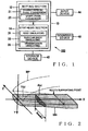
- Fig. 2 is a conceptual diagram showing the reed and neighborhood thereof of the wind instrument which are to be simulated by the reed simulating section 31.
- the reed MR is a vibrating member of an elongated plate shape having one end fixed to the mouthpiece MP. Let it be assumed here that X, Y and Z axes intersect with one another at an original point coinciding with a middle point, in a width direction, of a distal end of the reed MR. The Z axis extends in a width direction of the reed MR.
- the X axis intersects with the Z axis in the upper surface (i.e., surface opposed to the mouthpiece MP) of the reed MR when no external force is acting on the reed MR. Further, the Y axis extends in a vertical (thickness) direction of the reed MR to intersect with the X and Z axes.
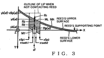
- Fig. 3 is a schematic exaggerated view of the reed MR and neighborhood thereof, which are to be simulated by the reed simulating section 31, taken in the Z direction, which is explanatory of how a human player's lip ML contacts the reed MR at the time of a performance of the wind instrument.
- the reed simulating section 31 simulates a state where the human player presses the lip ML against the reed MR with teeth MT during the performance of the wind instrument.
- the lip ML contacts a portion of the reed MR from a position xlip1 (adjacent to the distal end of the reed MR) to a position xlip2 (adjacent to the base of the reed MR) in the X direction. Further, the teeth MT of the human player contact a portion of the lip ML from a position xteeth1 (adjacent to the distal end of the reed MR) to a position xteeth2 (adjacent to the base of the reed MR) in the X direction, to thereby cause pressing force flip(x) to act uniformly on the reed MR.
- Fig. 4 is a block diagram showing functions of the reed simulating section 31. In a left area of Fig. 4 are shown parameters set by the setting section 12 and then stored in the storage device 42. The following lines describe meanings of the parameters.
- Stiff(x) represents bending rigidity (N ⁇ m 2 ) of the reed MR at a position x in the X direction.
- the bending rigidity Stiff(x) corresponds to a product between a Young's modulus of the reed MR and a second moment of area I(x) [m 4 ] of the reed MR at the position x. As shown in Fig.
- Breed(x) represents a horizontal width [m] (i.e., dimension in the Z direction) at the position x
- A(x) is a sectional area (i.e., area in a Y-Z plane passing the position x) [m 2 ] of the reed MR at the position x.
- the sectional shape of the reed MR varies depending on where the position x in the X direction is.
- the second moment of area I(x), horizontal width Breed(x) and sectional area A(x) of the reed MR to be used in calculation of the bending rigidity Stiff(x) are functions of the position x.
- ⁇ reed(x) represents a distribution of internal resistance [(kg/sec)/m] of the reed MR
- ⁇ reed(x) represents a density [kg/m 3 ] of the reed MR.
- klip(x) represents a distribution of spring constant [N/m 2 ], in the X direction, of the lip ML (e.g., spring constant for a unit length, in the X direction, of the lip ML).
- dlip(x) represents a dimension in the Y direction (i.e., thickness) [m] of the lip ML at the position x when no external force acts on the lip ML.
- ⁇ lip(x) represents a distribution of internal resistance [kg/sec)/m] of the lip ML at the position x.
- mlip(x) represents a distribution of mass [kg/m], in the X direction, of the lip ML.
- the distribution of spring constant klip(x), thickness dlip(x), distribution of internal resistance ⁇ lip(x) and distribution of mass mlip(x) vary depending on where the position x in the X direction is.
- H(x) represents a position, in the Y direction, on the surface of the mouthpiece MP opposed to the reed MR, as seen in Fig. 2 ; such a position H(x) will hereinafter be referred to as "facing position".
- the facing position H(x) corresponds to a limit value (i.e., lower limit value) of the displacement of the reed MR.
- Zc represents characteristic impedance to an air flow at a starting point of a portion of the mouthpiece MP that can be regarded as a tubular body (i.e., the base of the reed MR).
- the reed simulating section 31 comprises first, second, third and fourth arithmetic operation sections 311, 312, 313 and 314.
- the first arithmetic operation section 311 calculates displacement yo(xf) of the reed MR and displacement yb(xf) of the bottom surface of the lip ML when the lip ML is in an equilibrium state with pressing force flip(xf) caused to statically act on a position xf, in the Y direction, of the lip ML.
- the third and fourth arithmetic operation sections 313 and 314 calculate pressure POUT of a sound wave to be output from the reed MR to the tubular body portion (adjacent to the mouthpiece MP) on the basis of the displacement y(x,t) of the reed MR. Details of processing performed by the reed simulating section 31 will be discussed below.
- FIG. 3 shows in a schematically simplified manner the upper surface of the lip ML as positioned on the upper surface of the reed MR.
- R 1 ⁇ 2 ⁇ x 2 Stiff x f ⁇ ⁇ 2 d 1 ⁇ x 2
- R 2 k lip x f ⁇ d 2
- Motion Equations A1 and A2 can be derived.
- the first arithmetic operation section 311 shown in Fig. 4 calculates displacement yb(xf) of the bottom surface of the lip ML and displacement y0(xf) of the reed MR by solving Motion Equations A1 and A2 by substituting thereinto the bending rigidity Stiff(xf), pressing force flip(xf), spring constant klip(xf) and thickness dlip(xf). More specifically, the first arithmetic operation section 311 calculates displacement y0(xf) of the reed MR from Motion Equation A1 using difference equation conversion, Gaussian elimination method or the like and then calculates displacement yb(xf) of the lip ML by substituting the calculated displacement y0(xf) into Motion Equation A2. How to solve Motion Equation A1 will be described later.
- Dynamic characteristics when the lip ML and reed MR vibrate in a coupled manner can be expressed by Motion Equation B below.
- m lip x + ⁇ reed A x ⁇ 2 y x t ⁇ t 2 + ⁇ 2 ⁇ x 2 Stiff x ⁇ ⁇ 2 y x t ⁇ x 2 + ⁇ lip x + ⁇ reed x ⁇ y x t ⁇ t k lip x y b x ⁇ d lip x ⁇ y x t + p t ⁇ P + b reed x
- the second arithmetic operation section 312 calculates displacement y(x, t) of the reed MR by setting the displacement y0(xf), calculated by the first arithmetic operation section 311, as an initial value of the displacement y(xt) of the reed MR and substituting the displacement yb(xf), calculated by the first arithmetic operation section 311, into the displacement yb(x) of the lip ML in Motion Equation B.
- the right side of Equation B represents external force fex(x) acting on the position x, in the X direction, of the reed MR.
- the second arithmetic operation section 312 calculates external force fex(x) by not only substituting into the right side of Motion Equation B the parameters breed(x), P, klip(x) and dlip(x) set by the setting section 12 and pressure p(t) calculated by the fourth arithmetic operation section 314 but also substituting the displacement y0(xf) and displacement yb(xf), calculated by the first arithmetic operation section 311, into the right side of Motion Equation B as initial values of the displacement y(x, t) and displacement yb(x).
- the pressure p(t) is pressure in a portion of a gap between the reed MR and the mouthpiece MP close to the distal end of the reed MR (hereinafter referred to as "immediately-above-reed portion"). Calculation, by the fourth arithmetic operation section 314, of the pressure p(t) will be described later.
- the second arithmetic operation section 312 calculates displacement y(x, t) of the reed MR by substituting the parameters mlip(x), A(x), ⁇ reed(x), Stiff(x) and ⁇ reed, set by the setting section 12, into the left side of Motion Equation B and setting the external force fex(x) calculated earlier into the right side of Motion Equation B. How to solve Motion Equation B will be described later.
- Motion Equation B can be transformed into Equation B1 below.
- m lip x + ⁇ reed A x ⁇ 2 y x t ⁇ t 2 + E reed ⁇ 2 ⁇ x 2 I x ⁇ ⁇ 2 y ⁇ x 2 + 2 ⁇ ⁇ x I x ⁇ ⁇ 3 y ⁇ x 3 + I x ⁇ ⁇ 4 y ⁇ x 4 + ⁇ lip x + ⁇ reed x ⁇ y x t ⁇ t k lip x y b x ⁇ d lip x ⁇ y x t + p t ⁇ P ⁇ b reed x
- the position x in the X direction is discretized in such a manner that the discretized positions are distributed at equal intervals ⁇ x.
- Equation B2 Mathematical Expression B1 above can be rewritten as Equation B2 below.
- Equation B2 m lip x + ⁇ reed A x y n , i + 1 ⁇ 2 y n i + y n , i ⁇ 1 ⁇ t 2 + E reed I ⁇ ⁇ y n + 1 , i ⁇ 2 y n i + y n ⁇ 1 , i ⁇ x 2 + E reed 2 I ⁇ ⁇ y n + 2 , i ⁇ 3 y n + 1 , i + 3 y n i ⁇ y n ⁇ 1 , i ⁇ x 3 + E reed I ⁇ y n + 2 , i ⁇ 4 y n + 1 , i + 6 y n i ⁇ 4 y n ⁇ 1 , i + y n ⁇ 2 , i
- Equation B3 approximately expressing Equation B2 above is derived by adding together (1) an equation obtained by multiplying the second term through to the fourth term in the left side of Equation B2 by 1/2 and (2) an equation obtained by substituting "i" in Equation B2 by (i + 1) and then multiplying the second term through to the fourth term in the left side of Equation B2 by 1/2.
- Equation B4_3 is derived by adding together Equation B4_1 and Equation B4_2, and the following Equation B4_4 is derived by subtracting Equation B4_2 from three times of Equation B4_3.
- Equation B4_3 is derived by adding together Equation B4_1 and Equation B4_2, and the following Equation B4_4 is derived by subtracting Equation B4_2 from three times of Equation B4_3.
- Equation B4_5 is derived by substituting 2 into n in Equation B4 above.
- a 1 2 y 0 , i + 1 + a 2 2 y 1 , i + 1 + a 3 2 y 2 , i + 1 + a 4 2 y 3 , i + 1 + a 5 n y 4 , i + 1 ⁇ a 1 2 y 0 i + a 2 2 y 1 i ⁇ b 3 2 y 2 i + a 4 2 y 3 i + a 5 2 , y 4 i + c 1 2 y 2 , i ⁇ 1 + k lip n y b n ⁇ d lip n + p i ⁇ P b reed n
- the Gaussian elimination method is suitable as a solution method for Equation B5 above. Because two rows and two columns in a left upper portion of Equation B5 above constitute a diagonal matrix by Equation B4_3 and Equation B4_4 being derived from Equation B4_1 and Equation B4_2, there can be achieved the benefit that the necessary quantity of arithmetic operations to be performed in the Gaussian elimination method can be reduced.
- the second arithmetic operation section 312 calculates displacement y(x, t) of the reed MR by solving Equation B5 using the displacement (y0(xf), yb(xf)), calculated by the first arithmetic operation section 311, as initial values of the displacement y(x, y) and yb(x).
- the second arithmetic operation section 312 first calculates variables y(0, i+1) to y(N-1, i+1), representing future displacement, in the left side of Equation B5, by not only substituting variables y0(0) - y0(N-1) and y0(2) to y0(N-1), calculated by the first arithmetic operation section 311, into both of the variables y0(0, i) to y0(N-1, i), representing current displacement, in the right side of Equation B5 and variables y(2, i-1) to y(N-1, i-1), representing previous displacement, in the right side of Equation B5 but also substituting the displacement yb(xf), calculated by the first arithmetic operation section 311, into yb(2) to yb(N-1) of Equation B5.
- the second arithmetic operation section 312 calculates variables y(0, i+1) to y(N-1, i+1), representing future displacement in the left side of Equation B5, by solving Equation B5 by not only substituting variables y(2, i) to y(N-1, i), representing current displacement, into variables y(2, 1-1) to y(N-1, i-1), representing previous displacement, in the right side of Equation B5, but also substituting variables y(0, i+1) to y(N-1, i+1), representing last-calculated future displacement, into variables y(0, i) to y(N-1, i), representing current displacement, in the right side of Equation B5.
- the second arithmetic operation section 312 calculates a change over time of the displacement y(x, t) at each position x of the reed MR.
- the first arithmetic operation section 311 calculates new yo(xf) and yb(xf) by substituting the changed pressing force flip(x) into the pressing force flip(xf) in Motion Equations A1 and A2.
- the second arithmetic operation section 312 updates the numerical value to be substituted into yb(2) to yb(N-1) with the new displacement yb(xf).
- the second arithmetic operation section 312 does not reflect the calculated new displacement yo(xf) for the displacement y(0, i) to y(N-1, i) of Equation 5.
- the second arithmetic operation section 312 includes a range limiting section 32 that limits the displacement y(x, t) of the reed MR to within a predetermined range.
- the range limiting section 32 limits the displacement y(xt) of the reed MR, calculated from Equation B5, to a range from the displacement yb(xf) of the lip ML (i.e., position of the bottom surface of the lip ML which the teeth MT contacts), calculated by the first arithmetic operation section 311, to the facing position H(x) set by the setting section 12.
- the range limiting section 32 changes the displacement y(x, t) to the displacement yb(xf), but when the displacement y(x, t) of the reed MR exceeds (falls below) the facing position H(x), the range limiting section 32 changes the displacement y(x, t) to the facing position H(x).
- the displacement yb(x) of the bottom surface of the lip ML has been described above as the upper limit value of the displacement y(x, t) of the reed MR, but, because the lip ML has a thickness, a given position closer to the facing position H(x) than the displacement yb(x) by a predetermined value corresponding to the thickness of the lip ML (e.g., a fixed value corresponding to a minimum value of the thickness of the lip ML, or a variable value corresponding to a minimum value of the thickness of the lip ML and variable in accordance with the pressing force flip(x)).
- a predetermined value corresponding to the thickness of the lip ML e.g., a fixed value corresponding to a minimum value of the thickness of the lip ML, or a variable value corresponding to a minimum value of the thickness of the lip ML and variable in accordance with the pressing force flip(x)
- Motion Equation A1 is transformed into the following Difference Equation A1_A1 in a similar manner to the above-mentioned transformation from Motion Equation B1 to Equation B2.
- Equation A1_2 is transformed into the following Difference Equation A1_3 in a similar manner to the above-mentioned transformation from Equation B4 to Equation B5.
- the first arithmetic operation section 311 calculates displacement y0(x) (y(0) to y(N-1) in Equation A1_3) using the Gaussian elimination method or the like.
- the foregoing has been a specific example of the solution for Motion Equation A1.
- the third arithmetic operation section 313 of Fig. 4 calculates a volume flow rate f(t) in the immediately-above-reed portion on the basis of the parameters H(x), ⁇ air, breed(x) and Zc set by the setting section 12 and the displacement y(x, t) calculated by the second arithmetic operation section 312.
- the volume flow rate u(t) can be expressed by the following Equation C1, where "leff represents a distance from the distal end to the supporting point of the reed MR (i.e., effective length of the reed MR).
- u t ⁇ 0 l eff b reed x y • x t dx
- the third arithmetic operation section 313 calculates the volume flow rate u(t) by substituting into Equation C1 the width Breed(x) of the reed MR set by the setting section 12 and a time derivative of the displacement y(x, t) (i.e., velocity of the reed MR) calculated by the second arithmetic operation section 312 to perform numeric integration, such as the Simpson's method.
- the volume flow rate U(t) can be calculated in accordance with the following arithmetic operational sequence.
- the third arithmetic operation section 313 calculates a gap ⁇ (t) [m] between the mouthpiece MP and the reed MR at the distal end of the reed MR.
- the third arithmetic operation section 313 calculates effective mass M(t) [Kg] of air passing through the gap between the mouthpiece MP and the reed MR.
- the third arithmetic operation section 313 calculates effective mass M(t) by substituting into Equation C2 the horizontal width Breed(0) and air density ⁇ air of the reed MR, set by the setting section 12, and the relative ratio R(t).
- a 3 / 2 ⁇ ⁇ t 2 , where A represents a predetermined coefficient (e.g., A 0.0797). The following method is used in the calculation of the volume flow rate U(t) using Equation C3 above.
- Equation C3 can be transformed into the following Equation C4 using Equation D1 and Equation D2 to be described later:
- M t U • t P ⁇ 2 P in t ⁇ Z c U t ⁇ u t ⁇ U t 5 / 2
- Equation C5 the volume flow rate U(t) from Equation C5 using a numerical solution of nonlinear equations (e.g., Newton-Raphson method).
- the third arithmetic operation section 313 calculates, as a volume flow rate f(t), a difference between the volume flow rate U(t) and the volume flow rate (t) calculated in accordance with the above-described arithmetic operation sequence.
- the fourth arithmetic operation section 314 of Fig. 4 calculates output wave pressure POUT(t) and sound pressure p(t) of the immediately-above-reed portion p(t).
- the output wave pressure POUT(t) is pressure of a sound wave traveling forward from the reed MR through the interior of the tubular body portion (hereinafter referred to as "output wave").
- Portion of the sound wave traveling from the reed MR through the interior of the tubular body reflects off an open end (bell) of the wind instrument, and then that portion having traveled through the interior of the tubular body (hereinafter referred to as a "reflected wave”) travels backward through the interior of the tubular body to reach the interior of the mouthpiece MP.
- the output wave pressure POUT(t) corresponds to a sum of pressure produced by the volume flow rate f(t) and pressure PIN of the reflected wave traveling from the interior of the tubular body to the mouthpiece MP (this pressure will be referred to as "reflected wave pressure PIN").
- the reflected wave pressure PIN is calculated or arithmetically determined by the tubular body simulating section 33.
- the fourth arithmetic operation section 314 calculates the output wave pressure POUT(t) by substituting into Equation D1 above the characteristic impedance Zc set by the setting section 12, volume flow rate f(t) calculated by the third arithmetic operation section 313 and reflected wave pressure PIN calculated by the tubular body simulating section 33.
- the fourth arithmetic operation section 314 calculates the pressure P(t) by substituting into Equation D2 above the output wave pressure POUT(t) calculated on the basis of Equation D1 and reflected wave pressure PIN(t) calculated by the tubular body simulating section 33.
- the pressure P(t) calculated by the fourth arithmetic operation section 314 is fed back to the calculation (Equation B) of the external force fex(x) by the second arithmetic operation section 312 and calculation (Equation C) of the volume flow rate U(t) by the third arithmetic operation section 313.
- tubular body simulating section 33 As shown in Fig. 6 , a tubular body section (extending from the mouthpiece to the bell) of an actual wind instrument can be approximated by a structure comprising k (k is a natural number) tubular unit portions U (U[1] - U[k]) connected together in series. Diameters and overall lengths of the individual tubular unit portions (namely, shape of each of the tubular body portions) are variably set.
- the tubular body simulating section 33 realizes behavior of a sound wave inside the tubular body portion by use of a physical model (hereinafter referred to as "tubular body model”) simulating the structure of Fig. 6 .
- tubular body model a physical model
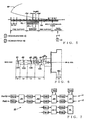
- Fig. 7 is a block diagram showing an example construction of the tubular body model used by the tubular body simulating section 33.
- the tubular body model includes: delay elements D A (D A [1] - D A [k]) provided on a path r1 in corresponding relation to the unit portions U; delay elements DB (DB[1] - DB[k]) provided on a path r2 in corresponding relation to the unit portions U, junctions or connecting sections J (J[1] - J[k-1]) provided between adjacent ones of the delay elements DA and between adjacent ones of delay elements D B ; hole portions TH (TH[1] - TH[k-1]) connected to some of the connecting sections J which are located at positions corresponding to tone holes of the wind instrument; and a bell section BL corresponding to the bell of the wind instrument.
- the path r1 simulates behavior of an output wave traveling through the interior of the tubular body portion from the mouthpiece MP to the bell (i.e., output wave pressure POUT(k, t)), while the path r2 simulates behavior of an output wave traveling through the interior of the tubular body portion from the bell to the mouthpiece MP (i.e., reflected wave pressure PIN(k, t)).
- Output wave pressure POUT(t) calculated by the reed simulating section 31 (fourth arithmetic operation section 314) is supplied, as an initial value POUT(1, t), to the delay element DA[1] of the first stage to be sequentially delayed by the delay elements DA[1]- DA[k] of the individual stages, and then reaches the bell section BL.
- the delay element DA[i] simulates a propagation delay of the output wave pressure POUT(i, t) in the i-th unit portion U[i].
- the bell section BL simulates radiation of a sound wave from the bell of the wind instrument and reflection of the sound wave at the distal end of the bell.
- the bell section BL includes a filter section 62 and a multiplication section 64.
- Output wave pressure POUT(k, t) output from the delay element DA[k] of the k-th stage (i.e., last stage) on the path r1 is supplied to the bell section BL.
- the filter section 62 includes a low-pass filter portion 621 and a subtraction portion 622.
- the low-pass filter portion 621 filters out components of a time waveform of the output wave pressure POUT(k, t), output from the k-th stage delay element DA[k], which exceed a cutoff frequency fCB.
- the subtraction portion 622 calculates radiated sound pressure PB(t) by subtracting the output of the low-pass filter portion 621 from the output wave pressure POUT(k, t) of the k-th stage delay element DA[k].
- the subtraction portion 622 functions as a high-pass filter that filters out components of the output wave pressure POUT(k, t) which fall below the cutoff frequency fCB.
- the radiated sound pressure PB(t) is equivalent to pressure of the sound wave radiated from the bell.
- the multiplication section 64 simulates reflection of a sound wave at a boundary between inner and outer sides of the bell of the wind instrument. Namely, the multiplication section 64 calculates reflected wave pressure PIN(k, t) by multiplying the output from the low-pass filter portion 621 by a coefficient rB and then outputs the calculated reflected wave pressure PIN(k, t) to the path r2 (more specifically, to the delay element DB[k] of Fig. 7 ). Because the sound wave reverses its phase and causes some loss at the time of the reflection, the coefficient rB is set at a negative number whose absolute value is, for example, smaller than one.
- the delay element DB[i] of Fig. 7 delays reflected wave pressure PIN(i, t), input from a preceding stage (closer to the bell section BL), by a predetermined delay amount dB[i].
- the delay element DB[i] simulates a propagation delay of the reflected wave pressure PIN(k, t) in the i-th unit portion U[i].
- the reflected wave pressure PIN(k, t) calculated by the bell section BL are sequentially delayed by the delay elements DB[k] - DB[1], and the reflected wave pressure PIN(1, t) output from the first-stage delay element DB[1] is used, as reflected wave pressure PIN(t), in arithmetic operations by the reed simulating section 31 (fourth arithmetic operation section 314).
- the connecting section (or junction) J simulates output wave diffusion and energy loss arising from inner diameter variation of the tubular body portion.
- the connecting section (or junction) J may be of either a two-port type as shown in (A) of Fig. 9 or a three-port type as shown in (B) of Fig. 9 .
- the two-port type connecting section J[i] includes: a multiplication section 71 for multiplying output wave pressure POUT(i, t), supplied via the path r1, by a coefficient ⁇ i; a multiplication section 72 for multiplying reflected wave pressure P IN (i+1, t), supplied via the path r2, by a coefficient ⁇ i ; an addition section 73 for adding together an output ( ⁇ i ⁇ POUT(i, t)) from the multiplication section 71 and an output ( ⁇ i ⁇ PIN(i+, t)) from the multiplication section 72; a subtraction section 74 for outputting a difference between the output from the addition section 73 and the output wave pressure POUT(i, t) to the path r2 as new reflected wave pressure PIN(i, t); and a subtraction section 75 for outputting a difference between the output from the addition section 73 and the reflected wave pressure PIN(i+1, t) to the path r1 as new output wave pressure POUT(i
- the three-port type connecting section J[i] shown in (B) of Fig. 9 is employed where a tone hole portion TH is connected, such as the connecting sections J[3] and J[4] shown in Fig. 7 .
- the three-port type connecting section J[i] includes, in addition to the aforementioned components of the two-port type connecting section J[i], a subtraction section 76 for outputting a difference between the output from the addition section 73 and sound pressure Ri(t) output from the i-th tone hole portion TH[i] to the tone hole portion TH[i] as sound pressure Qi(t), and a multiplication section 77 for multiplying the sound pressure Ri(t) by a coefficient ⁇ i.
- the tone hole portion TH[i] simulates radiation of a sound wave from an i-th tone hole and reflection of the sound wave at the tone hole.
- the tone hole portion TH[i] includes delay elements DE1 and DE2, a filter section 66 and a multiplication section 68, similarly to the bell section BL of Fig. 8 .
- the delay element DE1 delays sound pressure Qi(t), supplied from the three-port connecting second J[i], by a delay amount dEl.
- the filter section 66 includes a low-pass filter section 661 for filtering out components of the delayed sound pressure Qi(t) which exceed a cutoff frequency fCTH, and a subtraction section (high-pass filter) 662 for calculating radiated sound pressure PHi(t) by subtracting the output of the low-pass filter section 661 from the sound pressure Qi(t).
- the radiated sound pressure PHi(t) is equivalent to pressure of the sound wave radiated from the i-th tone hole.
- the multiplication section 68 calculates sound pressure Ri(t) by multiplying the output of the low-pass filter section 661 by a coefficient rHi (e.g., positive or negative number whose absolute value is, for example, below one), in order to simulate a situation where phase inversion does not occur when the i-th tone hole is closed or where sound wave loss and phase inversion occur when the tone hole is opened. Namely, the multiplication section 68 simulates reflection of a sound wave at a boundary between inside and outside of the tone hole.
- the sound pressure Ri(t) is delayed by the delay element DE2 by a delay amount dE2 and then output to the three-port connecting section J[i] (multiplication section 77).
- the transmission simulating section 35 of Fig. 1 simulates impartment of transmission characteristics to radiated sounds from the bell and individual tone holes of the wind instrument.
- the transmission simulating section 35 includes a multiplication section 351 corresponding to the bell, k multiplication sections 353 corresponding to the unit portions U[1] - U[k], and an addition section 355 for adding together the outputs of the multiplication section 351 and k multiplication sections 353.
- the multiplication section 351 multiplies sound pressure PB(t), calculated by the bell section BL, by a coefficient MB.
- the i-th multiplication section 353 multiplies radiated sound pressure PHi(t), calculated by the tone hole portion TH[i], by a coefficient MHi.
- listening sound pressure Pmix(t) calculated by the addition section 355 represents sound pressure of a sound wave (listening sound) comprising a mixture of the radiated sound from the bell and radiated sound from a tone hole that is opened by a human player.
- the listening sound pressure Pmix(t) is output, as tone data, from the arithmetic operation processing device 10 to the sounding device 46.
- the setting section 12 includes a characteristic parameter conversion section 21 and a shape characteristic parameter conversion section 23.
- the characteristic parameter conversion section 21 converts various parameters, pertaining to characteristics of the reed MR and lip ML, to parameters necessary for tone synthesis.
- the shape characteristic parameter conversion section 23 converts various parameters, pertaining to the shape and dimensions of the wind instrument, to parameters necessary for tone synthesis.
- Fig. 12 is a block diagram showing specific functions of the characteristic parameter conversion section 21.
- the user operates the input device 44 to input or designate various parameters, listed in a left region of Fig. 12 , to the arithmetic operation processing device 10.
- parameters designated by the user are physical property values pertaining to air (i.e., Cair and ⁇ air), physical property values pertaining to the lip ML ( ⁇ lip, Elip and tan ⁇ lip), a dimension pertaining to a particular sample of the lip (hereinafter referred to as "lip sample”) (blip_sample), physical property values pertaining to the reed MR ( ⁇ reed, Ereed and tan ⁇ reed), dimensions pertaining to a particular sample of the reed (hereinafter referred to as "reed sample”) (breed_sample, lreed_sample and dreed_sample), breath pressure Po, and tone pitch fn.
- air i
- the parameter Cair represents the sound speed [m/sec] in air
- the parameter ⁇ air represents the density [kg/m 3 ] of air.
- the breath pressure P0 represents air pressure within the mouth cavity of the user or human player during a performance of the wind instrument.
- the tone pitch fn is a numerical value indicative of a pitch of a tone to be synthesized by the arithmetic operation processing device 10. Desired performance tone can be synthesized by appropriately changing the tone pitch fn.
- the physical property values pertaining to the lip ML includes density ⁇ lip [kg/m 3 ] of the lip ML, Young's modulus Elip [Pa] of the lip ML, and loss coefficient tan ⁇ lip of the lip ML.
- the physical property values pertaining to the lip sample include a width (i.e., dimension in the Z direction) blip_sample [m].
- the lip sample is a structure made of a material which has generally the same physical characteristics as an actual human lip but is different from the actual human lip in that it is simplified in shape into a plain three-dimensional shape (rectangular parallelepiped in the illustrated example).
- the horizontal width (i.e., dimension in the Z direction) blip_sample is a fixed value that does not depend on the position in the X direction.
- the instant embodiment may employ an arrangement where values of the individual parameters ( ⁇ lip, Elip, tan ⁇ lip and blip_sample) are stored in advance in the storage device 42 in association with a plurality of types of lips ML so that the characteristic parameter conversion section 21 can acquire, from the storage device 42, values of the parameters pertaining to a particular type of lip ML selected by the user via the input device 42.
- the physical property values pertaining to the reed MR include density ⁇ reed [kg/m 3 ] of the reed MR, Young's modulus Ereed [Pa] of the reed MR, and loss coefficient tan ⁇ reed of the reed MR.
- the physical property values pertaining to the reed sample include a horizontal width (i.e., dimension in the Z direction) breed_sample [m], a length (i.e., dimension in the X direction) lreed_sample [m], and a thickness (i.e., dimension in the Y direction) dreed_sample [m].
- the reed sample is a structure made of a material which has generally the same physical characteristics as an actual reed but is different from the actual reed in that it is simplified in shape into a plain three-dimensional shape (rectangular parallelepiped in the illustrated example).
- the physical property values (breed_sample, lreed_sample and dreed_sample) pertaining to the reed are fixed values.
- the instant embodiment may employ an arrangement where values of the individual parameters ( P reed, Ereed, tan ⁇ reed, breed_sample and lreed_sample) are stored in advance in the storage device 42 in association with a plurality of types of reeds MR so that the characteristic parameter conversion section 21 can acquire, from the storage device 42, values of the parameters pertaining to a particular type of reed MR selected by the user via the input device 42.
- values of the individual parameters P reed, Ereed, tan ⁇ reed, breed_sample and lreed_sample
- the characteristic parameter conversion section 21 calculates the characteristic impedance Zc by performing Mathematical Expression (a1) above with respect to the sound speed cair, density ⁇ air and diameter ⁇ in.
- ⁇ in represents an inner diameter [m] of the mouthpiece MP at the base of the reed MR (i.e., portion of the reed MR fixed to the mouthpiece MP).
- the inner diameter ⁇ 1 of the first unit portion U[1] of the tubular body model is used as the diameter ⁇ in.
- the characteristic parameter conversion section 21 calculates a distribution of spring constant klip(x) [N/m 2 ] of the lip ML with respect to the physical property values and dimensions (Elip, blip(x) and dlip(x)) of the lip ML.
- the horizontal width blip(x) and thickness dlip(x) at the position x in the X direction can be determined from the tone pitch fn, as will be described later.
- Distribution of inner resistance ⁇ lip(x) of the lip ML can be expressed by the following Mathematical Expression (a3), in which mlip_sample represents a mass [kg] of the lip sample, llip_sample represents a length, in the X direction, of the lip sample, and klip_sample represents a distribution of spring constant [N/m] of the lip sample.
- the characteristic parameter conversion section 21 calculates the distribution of inner resistance ⁇ lip(x) of the lip ML by performing arithmetic operations of Mathematical Expression (a3) with respect to the physical property values ( ⁇ lip, Elip and tan ⁇ lip) of the lip ML and dimensions (blip_sample) of the lip ML.
- Mathematical Expression (a3) the distribution of inner resistance ⁇ lip(x) is represented by the calculated value of Mathematical Expression (a3) for the lip sample of a simple parallelepiped shape, the distribution of inner resistance ⁇ lip(x) takes a fixed value that does not depend on the position x.
- Distribution of inner resistance ⁇ reed(x) of the reed MR can be expressed by the following Mathematical Expression (a4), in which mreed_sample represents a mass [kg] of the reed sample, Ireed_sample represents a second moment of area of the reed sample [m 4 ], and kreed_sample represents a distribution of spring constant [N/m] of the reed sample.
- the characteristic parameter conversion section 21 calculates the distribution of inner resistance ⁇ reed(x) of the reed MR by performing arithmetic operations of Mathematical Expression (a4) with respect to the physical property values ( ⁇ reed, Ereed and tan ⁇ lip) of the reed MR and dimensions (breed_sample, dreed_sample and lreed_sample) of the reed sample.
- Mathematical Expression a4
- the characteristic parameter conversion section 21 determines a plurality of parameters (blip(x), dlip(x), xteeth1, xteeth2, xlipl, xlip2 and Flip(x)) pertaining to an embouchure (i.e., state of the lip ML during a performance), a coefficient for adjusting the breath pressure P0 and a plurality of parameters (rH1 - rHk, rB, MH 1 - MHk and MB) pertaining to fingering of the wind instrument on the basis of the tone pitch fn through a key scale process ("KSC" in Fig. 12 ).
- the key scale process is a process for determining values of various parameters, corresponding to an actually designated tone pitch fn, from a table where various numerical values the tone pitch fn can take and values of the parameters are associated with each other.
- the plurality of parameters pertaining to an embouchure include a horizontal width (i.e., dimension in the Z direction) blip(x) of the lip ML, a thickness (i.e., dimension in the Y direction) dlip(x) [m] of the lip ML when no external force acts on the lip ML, force Flip(x) [N] with which the human player's teeth MT press the lip ML, and parameters (xlip1, xlip2, xteeth1 and xteeth2) pertaining to positions of the human player's lip ML and teeth MT relative to the reed MR.
- the characteristic parameter conversion section 21 determines a horizontal width blip(x) and thickness dlip(x) of the lip ML corresponding to the tone pitch fn through the key scale process and calculates a distribution of mass mlip(x) [kg/m] by multiplying a product between the width blip(x) and the thickness dlip(x) by the density ⁇ lip of the lip ML.
- the horizontal width blip(x) and thickness dlip(x) are also applied to the aforementioned calculation of the distribution of spring constant klip(x).
- the characteristic parameter conversion section 21 arithmetically determines, as discretized positions (nlip1, nlip2), numerical values obtained by dividing the positions (xlip1, xlip2) by a distance ⁇ x, x, and arithmetically determines, as discretized positions (nteeth1, nteeth2), numerical values obtained by dividing the positions (xteeth1, xteeth2) by the distance ⁇ x.
- the characteristic parameter conversion section 21 determines, as discretized positions (nlip1, nlip2), numerical values obtained by dividing the positions (xlip1, xlip2) by a distance ⁇ x, and determines, as discretized positions (nteeth1, nteeth2), numerical values obtained by dividing the positions (xteeth1, xteeth2) by the distance ⁇ x. x.
- the characteristic parameter conversion section 21 determines a pressure P within the mouth cavity of the human player by determining a coefficient pmul, corresponding to the tone pitch fn, through the key scale process and multiplying the breath pressure P0 by the coefficient pmul.
- the coefficient pmul is a coefficient that varies in accordance with the tone pitch fn.
- a breath pressure range of a human player for sounding the wind instrument differs depending on the tone pitch; for example, the breath pressure range for a performance of high-pitch tones is greater than that that for a performance of lower-pitch tones. Because the coefficient pmul to be multiplied to the breath pressure Po is a variable value depending on the tone pitch fn, the instant embodiment can faithfully simulate the aforementioned characteristics of the wind instrument even where the breath pressure Po is selected independently of the tone pitch fn.
- the characteristic parameter conversion section 21 determines, through the key scale process, coefficients rH1 rHk to be used in the tone hole portions TH[1] - TH[k] of the tubular body simulating section 33 and in the bell section BL, and coefficients MH1 - MHk and coefficient MB to be used in the transmission simulating section 35.
- the coefficient MHi is set at zero when the first tone hole is closed during a performance of the tone pitch fn, but set at a predetermined value greater than zero, such as one.
- the coefficient rHi is set at a different value depending on whether the i-th tone hole is closed or opened.
- Fig. 13 is a block diagram showing specific functions of the shape characteristic parameter conversion section 23.
- the shape characteristic parameter conversion section 23 is supplied with various parameters pertaining to the shapes and dimensions of the reed MR and tubular body portion.
- Such parameters supplied to the shape characteristic parameter conversion section 23 include parameters (Li, ⁇ i, ti, ⁇ i) of the shape of each unit portion U[i] constituting the tubular portion, thickness yd(x, z) of the reed MR, positions (zleft(x), zright(x)) of left and right end portions, in the Z direction, and position yc(x), in the Y direction, of an axis line functioning as a basis of the second moment of area I(x).
- the shape characteristic parameter conversion section 23 determines coefficients pertaining to the connecting section J[i] (i.e., coefficients ⁇ 1 and ⁇ 1 for the two-port type connecting section, but coefficients ⁇ 1, ⁇ 1 and ⁇ 1 for the three-port type connecting section) from the aforementioned coefficients.
- the shape characteristic parameter conversion section 23 determines a delay amount dA[i] of the delay element D A [i] and delay amount dB[i] of the delay element DB[i] on the basis of the length Li of the unit portion U[i].
- the shape characteristic parameter conversion section 23 may variably set a cut-off frequency fCB of the bell section BL and a cut-off frequency fCTH and delay amount (dE1, dE2) of the tone hole portion TH[i].
- the shape characteristic parameter conversion section 23 calculates a sectional area A(x) of the reed MR at the position x by integrating the thickness yd(x, z) over a region from the left end position zleft(x) to the right end position zright(x) of the reed MR, as represented by the following equation (b2):
- a x ⁇ z left x z right x y d x z dz
- the displacement y(x, t) of the reed MR is calculated on the basis of Motion Equation B that expresses coupled vibration of the reed MR and lip ML.
- the instant embodiment can faithfully simulate the behavior of the reed MR as compared to the technique of Non-patent Literature 1 which models a reed as a rigid air valve freely movable in its entirety and the technique of Non-patent Literature 2 which models a reed using a vibrating member in the form of an elongate plate.
- the instant embodiment can faithfully simulate a rendition style which changes the pressing force flip(x). Because the displacement y(x, t) of the reed MR in Motion Equation B is maintained even when the pressing force flip(x) is changed, the instant embodiment can effectively minimize an uncomfortable feeling of a tone arising from a discontinuous change of the displacement y(x, t).
- the second embodiment uses a spring constant klip(x) (x, flip(x)) that depends on the pressing force flip(x).
- similar elements to those in the first embodiment are indicated by the same reference numerals and characters as used for the first embodiment and description of these similar elements are omitted here as necessary to avoid unnecessary duplication.
- FIG. 14 is a diagram explanatory of how the spring constant klip(x) (x, flip(x)) is measured.
- an outer surface of a test piece 82 placed on a working table 80 is pressed by a pressing member 84.
- the test piece 82 is an elastic member having substantially the same elastic characteristic as the lip ML.
- the pressing member 84 presses only part of the surface of the test piece 82 in generally the same manner as where the teeth MT of the human player presses the lip ML.
- Operation for measuring an amount of deformation of the test piece 82 to determine a spring constant klip(x) (x, flip(x)) is repeated while varying the intensity of the pressing force flip(x) and changing the position x to be pressed by the pressing member 84.
- the relationship between the spring constant klip(x) (x, flip(x)) of the lip ML and the pressing force flip(x) is measured per position x.
- Fig. 15 is a graph showing relationship between the pressing force flip(x) and the spring constant klip(x) (x, flip(x)) observed when particular positions x of the test piece 82 were pressed by the pressing member 84.
- the spring constant klip(x) (x, flip(x)) of the test piece 82 varies according to the intensity of the pressing force flip(x). Namely, the spring constant klip(x) (x, flip(x)) increases as the intensity of the pressing force flip(x) increases.
- a function such as a spline function, approximating the relationship between the pressing force flip(x) and the spring constant klip(x) (x, flip(x)) is determined for each of a plurality of positions x.
- a function hereinafter referred to as "resiliency function" defining relationship among the position x, on which the pressing force flip(x) acts, the intensity of the pressing force flip(x) and the spring constant klip(x) (x, flip(x)) is determined for each of a plurality of types of lips ML by the aforementioned operations being repeated for a plurality of test pieces 82 differing from one another in physical property and dimension.
- resiliency function defining relationship among the position x, on which the pressing force flip(x) acts, the intensity of the pressing force flip(x) and the spring constant klip(x) (x, flip(x)) is determined for each of a plurality of types of lips ML by the aforementioned operations being repeated for a plurality of test
- the characteristic parameter conversion section 21 of Fig. 1 acquires, from the storage device 42, the resiliency function corresponding to the user-selected lip ML and then calculates a spring constant klip(x) (x, flip(x)) by substituting the pressing force flip(x) into the resiliency function.
- the spring constant klip(x) (x, flip(x)) thus calculated by the characteristic parameter conversion section 21 is used in arithmetic operations by the reed simulating section 31 (more specifically, by the first and second arithmetic operation sections 311 and 312).
- the spring constant klip(x) (x, flip(x)) varies in accordance with not only the position x on which the pressing force flip(x) acts, but also the intensity of the pressing force flip(x).
- the instant embodiment can faithfully reproduce behavior of an actual wind instrument in which the generated tone varies in accordance with the intensity of the pressing force flip(x) acting from the teeth on the lip during a performance and position (x) of the teeth relative to the lip. In this way, the instant embodiment can faithfully synthesize a variety of tones corresponding to various rendition styles.
- the pressing force flip(x) is caused to act on part of the test piece 82
- an alternative method in which the pressing force flip(x) is caused to act on the entire upper surface of the test piece 82 so as to measure a spring constant klip(x) (x, flip(x)).
- a spring constant klip(x) (x, flip(x)) that varies in accordance with the pressing force flip(x) but does not depend on the position x is defined by the elastic function. In this way, it is possible to reproduce behavior in which the generated tone varies in accordance with the pressing force acting from the teeth to the lip.
- the internal resistance ⁇ lip(x) of the lip ML and the internal resistance ⁇ reed(x) of the reed MR take fixed values that do not depend on the position x.
- the internal resistance ⁇ lip(x) of the lip ML and the internal resistance ⁇ reed(x) of the reed MR are varied in accordance with the position x.
- Fig. 16 is a block diagram showing the characteristic parameter conversion section 21 employed in the third embodiment.
- the characteristic parameter conversion section 21 calculates the internal resistance ⁇ lip(x) corresponding to the position x by performing the arithmetic operation of Equation (a3 - 1) with respect to the physical property values and dimension (tan ⁇ lip, blip(x), ⁇ lip and Elip(x)) of the lip ML.
- the horizontal width blip(x) is calculated from the tone pitch fn through a key process as in the above-described first embodiment.
- the characteristic parameter conversion section 21 calculates the internal resistance ⁇ reed(x) corresponding to the position x by performing the arithmetic operation of Equation (a4 - 1) with respect to the physical property values (tan i ⁇ reed, ⁇ reed, A(x) and kreed(x)).
- the sectional area A(x) calculated by the shape characteristic parameter conversion section 23 performing the arithmetic operation of Equation (b2) is used in the arithmetic operation of Equation (a4 - 1).
- Numerical value stored in the storage device 42 or designated via the input device 44, for example, is used as the spring constant kreed(x) [N/m] of the reed MR in Equation (a4 - 1).
- the internal resistance ⁇ lip(x) and internal resistance ⁇ reed(x) calculated in the aforementioned arithmetic operation sequence are used in the arithmetic operation of Motion Equation B by the second arithmetic operation section 312.
- the internal resistance ⁇ lip(x) of the lip ML and internal resistance ⁇ reed(x) of the reed MR change in accordance with the position x, it is possible to faithfully reproduce tones of an actual wind instrument as compared to the construction (e.g., construction of the first embodiment) where the internal resistance ⁇ lip(x) and internal resistance ⁇ reed(x) are set at fixed values.
- the internal resistance ⁇ lip(x, flip(x)) of the lip ML depends not only on the position x but also on the pressing force flip(x)
- the internal resistance ⁇ reed(x, freed(x)) of the reed MR depends not only on the position x but also on the pressing force freed(x) on the reed MR.
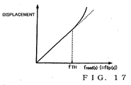
- Fig. 17 is graph showing relationship between the pressing force freed(x) acting on the reed MR and the displacement (amount) of the reed MR.
- a predetermined value fTH i.e. once the pressing force freed(x) reaches the elasticity limit
- the displacement of the reed MR changes non-linearly. Namely, as the intensity of the pressing force freed(x) increases, the spring constant klip(x) (x, flip(x)) decreases (i.e., the reed MR becomes easier to deform).
- the pressing force freed(x) acting from the lip ML on the reed MR is equal to the pressing force flip(x) acting from the reed MR on the lip ML
- the pressing force freed(x) is written as the pressing force flip(x), for convenience sake, in the following description.
- the internal resistance ⁇ lip(x, flip(x)) of the lip ML is defined by Equation (a3 - 2) below. Because the spring constant klip(x) (x, flip(x)) in Equation (a3 - 2) is a function of the pressing force flip(x), the internal resistance ⁇ lip(x, flip(x)) changes in accordance with the position x and pressing force flip(x). Similarly, the internal resistance ⁇ reed(x, flip(x)) of the reed MR changes in accordance with the position x and pressing force flip(x) (spring constant kreed(x, flip(x)), as defined by Equation (a4 - 2) below.
- Fig. 18 is a block diagram showing the characteristic parameter conversion section 21 employed in the fourth embodiment.
- the characteristic parameter conversion section 21 has two types of tables (Tlip, Treed).
- the table Tlip correlates values of the pressing force flip(x) and the spring constant klip(x) (x, flip(x)) of the lip ML to each other
- the table Treed correlates values of the pressing force flip(x) and the spring constant kreed(x) (x, flip(x)) of the reed MR to each other.
- Contents of the table Tlip and table Treed are set in accordance with results of experiments where pressing force was applied to an actual lip and reed.
- the characteristic parameter conversion section 21 searches through the table Tlip for a spring constant klip(x) (x, flip(x)) corresponding to pressing force flip(x) per unit length calculated by dividing pressing force Flip(x), calculated through a key scale process, by a length lteeth of the teeth MT, and then searches through the table Treed for a spring constant kreed(x) (x, flip(x)) corresponding to the pressing force flip(x).
- the characteristic parameter conversion section 21 calculates internal resistance ⁇ lip(x, flip(x)) corresponding to the position x and pressing force flip(x) by performing the arithmetic operation of Equation (a3 - 2) with respect to the spring constant klip(x) (x, flip(x)) searched out from the table Tlip and physical property values (mlip and tan ⁇ lip) of the lip ML.
- the distribution of mass mlip(x) in Equation (a3 - 2) above is a result of multiplication between the horizontal width blip(x) and the density ⁇ lip.
- the characteristic parameter conversion section 21 calculates internal resistance ⁇ reed(x, flip(x)) corresponding to the position x and pressing force flip(x) by performing the arithmetic operation of Equation (a4 - 2) with respect to the spring constant kreed(x) (x, flip(x)) searched out from the table Treed and physical property values and dimension (tan ⁇ reed, ⁇ reed and A(x)) of the reed MR.
- Fig. 12 illustratively shows the construction where parameters pertaining to the embouchure and fingering are calculated through the key scale process, there may be employed an alternative construction where such parameters pertaining to the embouchure and fingering are input or designated directly to the arithmetic operation processing device 10 by the user via the input device 44.
- bending rigidity Still(x) of the reed MR is determined from results of actual measurements.
- bending rigidity Still(x) is determined from displacement of a test piece, simulating the reed MR, measured with pressing force applied to various positions x of the test piece, and then a function (hereinafter "rigidity function") approximating relationship between the position x and the bending rigidity Still(x) is created.
- Such rigidity functions of a plurality of types of reeds MR, differing in physical property value and dimension, are sequentially created in the aforementioned manner and stored into the storage device 42.
- the reed simulating section 31 (more specifically, the first and second arithmetic operation sections 311 and 312) of the arithmetic operation processing device 10 acquires, from the storage device 42, rigidity function corresponding to any one of the reeds MR (e.g., reed MR selected by the user) and uses the acquired rigidity function in subsequent arithmetic operations.
- Such arrangements too can achieve substantially the same advantageous benefits as the first and second embodiments.
- Tone synthesis based on the displacement y(x, t) calculated by the second arithmetic operation section 312 may be performed in any desired manner. For example, there may be employed a construction where simulation of sound wave losses in tone holes and boundary between inside and outside of the bell is omitted.
Landscapes
- Physics & Mathematics (AREA)
- Nonlinear Science (AREA)
- Engineering & Computer Science (AREA)
- Acoustics & Sound (AREA)
- Multimedia (AREA)
- Electrophonic Musical Instruments (AREA)
- Aerodynamic Tests, Hydrodynamic Tests, Wind Tunnels, And Water Tanks (AREA)
- Wind Motors (AREA)
Claims (8)
- Vorrichtung zur Synthese eines Tons eines Blasinstruments, der ansprechend auf eine Vibration eines Blättchens erzeugt wird, das eine Lippe während einer Darbietung des Blasinstrumentes kontaktiert, wobei die Vorrichtung Folgendes aufweist:einen ersten Rechenoperationsabschnitt (31, 311), der eine erste Bewegungsgleichung (A1) löst, die repräsentativ für ein Verhalten des Blättchens in einem Gleichgewichtszustand ist, in dem eine externe Kraft auf die Lippe einwirkt, sowie eine zweite Bewegungsgleichung (A2), die repräsentativ für das Verhalten der Lippe in dem Gleichgewichtszustand ist, um dadurch einen Versatz der Lippe und einen Versatz des Blättchens im Gleichgewichtszustand zu berechnen;einen zweiten Rechenoperationsabschnitt (31, 312), der eine Bewegungsgleichung (B) der gekoppelten Vibration der Lippe und des Blättchens löst, wobei die Berechnungsergebnisse des ersten Rechenoperationsabschnitts (31, 311) als Ausgangswerte des Versatzes der Lippe und des Versatzes des Blättchens verwendet werden, um dadurch den Versatz des Blättchens zu berechnen; undeinen Tonsyntheseabschnitt (31, 313, 314, 33, 35), der einen Ton auf der Basis des Versatzes synthetisiert, der durch den zweiten Rechenoperationsabschnitt (31, 312) berechnet wird;dadurch gekennzeichnet, dass die erste Bewegungsgleichung (A1) und die zweite Bewegungsgleichung (A2) eine Federkonstante der Lippe aufweisen, die sich gemäß einer Position der Lippe und der Intensität der Andruckkraft verändert, die auf die Lippe einwirkt.
- Vorrichtung gemäß Anspruch 1, wobei jedes Mal, wenn sich die Intensität der externen Kraft verändert, die auf die Lippe einwirkt,
der erste Rechenoperationsabschnitt (31, 311) den Versatz der Lippe entsprechend der veränderten Intensität der externen Kraft berechnet, und zwar auf der Basis der ersten Bewegungsgleichung (A1) und der zweiten Bewegungsgleichung (A2), und
der zweite Rechenoperationsabschnitt (31, 312) den Versatz des Blättchens berechnet, und zwar durch Substituieren des Versatzes der Lippe, der durch den ersten Rechenoperationsabschnitt (31, 311) berechnet wird, in die Bewegungsgleichung (B) der gekoppelten Vibration. - Vorrichtung gemäß Anspruch 1 oder 2, wobei die erste Bewegungsgleichung (A1) eine Biegesteifigkeit aufweist, die sich gemäß einer Position des Blättchens verändert.
- Vorrichtung gemäß einem der Ansprüche 1-3, wobei der zweite Rechenoperationsabschnitt (31, 312) den Versatz des Blättchens auf einen vorbestimmten Bereich begrenzt.
- Vorrichtung gemäß einem der Ansprüche 1-4, wobei die Bewegungsgleichung (B) der gekoppelten Vibration entweder den Innenwiderstand der Lippe, der sich gemäß einer Position in der Lippe verändert, und/oder den Innenwiderstand des Blättchens aufweist, der sich gemäß einer Position in dem Blättchen verändert.
- Vorrichtung gemäß einem der Ansprüche 1-4, wobei die Bewegungsgleichung (B) der gekoppelten Vibration den Innenwiderstand der Lippe, der sich gemäß einer Position in der Lippe verändert, und/oder die Andruckkraft, die auf die Lippe einwirkt, und/oder den Innenwiderstand des Blättchens aufweist, der sich gemäß einer Position in dem Blättchen und der Andruckkraft verändert, die auf das Blättchen einwirkt.
- Verfahren, das durch einen Computer ausgeführt wird, um einen Ton eines Blasinstruments zu synthetisieren, der ansprechend auf eine Vibration eines Blättchens erzeugt wird, das eine Lippe während einer Darbietung des Blasinstruments kontaktiert, wobei das Verfahren Folgendes aufweist:einen ersten Rechenoperationsschritt zum Lösen einer ersten Bewegungsgleichung (A1), die repräsentativ für ein Verhalten des Blättchens in einem Gleichgewichtszustand ist, in dem eine externe Kraft auf die Lippe einwirkt, sowie einer zweiten Bewegungsgleichung (A2), die repräsentativ für das Verhalten der Lippe in dem Gleichgewichtszustand ist, um dadurch den Versatz der Lippe und den Versatz des Blättchens in dem Gleichgewichtszustand zu berechnen;einen zweiten Rechenoperationsschritt zum Lösen einer Bewegungsgleichung (B) der gekoppelten Vibration der Lippe und des Blättchens, wobei die Berechnungsergebnisse des ersten Rechenoperationsschritts als Ausgangswerte des Versatzes der Lippe und des Versatzes des Blättchens verwendet werden, um dadurch den Versatz des Blättchens zu berechnen; und einen Tonsyntheseschritt des Synthetisierens eines Tons auf der Basis des Versatzes, der durch den zweiten Rechenoperationsschritt berechnet wird;dadurch gekennzeichnet, dass die erste Bewegungsgleichung (A1) und die zweite Bewegungsgleichung (A2) eine Federkonstante der Lippe aufweisen, die sich gemäß einer Position der Lippe und der Intensität der Andruckkraft verändert, die auf die Lippe einwirkt.
- Computerlesbares Medium, das ein Programm speichert, das durch einen Computer ausgeführt werden kann, um einen Ton eines Blasinstruments zu synthetisieren, der ansprechend auf eine Vibration eines Blättchens erzeugt wird, das eine Lippe während einer Darbietung des Blasinstruments kontaktiert, wobei das Verfahren Folgendes aufweist:einen ersten Rechenoperationsschritt zum Lösen einer ersten Bewegungsgleichung, die repräsentativ für ein Verhalten des Blättchens in einem Gleichgewichtszustand ist, wobei eine externe Kraft auf die Lippe einwirkt, sowie einer zweiten Bewegungsgleichung, die repräsentativ für das Verhalten der Lippe in dem Gleichgewichtszustand ist, um dadurch den Versatz der Lippe und den Versatz des Blättchens im Gleichgewichtszustand zu berechnen;einen zweiten Rechenoperationsschritt zum Lösen einer Bewegungsgleichung der gekoppelten Vibration der Lippe und des Blättchens, wobei die Berechnungsergebnisse des ersten Rechenoperationsschritts als Ausgangswerte des Versatzes der Lippe und des Versatzes des Blättchens verwendet werden, um dadurch den Versatz des Blättchens zu berechnen; undeinen Tonsyntheseschritt des Synthetisierens eines Tons auf der Basis des Versatzes, der durch den zweiten Rechenoperationsschritt berechnet wird; dadurch gekennzeichnet, dass die erste Bewegungsgleichung (A1) und die zweite Bewegungsgleichung (A2) eine Federkonstante der Lippe aufweisen, die sich gemäß einer Position der Lippe und der Intensität der Andruckkraft verändert, die auf die Lippe einwirkt.
Applications Claiming Priority (2)
| Application Number | Priority Date | Filing Date | Title |
|---|---|---|---|
| JP2008003383 | 2008-01-10 | ||
| JP2008120311A JP5332296B2 (ja) | 2008-01-10 | 2008-05-02 | 楽音合成装置およびプログラム |
Publications (3)
| Publication Number | Publication Date |
|---|---|
| EP2079080A2 EP2079080A2 (de) | 2009-07-15 |
| EP2079080A3 EP2079080A3 (de) | 2014-12-24 |
| EP2079080B1 true EP2079080B1 (de) | 2016-03-23 |
Family
ID=40380198
Family Applications (1)
| Application Number | Title | Priority Date | Filing Date |
|---|---|---|---|
| EP09000251.0A Not-in-force EP2079080B1 (de) | 2008-01-10 | 2009-01-09 | Vorrichtung und Verfahren zur Tonsynthese |
Country Status (1)
| Country | Link |
|---|---|
| EP (1) | EP2079080B1 (de) |
-
2009
- 2009-01-09 EP EP09000251.0A patent/EP2079080B1/de not_active Not-in-force
Also Published As
| Publication number | Publication date |
|---|---|
| EP2079080A2 (de) | 2009-07-15 |
| EP2079080A3 (de) | 2014-12-24 |
Similar Documents
| Publication | Publication Date | Title |
|---|---|---|
| Keefe | Woodwind air column models | |
| Chatziioannou et al. | Investigating clarinet articulation using a physical model and an artificial blowing machine | |
| US10170094B2 (en) | Musical sound generating device, control method for same, storage medium, and electronic musical instrument | |
| JP2018106006A (ja) | 楽音生成装置および方法、電子楽器 | |
| JP2679275B2 (ja) | 楽音合成装置 | |
| Petersen et al. | The effect of the cutoff frequency on the sound production of a clarinet-like instrument | |
| Elliott et al. | Input and transfer response of brass wind instruments | |
| US5272275A (en) | Brass instrument type tone synthesizer | |
| US7872190B2 (en) | Tone synthesis apparatus and method | |
| Almeida et al. | The mechanism producing initial transients on the clarinet | |
| Avanzini et al. | Musical instrument modeling: the case of the piano | |
| Chatziioannou et al. | Inverse modelling of clarinet performance | |
| EP2079080A2 (de) | Vorrichtung und Verfahren zur Tonsynthese | |
| JP5531382B2 (ja) | 楽音合成装置、楽音合成システムおよびプログラム | |
| JP3459948B2 (ja) | 楽音合成装置 | |
| Resch et al. | Three-dimensional simulations of sound propagation in a trumpet with accurate mouthpiece shank geometry | |
| JPH0452697A (ja) | 楽音合成装置 | |
| JP3042314B2 (ja) | 楽音信号発生装置 | |
| JP5182484B2 (ja) | 楽音合成装置およびプログラム | |
| Mohapatra et al. | 2.5 D Vocal Tract Modeling: Bridging Low-Dimensional Efficiency with 3D Accuracy. | |
| JP2841847B2 (ja) | 楽音合成装置 | |
| Bonilla | Sound Synthesis of a Colombian Gaita by Means of Physical Modeling | |
| JP2010271373A (ja) | 楽音合成装置および変数設定装置 | |
| Gomez Bonilla | Sound Synthesis of a Colombian Gaita by Means of Physical Modeling | |
| Acker et al. | Discrimination of musical chord components |
Legal Events
| Date | Code | Title | Description |
|---|---|---|---|
| PUAI | Public reference made under article 153(3) epc to a published international application that has entered the european phase |
Free format text: ORIGINAL CODE: 0009012 |
|
| AK | Designated contracting states |
Kind code of ref document: A2 Designated state(s): AT BE BG CH CY CZ DE DK EE ES FI FR GB GR HR HU IE IS IT LI LT LU LV MC MK MT NL NO PL PT RO SE SI SK TR |
|
| AX | Request for extension of the european patent |
Extension state: AL BA RS |
|
| PUAL | Search report despatched |
Free format text: ORIGINAL CODE: 0009013 |
|
| AK | Designated contracting states |
Kind code of ref document: A3 Designated state(s): AT BE BG CH CY CZ DE DK EE ES FI FR GB GR HR HU IE IS IT LI LT LU LV MC MK MT NL NO PL PT RO SE SI SK TR |
|
| AX | Request for extension of the european patent |
Extension state: AL BA RS |
|
| RIC1 | Information provided on ipc code assigned before grant |
Ipc: G10H 5/00 20060101AFI20141118BHEP |
|
| 17P | Request for examination filed |
Effective date: 20150624 |
|
| RBV | Designated contracting states (corrected) |
Designated state(s): AT BE BG CH CY CZ DE DK EE ES FI FR GB GR HR HU IE IS IT LI LT LU LV MC MK MT NL NO PL PT RO SE SI SK TR |
|
| GRAP | Despatch of communication of intention to grant a patent |
Free format text: ORIGINAL CODE: EPIDOSNIGR1 |
|
| AKX | Designation fees paid |
Designated state(s): AT BE BG CH CY CZ DE DK EE ES FI FR GB GR HR HU IE IS IT LI LT LU LV MC MK MT NL NO PL PT RO SE SI SK TR |
|
| AXX | Extension fees paid |
Extension state: AL Extension state: BA Extension state: RS |
|
| INTG | Intention to grant announced |
Effective date: 20150828 |
|
| GRAS | Grant fee paid |
Free format text: ORIGINAL CODE: EPIDOSNIGR3 |
|
| GRAA | (expected) grant |
Free format text: ORIGINAL CODE: 0009210 |
|
| AK | Designated contracting states |
Kind code of ref document: B1 Designated state(s): AT BE BG CH CY CZ DE DK EE ES FI FR GB GR HR HU IE IS IT LI LT LU LV MC MK MT NL NO PL PT RO SE SI SK TR |
|
| REG | Reference to a national code |
Ref country code: GB Ref legal event code: FG4D |
|
| REG | Reference to a national code |
Ref country code: CH Ref legal event code: EP |
|
| REG | Reference to a national code |
Ref country code: AT Ref legal event code: REF Ref document number: 783822 Country of ref document: AT Kind code of ref document: T Effective date: 20160415 |
|
| REG | Reference to a national code |
Ref country code: IE Ref legal event code: FG4D |
|
| REG | Reference to a national code |
Ref country code: DE Ref legal event code: R096 Ref document number: 602009036912 Country of ref document: DE |
|
| REG | Reference to a national code |
Ref country code: LT Ref legal event code: MG4D |
|
| REG | Reference to a national code |
Ref country code: NL Ref legal event code: MP Effective date: 20160323 |
|
| PG25 | Lapsed in a contracting state [announced via postgrant information from national office to epo] |
Ref country code: NO Free format text: LAPSE BECAUSE OF FAILURE TO SUBMIT A TRANSLATION OF THE DESCRIPTION OR TO PAY THE FEE WITHIN THE PRESCRIBED TIME-LIMIT Effective date: 20160623 Ref country code: FI Free format text: LAPSE BECAUSE OF FAILURE TO SUBMIT A TRANSLATION OF THE DESCRIPTION OR TO PAY THE FEE WITHIN THE PRESCRIBED TIME-LIMIT Effective date: 20160323 Ref country code: GR Free format text: LAPSE BECAUSE OF FAILURE TO SUBMIT A TRANSLATION OF THE DESCRIPTION OR TO PAY THE FEE WITHIN THE PRESCRIBED TIME-LIMIT Effective date: 20160624 |
|
| REG | Reference to a national code |
Ref country code: AT Ref legal event code: MK05 Ref document number: 783822 Country of ref document: AT Kind code of ref document: T Effective date: 20160323 |
|
| PG25 | Lapsed in a contracting state [announced via postgrant information from national office to epo] |
Ref country code: LT Free format text: LAPSE BECAUSE OF FAILURE TO SUBMIT A TRANSLATION OF THE DESCRIPTION OR TO PAY THE FEE WITHIN THE PRESCRIBED TIME-LIMIT Effective date: 20160323 Ref country code: NL Free format text: LAPSE BECAUSE OF FAILURE TO SUBMIT A TRANSLATION OF THE DESCRIPTION OR TO PAY THE FEE WITHIN THE PRESCRIBED TIME-LIMIT Effective date: 20160323 Ref country code: SE Free format text: LAPSE BECAUSE OF FAILURE TO SUBMIT A TRANSLATION OF THE DESCRIPTION OR TO PAY THE FEE WITHIN THE PRESCRIBED TIME-LIMIT Effective date: 20160323 Ref country code: LV Free format text: LAPSE BECAUSE OF FAILURE TO SUBMIT A TRANSLATION OF THE DESCRIPTION OR TO PAY THE FEE WITHIN THE PRESCRIBED TIME-LIMIT Effective date: 20160323 |
|
| PG25 | Lapsed in a contracting state [announced via postgrant information from national office to epo] |
Ref country code: EE Free format text: LAPSE BECAUSE OF FAILURE TO SUBMIT A TRANSLATION OF THE DESCRIPTION OR TO PAY THE FEE WITHIN THE PRESCRIBED TIME-LIMIT Effective date: 20160323 Ref country code: PL Free format text: LAPSE BECAUSE OF FAILURE TO SUBMIT A TRANSLATION OF THE DESCRIPTION OR TO PAY THE FEE WITHIN THE PRESCRIBED TIME-LIMIT Effective date: 20160323 Ref country code: IS Free format text: LAPSE BECAUSE OF FAILURE TO SUBMIT A TRANSLATION OF THE DESCRIPTION OR TO PAY THE FEE WITHIN THE PRESCRIBED TIME-LIMIT Effective date: 20160723 |
|
| PG25 | Lapsed in a contracting state [announced via postgrant information from national office to epo] |
Ref country code: AT Free format text: LAPSE BECAUSE OF FAILURE TO SUBMIT A TRANSLATION OF THE DESCRIPTION OR TO PAY THE FEE WITHIN THE PRESCRIBED TIME-LIMIT Effective date: 20160323 Ref country code: RO Free format text: LAPSE BECAUSE OF FAILURE TO SUBMIT A TRANSLATION OF THE DESCRIPTION OR TO PAY THE FEE WITHIN THE PRESCRIBED TIME-LIMIT Effective date: 20160323 Ref country code: ES Free format text: LAPSE BECAUSE OF FAILURE TO SUBMIT A TRANSLATION OF THE DESCRIPTION OR TO PAY THE FEE WITHIN THE PRESCRIBED TIME-LIMIT Effective date: 20160323 Ref country code: PT Free format text: LAPSE BECAUSE OF FAILURE TO SUBMIT A TRANSLATION OF THE DESCRIPTION OR TO PAY THE FEE WITHIN THE PRESCRIBED TIME-LIMIT Effective date: 20160725 Ref country code: SK Free format text: LAPSE BECAUSE OF FAILURE TO SUBMIT A TRANSLATION OF THE DESCRIPTION OR TO PAY THE FEE WITHIN THE PRESCRIBED TIME-LIMIT Effective date: 20160323 Ref country code: CZ Free format text: LAPSE BECAUSE OF FAILURE TO SUBMIT A TRANSLATION OF THE DESCRIPTION OR TO PAY THE FEE WITHIN THE PRESCRIBED TIME-LIMIT Effective date: 20160323 |
|
| PG25 | Lapsed in a contracting state [announced via postgrant information from national office to epo] |
Ref country code: BE Free format text: LAPSE BECAUSE OF FAILURE TO SUBMIT A TRANSLATION OF THE DESCRIPTION OR TO PAY THE FEE WITHIN THE PRESCRIBED TIME-LIMIT Effective date: 20160323 Ref country code: IT Free format text: LAPSE BECAUSE OF FAILURE TO SUBMIT A TRANSLATION OF THE DESCRIPTION OR TO PAY THE FEE WITHIN THE PRESCRIBED TIME-LIMIT Effective date: 20160323 |
|
| REG | Reference to a national code |
Ref country code: DE Ref legal event code: R097 Ref document number: 602009036912 Country of ref document: DE |
|
| PLBE | No opposition filed within time limit |
Free format text: ORIGINAL CODE: 0009261 |
|
| STAA | Information on the status of an ep patent application or granted ep patent |
Free format text: STATUS: NO OPPOSITION FILED WITHIN TIME LIMIT |
|
| PG25 | Lapsed in a contracting state [announced via postgrant information from national office to epo] |
Ref country code: DK Free format text: LAPSE BECAUSE OF FAILURE TO SUBMIT A TRANSLATION OF THE DESCRIPTION OR TO PAY THE FEE WITHIN THE PRESCRIBED TIME-LIMIT Effective date: 20160323 |
|
| PG25 | Lapsed in a contracting state [announced via postgrant information from national office to epo] |
Ref country code: BG Free format text: LAPSE BECAUSE OF FAILURE TO SUBMIT A TRANSLATION OF THE DESCRIPTION OR TO PAY THE FEE WITHIN THE PRESCRIBED TIME-LIMIT Effective date: 20160623 |
|
| 26N | No opposition filed |
Effective date: 20170102 |
|
| PG25 | Lapsed in a contracting state [announced via postgrant information from national office to epo] |
Ref country code: SI Free format text: LAPSE BECAUSE OF FAILURE TO SUBMIT A TRANSLATION OF THE DESCRIPTION OR TO PAY THE FEE WITHIN THE PRESCRIBED TIME-LIMIT Effective date: 20160323 |
|
| REG | Reference to a national code |
Ref country code: CH Ref legal event code: PL |
|
| PG25 | Lapsed in a contracting state [announced via postgrant information from national office to epo] |
Ref country code: MC Free format text: LAPSE BECAUSE OF FAILURE TO SUBMIT A TRANSLATION OF THE DESCRIPTION OR TO PAY THE FEE WITHIN THE PRESCRIBED TIME-LIMIT Effective date: 20160323 |
|
| REG | Reference to a national code |
Ref country code: FR Ref legal event code: ST Effective date: 20170929 |
|
| PG25 | Lapsed in a contracting state [announced via postgrant information from national office to epo] |
Ref country code: CH Free format text: LAPSE BECAUSE OF NON-PAYMENT OF DUE FEES Effective date: 20170131 Ref country code: LI Free format text: LAPSE BECAUSE OF NON-PAYMENT OF DUE FEES Effective date: 20170131 Ref country code: FR Free format text: LAPSE BECAUSE OF NON-PAYMENT OF DUE FEES Effective date: 20170131 |
|
| REG | Reference to a national code |
Ref country code: IE Ref legal event code: MM4A |
|
| PG25 | Lapsed in a contracting state [announced via postgrant information from national office to epo] |
Ref country code: LU Free format text: LAPSE BECAUSE OF NON-PAYMENT OF DUE FEES Effective date: 20170109 |
|
| PG25 | Lapsed in a contracting state [announced via postgrant information from national office to epo] |
Ref country code: IE Free format text: LAPSE BECAUSE OF NON-PAYMENT OF DUE FEES Effective date: 20170109 |
|
| PGFP | Annual fee paid to national office [announced via postgrant information from national office to epo] |
Ref country code: GB Payment date: 20180103 Year of fee payment: 10 |
|
| PG25 | Lapsed in a contracting state [announced via postgrant information from national office to epo] |
Ref country code: MT Free format text: LAPSE BECAUSE OF NON-PAYMENT OF DUE FEES Effective date: 20170109 |
|
| PGFP | Annual fee paid to national office [announced via postgrant information from national office to epo] |
Ref country code: DE Payment date: 20190123 Year of fee payment: 11 |
|
| PG25 | Lapsed in a contracting state [announced via postgrant information from national office to epo] |
Ref country code: HU Free format text: LAPSE BECAUSE OF FAILURE TO SUBMIT A TRANSLATION OF THE DESCRIPTION OR TO PAY THE FEE WITHIN THE PRESCRIBED TIME-LIMIT; INVALID AB INITIO Effective date: 20090109 |
|
| GBPC | Gb: european patent ceased through non-payment of renewal fee |
Effective date: 20190109 |
|
| PG25 | Lapsed in a contracting state [announced via postgrant information from national office to epo] |
Ref country code: CY Free format text: LAPSE BECAUSE OF NON-PAYMENT OF DUE FEES Effective date: 20160323 |
|
| PG25 | Lapsed in a contracting state [announced via postgrant information from national office to epo] |
Ref country code: MK Free format text: LAPSE BECAUSE OF FAILURE TO SUBMIT A TRANSLATION OF THE DESCRIPTION OR TO PAY THE FEE WITHIN THE PRESCRIBED TIME-LIMIT Effective date: 20160323 |
|
| PG25 | Lapsed in a contracting state [announced via postgrant information from national office to epo] |
Ref country code: GB Free format text: LAPSE BECAUSE OF NON-PAYMENT OF DUE FEES Effective date: 20190109 |
|
| PG25 | Lapsed in a contracting state [announced via postgrant information from national office to epo] |
Ref country code: TR Free format text: LAPSE BECAUSE OF FAILURE TO SUBMIT A TRANSLATION OF THE DESCRIPTION OR TO PAY THE FEE WITHIN THE PRESCRIBED TIME-LIMIT Effective date: 20160323 |
|
| PG25 | Lapsed in a contracting state [announced via postgrant information from national office to epo] |
Ref country code: HR Free format text: LAPSE BECAUSE OF FAILURE TO SUBMIT A TRANSLATION OF THE DESCRIPTION OR TO PAY THE FEE WITHIN THE PRESCRIBED TIME-LIMIT Effective date: 20160323 |
|
| REG | Reference to a national code |
Ref country code: DE Ref legal event code: R119 Ref document number: 602009036912 Country of ref document: DE |
|
| PG25 | Lapsed in a contracting state [announced via postgrant information from national office to epo] |
Ref country code: DE Free format text: LAPSE BECAUSE OF NON-PAYMENT OF DUE FEES Effective date: 20200801 |