EP2078855A1 - Anneau de support pour assembler un roulement ou une pièce de roulement dans une unité d'embrayage - Google Patents
Anneau de support pour assembler un roulement ou une pièce de roulement dans une unité d'embrayage Download PDFInfo
- Publication number
- EP2078855A1 EP2078855A1 EP08075022A EP08075022A EP2078855A1 EP 2078855 A1 EP2078855 A1 EP 2078855A1 EP 08075022 A EP08075022 A EP 08075022A EP 08075022 A EP08075022 A EP 08075022A EP 2078855 A1 EP2078855 A1 EP 2078855A1
- Authority
- EP
- European Patent Office
- Prior art keywords
- supporting ring
- bearing
- beams
- ring
- gear unit
- Prior art date
- Legal status (The legal status is an assumption and is not a legal conclusion. Google has not performed a legal analysis and makes no representation as to the accuracy of the status listed.)
- Withdrawn
Links
Images


Classifications
-
- F—MECHANICAL ENGINEERING; LIGHTING; HEATING; WEAPONS; BLASTING
- F16—ENGINEERING ELEMENTS AND UNITS; GENERAL MEASURES FOR PRODUCING AND MAINTAINING EFFECTIVE FUNCTIONING OF MACHINES OR INSTALLATIONS; THERMAL INSULATION IN GENERAL
- F16F—SPRINGS; SHOCK-ABSORBERS; MEANS FOR DAMPING VIBRATION
- F16F1/00—Springs
- F16F1/02—Springs made of steel or other material having low internal friction; Wound, torsion, leaf, cup, ring or the like springs, the material of the spring not being relevant
- F16F1/32—Belleville-type springs
- F16F1/324—Belleville-type springs characterised by having tongues or arms directed in a generally radial direction, i.e. diaphragm-type springs
-
- F—MECHANICAL ENGINEERING; LIGHTING; HEATING; WEAPONS; BLASTING
- F03—MACHINES OR ENGINES FOR LIQUIDS; WIND, SPRING, OR WEIGHT MOTORS; PRODUCING MECHANICAL POWER OR A REACTIVE PROPULSIVE THRUST, NOT OTHERWISE PROVIDED FOR
- F03D—WIND MOTORS
- F03D15/00—Transmission of mechanical power
-
- F—MECHANICAL ENGINEERING; LIGHTING; HEATING; WEAPONS; BLASTING
- F03—MACHINES OR ENGINES FOR LIQUIDS; WIND, SPRING, OR WEIGHT MOTORS; PRODUCING MECHANICAL POWER OR A REACTIVE PROPULSIVE THRUST, NOT OTHERWISE PROVIDED FOR
- F03D—WIND MOTORS
- F03D80/00—Details, components or accessories not provided for in groups F03D1/00 - F03D17/00
- F03D80/70—Bearing or lubricating arrangements
-
- F—MECHANICAL ENGINEERING; LIGHTING; HEATING; WEAPONS; BLASTING
- F16—ENGINEERING ELEMENTS AND UNITS; GENERAL MEASURES FOR PRODUCING AND MAINTAINING EFFECTIVE FUNCTIONING OF MACHINES OR INSTALLATIONS; THERMAL INSULATION IN GENERAL
- F16C—SHAFTS; FLEXIBLE SHAFTS; ELEMENTS OR CRANKSHAFT MECHANISMS; ROTARY BODIES OTHER THAN GEARING ELEMENTS; BEARINGS
- F16C27/00—Elastic or yielding bearings or bearing supports, for exclusively rotary movement
- F16C27/04—Ball or roller bearings, e.g. with resilient rolling bodies
-
- F—MECHANICAL ENGINEERING; LIGHTING; HEATING; WEAPONS; BLASTING
- F03—MACHINES OR ENGINES FOR LIQUIDS; WIND, SPRING, OR WEIGHT MOTORS; PRODUCING MECHANICAL POWER OR A REACTIVE PROPULSIVE THRUST, NOT OTHERWISE PROVIDED FOR
- F03D—WIND MOTORS
- F03D15/00—Transmission of mechanical power
- F03D15/10—Transmission of mechanical power using gearing not limited to rotary motion, e.g. with oscillating or reciprocating members
-
- F—MECHANICAL ENGINEERING; LIGHTING; HEATING; WEAPONS; BLASTING
- F03—MACHINES OR ENGINES FOR LIQUIDS; WIND, SPRING, OR WEIGHT MOTORS; PRODUCING MECHANICAL POWER OR A REACTIVE PROPULSIVE THRUST, NOT OTHERWISE PROVIDED FOR
- F03D—WIND MOTORS
- F03D9/00—Adaptations of wind motors for special use; Combinations of wind motors with apparatus driven thereby; Wind motors specially adapted for installation in particular locations
- F03D9/20—Wind motors characterised by the driven apparatus
- F03D9/25—Wind motors characterised by the driven apparatus the apparatus being an electrical generator
-
- F—MECHANICAL ENGINEERING; LIGHTING; HEATING; WEAPONS; BLASTING
- F05—INDEXING SCHEMES RELATING TO ENGINES OR PUMPS IN VARIOUS SUBCLASSES OF CLASSES F01-F04
- F05B—INDEXING SCHEME RELATING TO WIND, SPRING, WEIGHT, INERTIA OR LIKE MOTORS, TO MACHINES OR ENGINES FOR LIQUIDS COVERED BY SUBCLASSES F03B, F03D AND F03G
- F05B2240/00—Components
- F05B2240/50—Bearings
-
- F—MECHANICAL ENGINEERING; LIGHTING; HEATING; WEAPONS; BLASTING
- F05—INDEXING SCHEMES RELATING TO ENGINES OR PUMPS IN VARIOUS SUBCLASSES OF CLASSES F01-F04
- F05B—INDEXING SCHEME RELATING TO WIND, SPRING, WEIGHT, INERTIA OR LIKE MOTORS, TO MACHINES OR ENGINES FOR LIQUIDS COVERED BY SUBCLASSES F03B, F03D AND F03G
- F05B2280/00—Materials; Properties thereof
- F05B2280/50—Intrinsic material properties or characteristics
- F05B2280/5001—Elasticity
-
- F—MECHANICAL ENGINEERING; LIGHTING; HEATING; WEAPONS; BLASTING
- F05—INDEXING SCHEMES RELATING TO ENGINES OR PUMPS IN VARIOUS SUBCLASSES OF CLASSES F01-F04
- F05C—INDEXING SCHEME RELATING TO MATERIALS, MATERIAL PROPERTIES OR MATERIAL CHARACTERISTICS FOR MACHINES, ENGINES OR PUMPS OTHER THAN NON-POSITIVE-DISPLACEMENT MACHINES OR ENGINES
- F05C2251/00—Material properties
- F05C2251/02—Elasticity
-
- F—MECHANICAL ENGINEERING; LIGHTING; HEATING; WEAPONS; BLASTING
- F16—ENGINEERING ELEMENTS AND UNITS; GENERAL MEASURES FOR PRODUCING AND MAINTAINING EFFECTIVE FUNCTIONING OF MACHINES OR INSTALLATIONS; THERMAL INSULATION IN GENERAL
- F16C—SHAFTS; FLEXIBLE SHAFTS; ELEMENTS OR CRANKSHAFT MECHANISMS; ROTARY BODIES OTHER THAN GEARING ELEMENTS; BEARINGS
- F16C2360/00—Engines or pumps
- F16C2360/31—Wind motors
-
- F—MECHANICAL ENGINEERING; LIGHTING; HEATING; WEAPONS; BLASTING
- F16—ENGINEERING ELEMENTS AND UNITS; GENERAL MEASURES FOR PRODUCING AND MAINTAINING EFFECTIVE FUNCTIONING OF MACHINES OR INSTALLATIONS; THERMAL INSULATION IN GENERAL
- F16C—SHAFTS; FLEXIBLE SHAFTS; ELEMENTS OR CRANKSHAFT MECHANISMS; ROTARY BODIES OTHER THAN GEARING ELEMENTS; BEARINGS
- F16C2361/00—Apparatus or articles in engineering in general
- F16C2361/61—Toothed gear systems, e.g. support of pinion shafts
-
- Y—GENERAL TAGGING OF NEW TECHNOLOGICAL DEVELOPMENTS; GENERAL TAGGING OF CROSS-SECTIONAL TECHNOLOGIES SPANNING OVER SEVERAL SECTIONS OF THE IPC; TECHNICAL SUBJECTS COVERED BY FORMER USPC CROSS-REFERENCE ART COLLECTIONS [XRACs] AND DIGESTS
- Y02—TECHNOLOGIES OR APPLICATIONS FOR MITIGATION OR ADAPTATION AGAINST CLIMATE CHANGE
- Y02E—REDUCTION OF GREENHOUSE GAS [GHG] EMISSIONS, RELATED TO ENERGY GENERATION, TRANSMISSION OR DISTRIBUTION
- Y02E10/00—Energy generation through renewable energy sources
- Y02E10/70—Wind energy
- Y02E10/72—Wind turbines with rotation axis in wind direction
Definitions
- the present invention relates to a supporting ring for mounting a bearing or bearing parts in a gear unit.
- the present invention relates to such a supporting ring for application in a wind turbine, typically for mounting the bearing of the second planet carrier of a double stage planetary gear unit connecting the rotor hub of the wind turbine to a generator.
- the bearing is located by preventing the movement of the outer bearing ring and/or the inner bearing ring.
- Typical examples are: the fixing of an inner bearing ring on a shaft through a shrinking process, the bolting of the outer ring to the housing, the use of nuts and split pins to prevent the movement of one of the rings, etc...
- the loads acting on the rotating part can be easily transferred to the housing, as for example loads due to the weight, but also dynamic loads.
- the rotor hub is supported by a couple of bearings or occasionally by one main bearing.
- This rotor hub is connected to a gear box, typically having one or more planetary stages, in which the slow rotation of the rotor blades is transformed in a fast rotation at the output of the gearbox, the output being connected to a power generator.
- the planet carrier of the first planetary gear stage is normally connected to the rotor hub, the planet carrier being supported by its own bearing or pair of bearings.
- One way of integrating parts is to use one main bearing or a pair of bearings which supports the planet carrier as well as the rotor hub, whereby on this rotor hub in the newest designs rotor blades can be mounted with a length of 70 m.
- the output shaft of the first planetary gear stage is held centrally through the interaction of the sun wheel with the planet wheels of the first planetary gear stage also without any additional direct bearing.
- this output shaft of the first planetary gear stage is connected to the planet carrier of the second planet planetary gear stage, so that it is supported at both sides without any additional direct bearing support.
- the planet carrier of the second planetary stage is mounted rotatably with regard to the housing structure by means of a bearing, which bearing is therefore supporting also indirectly the output shaft of the first planetary gear stage.
- the output shaft of the second planetary gear stage is connected to a generator, whereby this output shaft is typically mounted rotatably in the generator housing by means of a bearing.
- the present invention aims at a supporting ring for mounting a bearing or bearing parts in a gear unit which is suitable for applications with very high loads, especially also in the axial direction, in which the presently known supports or methods of locating a bearing fail or are not sufficiently adequate.
- the invention relates to a supporting ring for mounting a bearing or bearing parts in a gear unit, which is relatively stiff in a radial direction, but relatively flexible in the axial direction.
- a first important advantage of such a supporting ring according to the present invention is its property to be relatively flexible in the axial direction.
- the supporting ring is capable of undergoing a deformation in the axial direction under very high axial loads. In this manner, failure of the support of the bearing is avoided, while a classical support which is normally very rigid would fail or would cause damage to the bearing it supports.
- Another important advantage of a supporting ring in accordance with the present invention is its property to be relatively stiff in the radial direction.
- the supporting ring comprises an inner part and an outer part, respectively at the radial inner side and at the radial outer side of the supporting ring, which are connected to each other through an intermediate part which is relatively flexible in the axial direction compared to the axial stiffness of the inner and outer part.
- An advantage of this embodiment of a supporting ring according to the present invention is that the part which is relatively flexible in the axial direction is concentrated in the intermediate part.
- the outer part and the inner part are preferably relatively stiff, since these parts are used, respectively to connect the supporting ring to the housing and to keep the bearing in the supporting ring.
- the inner, the outer and the intermediate part or a part of them are substantially ring shaped.
- the intermediate part is connected to the inner part and to the outer part, respectively by inner beams and outer beams, the beams being directed in a radial direction.
- each inner beam is aligned along a same radial as any of the outer beams, whereby preferably each inner beam is lying diametrically with regard to an outer beam and vice versa.
- This particular embodiment of a supporting ring in accordance with the present invention has multiple advantages.
- the shape is suitable to be made as one monolithic piece for example through casting, so that it is easy to produce and not expensive.
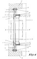
- the supporting ring 1 represented in the figures 1 to 4 is made as one monolithic piece.
- an inner part 2 at the radial inner side 3 of the supporting ring 1 an outer part 4 at the radial outer side 5 of the supporting ring 1 and an intermediate part 6 through which the outer part 4 and the inner part 2 are connected to each other.
- the inner part 2, the intermediate part 6 and the outer part 4 are all substantially ring shaped and are mounted in a concentric position.
- the inner part 2 is made in the form of a sleeve 7 which is profiled on the inner side in order to be able to receive the bearing or bearing parts to be supported by the supporting ring 1.
- the intermediate part 6 is connected to the inner part 2 and to the outer part 4, respectively by inner beams 8 and by outer beams 9.
- All these beams 8 and 9 are directed in a radial direction RR'.
- each inner beam 8 is lying diametrically with regard to an outer beam 9 and vice versa.
- the inner part 2, as well as the outer part 4, is provided with holes, respectively holes 10 and holes 11.
- holes 10 can be used for locating a bearing 14, in this case a cylindrical bearing 14, or a bearing part, like an outer bearing ring 15, in the sleeve 7 by means of a cover plate 16 which is bolted with bolts 17 to the supporting ring 1.
- the supporting ring 1 is applied in a wind turbine 18 in order to support the bearing 45 of the second planet carrier 39 of a double stage planetary gear unit connecting the rotor hub 22 of the wind turbine 18 to a generator 27.
- a typical wind turbine 18 is represented, which is composed of a nacelle 19 that is mounted rotatably on a static supporting structure 20. In this manner the wind turbine 18 can be oriented to the direction of the wind.
- a rotor 21 is mounted consisting of a rotor hub 22 to which the rotor blades 23 are fixed.
- the rotor hub 22 is connected to the input shaft 24 of a gear unit 25, while the output shaft 26 of the gear unit 25 is connected to an electrical power generator 27.
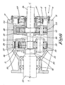
- the gear unit 25 has two planetary gear stages 28 and 29.
- the planet carrier 30 of the first planetary gear stage 28 plays the role of input shaft 24 and is connected to the rotor hub 22.
- the planet carrier 30 of the first planetary gear stage 28 is rigidly connected to the rotor hub 22, whereby the combination of rotor hub 22 and planet carrier 30 is mounted in a rotatable manner with regard to the housing 31 by means of a pair of bearings 32.
- first planetary gear stage 28 is provided with planet wheels 33 mounted rotatably by means of planet bearings 34 on planet shafts 35 which are rigidly connected to the planet carrier 30.
- These planet wheels 33 interact, on the one hand, with a ring wheel 36 that is rigidly connected to the housing 31, and, on the other hand, with a sun wheel 37 that is mounted on the output shaft 38 of the first planetary gear stage 28.
- This output shaft 38 of the first planetary gear stage 28 is in its turn used as an input shaft 38 of the second planetary gear stage 29, whereby the input shaft 38 is driving the planet carrier 39 of this second planetary gear stage 29.
- the input shaft 38 drives an output shaft 26 through the interaction of planet wheels 40 mounted on planet shafts 41 on planet carrier 39 by means of planet bearings 42, a ring wheel 43 fixedly connected to the housing 31 and a sun wheel 44 mounted on the output shaft 26.
- the planet carrier 39 of the second planetary gear stage 29 is provided with a bearing 45, which is mounted, completely in an analogous manner as in the example of figure 4 , in a supporting ring 1 in accordance with the present invention, the supporting ring 1 being connected to the housing 31.
- the intermediate part 6 of the supporting ring 1, with its inner beams 8 and outer beams 9, plays an important role.
- this intermediate part 6 is more flexible in an axial direction AA' then the inner part 2 and the outer part 4.
- Axial load on the rotor hub 22 is transmitted through the two planetary gear stages 28 and 29 to the bearing 45 and further through the supporting ring 1 to the housing 31.
- intermediate part 6 with its inner beams 8 and outer beams 9, is that it has as relatively high stiffness in a radial direction RR'.
- the supporting ring 1 is cast as one monolithic piece.
- This embodiment of the invention has the advantage that the production is very much simplified. Indeed, once the mold has been fabricated, a lot of pieces can be made very quickly, easily and less expensive.
- a supporting ring 1 is made of a ductile cast iron, also called nodular cast iron.
- Classical cast iron is rather brittle. This is caused by the high content of carbon in it. When the cast solidifies, some of this carbon precipitates as graphite flakes, the flakes enhancing the forming of cracks.
- nodulizers like magnesium or cerium
- These "nodulizers” cause the carbon to precipitate as graphite nodules rather than as flakes, so that the forming of cracks is discouraged and the metal is more ductile.
- ductile cast iron is that a stronger monolithic piece is obtained, having a good toughness and wear resistance, as well as a rather limited weight compared to its strength.
- an austempered ductile iron also known as ADI.
- An austempered ductile iron is obtained through casting as a normal ductile cast iron, whereby it is subsequently subjected to an austempering process, which ameliorates considerably its mechanical properties, like tensile strength, yield strength, fatigue strength, impact resistance, hardness, etc.
- the cast metal is first brought quickly to a temperature of about 900 to 950 °C. At this temperature a stable solid solution of iron and carbon is obtained, the so-called ⁇ -phase iron or austenite.
- the metal is then suddenly cooled (quenched) to a temperature of between 220 and 450°C, where an isothermal process is started during which residual stresses within the material are relieved and some recrystallisaton is allowed, so that the ductility increases with a minimal loss in strength.
- supporting ring 1 is made of an austempered ductile iron, with a tensile strength of minimum 1000 MPa, also known according to the Ferrocast ADI norm as F-ADI 1000 or, according to the European norm DIN EN 15 64, as EN-GJS-1000-5.
Landscapes
- Engineering & Computer Science (AREA)
- General Engineering & Computer Science (AREA)
- Mechanical Engineering (AREA)
- Life Sciences & Earth Sciences (AREA)
- Sustainable Development (AREA)
- Sustainable Energy (AREA)
- Chemical & Material Sciences (AREA)
- Combustion & Propulsion (AREA)
- Wind Motors (AREA)
- Mounting Of Bearings Or Others (AREA)
Priority Applications (5)
| Application Number | Priority Date | Filing Date | Title |
|---|---|---|---|
| EP08075022A EP2078855A1 (fr) | 2008-01-09 | 2008-01-09 | Anneau de support pour assembler un roulement ou une pièce de roulement dans une unité d'embrayage |
| CA002647631A CA2647631A1 (fr) | 2008-01-09 | 2008-12-22 | Anneau de support pour le montage d'un roulement ou de pieces de roulement dans une unite d'engrenage |
| US12/342,404 US20100002977A1 (en) | 2008-01-09 | 2008-12-23 | Supporting ring for mounting a bearing or bearing parts in a gear unit |
| AU2009200038A AU2009200038A1 (en) | 2008-01-09 | 2009-01-05 | A supporting ring for mounting a bearing or bearing parts in a gear unit |
| CNA2009100026119A CN101482148A (zh) | 2008-01-09 | 2009-01-09 | 用于在齿轮单元中安装轴承或轴承部件的支承环 |
Applications Claiming Priority (1)
| Application Number | Priority Date | Filing Date | Title |
|---|---|---|---|
| EP08075022A EP2078855A1 (fr) | 2008-01-09 | 2008-01-09 | Anneau de support pour assembler un roulement ou une pièce de roulement dans une unité d'embrayage |
Publications (1)
| Publication Number | Publication Date |
|---|---|
| EP2078855A1 true EP2078855A1 (fr) | 2009-07-15 |
Family
ID=40120437
Family Applications (1)
| Application Number | Title | Priority Date | Filing Date |
|---|---|---|---|
| EP08075022A Withdrawn EP2078855A1 (fr) | 2008-01-09 | 2008-01-09 | Anneau de support pour assembler un roulement ou une pièce de roulement dans une unité d'embrayage |
Country Status (5)
| Country | Link |
|---|---|
| US (1) | US20100002977A1 (fr) |
| EP (1) | EP2078855A1 (fr) |
| CN (1) | CN101482148A (fr) |
| AU (1) | AU2009200038A1 (fr) |
| CA (1) | CA2647631A1 (fr) |
Cited By (2)
| Publication number | Priority date | Publication date | Assignee | Title |
|---|---|---|---|---|
| US9181982B2 (en) | 2012-01-20 | 2015-11-10 | Vestas Wind Systems A/S | Blade bearing with support structure having non-uniform stiffness and method manufacture |
| EP3351830B1 (fr) | 2017-01-23 | 2019-07-31 | Flender GmbH | Engrenage planétaire comprenant un palier de porte-satellites amélioré |
Families Citing this family (2)
| Publication number | Priority date | Publication date | Assignee | Title |
|---|---|---|---|---|
| US9937509B2 (en) * | 2014-01-13 | 2018-04-10 | Silgan Dispensing Systems Corporation | Dispensing pump with skirt spring |
| JP6374765B2 (ja) * | 2014-11-12 | 2018-08-15 | 本田技研工業株式会社 | 環状バネ、並びに、それを用いたトルク検出装置及びロボット関節機構 |
Citations (6)
| Publication number | Priority date | Publication date | Assignee | Title |
|---|---|---|---|---|
| DE903762C (de) * | 1949-10-29 | 1954-02-11 | Franz Burghauser Dipl Ing | Gleit- und Waelzlager fuer stark beanspruchte Drehzapfen |
| DE934447C (de) * | 1953-04-12 | 1955-10-20 | Bayerische Motoren Werke Ag | Sicherung fuer Kugellagersitze unter Verwendung eines federnden Einbauringes |
| DE7832849U1 (de) * | 1978-11-04 | 1979-03-29 | Robert Bosch Gmbh, 7000 Stuttgart | Lagernabe für Wälzlager |
| FR2820178A1 (fr) * | 2001-02-01 | 2002-08-02 | Luk Fahrzeug Hydraulik | Dispositif de roulement |
| WO2006117515A1 (fr) * | 2005-05-05 | 2006-11-09 | Edwards Limited | Pompe a vide |
| DE102005025261A1 (de) * | 2005-06-02 | 2006-12-14 | Leybold Vacuum Gmbh | Vakuumpumpe |
Family Cites Families (22)
| Publication number | Priority date | Publication date | Assignee | Title |
|---|---|---|---|---|
| US2733108A (en) * | 1956-01-31 | Cushioned hinge bearing | ||
| US1980580A (en) * | 1933-05-13 | 1934-11-13 | Laval Separator Co De | Guide bearing for spindles of centrifuges |
| US2556317A (en) * | 1948-04-06 | 1951-06-12 | Laval Separator Co De | Bearing assembly for centrifuges and the like |
| US2762666A (en) * | 1954-06-09 | 1956-09-11 | Bendix Aviat Corp | Ball bearing retaining means |
| US3052958A (en) * | 1957-05-02 | 1962-09-11 | Thompson Ramo Wooldridge Inc | Method of making a permanent magnet rotor |
| US4248569A (en) * | 1978-11-13 | 1981-02-03 | General Motors Corporation | Stator mounting |
| IT8422055V0 (it) * | 1984-06-04 | 1984-06-04 | Roy Electrotex Spa | Alimentatore di trama per telai di tessitura comportante mezzi perfezionati per accumulare la riserva di trama. |
| US5061089A (en) * | 1990-04-16 | 1991-10-29 | Eaton Corporation | Tapered bearing isolator |
| US5044784A (en) * | 1990-07-31 | 1991-09-03 | Eaton Corporation | Bearing isolator |
| DE19632786A1 (de) * | 1996-08-15 | 1998-02-19 | Schenck Rotec Gmbh | Lagereinrichtung |
| SE517176C2 (sv) * | 1997-06-11 | 2002-04-23 | Alfa Laval Ab | Stödanordning för en centrifugalseparator |
| SE9702290D0 (sv) * | 1997-06-16 | 1997-06-16 | Alfa Laval Ab | Tätningsanordning för en centrifugalseparator |
| SE512770C2 (sv) * | 1998-02-19 | 2000-05-08 | Alfa Laval Ab | Stödanordning |
| DE29805581U1 (de) * | 1998-03-27 | 1998-05-28 | Skf Gmbh, 97421 Schweinfurt | Laufrolle |
| GB0002126D0 (en) * | 2000-01-31 | 2000-03-22 | Hanson Transmissions Internati | Planetary gear stage |
| US7679245B2 (en) * | 2001-09-17 | 2010-03-16 | Beacon Power Corporation | Repulsive lift systems, flywheel energy storage systems utilizing such systems and methods related thereto |
| US6670733B2 (en) * | 2001-09-27 | 2003-12-30 | Reliance Electric Technologies, Llc | System and method of reducing bearing voltage |
| EP1759128A1 (fr) * | 2004-06-25 | 2007-03-07 | Vestas Wind Systems A/S | Ensemble moteur a eolienne |
| EP1619400B1 (fr) * | 2004-07-20 | 2009-11-11 | VARIAN S.p.A. | Appui annulaire pour des éléments de roulement |
| US7401981B2 (en) * | 2005-07-07 | 2008-07-22 | Florida Turbine Technologies, Inc. | Bearing damper having coiled wire |
| US20070012535A1 (en) * | 2005-07-15 | 2007-01-18 | Matheny Alfred P | Laminated damper |
| BE1017135A3 (nl) * | 2006-05-11 | 2008-03-04 | Hansen Transmissions Int | Een tandwielkast voor een windturbine. |
-
2008
- 2008-01-09 EP EP08075022A patent/EP2078855A1/fr not_active Withdrawn
- 2008-12-22 CA CA002647631A patent/CA2647631A1/fr not_active Abandoned
- 2008-12-23 US US12/342,404 patent/US20100002977A1/en not_active Abandoned
-
2009
- 2009-01-05 AU AU2009200038A patent/AU2009200038A1/en not_active Abandoned
- 2009-01-09 CN CNA2009100026119A patent/CN101482148A/zh active Pending
Patent Citations (6)
| Publication number | Priority date | Publication date | Assignee | Title |
|---|---|---|---|---|
| DE903762C (de) * | 1949-10-29 | 1954-02-11 | Franz Burghauser Dipl Ing | Gleit- und Waelzlager fuer stark beanspruchte Drehzapfen |
| DE934447C (de) * | 1953-04-12 | 1955-10-20 | Bayerische Motoren Werke Ag | Sicherung fuer Kugellagersitze unter Verwendung eines federnden Einbauringes |
| DE7832849U1 (de) * | 1978-11-04 | 1979-03-29 | Robert Bosch Gmbh, 7000 Stuttgart | Lagernabe für Wälzlager |
| FR2820178A1 (fr) * | 2001-02-01 | 2002-08-02 | Luk Fahrzeug Hydraulik | Dispositif de roulement |
| WO2006117515A1 (fr) * | 2005-05-05 | 2006-11-09 | Edwards Limited | Pompe a vide |
| DE102005025261A1 (de) * | 2005-06-02 | 2006-12-14 | Leybold Vacuum Gmbh | Vakuumpumpe |
Cited By (3)
| Publication number | Priority date | Publication date | Assignee | Title |
|---|---|---|---|---|
| US9181982B2 (en) | 2012-01-20 | 2015-11-10 | Vestas Wind Systems A/S | Blade bearing with support structure having non-uniform stiffness and method manufacture |
| EP3351830B1 (fr) | 2017-01-23 | 2019-07-31 | Flender GmbH | Engrenage planétaire comprenant un palier de porte-satellites amélioré |
| EP3351830B2 (fr) † | 2017-01-23 | 2023-03-15 | Flender GmbH | Engrenage planétaire comprenant un palier de porte-satellites amélioré |
Also Published As
| Publication number | Publication date |
|---|---|
| US20100002977A1 (en) | 2010-01-07 |
| CA2647631A1 (fr) | 2009-07-09 |
| CN101482148A (zh) | 2009-07-15 |
| AU2009200038A1 (en) | 2009-07-30 |
Similar Documents
| Publication | Publication Date | Title |
|---|---|---|
| EP2072863B1 (fr) | Porte-satellites pour un étage planétaire doté d'une plaque bogie. | |
| EP2238346B1 (fr) | Étage d'engrenage épicycloïdal pour une boîte d'engrenage de turbine éolienne, boîte d'engrenage de turbine éolienne et turbine éolienne | |
| CN102287333B (zh) | 齿轮组和包括这样的齿轮组的风力涡轮机及维护方法 | |
| EP1836405B1 (fr) | Montage a roulement pour le support d'un arbre de transmission dans un logement | |
| EP2242925B1 (fr) | Chaîne dynamique pour éolienne | |
| CN101275535B (zh) | 风能设备的构件的连接结构 | |
| US8628301B2 (en) | Wind turbine rotor | |
| EP2108082B1 (fr) | Eolienne avec chaine d'entrainement | |
| US8393994B2 (en) | Gearbox for a wind turbine, a method of converting wind energy and use of a gearbox | |
| JP2003097652A (ja) | 回転入力を所定の回転出力に変換するための動力分配手段を有する歯車駆動装置 | |
| US20100009803A1 (en) | Wind power turbine and gearbox therefor | |
| EP2078855A1 (fr) | Anneau de support pour assembler un roulement ou une pièce de roulement dans une unité d'embrayage | |
| EP2215357B1 (fr) | Étage de train épicycloïdal pour boîte d'éolienne, boîte de vitesse d'éolienne et éolienne | |
| CN108661864B (zh) | 用于风轮机的齿轮箱组件的修理方法 | |
| CN101375052B (zh) | 具有完全一体的倍增器的风轮机 | |
| US5100290A (en) | Turbine generator for use in axial water flow | |
| DK2740932T3 (en) | Wind turbine | |
| US11788514B2 (en) | Wind power plant with supporting structure | |
| Raeber et al. | A new gearbox generation for vertical roller mills |
Legal Events
| Date | Code | Title | Description |
|---|---|---|---|
| PUAI | Public reference made under article 153(3) epc to a published international application that has entered the european phase |
Free format text: ORIGINAL CODE: 0009012 |
|
| AK | Designated contracting states |
Kind code of ref document: A1 Designated state(s): AT BE BG CH CY CZ DE DK EE ES FI FR GB GR HR HU IE IS IT LI LT LU LV MC MT NL NO PL PT RO SE SI SK TR |
|
| AX | Request for extension of the european patent |
Extension state: AL BA MK RS |
|
| 17P | Request for examination filed |
Effective date: 20090728 |
|
| AKX | Designation fees paid |
Designated state(s): AT BE BG CH CY CZ DE DK EE ES FI FR GB GR HR HU IE IS IT LI LT LU LV MC MT NL NO PL PT RO SE SI SK TR |
|
| STAA | Information on the status of an ep patent application or granted ep patent |
Free format text: STATUS: THE APPLICATION IS DEEMED TO BE WITHDRAWN |
|
| 18D | Application deemed to be withdrawn |
Effective date: 20110802 |