EP2078112B1 - A unit for smoothing railway rails - Google Patents
A unit for smoothing railway rails Download PDFInfo
- Publication number
- EP2078112B1 EP2078112B1 EP07805744A EP07805744A EP2078112B1 EP 2078112 B1 EP2078112 B1 EP 2078112B1 EP 07805744 A EP07805744 A EP 07805744A EP 07805744 A EP07805744 A EP 07805744A EP 2078112 B1 EP2078112 B1 EP 2078112B1
- Authority
- EP
- European Patent Office
- Prior art keywords
- unit
- sand belt
- drum
- rail
- axis
- Prior art date
- Legal status (The legal status is an assumption and is not a legal conclusion. Google has not performed a legal analysis and makes no representation as to the accuracy of the status listed.)
- Not-in-force
Links
- 238000009499 grossing Methods 0.000 title claims abstract description 25
- 239000004576 sand Substances 0.000 claims abstract description 69
- 239000000463 material Substances 0.000 claims abstract description 6
- 238000013459 approach Methods 0.000 claims description 12
- 230000009471 action Effects 0.000 claims description 6
- 238000011161 development Methods 0.000 claims description 6
- 238000004804 winding Methods 0.000 claims description 2
- 230000000295 complement effect Effects 0.000 claims 1
- 229910003460 diamond Inorganic materials 0.000 description 5
- 239000010432 diamond Substances 0.000 description 5
- 238000003754 machining Methods 0.000 description 4
- 230000009467 reduction Effects 0.000 description 4
- 238000010276 construction Methods 0.000 description 3
- 230000000694 effects Effects 0.000 description 3
- 230000010355 oscillation Effects 0.000 description 3
- 230000003746 surface roughness Effects 0.000 description 3
- 238000007667 floating Methods 0.000 description 2
- 238000012423 maintenance Methods 0.000 description 2
- 238000000034 method Methods 0.000 description 2
- 230000008569 process Effects 0.000 description 2
- 230000002441 reversible effect Effects 0.000 description 2
- 208000027418 Wounds and injury Diseases 0.000 description 1
- 238000005299 abrasion Methods 0.000 description 1
- 239000003638 chemical reducing agent Substances 0.000 description 1
- 230000006378 damage Effects 0.000 description 1
- 230000001419 dependent effect Effects 0.000 description 1
- 230000008030 elimination Effects 0.000 description 1
- 238000003379 elimination reaction Methods 0.000 description 1
- 230000036541 health Effects 0.000 description 1
- 208000014674 injury Diseases 0.000 description 1
- 238000009434 installation Methods 0.000 description 1
- 230000002452 interceptive effect Effects 0.000 description 1
- 230000001788 irregular Effects 0.000 description 1
- 238000005259 measurement Methods 0.000 description 1
- 230000000737 periodic effect Effects 0.000 description 1
- 230000002093 peripheral effect Effects 0.000 description 1
- 230000001105 regulatory effect Effects 0.000 description 1
- 238000007493 shaping process Methods 0.000 description 1
- 238000012546 transfer Methods 0.000 description 1
- 238000013519 translation Methods 0.000 description 1
- 230000001960 triggered effect Effects 0.000 description 1
Images


Classifications
-
- E—FIXED CONSTRUCTIONS
- E01—CONSTRUCTION OF ROADS, RAILWAYS, OR BRIDGES
- E01B—PERMANENT WAY; PERMANENT-WAY TOOLS; MACHINES FOR MAKING RAILWAYS OF ALL KINDS
- E01B31/00—Working rails, sleepers, baseplates, or the like, in or on the line; Machines, tools, or auxiliary devices specially designed therefor
- E01B31/02—Working rail or other metal track components on the spot
- E01B31/12—Removing metal from rails, rail joints, or baseplates, e.g. for deburring welds, reconditioning worn rails
- E01B31/17—Removing metal from rails, rail joints, or baseplates, e.g. for deburring welds, reconditioning worn rails by grinding
- E01B31/175—Removing metal from rails, rail joints, or baseplates, e.g. for deburring welds, reconditioning worn rails by grinding using grinding belts
-
- B—PERFORMING OPERATIONS; TRANSPORTING
- B24—GRINDING; POLISHING
- B24B—MACHINES, DEVICES, OR PROCESSES FOR GRINDING OR POLISHING; DRESSING OR CONDITIONING OF ABRADING SURFACES; FEEDING OF GRINDING, POLISHING, OR LAPPING AGENTS
- B24B19/00—Single-purpose machines or devices for particular grinding operations not covered by any other main group
- B24B19/004—Single-purpose machines or devices for particular grinding operations not covered by any other main group for grinding rails, T, I, H or other similar profiles
-
- B—PERFORMING OPERATIONS; TRANSPORTING
- B24—GRINDING; POLISHING
- B24B—MACHINES, DEVICES, OR PROCESSES FOR GRINDING OR POLISHING; DRESSING OR CONDITIONING OF ABRADING SURFACES; FEEDING OF GRINDING, POLISHING, OR LAPPING AGENTS
- B24B21/00—Machines or devices using grinding or polishing belts; Accessories therefor
- B24B21/004—Machines or devices using grinding or polishing belts; Accessories therefor using abrasive rolled strips
Definitions
- the present invention relates to a unit for performing mechanical smoothing operations on railway rails.
- the field of the invention is the sector of machines for the construction and maintenance of railway equipment, and it finds particular application within the domain of smoothing and shaping railway rails.
- the rail head is ground by means of appropriate grinding machines which are generally housed on railway cars or on railway vehicles specifically dedicated to restoring the geometry of the track.
- Such grinding machines are equipped with a plurality of abrasive grinding wheels, e.g. diamond disks, which are placed in contact with respective portions of the rail head to achieve a mechanical machining operation by removal of material.
- diamond disks act along a longitudinal direction with respect to the track, generally with a speed of advance given by the advance of the trolley on which the grinding machine is mounted.
- a technical task of the present invention is to propose a unit for smoothing railway rails that is free from the aforementioned problems.
- a specific object of the present invention is to propose a unit for smoothing railway rails that achieves a correct profile of the rail.
- Another object of the present invention is to propose a unit for smoothing railway rails that enables to minimise the surface roughness of the rail.
- An important object of the present invention is to make available a unit for smoothing railway rails that reduces or eliminates the risks of injury for operators assigned to use the machine itself.
- EP849397 a grinding machine which uses, as an abrasive tool, a closed abrasive belt which is driven in a continuous manner around a closed path and which has a bottom portion held in contact with the head of the rail.
- EP-A-648895 shows a unit for smoothing railway rails according to the preamble of claim 1.
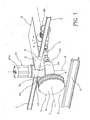
- the reference 1 indicates in its entirety a unit for smoothing railway rails.
- Said unit 1 can be stably associated to railway cars or trolleys, and it can be included in the fitting out of railway vehicles dedicated to the maintenance or to the construction of railway equipment.
- the unit according to the invention comprises a pair of support arms 2, able to be rigidly coupled to a "T" portion of a railway trolley or car, or to a portion of a railway vehicle in accordance with what has been described previously.
- the support arms 2 support, at an external end 2a thereof, an adjustment body 3 which can be made to oscillate about an axis of adjustment "X” by means of known actuators, not shown in the accompanying figures.
- the axis of adjustment "X” is positioned longitudinally to the rail "R", i.e. parallel to a prevalent direction of development of the rail "R” to be smoothed.
- the adjustment body 3 comprises an upper portion 3a and a lower portion 3b, stably fastened together at least according to rotation movements.
- the upper portion 3a and the lower portion 3b of the adjustment body 3 are mutually fastened in such a way that they cannot perform rotation movements with respect to one another.
- the support arms 2 are rotatably connected to the upper portion 3a of the adjustment body 3.
- the lower portion 3b of the adjustment body 3 rotatably supports a shaft 4 to an external end whereof is stably fastened, for example by means of threaded connections, an advancement member 5 of an abrasive element which, within the present invention, advantageously a sand belt 6.
- the advancement member 5 comprises a drum 7, which develops according to a circular profile and therefore having toroidal shape.
- the drum 7 is laterally closed by means of an outer circular plate 8 and an inner circular plate 9, parallel to each other and connected to the drum 7 by means of removable connecting elements, e.g. threaded connections.
- the inner plate 9 is directly connected, preferably in coaxial manner, to the aforesaid outer end of the shaft 4.
- the drum 7 can be obtained in a single piece with the inner plate 9, and it may be provided an outer closing plate 8 which can be fastened removable to the drum 7.
- the drum 7 is rotatable, in connection with the shaft 4 and coaxially thereto, about a respective axis of rotation "Y" preferably perpendicular to the axis of adjustment "X". Consequently, the adjustment body 3 advantageously defines means for orienting the advancement member 5 and, consequently, the sand belt 6.
- the drum 7 defines, with its own peripheral outer portion, a support surface "S" of the aforementioned sand belt 6.
- Said sand belt 6 adheres to the support surface "S", preferably under the action of a tensioning force, assuming configuration complementarily shaped to the support surface "S".
- the support medium "S” presents a concave shape according to a section view along a plane passing through the axis of rotation "Y" of the drum 7.
- the support surface "S" of the drum 7, the head rail “R” assumes, once the smoothing operation is completed, a surface shaped complementarily to a corresponding portion of the support surface "S".
- the support surface "S” has a profile, measured according to a plane passing through the axis of rotation "Y" of the drum 7, complementarily shaped with respect to a corresponding final, or theoretical, profile of the portion of rail “R” to be smoothed. This condition enables to generate a correct profile of the rail "R” with a single smoothing operation with no need to perform several passes to cover an entire development of the head of the rail "R".
- the drum 7, and in particular the guiding surface "S" defined thereby constitute means for advancing the sand belt 6 whose function is the generation of an advancing motion of the sand belt 6 relative to the rail "R”, in order to achieve of velocity of sliding of the sand belt 6 relative to the rail "R", in particular longitudinally to the rail "R” itself, and hence to generate a removal of material therefrom.
- the drum 7, in co-operation with the aforesaid pair of plates 8, 9, defines a closed manoeuvring space 10 whose function shall be illustrated below.
- the manoeuvring space 10 are housed means 11 for renewing the sand belt 6.
- the means 11 for renewing the sand belt 6 comprise a first and a second support, preferably comprising a first pivot pin 12 and a second pivot pin 13, whereon are stably supportable respectively a feeding reel 14 and a return reel 15 of the sand belt 6.
- the two pivot pins 12, 13 extend from the inner plate 9 in the direction of the outer plate 8, and they are positioned symmetrically relative to a generic diametrical segment of said plates 8, 9.
- the drum 7 also has an opening 16, at the aforementioned support surface "S", preferably having elongated shape.
- Said opening 16 has the function of putting operatively in connection the reels 14, 15 with the support surface "S”, in such a way that the reels 14, 15 in co-operation with the support surface "S” determine a path "P" of advance of the sand belt 6.
- Said sand belt 6, unwinding from the feeding reel 14 in the form of a non-worn belt 6a traverses the opening 16 and, winding the support surface "S", reaches the opening 16 again, re-traversing it and rewinding on the return reel 15 under conditions of worn belt 6b.
- the path "P" of advance of the sand belt 6 therefore is an open path.
- the opening 16 extends, along a direction perpendicular to the aforesaid plates 8, 9, for an amplitude approximating by excess the width of the sand belt 6.
- the opening 16 it is preferable for the opening 16 to have a transverse dimensions, measured along a circumferential development of the drum 7, which approximates by excess twice the thickness of the sand belt 6.
- the opening 16 can be barely traversed by a first portion of the sand belt 6 exiting the feeding reel 14 and a second portion of the sand belt 6 approaching the return reel 15 without the aforesaid two portions of the sand belt 6 interfering with each other, e.g. because of mutual rubbing.
- the reduced transverse dimension of the opening 16 maximises the portion of the support surface "S" whereon the sand belt 6 engages.
- the support surface "S” is substantially, if not at the limit totally, engaged by the sand belt 6, as shown in figure 7 .
- the drum 7 has, at the opening 16, rounded edges 17 to favour a sliding of the sand belt 6 in transit between the support surface "S" and the two reels 14, 15.
- the aforesaid two pivot pins 12, 13 are housed rotatably within respective seats, not shown in the accompanying figures, which are obtained within the inner plate 9. Moreover, at least one of the aforesaid pivot pins 12, 13, preferably both, is connected to motor means 18 which provide a motive force necessary to set in rotation of at least one of the aforementioned reels 14, 15, and in particular at least the return reel 15.
- the pivot pins 12, 13 are, additionally, preferably positioned perpendicularly relative to the inner plate 9, to rotate about respective axes parallel to the axis of rotation "Y" of the drum 7.
- the motorisation of both pivot pins 12, 13 allows a reversible operation of the unit 1, because it allows an unwinding of the sand belt 6 in both direction, i.e. it is possible to reverse the functions of the feeding reel 14 and of the return reel 15.
- the motor means 18 comprise a pair of second electric motors "M2", positioned at the housing seats of the pivot pins 12, 13 and each associated to one of the aforesaid pivot pins 12, 13.
- the second motors "M2" can be hydraulic.
- the motor means 18 are rigidly connected to the inner plate 9 on an outer surface of the plate 9, opposite relative to the aforesaid manoeuvring space 10.
- each of the two second motors "M2" is positioned to rotate about an axis that is perpendicular to the pivot pin 12, 13 whereto it is associated, and it is connected to the aforesaid respective pivot pin 12, 13 by means of a reducer 19 with orthogonal axes.
- the second motors "M2" are approached to the inner plate 9, because they extend parallel to the inner plate 9 itself, and a reduction of the total size of the unit 1 is thereby achieved.
- the drum 7 rotates about its own axis of rotation "Y" and therefore an orientation of the second motors "M2" along a radial direction of the inner plate 9 could allow a reduction of the total moment of inertia of the rotating masses, understood as an aggregate comprising the drum 7, the second motors "M2", the reels 14, 15, the plates 8, 9 and any auxiliary components.
- the presence of the motor means 18 is made necessary by the fact that the sand belt 6 engages by rubbing on the support surface "S", and in operation it is compressed between the support surface "S" and the rail "R” to be smoothed, so in order for the sand belt 6 to slide on the support surface "S” it is necessary to exert a driving force on the belt 6, which force is, in fact, provided by the motor means 18.
- the adjustment body 3 further comprises a linear actuator 20, preferably a hydraulic or pneumatic piston, which acts along a direction of approach "W” to actuate the drum 7 along said direction "W", in other words in a direction towards and/or away from the rail "R", between a non-operative position shown in figure 3 , in which the drum 7 is raised relative to the rail "R", and an operative position shown in figure 4 , in which the drum 7 abuts against the head of the rail "R", and vice versa.
- a linear actuator 20 preferably a hydraulic or pneumatic piston
- the linear actuator 20 is associated to the upper portion 3a of the adjustment body 3a, and it is active on the lower portion 3b of the adjustment body 3 to actuate the aforesaid second part 3b towards and away from the first part 3a along the aforesaid direction of approach "W". Therefore, acting directly on a portion of the adjustment body 3 able to support the shaft 4, the linear actuator 20 is able to actuate the drum 7 towards and away from the rail "R" to be smoothed. In this way, the linear actuator 20 defines means for actuating the aforesaid advancement member 5, in order to bring and maintain a portion thereof, and hence of the sand belt 6, in contact with a portion of the rail "R" to be smoothed.
- the direction of approach "W” is transverse, preferably perpendicular, with respect to the axis of adjustment "X” and, preferably, perpendicular also relative to the axis of rotation "Y" of the drum. This is obtained by mounting the linear actuator 20 in stable fashion on the upper surface 3a of the adjustment body 3, and connecting an active portion of the linear actuator 20 directly to the lower portion 3b of the adjustment body 3, in such a way that between the linear actuator 20 and the aforesaid lower portion 3b is allowed exclusively a translation movement along the aforesaid direction of approach "W".
- the linear actuator 20 comprises a cylinder 20a, rigidly coupled, for example by example by means of threaded connections, to the upper portion 3a of the adjustment body 3 at the opposite side from the lower portion 3b thereof.
- a piston not shown, operatively associated to the cylinder 20a and actuated thereby.
- the piston traverses a through seat of the upper portion 3a, which extends along the aforesaid direction of approach "W" between the cylinder 20a and the lower portion 3b of the adjustment body, and connected directly to the lower portion 3b to actuate it towards and away from the rail "R" to be smoothed.
- the advancement member 5 of the sand belt 6 is maintained raised relative to the head of the rail “R", known as “rail level”, during conditions of interruption of the operation of the unit 1 or during transfer movements thereof.
- the advancement member 5 is lowered towards the rail "R” along the aforesaid direction of approach "W", to place in contact a portion of the sand belt 6 with a portion of profile of the rail "R” to be smoothed.
- the adjustment body 3 can be made to oscillate about the aforesaid axis of adjustment "X", which is oriented parallel to a prevalent direction of development of the rail "R". Consequently, the drum 7 can be positioned on a plurality of planes, inclined differently with respect to a vertical plane, depending on the size of the oscillation imparted to the adjustment body 3 around the axis of rotation "X".
- Figures 3 and 4 show the adjustment body 3 while it is in vertical position, corresponding to a horizontal alignment of the axis of rotation "Y" of the drum 7, while figure 5 shows the adjustment body in a generic position rotated about the axis of adjustment "X”.
- the unit 1 comprises a control system, which provides for regulating the operating parameters, e.g. the speed of the sand belt 6 or the inclination of the drum 7 about the axis of adjustment "X”, by actuating respective command members.
- the control system acts on the second motors "M2", on the linear actuator 20 and on the actuators provided for the oscillation of the adjustment body 3, as well as on the first motor "M1".
- control system preferably takes in place in co-operation with operations for measuring parameters such as the presence of long and/or short undulations and roughness in the longitudinal profile of the rail, to determine operating parameters such as the thickness of material to be removed from the head of the rail "R" the speed of advance of the railway vehicle or the speed of advance of the sand belt 6.
- Said measurements are performed by a diagnostic apparatus, which is connected to the aforesaid control system and can also comprise cameras applied to the railway car or vehicle to monitor one or more diagnostic parameters.
- the unit 1 according to the invention can be provided, fitted on railway cars or vehicles, coupled to one or more other units identical thereto.
- Said railway car or vehicle therefore comprises two or more units 1, each of which having the characteristics listed in the previous detailed description.
- the unit 1 is able to work on a respective rail "R" of the track, and it is associated to a floating support common to at least two of the aforesaid units 1 for smoothing the rail "R".
- Said floating support is self-aligning, i.e. it is balanced gravitationally in such a way as to be constantly positioned on a horizontal plane. In this way, the simultaneous smoothing of the two rails "R" of the track allows to eliminate flaws of surface irregularity or wear of the head of the rail "R” which alter its profile relative to a theoretical, optimal one.
- the present invention achieves the proposed objects, overcoming the drawbacks of the prior art.
- a sand belt coupled to a drum having a surface for supporting the sand belt that is shaped complementarily to the head of the rail enables to perform smoothing operations on the entire surface of the head of the rail, eliminating problems of the emergence of polygonising effects on the final surface of the rail.
- a sand belt instead of an abrasive disk, as is instead adopted in the prior art, allows to eliminate the risks of sudden breakage, typical of abrasive disks, with the consequent elimination of health and safety hazards for any operators acting in proximity to the sand belt.
- the present invention also achieves other important advantages.
- the presence of the drum for the definition of the support surface of the sand belt enables to carry out smoothing operations on the rail even at low speeds of the railway car or vehicle supporting the smoothing unit, because it is sufficient to adjust the speed of rotation of the drum the adjust the removal of material in the smoothing phase.
- the presence of the feed and return reels enables to provide an advancing motion of the sand belt relative to the drum, in order to provide for a gradual renewal of the sand belt, which is progressively unwound from the feeding reel in the form of a non-worn belt, whilst the born belt is wound on the return reel.
- the support of the reels and of the second motors on the drum and integrally therewith enables to maintain a low speed of the sand belt relative to the drum, linked to the action of renewal of the belt itself, whilst maintaining a sufficient relative speed between belt and rail thanks to the rotation of the drum. Therefore, the quantity of sand belt required is maintained at low levels, and high dissipation of energy is avoided thanks to the aforementioned possibility of keeping low the speed of sliding of the belt relative the drum, linked to the speed of renewal of the belt.
Landscapes
- Engineering & Computer Science (AREA)
- Mechanical Engineering (AREA)
- Architecture (AREA)
- Civil Engineering (AREA)
- Structural Engineering (AREA)
- Machines For Laying And Maintaining Railways (AREA)
- Coating Apparatus (AREA)
Applications Claiming Priority (2)
| Application Number | Priority Date | Filing Date | Title |
|---|---|---|---|
| ITRM20060588 ITRM20060588A1 (it) | 2006-10-30 | 2006-10-30 | Unita per la levigatura di rotaie ferroviarie |
| PCT/IT2007/000533 WO2008053505A1 (en) | 2006-10-30 | 2007-07-27 | A unit for smoothing railway rails |
Publications (2)
| Publication Number | Publication Date |
|---|---|
| EP2078112A1 EP2078112A1 (en) | 2009-07-15 |
| EP2078112B1 true EP2078112B1 (en) | 2012-06-06 |
Family
ID=38666939
Family Applications (1)
| Application Number | Title | Priority Date | Filing Date |
|---|---|---|---|
| EP07805744A Not-in-force EP2078112B1 (en) | 2006-10-30 | 2007-07-27 | A unit for smoothing railway rails |
Country Status (3)
| Country | Link |
|---|---|
| EP (1) | EP2078112B1 (it) |
| IT (1) | ITRM20060588A1 (it) |
| WO (1) | WO2008053505A1 (it) |
Families Citing this family (1)
| Publication number | Priority date | Publication date | Assignee | Title |
|---|---|---|---|---|
| CN112853837A (zh) * | 2021-04-12 | 2021-05-28 | 华夏高铁技术有限公司 | 一种多功能钢轨砂带打磨机 |
Citations (1)
| Publication number | Priority date | Publication date | Assignee | Title |
|---|---|---|---|---|
| EP0648895A2 (de) * | 1993-10-18 | 1995-04-19 | Franz Plasser Bahnbaumaschinen-Industriegesellschaft m.b.H. | Schienenschleifmaschine |
Family Cites Families (3)
| Publication number | Priority date | Publication date | Assignee | Title |
|---|---|---|---|---|
| DE3243602A1 (de) * | 1982-11-25 | 1984-05-30 | Elektro-Thermit Gmbh, 4300 Essen | Auf einer oder beiden schiene(n) eines gleises verfahrbare schienenschleifmaschine |
| CH690963A5 (fr) | 1996-12-20 | 2001-03-15 | Speno Internat S A | Dispositif pour la finition du reprofilage en voie et en continu de la surface du champignon d'au moins un rail d'une voie ferrée. |
| FR2764224B1 (fr) * | 1997-06-06 | 1999-08-27 | Procede Machines Speciales Spm | Machine d'usinage par bande abrasive de portees cylindriques d'arbres |
-
2006
- 2006-10-30 IT ITRM20060588 patent/ITRM20060588A1/it unknown
-
2007
- 2007-07-27 WO PCT/IT2007/000533 patent/WO2008053505A1/en not_active Ceased
- 2007-07-27 EP EP07805744A patent/EP2078112B1/en not_active Not-in-force
Patent Citations (1)
| Publication number | Priority date | Publication date | Assignee | Title |
|---|---|---|---|---|
| EP0648895A2 (de) * | 1993-10-18 | 1995-04-19 | Franz Plasser Bahnbaumaschinen-Industriegesellschaft m.b.H. | Schienenschleifmaschine |
Also Published As
| Publication number | Publication date |
|---|---|
| WO2008053505A1 (en) | 2008-05-08 |
| EP2078112A1 (en) | 2009-07-15 |
| ITRM20060588A1 (it) | 2008-04-30 |
Similar Documents
| Publication | Publication Date | Title |
|---|---|---|
| CA1167647A (en) | Grinding device for the reprofiling of a rail of a railway track | |
| JP2017522468A (ja) | 接線研削機械 | |
| CA2141511C (en) | Rail grinding machine for grinding rails of a track | |
| US4920701A (en) | Device for the reprofiling of the rails of a railway track | |
| US7845098B1 (en) | Rotary undercutter for rail line maintenance | |
| SK125894A3 (en) | Rail grinding machine | |
| CN107938445B (zh) | 自行式钢轨打磨车 | |
| PL120775B1 (en) | Self-propelled railroad machine for removing by machining the defects and deformations on rail head top surface in particular furrows thereon and method of removing such defects and deformationsormacijj verkhnejj poverkhnosti golovki rel'sov,a osobenno ikh uglublenijj i sposob ustranenija putem obrabotki ubytkov deformacijj poverkhnosti rel'sov | |
| CN108166341B (zh) | 一种轨廓轨迹数控精磨机 | |
| CN110977702A (zh) | 一种柔性打磨的轨道焊缝打磨机器人 | |
| US10974358B2 (en) | System for reprofiling a wheel set of a railway vehicle | |
| KR101373803B1 (ko) | 레일의 이물질 제거장치 | |
| CN113136751A (zh) | 一种钢轨复合打磨车 | |
| EP2078112B1 (en) | A unit for smoothing railway rails | |
| KR101194791B1 (ko) | 분기기 레일연마기 | |
| CN113174790A (zh) | 一种钢轨复合打磨方法 | |
| US5293718A (en) | Tangential grinding machine particularly for railway rails | |
| CN113026454A (zh) | 一种钢轨复合打磨装置 | |
| US6981907B1 (en) | High angle grinder | |
| JP2014105443A (ja) | レール削正車両 | |
| CN111851176A (zh) | 钢轨仿形打磨机 | |
| CN118516883A (zh) | 一种走行装置、钢轨整修设备及道岔通过方法 | |
| RU2759298C1 (ru) | Способ обработки поверхности головки рельса и устройство для его осуществления | |
| CN220806744U (zh) | 一种门架式模板自动打磨装置 | |
| GB2110176A (en) | Brush assembly for vehicle washing apparatus |
Legal Events
| Date | Code | Title | Description |
|---|---|---|---|
| PUAI | Public reference made under article 153(3) epc to a published international application that has entered the european phase |
Free format text: ORIGINAL CODE: 0009012 |
|
| 17P | Request for examination filed |
Effective date: 20090416 |
|
| AK | Designated contracting states |
Kind code of ref document: A1 Designated state(s): AT BE BG CH CY CZ DE DK EE ES FI FR GB GR HU IE IS IT LI LT LU LV MC MT NL PL PT RO SE SI SK TR |
|
| 17Q | First examination report despatched |
Effective date: 20100518 |
|
| REG | Reference to a national code |
Ref country code: DE Ref legal event code: R079 Ref document number: 602007023194 Country of ref document: DE Free format text: PREVIOUS MAIN CLASS: E01B0031170000 Ipc: B24B0019000000 |
|
| GRAP | Despatch of communication of intention to grant a patent |
Free format text: ORIGINAL CODE: EPIDOSNIGR1 |
|
| RIC1 | Information provided on ipc code assigned before grant |
Ipc: E01B 31/17 20060101ALI20111128BHEP Ipc: B24B 21/00 20060101ALI20111128BHEP Ipc: B24B 19/00 20060101AFI20111128BHEP |
|
| DAX | Request for extension of the european patent (deleted) | ||
| GRAS | Grant fee paid |
Free format text: ORIGINAL CODE: EPIDOSNIGR3 |
|
| GRAA | (expected) grant |
Free format text: ORIGINAL CODE: 0009210 |
|
| AK | Designated contracting states |
Kind code of ref document: B1 Designated state(s): AT BE BG CH CY CZ DE DK EE ES FI FR GB GR HU IE IS IT LI LT LU LV MC MT NL PL PT RO SE SI SK TR |
|
| REG | Reference to a national code |
Ref country code: GB Ref legal event code: FG4D |
|
| REG | Reference to a national code |
Ref country code: AT Ref legal event code: REF Ref document number: 560777 Country of ref document: AT Kind code of ref document: T Effective date: 20120615 Ref country code: CH Ref legal event code: EP |
|
| REG | Reference to a national code |
Ref country code: IE Ref legal event code: FG4D |
|
| REG | Reference to a national code |
Ref country code: DE Ref legal event code: R096 Ref document number: 602007023194 Country of ref document: DE Effective date: 20120802 |
|
| REG | Reference to a national code |
Ref country code: NL Ref legal event code: VDEP Effective date: 20120606 |
|
| PG25 | Lapsed in a contracting state [announced via postgrant information from national office to epo] |
Ref country code: FI Free format text: LAPSE BECAUSE OF FAILURE TO SUBMIT A TRANSLATION OF THE DESCRIPTION OR TO PAY THE FEE WITHIN THE PRESCRIBED TIME-LIMIT Effective date: 20120606 Ref country code: CY Free format text: LAPSE BECAUSE OF FAILURE TO SUBMIT A TRANSLATION OF THE DESCRIPTION OR TO PAY THE FEE WITHIN THE PRESCRIBED TIME-LIMIT Effective date: 20120606 Ref country code: SE Free format text: LAPSE BECAUSE OF FAILURE TO SUBMIT A TRANSLATION OF THE DESCRIPTION OR TO PAY THE FEE WITHIN THE PRESCRIBED TIME-LIMIT Effective date: 20120606 Ref country code: LT Free format text: LAPSE BECAUSE OF FAILURE TO SUBMIT A TRANSLATION OF THE DESCRIPTION OR TO PAY THE FEE WITHIN THE PRESCRIBED TIME-LIMIT Effective date: 20120606 |
|
| REG | Reference to a national code |
Ref country code: AT Ref legal event code: MK05 Ref document number: 560777 Country of ref document: AT Kind code of ref document: T Effective date: 20120606 |
|
| REG | Reference to a national code |
Ref country code: LT Ref legal event code: MG4D Effective date: 20120606 |
|
| PG25 | Lapsed in a contracting state [announced via postgrant information from national office to epo] |
Ref country code: SI Free format text: LAPSE BECAUSE OF FAILURE TO SUBMIT A TRANSLATION OF THE DESCRIPTION OR TO PAY THE FEE WITHIN THE PRESCRIBED TIME-LIMIT Effective date: 20120606 Ref country code: GR Free format text: LAPSE BECAUSE OF FAILURE TO SUBMIT A TRANSLATION OF THE DESCRIPTION OR TO PAY THE FEE WITHIN THE PRESCRIBED TIME-LIMIT Effective date: 20120907 Ref country code: LV Free format text: LAPSE BECAUSE OF FAILURE TO SUBMIT A TRANSLATION OF THE DESCRIPTION OR TO PAY THE FEE WITHIN THE PRESCRIBED TIME-LIMIT Effective date: 20120606 |
|
| PG25 | Lapsed in a contracting state [announced via postgrant information from national office to epo] |
Ref country code: BE Free format text: LAPSE BECAUSE OF FAILURE TO SUBMIT A TRANSLATION OF THE DESCRIPTION OR TO PAY THE FEE WITHIN THE PRESCRIBED TIME-LIMIT Effective date: 20120606 Ref country code: RO Free format text: LAPSE BECAUSE OF FAILURE TO SUBMIT A TRANSLATION OF THE DESCRIPTION OR TO PAY THE FEE WITHIN THE PRESCRIBED TIME-LIMIT Effective date: 20120606 Ref country code: CZ Free format text: LAPSE BECAUSE OF FAILURE TO SUBMIT A TRANSLATION OF THE DESCRIPTION OR TO PAY THE FEE WITHIN THE PRESCRIBED TIME-LIMIT Effective date: 20120606 Ref country code: SK Free format text: LAPSE BECAUSE OF FAILURE TO SUBMIT A TRANSLATION OF THE DESCRIPTION OR TO PAY THE FEE WITHIN THE PRESCRIBED TIME-LIMIT Effective date: 20120606 Ref country code: AT Free format text: LAPSE BECAUSE OF FAILURE TO SUBMIT A TRANSLATION OF THE DESCRIPTION OR TO PAY THE FEE WITHIN THE PRESCRIBED TIME-LIMIT Effective date: 20120606 Ref country code: EE Free format text: LAPSE BECAUSE OF FAILURE TO SUBMIT A TRANSLATION OF THE DESCRIPTION OR TO PAY THE FEE WITHIN THE PRESCRIBED TIME-LIMIT Effective date: 20120606 Ref country code: NL Free format text: LAPSE BECAUSE OF FAILURE TO SUBMIT A TRANSLATION OF THE DESCRIPTION OR TO PAY THE FEE WITHIN THE PRESCRIBED TIME-LIMIT Effective date: 20120606 Ref country code: IS Free format text: LAPSE BECAUSE OF FAILURE TO SUBMIT A TRANSLATION OF THE DESCRIPTION OR TO PAY THE FEE WITHIN THE PRESCRIBED TIME-LIMIT Effective date: 20121006 |
|
| PG25 | Lapsed in a contracting state [announced via postgrant information from national office to epo] |
Ref country code: MC Free format text: LAPSE BECAUSE OF NON-PAYMENT OF DUE FEES Effective date: 20120731 Ref country code: PT Free format text: LAPSE BECAUSE OF FAILURE TO SUBMIT A TRANSLATION OF THE DESCRIPTION OR TO PAY THE FEE WITHIN THE PRESCRIBED TIME-LIMIT Effective date: 20121008 Ref country code: PL Free format text: LAPSE BECAUSE OF FAILURE TO SUBMIT A TRANSLATION OF THE DESCRIPTION OR TO PAY THE FEE WITHIN THE PRESCRIBED TIME-LIMIT Effective date: 20120606 Ref country code: IT Free format text: LAPSE BECAUSE OF FAILURE TO SUBMIT A TRANSLATION OF THE DESCRIPTION OR TO PAY THE FEE WITHIN THE PRESCRIBED TIME-LIMIT Effective date: 20120606 |
|
| REG | Reference to a national code |
Ref country code: CH Ref legal event code: PL |
|
| PLBE | No opposition filed within time limit |
Free format text: ORIGINAL CODE: 0009261 |
|
| STAA | Information on the status of an ep patent application or granted ep patent |
Free format text: STATUS: NO OPPOSITION FILED WITHIN TIME LIMIT |
|
| PG25 | Lapsed in a contracting state [announced via postgrant information from national office to epo] |
Ref country code: CH Free format text: LAPSE BECAUSE OF NON-PAYMENT OF DUE FEES Effective date: 20120731 Ref country code: LI Free format text: LAPSE BECAUSE OF NON-PAYMENT OF DUE FEES Effective date: 20120731 Ref country code: DK Free format text: LAPSE BECAUSE OF FAILURE TO SUBMIT A TRANSLATION OF THE DESCRIPTION OR TO PAY THE FEE WITHIN THE PRESCRIBED TIME-LIMIT Effective date: 20120606 Ref country code: ES Free format text: LAPSE BECAUSE OF FAILURE TO SUBMIT A TRANSLATION OF THE DESCRIPTION OR TO PAY THE FEE WITHIN THE PRESCRIBED TIME-LIMIT Effective date: 20120917 |
|
| REG | Reference to a national code |
Ref country code: IE Ref legal event code: MM4A |
|
| 26N | No opposition filed |
Effective date: 20130307 |
|
| REG | Reference to a national code |
Ref country code: DE Ref legal event code: R097 Ref document number: 602007023194 Country of ref document: DE Effective date: 20130307 |
|
| PG25 | Lapsed in a contracting state [announced via postgrant information from national office to epo] |
Ref country code: MT Free format text: LAPSE BECAUSE OF FAILURE TO SUBMIT A TRANSLATION OF THE DESCRIPTION OR TO PAY THE FEE WITHIN THE PRESCRIBED TIME-LIMIT Effective date: 20120606 Ref country code: BG Free format text: LAPSE BECAUSE OF FAILURE TO SUBMIT A TRANSLATION OF THE DESCRIPTION OR TO PAY THE FEE WITHIN THE PRESCRIBED TIME-LIMIT Effective date: 20120906 Ref country code: IE Free format text: LAPSE BECAUSE OF NON-PAYMENT OF DUE FEES Effective date: 20120727 |
|
| PG25 | Lapsed in a contracting state [announced via postgrant information from national office to epo] |
Ref country code: TR Free format text: LAPSE BECAUSE OF FAILURE TO SUBMIT A TRANSLATION OF THE DESCRIPTION OR TO PAY THE FEE WITHIN THE PRESCRIBED TIME-LIMIT Effective date: 20120606 |
|
| PG25 | Lapsed in a contracting state [announced via postgrant information from national office to epo] |
Ref country code: LU Free format text: LAPSE BECAUSE OF NON-PAYMENT OF DUE FEES Effective date: 20120727 |
|
| PG25 | Lapsed in a contracting state [announced via postgrant information from national office to epo] |
Ref country code: HU Free format text: LAPSE BECAUSE OF FAILURE TO SUBMIT A TRANSLATION OF THE DESCRIPTION OR TO PAY THE FEE WITHIN THE PRESCRIBED TIME-LIMIT Effective date: 20070727 |
|
| PGFP | Annual fee paid to national office [announced via postgrant information from national office to epo] |
Ref country code: FR Payment date: 20140731 Year of fee payment: 8 Ref country code: GB Payment date: 20140729 Year of fee payment: 8 |
|
| PGFP | Annual fee paid to national office [announced via postgrant information from national office to epo] |
Ref country code: DE Payment date: 20140930 Year of fee payment: 8 |
|
| REG | Reference to a national code |
Ref country code: DE Ref legal event code: R119 Ref document number: 602007023194 Country of ref document: DE |
|
| GBPC | Gb: european patent ceased through non-payment of renewal fee |
Effective date: 20150727 |
|
| PG25 | Lapsed in a contracting state [announced via postgrant information from national office to epo] |
Ref country code: DE Free format text: LAPSE BECAUSE OF NON-PAYMENT OF DUE FEES Effective date: 20160202 Ref country code: GB Free format text: LAPSE BECAUSE OF NON-PAYMENT OF DUE FEES Effective date: 20150727 |
|
| REG | Reference to a national code |
Ref country code: FR Ref legal event code: ST Effective date: 20160331 |
|
| PG25 | Lapsed in a contracting state [announced via postgrant information from national office to epo] |
Ref country code: FR Free format text: LAPSE BECAUSE OF NON-PAYMENT OF DUE FEES Effective date: 20150731 |