EP2077458A1 - White polyester film for light reflective plate - Google Patents
White polyester film for light reflective plate Download PDFInfo
- Publication number
- EP2077458A1 EP2077458A1 EP07830316A EP07830316A EP2077458A1 EP 2077458 A1 EP2077458 A1 EP 2077458A1 EP 07830316 A EP07830316 A EP 07830316A EP 07830316 A EP07830316 A EP 07830316A EP 2077458 A1 EP2077458 A1 EP 2077458A1
- Authority
- EP
- European Patent Office
- Prior art keywords
- layer
- light
- film
- polyester film
- reflective plate
- Prior art date
- Legal status (The legal status is an assumption and is not a legal conclusion. Google has not performed a legal analysis and makes no representation as to the accuracy of the status listed.)
- Ceased
Links
- 229920006267 polyester film Polymers 0.000 title claims abstract description 66
- 239000004973 liquid crystal related substance Substances 0.000 claims abstract description 83
- 238000000034 method Methods 0.000 claims abstract description 63
- 230000003595 spectral effect Effects 0.000 claims abstract description 12
- 239000002245 particle Substances 0.000 claims description 124
- 239000012798 spherical particle Substances 0.000 claims description 104
- 229920005989 resin Polymers 0.000 claims description 77
- 239000011347 resin Substances 0.000 claims description 77
- 239000011230 binding agent Substances 0.000 claims description 37
- 239000004611 light stabiliser Substances 0.000 claims description 32
- 239000006097 ultraviolet radiation absorber Substances 0.000 claims description 32
- 229920000728 polyester Polymers 0.000 claims description 31
- 239000000178 monomer Substances 0.000 claims description 25
- 229920001577 copolymer Polymers 0.000 claims description 19
- 229920006243 acrylic copolymer Polymers 0.000 claims description 17
- 229920002554 vinyl polymer Polymers 0.000 claims description 15
- 239000010954 inorganic particle Substances 0.000 claims description 14
- 239000011146 organic particle Substances 0.000 claims description 14
- 239000006096 absorbing agent Substances 0.000 claims description 12
- PPBRXRYQALVLMV-UHFFFAOYSA-N Styrene Natural products C=CC1=CC=CC=C1 PPBRXRYQALVLMV-UHFFFAOYSA-N 0.000 claims description 11
- 239000012964 benzotriazole Substances 0.000 claims description 10
- QRUDEWIWKLJBPS-UHFFFAOYSA-N benzotriazole Chemical compound C1=CC=C2N[N][N]C2=C1 QRUDEWIWKLJBPS-UHFFFAOYSA-N 0.000 claims description 9
- 239000004925 Acrylic resin Substances 0.000 claims description 8
- 239000004793 Polystyrene Substances 0.000 claims description 8
- 150000001412 amines Chemical class 0.000 claims description 8
- 229920002223 polystyrene Polymers 0.000 claims description 8
- 229920000178 Acrylic resin Polymers 0.000 claims description 7
- RWCCWEUUXYIKHB-UHFFFAOYSA-N benzophenone Chemical compound C=1C=CC=CC=1C(=O)C1=CC=CC=C1 RWCCWEUUXYIKHB-UHFFFAOYSA-N 0.000 claims description 7
- 239000012965 benzophenone Substances 0.000 claims description 7
- 238000004132 cross linking Methods 0.000 claims description 7
- VVQNEPGJFQJSBK-UHFFFAOYSA-N Methyl methacrylate Chemical compound COC(=O)C(C)=C VVQNEPGJFQJSBK-UHFFFAOYSA-N 0.000 claims description 4
- 229920005990 polystyrene resin Polymers 0.000 claims description 4
- JYEUMXHLPRZUAT-UHFFFAOYSA-N 1,2,3-triazine Chemical compound C1=CN=NN=C1 JYEUMXHLPRZUAT-UHFFFAOYSA-N 0.000 claims description 3
- PQJZHMCWDKOPQG-UHFFFAOYSA-N 2-anilino-2-oxoacetic acid Chemical compound OC(=O)C(=O)NC1=CC=CC=C1 PQJZHMCWDKOPQG-UHFFFAOYSA-N 0.000 claims description 3
- DBCAQXHNJOFNGC-UHFFFAOYSA-N 4-bromo-1,1,1-trifluorobutane Chemical compound FC(F)(F)CCCBr DBCAQXHNJOFNGC-UHFFFAOYSA-N 0.000 claims description 3
- 229920001651 Cyanoacrylate Polymers 0.000 claims description 3
- MWCLLHOVUTZFKS-UHFFFAOYSA-N Methyl cyanoacrylate Chemical compound COC(=O)C(=C)C#N MWCLLHOVUTZFKS-UHFFFAOYSA-N 0.000 claims description 3
- STVZJERGLQHEKB-UHFFFAOYSA-N ethylene glycol dimethacrylate Substances CC(=C)C(=O)OCCOC(=O)C(C)=C STVZJERGLQHEKB-UHFFFAOYSA-N 0.000 claims description 3
- 229920002050 silicone resin Polymers 0.000 claims description 3
- 239000010410 layer Substances 0.000 description 174
- 239000011248 coating agent Substances 0.000 description 42
- 238000000576 coating method Methods 0.000 description 42
- 230000000052 comparative effect Effects 0.000 description 40
- 239000000243 solution Substances 0.000 description 36
- -1 polymethylene terephthalate Polymers 0.000 description 34
- NIXOWILDQLNWCW-UHFFFAOYSA-N acrylic acid group Chemical group C(C=C)(=O)O NIXOWILDQLNWCW-UHFFFAOYSA-N 0.000 description 33
- 229920000642 polymer Polymers 0.000 description 31
- 239000000203 mixture Substances 0.000 description 28
- VYPSYNLAJGMNEJ-UHFFFAOYSA-N Silicium dioxide Chemical compound O=[Si]=O VYPSYNLAJGMNEJ-UHFFFAOYSA-N 0.000 description 23
- 230000000694 effects Effects 0.000 description 23
- 239000000758 substrate Substances 0.000 description 21
- 239000000463 material Substances 0.000 description 19
- XLOMVQKBTHCTTD-UHFFFAOYSA-N Zinc monoxide Chemical compound [Zn]=O XLOMVQKBTHCTTD-UHFFFAOYSA-N 0.000 description 16
- 229920000139 polyethylene terephthalate Polymers 0.000 description 14
- 239000005020 polyethylene terephthalate Substances 0.000 description 14
- 239000006185 dispersion Substances 0.000 description 13
- XEKOWRVHYACXOJ-UHFFFAOYSA-N Ethyl acetate Chemical compound CCOC(C)=O XEKOWRVHYACXOJ-UHFFFAOYSA-N 0.000 description 12
- 125000000391 vinyl group Chemical group [H]C([*])=C([H])[H] 0.000 description 12
- LYCAIKOWRPUZTN-UHFFFAOYSA-N Ethylene glycol Chemical compound OCCO LYCAIKOWRPUZTN-UHFFFAOYSA-N 0.000 description 11
- 230000001965 increasing effect Effects 0.000 description 11
- 150000001875 compounds Chemical class 0.000 description 10
- 238000009792 diffusion process Methods 0.000 description 10
- 230000005484 gravity Effects 0.000 description 10
- 230000006872 improvement Effects 0.000 description 10
- 239000007788 liquid Substances 0.000 description 10
- 229920003023 plastic Polymers 0.000 description 9
- 239000000377 silicon dioxide Substances 0.000 description 9
- 238000004383 yellowing Methods 0.000 description 9
- 239000003054 catalyst Substances 0.000 description 8
- 238000011156 evaluation Methods 0.000 description 8
- 238000005259 measurement Methods 0.000 description 8
- 239000003960 organic solvent Substances 0.000 description 8
- 238000012360 testing method Methods 0.000 description 8
- 239000011787 zinc oxide Substances 0.000 description 8
- 230000008859 change Effects 0.000 description 7
- 229920001223 polyethylene glycol Polymers 0.000 description 7
- 239000011148 porous material Substances 0.000 description 7
- 239000000126 substance Substances 0.000 description 7
- 239000011800 void material Substances 0.000 description 7
- 239000002202 Polyethylene glycol Substances 0.000 description 6
- QQVIHTHCMHWDBS-UHFFFAOYSA-N isophthalic acid Chemical compound OC(=O)C1=CC=CC(C(O)=O)=C1 QQVIHTHCMHWDBS-UHFFFAOYSA-N 0.000 description 6
- 229910052751 metal Inorganic materials 0.000 description 6
- 239000002184 metal Substances 0.000 description 6
- 150000002894 organic compounds Chemical class 0.000 description 6
- 238000003756 stirring Methods 0.000 description 6
- 230000003247 decreasing effect Effects 0.000 description 5
- 230000003287 optical effect Effects 0.000 description 5
- 229920001296 polysiloxane Polymers 0.000 description 5
- KKEYFWRCBNTPAC-UHFFFAOYSA-N Terephthalic acid Chemical compound OC(=O)C1=CC=C(C(O)=O)C=C1 KKEYFWRCBNTPAC-UHFFFAOYSA-N 0.000 description 4
- GWEVSGVZZGPLCZ-UHFFFAOYSA-N Titan oxide Chemical compound O=[Ti]=O GWEVSGVZZGPLCZ-UHFFFAOYSA-N 0.000 description 4
- 239000000654 additive Substances 0.000 description 4
- WNLRTRBMVRJNCN-UHFFFAOYSA-N adipic acid Chemical compound OC(=O)CCCCC(O)=O WNLRTRBMVRJNCN-UHFFFAOYSA-N 0.000 description 4
- 229910000420 cerium oxide Inorganic materials 0.000 description 4
- 239000011521 glass Substances 0.000 description 4
- WGCNASOHLSPBMP-UHFFFAOYSA-N hydroxyacetaldehyde Natural products OCC=O WGCNASOHLSPBMP-UHFFFAOYSA-N 0.000 description 4
- BMMGVYCKOGBVEV-UHFFFAOYSA-N oxo(oxoceriooxy)cerium Chemical compound [Ce]=O.O=[Ce]=O BMMGVYCKOGBVEV-UHFFFAOYSA-N 0.000 description 4
- XNGIFLGASWRNHJ-UHFFFAOYSA-N phthalic acid Chemical compound OC(=O)C1=CC=CC=C1C(O)=O XNGIFLGASWRNHJ-UHFFFAOYSA-N 0.000 description 4
- 229920006122 polyamide resin Polymers 0.000 description 4
- 229920001707 polybutylene terephthalate Polymers 0.000 description 4
- 238000006116 polymerization reaction Methods 0.000 description 4
- 229920000306 polymethylpentene Polymers 0.000 description 4
- 239000011116 polymethylpentene Substances 0.000 description 4
- CXMXRPHRNRROMY-UHFFFAOYSA-N sebacic acid Chemical compound OC(=O)CCCCCCCCC(O)=O CXMXRPHRNRROMY-UHFFFAOYSA-N 0.000 description 4
- 229910052814 silicon oxide Inorganic materials 0.000 description 4
- 230000003746 surface roughness Effects 0.000 description 4
- OGIDPMRJRNCKJF-UHFFFAOYSA-N titanium oxide Inorganic materials [Ti]=O OGIDPMRJRNCKJF-UHFFFAOYSA-N 0.000 description 4
- YXFVVABEGXRONW-UHFFFAOYSA-N Toluene Chemical compound CC1=CC=CC=C1 YXFVVABEGXRONW-UHFFFAOYSA-N 0.000 description 3
- 229910052787 antimony Inorganic materials 0.000 description 3
- 238000000149 argon plasma sintering Methods 0.000 description 3
- 238000006243 chemical reaction Methods 0.000 description 3
- 238000007334 copolymerization reaction Methods 0.000 description 3
- 238000001514 detection method Methods 0.000 description 3
- MTHSVFCYNBDYFN-UHFFFAOYSA-N diethylene glycol Chemical compound OCCOCCO MTHSVFCYNBDYFN-UHFFFAOYSA-N 0.000 description 3
- 150000002009 diols Chemical class 0.000 description 3
- 229910052744 lithium Inorganic materials 0.000 description 3
- 229910052749 magnesium Inorganic materials 0.000 description 3
- 239000011777 magnesium Substances 0.000 description 3
- 238000004519 manufacturing process Methods 0.000 description 3
- 238000002844 melting Methods 0.000 description 3
- 229910052698 phosphorus Inorganic materials 0.000 description 3
- 229920001515 polyalkylene glycol Polymers 0.000 description 3
- 229920000098 polyolefin Polymers 0.000 description 3
- 229910052700 potassium Inorganic materials 0.000 description 3
- 150000003254 radicals Chemical class 0.000 description 3
- 235000012239 silicon dioxide Nutrition 0.000 description 3
- 239000002344 surface layer Substances 0.000 description 3
- 229910052719 titanium Inorganic materials 0.000 description 3
- 239000010936 titanium Substances 0.000 description 3
- XLYOFNOQVPJJNP-UHFFFAOYSA-N water Substances O XLYOFNOQVPJJNP-UHFFFAOYSA-N 0.000 description 3
- VBICKXHEKHSIBG-UHFFFAOYSA-N 1-monostearoylglycerol Chemical compound CCCCCCCCCCCCCCCCCC(=O)OCC(O)CO VBICKXHEKHSIBG-UHFFFAOYSA-N 0.000 description 2
- VCYCUECVHJJFIQ-UHFFFAOYSA-N 2-[3-(benzotriazol-2-yl)-4-hydroxyphenyl]ethyl 2-methylprop-2-enoate Chemical class CC(=C)C(=O)OCCC1=CC=C(O)C(N2N=C3C=CC=CC3=N2)=C1 VCYCUECVHJJFIQ-UHFFFAOYSA-N 0.000 description 2
- VTYYLEPIZMXCLO-UHFFFAOYSA-L Calcium carbonate Chemical compound [Ca+2].[O-]C([O-])=O VTYYLEPIZMXCLO-UHFFFAOYSA-L 0.000 description 2
- OFOBLEOULBTSOW-UHFFFAOYSA-N Malonic acid Chemical compound OC(=O)CC(O)=O OFOBLEOULBTSOW-UHFFFAOYSA-N 0.000 description 2
- GRYLNZFGIOXLOG-UHFFFAOYSA-N Nitric acid Chemical compound O[N+]([O-])=O GRYLNZFGIOXLOG-UHFFFAOYSA-N 0.000 description 2
- NBIIXXVUZAFLBC-UHFFFAOYSA-N Phosphoric acid Chemical compound OP(O)(O)=O NBIIXXVUZAFLBC-UHFFFAOYSA-N 0.000 description 2
- 239000004372 Polyvinyl alcohol Substances 0.000 description 2
- 239000001361 adipic acid Substances 0.000 description 2
- 235000011037 adipic acid Nutrition 0.000 description 2
- 239000003963 antioxidant agent Substances 0.000 description 2
- 239000002216 antistatic agent Substances 0.000 description 2
- 239000012298 atmosphere Substances 0.000 description 2
- TZCXTZWJZNENPQ-UHFFFAOYSA-L barium sulfate Chemical compound [Ba+2].[O-]S([O-])(=O)=O TZCXTZWJZNENPQ-UHFFFAOYSA-L 0.000 description 2
- 230000015572 biosynthetic process Effects 0.000 description 2
- WERYXYBDKMZEQL-UHFFFAOYSA-N butane-1,4-diol Chemical compound OCCCCO WERYXYBDKMZEQL-UHFFFAOYSA-N 0.000 description 2
- 230000015556 catabolic process Effects 0.000 description 2
- 239000003795 chemical substances by application Substances 0.000 description 2
- 229920006026 co-polymeric resin Polymers 0.000 description 2
- 238000006731 degradation reaction Methods 0.000 description 2
- 238000009826 distribution Methods 0.000 description 2
- 239000003792 electrolyte Substances 0.000 description 2
- 238000000572 ellipsometry Methods 0.000 description 2
- 238000001914 filtration Methods 0.000 description 2
- WSFSSNUMVMOOMR-UHFFFAOYSA-N formaldehyde Natural products O=C WSFSSNUMVMOOMR-UHFFFAOYSA-N 0.000 description 2
- MSYLJRIXVZCQHW-UHFFFAOYSA-N formaldehyde;6-phenyl-1,3,5-triazine-2,4-diamine Chemical compound O=C.NC1=NC(N)=NC(C=2C=CC=CC=2)=N1 MSYLJRIXVZCQHW-UHFFFAOYSA-N 0.000 description 2
- 125000000524 functional group Chemical group 0.000 description 2
- 230000004927 fusion Effects 0.000 description 2
- 238000009998 heat setting Methods 0.000 description 2
- 238000005286 illumination Methods 0.000 description 2
- 238000010030 laminating Methods 0.000 description 2
- PQXKHYXIUOZZFA-UHFFFAOYSA-M lithium fluoride Chemical compound [Li+].[F-] PQXKHYXIUOZZFA-UHFFFAOYSA-M 0.000 description 2
- 239000000113 methacrylic resin Substances 0.000 description 2
- 239000010445 mica Substances 0.000 description 2
- 229910052618 mica group Inorganic materials 0.000 description 2
- 229910017604 nitric acid Inorganic materials 0.000 description 2
- 210000004940 nucleus Anatomy 0.000 description 2
- JRZJOMJEPLMPRA-UHFFFAOYSA-N olefin Natural products CCCCCCCC=C JRZJOMJEPLMPRA-UHFFFAOYSA-N 0.000 description 2
- TWNQGVIAIRXVLR-UHFFFAOYSA-N oxo(oxoalumanyloxy)alumane Chemical compound O=[Al]O[Al]=O TWNQGVIAIRXVLR-UHFFFAOYSA-N 0.000 description 2
- 239000011941 photocatalyst Substances 0.000 description 2
- BASFCYQUMIYNBI-UHFFFAOYSA-N platinum Chemical compound [Pt] BASFCYQUMIYNBI-UHFFFAOYSA-N 0.000 description 2
- 229920001225 polyester resin Polymers 0.000 description 2
- 239000004645 polyester resin Substances 0.000 description 2
- 229920005749 polyurethane resin Polymers 0.000 description 2
- 229920002451 polyvinyl alcohol Polymers 0.000 description 2
- YPFDHNVEDLHUCE-UHFFFAOYSA-N propane-1,3-diol Chemical compound OCCCO YPFDHNVEDLHUCE-UHFFFAOYSA-N 0.000 description 2
- 239000002904 solvent Substances 0.000 description 2
- BJZYYSAMLOBSDY-QMMMGPOBSA-N (2s)-2-butoxybutan-1-ol Chemical compound CCCCO[C@@H](CC)CO BJZYYSAMLOBSDY-QMMMGPOBSA-N 0.000 description 1
- YHQXBTXEYZIYOV-UHFFFAOYSA-N 3-methylbut-1-ene Chemical compound CC(C)C=C YHQXBTXEYZIYOV-UHFFFAOYSA-N 0.000 description 1
- HVBSAKJJOYLTQU-UHFFFAOYSA-M 4-aminobenzenesulfonate Chemical compound NC1=CC=C(S([O-])(=O)=O)C=C1 HVBSAKJJOYLTQU-UHFFFAOYSA-M 0.000 description 1
- YKVAWSVTEWXJGJ-UHFFFAOYSA-N 4-chloro-2-methylsulfanylthieno[3,2-d]pyrimidine Chemical compound CSC1=NC(Cl)=C2SC=CC2=N1 YKVAWSVTEWXJGJ-UHFFFAOYSA-N 0.000 description 1
- WSSSPWUEQFSQQG-UHFFFAOYSA-N 4-methyl-1-pentene Chemical compound CC(C)CC=C WSSSPWUEQFSQQG-UHFFFAOYSA-N 0.000 description 1
- JIDDFPFGMDDOLO-UHFFFAOYSA-N 5-fluoro-1-(1-oxothiolan-2-yl)pyrimidine-2,4-dione Chemical compound O=C1NC(=O)C(F)=CN1C1S(=O)CCC1 JIDDFPFGMDDOLO-UHFFFAOYSA-N 0.000 description 1
- GZVHEAJQGPRDLQ-UHFFFAOYSA-N 6-phenyl-1,3,5-triazine-2,4-diamine Chemical compound NC1=NC(N)=NC(C=2C=CC=CC=2)=N1 GZVHEAJQGPRDLQ-UHFFFAOYSA-N 0.000 description 1
- 239000005995 Aluminium silicate Substances 0.000 description 1
- IJGRMHOSHXDMSA-UHFFFAOYSA-N Atomic nitrogen Chemical compound N#N IJGRMHOSHXDMSA-UHFFFAOYSA-N 0.000 description 1
- 229920002284 Cellulose triacetate Polymers 0.000 description 1
- 229920001634 Copolyester Polymers 0.000 description 1
- 241000156978 Erebia Species 0.000 description 1
- VGGSQFUCUMXWEO-UHFFFAOYSA-N Ethene Chemical compound C=C VGGSQFUCUMXWEO-UHFFFAOYSA-N 0.000 description 1
- 239000005977 Ethylene Substances 0.000 description 1
- IAYPIBMASNFSPL-UHFFFAOYSA-N Ethylene oxide Chemical compound C1CO1 IAYPIBMASNFSPL-UHFFFAOYSA-N 0.000 description 1
- YCKRFDGAMUMZLT-UHFFFAOYSA-N Fluorine atom Chemical compound [F] YCKRFDGAMUMZLT-UHFFFAOYSA-N 0.000 description 1
- YIVJZNGAASQVEM-UHFFFAOYSA-N Lauroyl peroxide Chemical compound CCCCCCCCCCCC(=O)OOC(=O)CCCCCCCCCCC YIVJZNGAASQVEM-UHFFFAOYSA-N 0.000 description 1
- 239000004677 Nylon Substances 0.000 description 1
- 239000004743 Polypropylene Substances 0.000 description 1
- 229920001328 Polyvinylidene chloride Polymers 0.000 description 1
- DAKWPKUUDNSNPN-UHFFFAOYSA-N Trimethylolpropane triacrylate Chemical compound C=CC(=O)OCC(CC)(COC(=O)C=C)COC(=O)C=C DAKWPKUUDNSNPN-UHFFFAOYSA-N 0.000 description 1
- 235000010724 Wisteria floribunda Nutrition 0.000 description 1
- FMRLDPWIRHBCCC-UHFFFAOYSA-L Zinc carbonate Chemical compound [Zn+2].[O-]C([O-])=O FMRLDPWIRHBCCC-UHFFFAOYSA-L 0.000 description 1
- 239000005083 Zinc sulfide Substances 0.000 description 1
- NNLVGZFZQQXQNW-ADJNRHBOSA-N [(2r,3r,4s,5r,6s)-4,5-diacetyloxy-3-[(2s,3r,4s,5r,6r)-3,4,5-triacetyloxy-6-(acetyloxymethyl)oxan-2-yl]oxy-6-[(2r,3r,4s,5r,6s)-4,5,6-triacetyloxy-2-(acetyloxymethyl)oxan-3-yl]oxyoxan-2-yl]methyl acetate Chemical compound O([C@@H]1O[C@@H]([C@H]([C@H](OC(C)=O)[C@H]1OC(C)=O)O[C@H]1[C@@H]([C@@H](OC(C)=O)[C@H](OC(C)=O)[C@@H](COC(C)=O)O1)OC(C)=O)COC(=O)C)[C@@H]1[C@@H](COC(C)=O)O[C@@H](OC(C)=O)[C@H](OC(C)=O)[C@H]1OC(C)=O NNLVGZFZQQXQNW-ADJNRHBOSA-N 0.000 description 1
- 238000007754 air knife coating Methods 0.000 description 1
- WNROFYMDJYEPJX-UHFFFAOYSA-K aluminium hydroxide Chemical compound [OH-].[OH-].[OH-].[Al+3] WNROFYMDJYEPJX-UHFFFAOYSA-K 0.000 description 1
- PNEYBMLMFCGWSK-UHFFFAOYSA-N aluminium oxide Inorganic materials [O-2].[O-2].[O-2].[Al+3].[Al+3] PNEYBMLMFCGWSK-UHFFFAOYSA-N 0.000 description 1
- 229910000147 aluminium phosphate Inorganic materials 0.000 description 1
- 235000012211 aluminium silicate Nutrition 0.000 description 1
- 239000007864 aqueous solution Substances 0.000 description 1
- 125000003118 aryl group Chemical group 0.000 description 1
- 238000001636 atomic emission spectroscopy Methods 0.000 description 1
- CJDPJFRMHVXWPT-UHFFFAOYSA-N barium sulfide Chemical compound [S-2].[Ba+2] CJDPJFRMHVXWPT-UHFFFAOYSA-N 0.000 description 1
- 230000008901 benefit Effects 0.000 description 1
- 150000001565 benzotriazoles Chemical class 0.000 description 1
- 230000005540 biological transmission Effects 0.000 description 1
- 239000001273 butane Substances 0.000 description 1
- 229910000019 calcium carbonate Inorganic materials 0.000 description 1
- WUKWITHWXAAZEY-UHFFFAOYSA-L calcium difluoride Chemical compound [F-].[F-].[Ca+2] WUKWITHWXAAZEY-UHFFFAOYSA-L 0.000 description 1
- 229910001634 calcium fluoride Inorganic materials 0.000 description 1
- 239000001506 calcium phosphate Substances 0.000 description 1
- 229910000389 calcium phosphate Inorganic materials 0.000 description 1
- 235000011010 calcium phosphates Nutrition 0.000 description 1
- 238000004364 calculation method Methods 0.000 description 1
- 239000001913 cellulose Substances 0.000 description 1
- 229920002678 cellulose Polymers 0.000 description 1
- 239000004927 clay Substances 0.000 description 1
- 229910052570 clay Inorganic materials 0.000 description 1
- 229910052681 coesite Inorganic materials 0.000 description 1
- 238000001816 cooling Methods 0.000 description 1
- 239000007822 coupling agent Substances 0.000 description 1
- 229910052906 cristobalite Inorganic materials 0.000 description 1
- 239000003431 cross linking reagent Substances 0.000 description 1
- 210000002858 crystal cell Anatomy 0.000 description 1
- VEIOBOXBGYWJIT-UHFFFAOYSA-N cyclohexane;methanol Chemical compound OC.OC.C1CCCCC1 VEIOBOXBGYWJIT-UHFFFAOYSA-N 0.000 description 1
- 230000007547 defect Effects 0.000 description 1
- AQEFLFZSWDEAIP-UHFFFAOYSA-N di-tert-butyl ether Chemical compound CC(C)(C)OC(C)(C)C AQEFLFZSWDEAIP-UHFFFAOYSA-N 0.000 description 1
- 150000001991 dicarboxylic acids Chemical class 0.000 description 1
- 229910001873 dinitrogen Inorganic materials 0.000 description 1
- 238000007598 dipping method Methods 0.000 description 1
- HXOLFXRMWWHLMH-UHFFFAOYSA-L disodium boric acid carbonate Chemical compound [Na+].[Na+].OB(O)O.[O-]C([O-])=O HXOLFXRMWWHLMH-UHFFFAOYSA-L 0.000 description 1
- 239000002270 dispersing agent Substances 0.000 description 1
- 239000002612 dispersion medium Substances 0.000 description 1
- GVGUFUZHNYFZLC-UHFFFAOYSA-N dodecyl benzenesulfonate;sodium Chemical compound [Na].CCCCCCCCCCCCOS(=O)(=O)C1=CC=CC=C1 GVGUFUZHNYFZLC-UHFFFAOYSA-N 0.000 description 1
- 239000000975 dye Substances 0.000 description 1
- 238000005516 engineering process Methods 0.000 description 1
- 230000002708 enhancing effect Effects 0.000 description 1
- 238000004299 exfoliation Methods 0.000 description 1
- 239000000945 filler Substances 0.000 description 1
- 239000010419 fine particle Substances 0.000 description 1
- 239000011737 fluorine Substances 0.000 description 1
- 229910052731 fluorine Inorganic materials 0.000 description 1
- 210000005224 forefinger Anatomy 0.000 description 1
- 239000007789 gas Substances 0.000 description 1
- 229940075507 glyceryl monostearate Drugs 0.000 description 1
- 238000007756 gravure coating Methods 0.000 description 1
- 239000012760 heat stabilizer Substances 0.000 description 1
- 238000010191 image analysis Methods 0.000 description 1
- 230000001771 impaired effect Effects 0.000 description 1
- 239000012535 impurity Substances 0.000 description 1
- 238000002354 inductively-coupled plasma atomic emission spectroscopy Methods 0.000 description 1
- 239000012797 inorganic spherical particle Substances 0.000 description 1
- NLYAJNPCOHFWQQ-UHFFFAOYSA-N kaolin Chemical compound O.O.O=[Al]O[Si](=O)O[Si](=O)O[Al]=O NLYAJNPCOHFWQQ-UHFFFAOYSA-N 0.000 description 1
- 238000003475 lamination Methods 0.000 description 1
- 230000007774 longterm Effects 0.000 description 1
- 239000000314 lubricant Substances 0.000 description 1
- ZLNQQNXFFQJAID-UHFFFAOYSA-L magnesium carbonate Chemical compound [Mg+2].[O-]C([O-])=O ZLNQQNXFFQJAID-UHFFFAOYSA-L 0.000 description 1
- 239000001095 magnesium carbonate Substances 0.000 description 1
- 229910000021 magnesium carbonate Inorganic materials 0.000 description 1
- HCWCAKKEBCNQJP-UHFFFAOYSA-N magnesium orthosilicate Chemical compound [Mg+2].[Mg+2].[O-][Si]([O-])([O-])[O-] HCWCAKKEBCNQJP-UHFFFAOYSA-N 0.000 description 1
- 239000000395 magnesium oxide Substances 0.000 description 1
- CPLXHLVBOLITMK-UHFFFAOYSA-N magnesium oxide Inorganic materials [Mg]=O CPLXHLVBOLITMK-UHFFFAOYSA-N 0.000 description 1
- 239000000391 magnesium silicate Substances 0.000 description 1
- 229910052919 magnesium silicate Inorganic materials 0.000 description 1
- 235000019792 magnesium silicate Nutrition 0.000 description 1
- AXZKOIWUVFPNLO-UHFFFAOYSA-N magnesium;oxygen(2-) Chemical compound [O-2].[Mg+2] AXZKOIWUVFPNLO-UHFFFAOYSA-N 0.000 description 1
- 239000011159 matrix material Substances 0.000 description 1
- 230000008018 melting Effects 0.000 description 1
- 125000000956 methoxy group Chemical group [H]C([H])([H])O* 0.000 description 1
- 238000012544 monitoring process Methods 0.000 description 1
- 239000001788 mono and diglycerides of fatty acids Substances 0.000 description 1
- KYTZHLUVELPASH-UHFFFAOYSA-N naphthalene-1,2-dicarboxylic acid Chemical compound C1=CC=CC2=C(C(O)=O)C(C(=O)O)=CC=C21 KYTZHLUVELPASH-UHFFFAOYSA-N 0.000 description 1
- RXOHFPCZGPKIRD-UHFFFAOYSA-N naphthalene-2,6-dicarboxylic acid Chemical compound C1=C(C(O)=O)C=CC2=CC(C(=O)O)=CC=C21 RXOHFPCZGPKIRD-UHFFFAOYSA-N 0.000 description 1
- SLCVBVWXLSEKPL-UHFFFAOYSA-N neopentyl glycol Chemical compound OCC(C)(C)CO SLCVBVWXLSEKPL-UHFFFAOYSA-N 0.000 description 1
- 239000002667 nucleating agent Substances 0.000 description 1
- 229920001778 nylon Polymers 0.000 description 1
- 239000011242 organic-inorganic particle Substances 0.000 description 1
- RVTZCBVAJQQJTK-UHFFFAOYSA-N oxygen(2-);zirconium(4+) Chemical compound [O-2].[O-2].[Zr+4] RVTZCBVAJQQJTK-UHFFFAOYSA-N 0.000 description 1
- 239000000049 pigment Substances 0.000 description 1
- 229910052697 platinum Inorganic materials 0.000 description 1
- 229920002493 poly(chlorotrifluoroethylene) Polymers 0.000 description 1
- 229920003207 poly(ethylene-2,6-naphthalate) Polymers 0.000 description 1
- 229920003229 poly(methyl methacrylate) Polymers 0.000 description 1
- 229920000058 polyacrylate Polymers 0.000 description 1
- 239000005023 polychlorotrifluoroethylene (PCTFE) polymer Substances 0.000 description 1
- 238000006068 polycondensation reaction Methods 0.000 description 1
- 239000011112 polyethylene naphthalate Substances 0.000 description 1
- 229920013716 polyethylene resin Polymers 0.000 description 1
- 239000003505 polymerization initiator Substances 0.000 description 1
- 230000000379 polymerizing effect Effects 0.000 description 1
- 239000004926 polymethyl methacrylate Substances 0.000 description 1
- 229920001155 polypropylene Polymers 0.000 description 1
- 229920001451 polypropylene glycol Polymers 0.000 description 1
- 229920000874 polytetramethylene terephthalate Polymers 0.000 description 1
- 229920002689 polyvinyl acetate Polymers 0.000 description 1
- 239000011118 polyvinyl acetate Substances 0.000 description 1
- 239000004800 polyvinyl chloride Substances 0.000 description 1
- 229920000915 polyvinyl chloride Polymers 0.000 description 1
- 229920002620 polyvinyl fluoride Polymers 0.000 description 1
- 239000005033 polyvinylidene chloride Substances 0.000 description 1
- 230000002265 prevention Effects 0.000 description 1
- 230000008569 process Effects 0.000 description 1
- 230000035484 reaction time Effects 0.000 description 1
- 230000009467 reduction Effects 0.000 description 1
- 238000007761 roller coating Methods 0.000 description 1
- 238000000926 separation method Methods 0.000 description 1
- 229910052708 sodium Inorganic materials 0.000 description 1
- 239000011734 sodium Substances 0.000 description 1
- 229940080264 sodium dodecylbenzenesulfonate Drugs 0.000 description 1
- 239000012321 sodium triacetoxyborohydride Substances 0.000 description 1
- 238000004528 spin coating Methods 0.000 description 1
- 239000003381 stabilizer Substances 0.000 description 1
- 229910052682 stishovite Inorganic materials 0.000 description 1
- 238000006467 substitution reaction Methods 0.000 description 1
- 239000004094 surface-active agent Substances 0.000 description 1
- 239000000454 talc Substances 0.000 description 1
- 229910052623 talc Inorganic materials 0.000 description 1
- KKEYFWRCBNTPAC-UHFFFAOYSA-L terephthalate(2-) Chemical compound [O-]C(=O)C1=CC=C(C([O-])=O)C=C1 KKEYFWRCBNTPAC-UHFFFAOYSA-L 0.000 description 1
- BJQWBACJIAKDTJ-UHFFFAOYSA-N tetrabutylphosphanium Chemical compound CCCC[P+](CCCC)(CCCC)CCCC BJQWBACJIAKDTJ-UHFFFAOYSA-N 0.000 description 1
- 229920006346 thermoplastic polyester elastomer Polymers 0.000 description 1
- 229920002803 thermoplastic polyurethane Polymers 0.000 description 1
- QORWJWZARLRLPR-UHFFFAOYSA-H tricalcium bis(phosphate) Chemical compound [Ca+2].[Ca+2].[Ca+2].[O-]P([O-])([O-])=O.[O-]P([O-])([O-])=O QORWJWZARLRLPR-UHFFFAOYSA-H 0.000 description 1
- 229910052905 tridymite Inorganic materials 0.000 description 1
- 230000002087 whitening effect Effects 0.000 description 1
- 239000011667 zinc carbonate Substances 0.000 description 1
- 229910000010 zinc carbonate Inorganic materials 0.000 description 1
- 235000004416 zinc carbonate Nutrition 0.000 description 1
- 229910052984 zinc sulfide Inorganic materials 0.000 description 1
- DRDVZXDWVBGGMH-UHFFFAOYSA-N zinc;sulfide Chemical compound [S-2].[Zn+2] DRDVZXDWVBGGMH-UHFFFAOYSA-N 0.000 description 1
- 229910001928 zirconium oxide Inorganic materials 0.000 description 1
Images
Classifications
-
- G—PHYSICS
- G02—OPTICS
- G02B—OPTICAL ELEMENTS, SYSTEMS OR APPARATUS
- G02B5/00—Optical elements other than lenses
- G02B5/02—Diffusing elements; Afocal elements
- G02B5/0273—Diffusing elements; Afocal elements characterized by the use
- G02B5/0284—Diffusing elements; Afocal elements characterized by the use used in reflection
-
- B—PERFORMING OPERATIONS; TRANSPORTING
- B32—LAYERED PRODUCTS
- B32B—LAYERED PRODUCTS, i.e. PRODUCTS BUILT-UP OF STRATA OF FLAT OR NON-FLAT, e.g. CELLULAR OR HONEYCOMB, FORM
- B32B27/00—Layered products comprising a layer of synthetic resin
- B32B27/18—Layered products comprising a layer of synthetic resin characterised by the use of special additives
-
- B—PERFORMING OPERATIONS; TRANSPORTING
- B32—LAYERED PRODUCTS
- B32B—LAYERED PRODUCTS, i.e. PRODUCTS BUILT-UP OF STRATA OF FLAT OR NON-FLAT, e.g. CELLULAR OR HONEYCOMB, FORM
- B32B27/00—Layered products comprising a layer of synthetic resin
- B32B27/36—Layered products comprising a layer of synthetic resin comprising polyesters
-
- C—CHEMISTRY; METALLURGY
- C08—ORGANIC MACROMOLECULAR COMPOUNDS; THEIR PREPARATION OR CHEMICAL WORKING-UP; COMPOSITIONS BASED THEREON
- C08J—WORKING-UP; GENERAL PROCESSES OF COMPOUNDING; AFTER-TREATMENT NOT COVERED BY SUBCLASSES C08B, C08C, C08F, C08G or C08H
- C08J5/00—Manufacture of articles or shaped materials containing macromolecular substances
- C08J5/18—Manufacture of films or sheets
-
- C—CHEMISTRY; METALLURGY
- C08—ORGANIC MACROMOLECULAR COMPOUNDS; THEIR PREPARATION OR CHEMICAL WORKING-UP; COMPOSITIONS BASED THEREON
- C08J—WORKING-UP; GENERAL PROCESSES OF COMPOUNDING; AFTER-TREATMENT NOT COVERED BY SUBCLASSES C08B, C08C, C08F, C08G or C08H
- C08J7/00—Chemical treatment or coating of shaped articles made of macromolecular substances
- C08J7/04—Coating
- C08J7/0427—Coating with only one layer of a composition containing a polymer binder
-
- C—CHEMISTRY; METALLURGY
- C08—ORGANIC MACROMOLECULAR COMPOUNDS; THEIR PREPARATION OR CHEMICAL WORKING-UP; COMPOSITIONS BASED THEREON
- C08J—WORKING-UP; GENERAL PROCESSES OF COMPOUNDING; AFTER-TREATMENT NOT COVERED BY SUBCLASSES C08B, C08C, C08F, C08G or C08H
- C08J7/00—Chemical treatment or coating of shaped articles made of macromolecular substances
- C08J7/04—Coating
- C08J7/043—Improving the adhesiveness of the coatings per se, e.g. forming primers
-
- G—PHYSICS
- G02—OPTICS
- G02B—OPTICAL ELEMENTS, SYSTEMS OR APPARATUS
- G02B5/00—Optical elements other than lenses
- G02B5/02—Diffusing elements; Afocal elements
- G02B5/0205—Diffusing elements; Afocal elements characterised by the diffusing properties
- G02B5/021—Diffusing elements; Afocal elements characterised by the diffusing properties the diffusion taking place at the element's surface, e.g. by means of surface roughening or microprismatic structures
- G02B5/0226—Diffusing elements; Afocal elements characterised by the diffusing properties the diffusion taking place at the element's surface, e.g. by means of surface roughening or microprismatic structures having particles on the surface
-
- G—PHYSICS
- G02—OPTICS
- G02B—OPTICAL ELEMENTS, SYSTEMS OR APPARATUS
- G02B5/00—Optical elements other than lenses
- G02B5/04—Prisms
- G02B5/045—Prism arrays
-
- G—PHYSICS
- G02—OPTICS
- G02F—OPTICAL DEVICES OR ARRANGEMENTS FOR THE CONTROL OF LIGHT BY MODIFICATION OF THE OPTICAL PROPERTIES OF THE MEDIA OF THE ELEMENTS INVOLVED THEREIN; NON-LINEAR OPTICS; FREQUENCY-CHANGING OF LIGHT; OPTICAL LOGIC ELEMENTS; OPTICAL ANALOGUE/DIGITAL CONVERTERS
- G02F1/00—Devices or arrangements for the control of the intensity, colour, phase, polarisation or direction of light arriving from an independent light source, e.g. switching, gating or modulating; Non-linear optics
- G02F1/01—Devices or arrangements for the control of the intensity, colour, phase, polarisation or direction of light arriving from an independent light source, e.g. switching, gating or modulating; Non-linear optics for the control of the intensity, phase, polarisation or colour
- G02F1/13—Devices or arrangements for the control of the intensity, colour, phase, polarisation or direction of light arriving from an independent light source, e.g. switching, gating or modulating; Non-linear optics for the control of the intensity, phase, polarisation or colour based on liquid crystals, e.g. single liquid crystal display cells
- G02F1/133—Constructional arrangements; Operation of liquid crystal cells; Circuit arrangements
- G02F1/1333—Constructional arrangements; Manufacturing methods
- G02F1/1335—Structural association of cells with optical devices, e.g. polarisers or reflectors
- G02F1/1336—Illuminating devices
- G02F1/133602—Direct backlight
- G02F1/133605—Direct backlight including specially adapted reflectors
-
- C—CHEMISTRY; METALLURGY
- C08—ORGANIC MACROMOLECULAR COMPOUNDS; THEIR PREPARATION OR CHEMICAL WORKING-UP; COMPOSITIONS BASED THEREON
- C08J—WORKING-UP; GENERAL PROCESSES OF COMPOUNDING; AFTER-TREATMENT NOT COVERED BY SUBCLASSES C08B, C08C, C08F, C08G or C08H
- C08J2367/00—Characterised by the use of polyesters obtained by reactions forming a carboxylic ester link in the main chain; Derivatives of such polymers
- C08J2367/02—Polyesters derived from dicarboxylic acids and dihydroxy compounds
-
- C—CHEMISTRY; METALLURGY
- C09—DYES; PAINTS; POLISHES; NATURAL RESINS; ADHESIVES; COMPOSITIONS NOT OTHERWISE PROVIDED FOR; APPLICATIONS OF MATERIALS NOT OTHERWISE PROVIDED FOR
- C09K—MATERIALS FOR MISCELLANEOUS APPLICATIONS, NOT PROVIDED FOR ELSEWHERE
- C09K2323/00—Functional layers of liquid crystal optical display excluding electroactive liquid crystal layer characterised by chemical composition
-
- G—PHYSICS
- G02—OPTICS
- G02B—OPTICAL ELEMENTS, SYSTEMS OR APPARATUS
- G02B5/00—Optical elements other than lenses
- G02B5/08—Mirrors
-
- Y—GENERAL TAGGING OF NEW TECHNOLOGICAL DEVELOPMENTS; GENERAL TAGGING OF CROSS-SECTIONAL TECHNOLOGIES SPANNING OVER SEVERAL SECTIONS OF THE IPC; TECHNICAL SUBJECTS COVERED BY FORMER USPC CROSS-REFERENCE ART COLLECTIONS [XRACs] AND DIGESTS
- Y10—TECHNICAL SUBJECTS COVERED BY FORMER USPC
- Y10T—TECHNICAL SUBJECTS COVERED BY FORMER US CLASSIFICATION
- Y10T428/00—Stock material or miscellaneous articles
- Y10T428/24—Structurally defined web or sheet [e.g., overall dimension, etc.]
- Y10T428/24942—Structurally defined web or sheet [e.g., overall dimension, etc.] including components having same physical characteristic in differing degree
-
- Y—GENERAL TAGGING OF NEW TECHNOLOGICAL DEVELOPMENTS; GENERAL TAGGING OF CROSS-SECTIONAL TECHNOLOGIES SPANNING OVER SEVERAL SECTIONS OF THE IPC; TECHNICAL SUBJECTS COVERED BY FORMER USPC CROSS-REFERENCE ART COLLECTIONS [XRACs] AND DIGESTS
- Y10—TECHNICAL SUBJECTS COVERED BY FORMER USPC
- Y10T—TECHNICAL SUBJECTS COVERED BY FORMER US CLASSIFICATION
- Y10T428/00—Stock material or miscellaneous articles
- Y10T428/25—Web or sheet containing structurally defined element or component and including a second component containing structurally defined particles
- Y10T428/254—Polymeric or resinous material
-
- Y—GENERAL TAGGING OF NEW TECHNOLOGICAL DEVELOPMENTS; GENERAL TAGGING OF CROSS-SECTIONAL TECHNOLOGIES SPANNING OVER SEVERAL SECTIONS OF THE IPC; TECHNICAL SUBJECTS COVERED BY FORMER USPC CROSS-REFERENCE ART COLLECTIONS [XRACs] AND DIGESTS
- Y10—TECHNICAL SUBJECTS COVERED BY FORMER USPC
- Y10T—TECHNICAL SUBJECTS COVERED BY FORMER US CLASSIFICATION
- Y10T428/00—Stock material or miscellaneous articles
- Y10T428/25—Web or sheet containing structurally defined element or component and including a second component containing structurally defined particles
- Y10T428/256—Heavy metal or aluminum or compound thereof
-
- Y—GENERAL TAGGING OF NEW TECHNOLOGICAL DEVELOPMENTS; GENERAL TAGGING OF CROSS-SECTIONAL TECHNOLOGIES SPANNING OVER SEVERAL SECTIONS OF THE IPC; TECHNICAL SUBJECTS COVERED BY FORMER USPC CROSS-REFERENCE ART COLLECTIONS [XRACs] AND DIGESTS
- Y10—TECHNICAL SUBJECTS COVERED BY FORMER USPC
- Y10T—TECHNICAL SUBJECTS COVERED BY FORMER US CLASSIFICATION
- Y10T428/00—Stock material or miscellaneous articles
- Y10T428/31504—Composite [nonstructural laminate]
- Y10T428/31786—Of polyester [e.g., alkyd, etc.]
Definitions
- the present invention relates to a white polyester film for a light reflective plate.
- the present invention relates to a white polyester film for a liquid crystal display reflective plate used in reflective plates for relatively compact reverse prism type liquid crystal displays such as laptop computers and mobile phones, for side light type liquid crystal displays using conventional BEF systems, and for direct type liquid crystal displays such as flat-screen televisions.
- the present invention relates to a super-white polyester film having an excellent reflective property of blue light.
- light sources of a backlight type in which light is irradiated from a backside of a display and a light reflective film described in Patent document 1 are heretofore widely used because they have an advantage that they are low-profile and can illuminate uniformly.
- a light reflective plate On the backside of a screen in order to prevent the escape of illuminating light to the backside of a screen. Since a small thickness and a high reflective property of light are required for this light reflective plate, white films whitened by containing fine air bubbles within the film and reflecting light at the interface of the air bubble are principally used as a light reflective plate.
- Formation of the fine air bubbles is achieved by dispersing a non-compatible polymer having a high-melting point finely in a film base material, for example polyester, and stretching (e.g., biaxial stretching) the resulting film.
- Voids air bubbles
- the void exhibits an effect on light reflection, and therefore the film can be whitened and a high reflectance can be attained (Patent document 2).
- Light reflected off the reflective plate is diffused and light other than light having upward directivity is reflected by a prism, and the reflection is repeated between the reflective plate and the prism, and light is ultimately sent to a liquid crystal cell in a state in which the directivity of light is enhanced.
- the light reflective plate is requested to reflect all color (wavelength) of light uniformly from the viewpoint of color reproducibility of a display.
- a method for improving properties on the brightness is disclosed (Patent document 5).
- a method, in which light diffuseness is controlled by selecting a difference in refractive indexes between a spherical particle and a binder and front brightness is improved by a light diffusion sheet is disclosed (Patent document 6).
- a method, in which brightness unevenness of a backlight is improved by controlling the diffuseness of a film surface on the light source side in a reflective sheet in a direct backlight is disclosed (Patent document 7).
- the white polyester film for a liquid crystal display reflective plate of the present invention to meet this object relates to:
- the white polyester film for a liquid crystal display reflective plate of the present invention unprecedented high brightness can be attained in side light type liquid crystal displays and direct backlight type liquid crystal displays.
- the present invention relates to a white polyester film and this white polyester film exhibits high reflective performance particularly in big direct backlight type liquid crystal displays such as a TV set. Further, the white polyester film for a liquid crystal display reflective plate of the present invention has high reflective performance as relatively compact side light type liquid crystal displays such as laptop computers and mobile phones.
- a white reflective film in which on at least one side thereof a specific applied layer is provided, it is possible to absorb ultraviolet rays from a lamp, improve reflectance, and contribute to improvement in brightness of a backlight when applied to the backlight.
- a film of the present invention desirably has a thickness of 200 ⁇ m or more.
- the thickness is preferably 225 ⁇ m, and more preferably 300 ⁇ m. Further, when the thickness is more than 500 ⁇ m, a weigh of a panel may be increased when the film is incorporated into the liquid crystal display.
- M satisfies preferably a relationship of M ⁇ -0.0140 (%/nm), and more preferably a relationship of M ⁇ -0.020 (%/nm).
- the lowest limit of M is not particularly specified, but it is preferable that M falls within a range of M ⁇ -0.060 (%/nm) because the light reflective plate is requested to reflect all color (wavelength) of light uniformly from the viewpoint of color reproducibility of a display.
- M satisfies furthermore preferably a relationship of M ⁇ -0.050 (%/nm).
- the film satisfying a relationship of a wavelength coefficient M ⁇ -0.0110 (%/nm) is hitherto found in the films containing pigments, but R560 of these films is less than 100%.
- one of methods for satisfying a relationship of M ⁇ -0.0110 (%/nm) is a method of removing light-scattering components and light-absorbing components in the film as far as possible.
- Light is scattered/absorbed by impurities, metal components (catalyst), unsaturated bonds and the like in the reflective film and loses energy in its process.
- a part of scattered light is consumed within the reflective film and becomes a component not contributing to the brightness of a screen. Its effect increases as a wavelength becomes short and a short wavelength region of the spectral reflectance becomes relatively low.
- the slope M can fall within the region by adjusting the degree of purity of polymer, metal components (catalyst), and color tone of polymer.
- the degree of purity of polymer refers to a quantity of unsaturated bond in a polymer and a polymer having less unsaturated bond is preferably used in the film of the present invention.
- the metal components (catalyst) comprise the following element group. Examples of the metal components (catalyst) include compounds using an element group of Sb, K, P, Mg, Li, Ca, Ge and Ti, but preferably, the amounts of the components are so small that polymerization of polymer may not be affected.
- color tone of the polymer in color tone of material chips, a polymer having a high L value (brightness) and a low b value (degree of yellow) is preferably used.
- a reflectance in a short wavelength region becomes relatively high and a slope M becomes small.
- the reflectance in a short wavelength region is improved as the slope M becomes small, and this contributes to the improvement in the brightness of a screen.
- the estimated reflectance is less than 100%, the brightness as backlights of a side light type liquid crystal display or a direct type liquid crystal display is deteriorated.
- the reflectance R560 is preferably 102% or more, and more preferably 104% or more. There is not an upper limit on the reflectance R560, but the reflectance R560 is preferably 110% or less because it is necessary to increase an addition amount of the void nucleus for increasing the reflectance R560 and in that case, a film forming property may become unstable.
- a gloss level (60 degrees) of at least one side (side A) is preferably 100% or more.
- the gloss level is more preferably 115% or more, and furthermore preferably 120% or more.
- the gloss level 100% or more it is important that number of inorganic or organic particles contained in the film be decreased. If the inorganic or organic particles having particle sizes similar to wavelengths of visible light are present in the vicinity of the film surface, the gloss level is reduced below 100%. Further, in many cases, since these particles have refractive indexes which are different from that of the film, light is also scattered within the film. This effect is significant in light of short wavelength and it is not preferable in the present invention that a large amount of particles be present within the film.
- a surface in which a gloss level at an incident angle of 60 degrees is 70% or less.
- the side light type backlight since the incident angle of light is shallow, light needs to be diffused forward. And so, it is possible to preferably apply a surface in which a gloss level at an incident angle of 60 degrees is 70% or less by a method of controlling surface roughness.
- the method of controlling surface roughness include a method of adding particles having a refractive index close to that of a film matrix resin, and a method of thinning a layer A' to a thickness of 0.1 to 3 ⁇ m.
- the interface of the layer B becomes a rough surface due to the presence of the void and this rough interface resulting from the voids of the layer B can affect the layer A' to change the surface roughness.
- the thickness of the layer A' is preferably 0.5 to 2 ⁇ m, and more preferably 0.8 to 1.5 ⁇ m.
- Polyester constituting the present invention is a polymer prepared from diol and dicarboxylic acid by polycondensation.
- dicarboxylic acids include terephthalic acid, isophthalic acid, phthalic acid, naphthalenedicarboxylic acid, adipic acid, and sebacic acid
- diol include ethylene glycol, trimethylene glycol, tetramethylene glycol, and cyclohexane dimethanol.
- Polyesters include polymethylene terephthalate, polytetramethylene terephthalate, polyethylene-p-oxybenzoate, poly(1,4-cyclohexylenedimethylene terephthalate), and polyethylene-2,6-naphthalenedicarboxylate.
- polyethylene terephthalate and polyethylene naphthalate are preferable.
- polyesters may be a homopolyester or a copolyester, and examples of the copolymer components include diol components such as diethylene glycol, neopentyl glycol and polyalkylene glycol; and dicarboxylic acid components such as adipic acid, sebacic acid, phthalic acid, isophthalic acid, 2,6-naphthalenedicarboxylic acid and 5-sodium sulfoisophthalic acid.
- diol components such as diethylene glycol, neopentyl glycol and polyalkylene glycol
- dicarboxylic acid components such as adipic acid, sebacic acid, phthalic acid, isophthalic acid, 2,6-naphthalenedicarboxylic acid and 5-sodium sulfoisophthalic acid.
- polyester used in the present invention polyethylene terephthalate is preferable.
- a polyethylene terephthalate film is superior in water resistance, durability and chemical resistance.
- the film of the present invention is preferably whitened by containing fine air bubbles within the film. Formation of the fine air bubbles is preferably achieved by dispersing a high-melting point polymer which is non-compatible with polyester finely in a film base material, for example polyester, and stretching (e.g., biaxial stretching) the resulting film. Voids (air bubbles) are formed around this non-compatible polymer particles upon this stretching, and the void generates a difference in refractive indexes between the resin and the air layer to reflect light, and therefore the film can be whitened and a high reflectance can be attained.
- a high-melting point polymer which is non-compatible with polyester finely in a film base material, for example polyester
- stretching e.g., biaxial stretching
- the polymer non-compatible with polyester is, for example, a polymer having a melting point of 180°C or higher, selected from poly-3-methylbutene-1, poly-4-methylpentene-1, polyvinyl-t-butane, 1,4-trans-poly-2,3-dimethylbutadiene, polyvinylcyclohexane, polystyrene, polymethylstyrene, polydimethylstyrene, polyfluorostyrene, poly-2-methyl-4-fluorostyrene, polyvinyl t-butyl ether, cellulose triacetate, cellulose tripropionate, polyvinyl fluoride, amorphous polyolefin, cyclic olefins copolymer resin, and polychlorotrifluoroethylene.
- non-compatible polymer is, for example, a polymer having a melting point of 180°C or higher, selected from poly-3-methylbutene-1, poly-4-methylpentene-1,
- Cyclic olefins copolymer resin is a copolymer of ethylene and at least one cyclic olefin selected from the group consisting of bicycloalkenes and tricycloalkenes.
- An addition amount of the non-compatible polymer is preferably 5% by weight or more and 40% by weight or less, taking an amount of the whole layer containing the non-conipatible polymer as 100% by weight.
- the addition amount is more preferably 10% by weight or more and 30% by weight or less, and furthermore preferably 15% by weight or more and 25% by weight or less.
- the addition amount is less than 5% by weight, an effect of whitening becomes low and a high reflectance is hardly attained, and when the addition amount is more than 25% by weight, mechanical properties such as strength of a film itself may become too small and there causes a problem that the film is apt to break in stretching and therefore productivity is deteriorated.
- the specific gravity-decreasing material is a compound having an effect of decreasing a specific gravity and specific compounds have such an effect.
- thermoplastic polyester elastomer is used as the specific gravity-decreasing material.
- representative examples thereof include polyalkylene glycols such as polyethylene glycol, methoxy polyethylene glycol, polytetramethylene glycol and polypropylene glycol, ethylene oxide/propylene oxide copolymer, sodium dodecylbenzene sulfonate, sodium alkylsulfonate, glyceryl monostearate, tetrabutylphosphonium, and p-aminobenzenesulfonate.
- polyalkylene glycols such as polyethylene glycol, methoxy polyethylene glycol, polytetramethylene glycol and polypropylene glycol, ethylene oxide/propylene oxide copolymer, sodium dodecylbenzene sulfonate, sodium alkylsulfonate, glyceryl monostearate, tetrabutylphosphonium, and p-aminobenzenesulfonate.
- polyalkylene glycols among them, polyethylene glycol is preferable.
- a copolymer of polybutylene terephthalate and polytetramethylene glycol is preferably used in order to improve the dispersibility of a non-compatible polymer.
- An addition amount of the specific gravity-decreasing material is preferably 3% by weight or more and 40% by weight or less, taking an amount of the whole layer containing the non-compatible polymer as 100% by weight. When the addition amount is less than 3% by weight, an effect of addition becomes low and the dispersibility of a polymer is deteriorated, and when the addition amount is more than 40% by weight, intrinsic characteristics of a base material of the film may be impaired.
- Such the specific gravity-decreasing material can be controlled by being added to a film base material polymer in advance to prepare a master polymer (master chip).
- a dispersion diameter becomes extremely small by adding a dispersion aid, number of void layers per the same thickness increases and the reflectance is improved, and this contributes to increase in brightness of a screen.
- a dispersion diameter may not become small and may have no effect.
- the apparent specific gravity of the polyester film becomes lower than that of a common polyester film. If further adding the specific gravity-decreasing material, the specific gravity is further decreased. That is, a white and light film can be obtained.
- the apparent specific gravity be 0.5 or more and 1.2 or less.
- the apparent specific gravity is preferably 0.5 or more and 1.0 or less, and more preferably 0.55 or more and 0.8 or less.
- the specific gravity-decreasing material for example polymethylpentene having a specific gravity of 0.83, as described above, the specific gravity-decreasing material is contained in an amount 5% by weight or more and 25% by weight or less with respect to the total weight of all layers and the film is stretched by 2.5 times to 4.5 times.
- the apparent specific gravity falls within the range of the present invention, it is possible to allow a large number of fine air bubbles to exist while maintaining film strength and a high reflectance can be attained. That is, when the white film of the present invention is used as a liquid crystal display reflective plate, it exhibits significantly excellent brightness in the brightness of a screen.
- the constitution of the white polyester film for a liquid crystal display reflective plate may be a two-layer constitution of layer A/layer B, or may be a three-layer constitution of layer A/layer B/layer A, layer A/layer B/layer A' or layer A/layer B/layer C, or may be a multi-layer constitution of layer A/layer B/ ⁇ /layer B/layer A, for example, constitutions composed of at least 20 layers and at most 3000 layers. It is preferable for achieving a high reflectance and a film forming property simultaneously that the layer B become a layer containing the foregoing fine air bubbles.
- a thickness of the layer A' is made smaller than that of the layer A.
- a preferable thickness of the layer A' is 0.1 to 3 ⁇ m, and more preferably 0.5 to 2 ⁇ m.
- the layer A (layer A') and/or the layer C corresponding to the surface of the film be layers formed by including inorganic particles and/or organic particles in polyester in an amount at least 0.01% by weight and at most 0.5% by weight, preferably at most 0.1% by weight, more preferably at most 0.07% by weight with respect to the total weight of the layer A and/or the layer C (layers containing inorganic particles and/or organic particles).
- the particles are added, as described above, a mirror reflective property is improved and therefore the gloss level can be increased to 110% or more.
- the addition amount of inorganic particles and/or organic particles is less than 0.01% by weight, since the surface becomes extremely smooth, the slidability of a flat surface is deteriorated and wind defects are apt to occur to decrease yield.
- the addition amount of inorganic particles and/or organic particles is preferably 0.01% by weight or more from the viewpoint of handling ability (prevention of surface flaws).
- Light diffuseness may be required depending on the form of other members of a backlight in which the reflective film is used. In this case, it is also possible to bring the gloss level into 70% or less by including more particles in the layer A'.
- particles of a material selected from the group consisting of calcium carbonate, silica, magnesium carbonate, zinc carbonate, titanium oxide, zinc oxide, cerium oxide, magnesium oxide, barium sulfate, zinc suLfide, calcium phosphate, alumina, mica, titanated mica, talc, clay, kaolin, lithium fluoride and calcium fluoride can be used.
- silica is desirably used in order to maintain a high gloss of the surface.
- an addition amount of the particles is preferably ultimately 0% by weight, but since in this case slidability of the film is deteriorated and productivity is deteriorated, it is preferable to add a small amount of the particles.
- the addition amount of the particles preferably falls within the region in consideration of an effect on an M value resulting from light scattering due to particle addition.
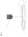
- the reverse prism type has a structure in which the reflective plate 12 adheres tightly to the light guide plate 13 due to the constitution of this type in Fig. 1 and therefore there readily causes a problem that inorganic particles are exfoliated to damage the light guide plate.
- the addition amount of the particles exceeds 0.5% by weight, the exfoliation of particles is apt to cause the flaws.
- the addition amount of the particles is preferably 0.5% by weight or less, and more preferably 0.1% by weight or less.
- a number average particle size of the particles added for this purpose is preferably 3 ⁇ m or more and 7 ⁇ m or less, and more preferably 3 to 5 ⁇ m. When the number average particle size on number is less than 3 ⁇ m, the roughness of the surface is lowered and adhesion between the film and the light guide plate may become high.
- the average particle size is more than 7 ⁇ m, since the particle becomes coarse, it tends to exfoliate and this may damage the light guide plate.
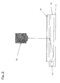
- the direct type since a cold cathode ray tube exists between the light guide plate and the reflective film, the light guide plate does not come into contact with the reflective film and there is not a possibility of occurrence of flaws of the light guide plate and the screen non-uniformity due to adhesion.
- the white polyester film of the present invention preferably has an applied layer containing spherical particles on at least one side of the white polyester film.
- an applied layer containing spherical particles, a projection shape is formed at the surface of the applied layer, and the light, which is reflected off the white film surface and passes through the applied layer, is concentrated by a lens effect through the projection shape at the surface of the applied layer and this contributes to improvement in the brightness in a front direction of a backlight.
- a type of the spherical particle of the present invention is not particularly limited, and any of organic particles and inorganic particles can be employed.
- organic spherical particles acrylic resin particles, silicone resin particles, nylon resin particles, polystyrene resin particles, polyamide resin particles such as benzoguanamine, and urethane resin particles can be used.
- inorganic spherical particles silicon oxide, aluminum hydroxide, aluminum oxide, zinc oxide, barium sulfide, magnesium silicate, and mixtures thereof can be used. It is preferable to use the organic spherical particles from the viewpoint of dispersibility of the particles in a resin binder commonly used, ability to be applied and economy.
- acrylic polymers, polystyrene polymers, and copolymers of acrylic-based vinyl monomer and styrene-based vinyl monomer are preferable, and particularly, and copolymers of acrylic-based vinyl monomer and styrene-based vinyl monomer can be suitably used in the present invention because a refractive index can be changed by adjusting a copolymerization proportion of two kinds of vinyl monomers.
- a refractive index differential an absolute value of a difference in refractive indexes between the spherical particle contained in the applied layer and the binder resin constituting the applied layer.
- a refractive index differential an absolute value of a difference in refractive indexes between the spherical particle contained in the applied layer and the binder resin constituting the applied layer.
- the refractive index differential is preferably 0.08 or less, more preferably 0.05 or less, and particularly preferably 0.01 or less.
- the refractive index herein refers to a proportion in which the undulation (such as light) traveling in a straight line changes an angle of a traveling direction at an interface between mediums, and it is a vacuum-based substance-specific value, that is, an absolute refractive index. Since the refractive index is an observed wavelength-specific value, the refractive index differential is a difference between values measured at the same observed wavelength. For example, a refractive index of poly(methyl methacrylate), a typical acrylic resin, is 1.49 for light having a wavelength of 589.3 nm.
- the refractive index differential referred to herein refers to an absolute value of a difference between a refractive index of the spherical particle and a refractive index of the binder resin, and even when the refractive index of the spherical particle is smaller than that of the binder resin and the refractive index differential is a negative value, its absolute value, that is, a positive value is a refractive index differential.
- the refractive index of the spherical particle and “the refractive index of the binder” are determined as follows.
- the volume average particle size is not particularly limited as long as the projection shape is formed at the surface of the applied layer, but the volume average particle size is preferably 0.05 ⁇ m or more, more preferably 0.5 ⁇ m or more, furthermore preferably 1 ⁇ m or more, and particularly preferably 3 ⁇ m or more.
- an upper limit of the volume average particle size is not particularly limited, but it is preferably 100 ⁇ m or less since the ability to be applied may be poor if it exceeds 100 ⁇ m.
- a coefficient of variation CV of the volume average particle size is preferably 30% or less.
- the coefficient of variation CV herein refers to a value obtained by dividing a standard deviation of the volume average particle size by the volume average particle size. This coefficient of variation CV is measured by a method described in Example described later.
- the coefficient of variation CV is more preferably 20% or less, particularly preferably 15% or less, and the most preferably 10% or less.
- the CV value can be reduced by classifying the particles and removing the particles having an uneven particle size.
- the spherical particle is preferably nonporous from the viewpoint of improvement in reflectance and light resistance. If the spherical particle is porous, an area of refractive interface between the binder resin and the spherical particle increases, and therefore light loss due to internal diffusion is increased and the reflectance is apt to decrease. Further, when a light resistant resin is used as a binder resin of the applied layer, if the spherical particle is porous, the binder resin is penetrated into pores. Therefore, even if the binder resin is added in the same amount as that of the binder resin in a case where nonporous spherical particles are used, a thickness of the applied layer becomes relatively small and the light resistance may be deteriorated.
- the content of the spherical particles in the applied layer is not particularly limited as long as the reflectance is improved, but the content of the spherical particle is preferably 3% by weight or more with respect to the whole applied layer, though it cannot be uniquely limited because it depends on the types of the particle and the dispersibility of the particle in a coating solution.
- the content is more preferably 5% by weight or more, furthermore preferably 10% by weight or more, and particularly preferably 15% by weight or more.
- an upper limit of the content is not particularly limited, but the content is preferably 30% by weight or less since the ability to be applied may be poor if it exceeds 30% by weight.
- the spherical particle When the applied layer is provided, since the spherical particle needs to be dispersed in a solvent during an applying step, the spherical particle requires solvent resistance and therefore the spherical particles preferably have a crosslinking structure. When the spherical particles do not have a crosslinking structure, the spherical particles are eluted during the applying step and there may be cases where the applied layer in which particle shapes and particle sizes are maintained cannot be provided.
- crosslinking structure it is preferable to form the crosslinking structure by use of vinyl compounds having a plurality of functional groups in a molecule, and it is particularly preferable to use polyfunctional acrylic compounds such as difunctional acrylic compounds, trifunctional acrylic compounds, and at least tetrafunctional acrylic compounds as vinyl compounds having a plurality of functional groups in a molecule
- TECHPOLYMER manufactured by SEKISUI PLASTICS Co., Ltd.
- S series in the "TECHPOLYMER” products are preferable, and when a coefficient of variation is 15% or less, spherical particles made of a copolymer of methyl methacrylate and ethylene glycol dimethacrylate such as SSX series products can be most suitably used.
- an ultraviolet absorber and/or a light stabilizer be added and that in producing these resins, the resin be chemically combined with an ultraviolet absorber and/or a light stabilizer, having a reactive double bond, by copolymerization. It is preferable to fix the ultraviolet absorber and/or the light stabilizer by chemically combining like the latter in that bleed out from the spherical particle is less.
- the ultraviolet absorber and the light stabilizer contained in the spherical particle are broadly divided into inorganic agents and organic agents.
- titanium oxide, zinc oxide, cerium oxide and the like are commonly known, and among them, zinc oxide is the most preferable in point of economy, an ultraviolet absorbing property and photocatalyst activity.
- organic-based ultraviolet absorbers may include benzotriazole-based, benzophenone-based, oxalic anilide-based, cyanoacrylate-based and triazine-based ultraviolet absorbers. Since these ultraviolet absorbers just absorb ultraviolet rays and cannot capture organic radicals produced by ultraviolet irradiation, this radical may cause chain reaction degradation of a white film to become a substrate. It is preferable to use the ultraviolet absorber in combination with the light stabilizer in order to capture these radicals and particularly a light stabilizer of a hindered amine-based compound is suitably used.
- acrylic-based or styrene-based vinyl monomers are preferable because of high general versatility and economy. Since styrene-based vinyl monomers have aromatic rings and are susceptible to yellowing, they are the most preferably copolymerized with the acrylic-based vinyl monomer from the viewpoint of light resistance.
- a reactive vinyl monomer-substituted benzotriazole 2-(2'-hydroxy-5'-methacryloxyethylphenyl)-2H-benzotriazole (trade name: RUVA-93, manufactured by Otsuka Chemical Co., Ltd.) can be used.
- a reactive vinyl monomer-substituted hindered amine compound 4-methacryloyloxy-2,2,6,6-tetramethylpiperidyne ("ADK STAB LA-82" manufactured by Adeka Argus Industry Co., Ltd.) can be used.
- copolymer components and monomer composition of the binder resin be identical to those of the spherical particle. Furthermore, when both of the binder resin and the spherical particle are composed of resins to which an ultraviolet absorber and/or a light stabilizer is added, the light resistance of the applied layer can also be improved.
- the white film of a substrate may be deteriorated (e.g., photodeterioration such as yellowing, or degradation in which a molecular weight is decreased) during being used as a backlight by light, particularly ultraviolet rays, emitted from a lamp of a cold cathode ray tube or the like, and therefore it is preferable that the ultraviolet absorber and/or the light stabilizer be contained in a layer of the white film of a substrate and/or in the binder resin layer provided on one side.
- the ultraviolet absorber and/or the light stabilizer be contained in a layer of the white film of a substrate and/or in the binder resin layer provided on one side.
- Materials of the binder resin layer is not particularly limited, but resins principally containing organic components are preferable and examples of the resins include polyester resin, polyurethane resin, acrylic resin, methacrylic resin, polyamide resin, polyethylene resin, polypropylene resin, polyvinyl chloride resin, polyvinylidene chloride resin, polystyrene resin, polyvinyl acetate resin, and fluorine-based resins. These resins may be used alone or as a copolymer or a mixture of two or more kinds of them. Among them, the polyester resin, the polyurethane resin, and acrylic or methacrylic resin are preferably used from the viewpoint of heat resistance, dispersibility of particles, an ability to be applied and a gloss level. From the viewpoint of the light resistance of the applied layer, it is more preferable that the binder resin layer also contain an ultraviolet absorber and a light stabilizer.
- a resin constituting a resin layer containing an ultraviolet absorber is not particularly limited, and resins containing an inorganic ultraviolet absorber, resins containing an organic ultraviolet absorber, and resins formed by copolymerizing a benzotriazole-based or a benzophenone-based reactive monomer can be used.
- organic ultraviolet absorbing resins containing a resin formed by copolymerizing a hindered amine (HALS)-based reactive monomer and the like are preferably used.
- the inorganic-based ultraviolet absorber zinc oxide, titanium oxide, cerium oxide and zirconium oxide are common.
- these absorbers at least one selected from the group consisting of zinc oxide, titanium oxide and cerium oxide is preferably used because it does not cause bleed out and has an excellent light resistance.
- Such ultraviolet absorber may be used in combination of several kinds as required.
- zinc oxide is the most preferable in point of economy, an ultraviolet absorbing property and photocatalyst activity.
- FINEX-25 LP, FINEX-50 LP manufactured by Sakai Chemical Industry Co., Ltd.
- organic-based ultraviolet absorbers resins containing an organic ultraviolet absorber such as benzotriazole and benzophenone, resins formed by copolymerizing a benzotriazole-based or a benzophenone-based reactive monomer, or resins formed by copolymerizing these resins with a light stabilizer such as a hindered amine (HALS)-based reactive monomer can be used.
- an organic ultraviolet absorber such as benzotriazole and benzophenone
- a light stabilizer such as a hindered amine (HALS)-based reactive monomer
- resins formed by copolymerizing a benzotriazole-based or a benzophenone-based reactive monomer and organic ultraviolet absorbing resins containing a resin formed by copolymerizing a hindered amine (HALS)-based reactive monomer with the resins are more preferable because of a large effect of absorbing ultraviolet light in a thin layer.
- HALS hindered amine
- HALSHYBRID registered trademark
- NIPPON SHOKUBAI CO., LTD. a copolymer of an acrylic monomer and an ultraviolet absorber as an active component, and the like
- copolymer components, monomer composition, ultraviolet absorbers and light stabilizers of the resin binder be identical to those of the spherical particle.
- purity of terephthalic acid being a base of polyethylene terephthalate is increased to reduce a total amount of metal catalyst compounds such as compounds using an element group of Sb, K, P, Mg, Li, Ca, Ge and Ti at the time of forming polyester being a base by polymerization, and by controlling reaction time and reaction temperature, polyethylene terephthalate, which has less catalyst residue and has a high L value and a low b value, is obtained.
- metal catalyst compounds such as compounds using an element group of Sb, K, P, Mg, Li, Ca, Ge and Ti
- polymethylpentene as a non-compatible polymer and polyethylene glycol and a copolymer of polybutylene terephthalate and polytetramethylene glycol as a specific gravity-decreasing material are mixed in the polyethylene terephthalate formed by polymerization by the above method, and the resulting mixture is adequately mixed and dried, and then supplied to an extruder A heated to a temperature of 270 to 300°C.
- polyethylene terephthalate including inorganic additives such as SiO 2 may be supplied to an extruder B by a common method, and a layer of the extruder A and a layer of the extruder B may be laminated in a three-layer constitution of layer A/layer B/layer A in a T-die three-layer nozzle so that a polymer of the layer of the extruder B becomes both surface layers.
- This melted sheet was brought into close contact with a drum, a surface temperature of which is cooled to 10 to 60°C, by an electrostatic force, cooled, and solidified to obtain a non-stretched film, and the non-stretched film is guided to a series of rolls heated to a temperature of 80 to 120°C, stretched by 2.0 to 5.0 times in a longitudinal direction, and cooled with a series of rolls of 20 to 50°C. Subsequently, the film stretched in a longitudinal direction was led to a tenter while grasping both ends of the film with clips, and was transversely stretched in a direction perpendicular to a longitudinal direction in an atmosphere heated to a temperature of 90 to 140°C.
- the film is stretched by 2.5 to 4.5 times in a longitudinal or transverse direction, but a ratio of area of the stretched film to original area (longitudinal draw ratio ⁇ transverse draw ratio) is preferably 9 to 16.
- a ratio of area of the stretched film to original area is preferably 9 to 16.
- whiteness of the resulting film becomes poor, and when the ratio is more than 16, the film is apt to break in stretching and a film forming property tends to become poor.
- the film is subjected to heat setting at a temperature of 150 to 230°C in the tenter and is slowly cooled uniformly to room temperature and wound to obtain a film of the present invention.
- additives may be added to the white film and/or the applied layer of the present invention within the range of not impairing the effects of the present invention.
- additives for example, organic and/or inorganic fine particles, fluorescent brighteners, crosslinking agents, heat stabilizers, antioxidants, organic lubricants, antistatic agents, nucleating agents, dyes, fillers, dispersants, coupling agents and the like can be used.
- an average reflectance at a wavelength of 400 to 700 nm measured from a plane in which the applied layer is provided is preferably 85% or more, more preferably 87% or more, and particularly preferably 90% or more.
- the average reflectance is less than 85%, some liquid crystal displays to which the white film of the present invention is applied may be low in brightness.
- the applied layer is provided on both sides of the white film, the average reflectance measured from any one of applied layers on both sides may be 85% or more.
- a coating solution may be applied by any method.
- the methods such as gravure coating, roller coating, spin coating, reverse coating, bar coating, screen coating, blade coating, air knife coating, and dipping may be employed.
- the coating solution for forming the applied layer may be applied (in line coating) concurrently with the production of the white film of a substrate may be used, or may be applied (off line coating) onto a white film in which the crystalline orientation has been completed.
- the white reflective film of the present invention thus obtained can realize an improvement in the brightness of the liquid crystal backlight, and in accordance with the further preferred aspect, the white reflective film can be favorably used as reflective plates for area light sources of edge-light and direct type for a liquid crystal screen and as reflectors since the reduction in reflectance is low even long-term use.
- the white reflective film of the present invention is used in these area light sources, it is installed with its applied layer directed to the light sources.
- the white polyester film for a liquid crystal display reflective plate of the present invention thus obtained has fine air bubbles formed within the film to achieve a high reflectance and can attain high brightness when it is used as a reflective plate of side light type liquid crystal displays and direct type liquid crystal displays.
- the spectral reflectance at a wavelength range of 450 to 600 nm is measured.
- R represents a light reflectance (%)
- ⁇ represents a wavelength of light (nm)
- M represents a wavelength coefficient (%/nm)
- B represents a constant (%)
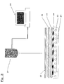
- a reflective film 12 of a backlight of VAIO (VGN-S52B/S) manufactured by SONY Corp. is changed to a prescribed film and the brightness is measured at a measuring distance of 850 mm with a luminance colorimeter 15 (BM-7 fast manufactured by Topcon Cord .). Measurement is performed three times and averaged.
- the brightness was rated according to the following criteria. 3000 cd/m 2 or more is excellent, 2950 cd/m 2 or more and less than 3000 cd/m 2 is good, 2900 cd/m 2 or more and less than 2950 cd/m 2 is acceptable, and less than 2900 cd/m 2 is bad.
- a reflective film bonded in a backlight of 181BLM07 (manufactured by NEC Corp.) was changed to a prescribed film sample and a liquid crystal display was lit up.
- the film sample was held for one hour in this state to stabilize a light source, and a screen portion of a liquid crystal display was taken with a CCD camera (DXC-390 manufactured by SONY Corp.) and images were captured by an image analyzer EyeScale manufactured by I.System Corp. Thereafter, the brightness level of the taken images was controlled in 30000 steps and automatically detected and detected data was converted to brightness.
- the brightness was rated according to the following criteria.
- 5100 cd/m 2 or more is excellent, 5000 cd/m 2 or more and less than 5100 cd/m 2 is good, 4900 cd/m 2 or more and less than 5000 cd/m 2 is acceptable, and less than 4900 cd/m 2 is bad.
- the gloss level was measured at an incident angle of 60 degrees and an acceptance angle of 60 degrees according to JIS K 7105 with a digital variable gloss meter (UGU-4D) manufactured by SUGA TEST INSTRUMENTS Co., Ltd.
- a reflective film 12 of a backlight of VAIO (VGN-S52B/S) manufactured by SONY Corp. was changed to a prescribed film and the prescribed film was brought into contact with the light guide plate 13, then the reflective film was removed, the surface of the light guide plate was observed, and the presence or absence of the flaw was visually identified.
- the flaw of the light guide plate the light guide plate having no flaw is good, the light guide plate having a few flaws is acceptable, and the light guide plate having flaws and being at an impracticable level is bad.
- a reflective film 12 of a backlight of VAIO (VGN-S52B/S) manufactured by SONY Corp. was changed to a prescribed film and a liquid crystal display was lit up in this state.
- a metal plate on a backside of a liquid crystal display was removed, a back of the reflective plate was pressed with a forefinger, and the brightness unevenness of the screen at that time was visually identified.
- the display in which the screen non-uniformity due to adhesion has not occurred, is excellent, the display, in which the screen non-uniformity due to adhesion has occurred but an area of the screen non-uniformity is less than 2 mm ⁇ 2 mm, is good, the display, in which the screen non-uniformity due to adhesion has occurred but an area of the screen non-uniformity is 2 mm ⁇ 2 mm or more and less than 5 mm ⁇ 5 mm, is acceptable, and the display, in which the screen non-uniformity due to adhesion has occurred but an area of the screen non-uniformity is 5 mm ⁇ 5 mm or more, is bad.
- the area of the screen non-uniformity indicates a region where the distribution of the screen brightness is uneven and a region which looks like bright whitish portion over the backlight, due to its adhesion to the light guide plate.
- the refractive indexes of the binder resin and the spherical particle are unknown, they are determined according the following procedure.
- a volume average particle size and a coefficient of variation CV of the spherical particles sampled in (11) were measured using Coulter Multisizer III (manufactured by Beckman Coulter, Inc.) as a particle size distribution measuring apparatus utilizing a pore electric resistance method. Number of particles and,a particle volume were measured by measuring electric resistance of an electrolyte fraction corresponding to a volume of particles at the time when the particles pass through the pores.
- a trace amount of samples were dispersed in a dilute aqueous solution of a surfactant, then this dispersion was added to a container of a designated electrolyte by a quantity in which a percentage of passing through an aperture (pore at detection section) was 10 to 20% while monitoring the display, measurement of a particle size was continued until number of particles passing through the pore reached 100000, and data was automatically calculated to determine a volume average particle size, and a standard deviation and a coefficient of variation of the volume average particle size.
- the coefficient of variation can be calculated from the following formula.
- ⁇ Coefficient of variation CV % standard deviation ⁇ m of volume average particle size ⁇ 100 / volume average particle size ⁇ m
- a b value representing a degree of yellow was determined by a reflection measuring method with a C/2° light source. b values of three samples were calculated and this was taken as a degree of yellow.
- Class A Change Rate in Yellowing is less than 5
- Class B Change Rate in Yellowing is not less than 5 and less than 15
- Class C Change Rate in Yellowing is not less than 15.
- a cold cathode ray tube lamp was lit up for 60 minutes to stabilize a light source and then brightness (cd/m 2 ) was measured using a luminance colorimeter model BM-7 fast (manufactured by TOPCON Corp.). An average value of brightness of three samples was determined and this average value was taken as average brightness.
- polyethylene terephthalate where a total amount of Sb, K, P, Mg, Li, Ca, Ge and Ti compounds, catalysts used in polymerization of polyethylene terephthalate, was 2.985 moles per 1 ton of polyethylene terephthalate and which was formed by polymerizing polyethylene glycol having a molecular weight of 4000 has an L value of 62.8 and a b value of 0.5 in color tone (according to JIS K 7105) as well as a haze value of 0.2%, 65 parts by weight of polyethylene terephthalate, .5 parts by weight of a copolymer of polybutylene terephthalate and polytetramethylene glycol (PBT/PTMG) (trade name: Hytrel manufactured by DU PONT-TORAY Co., Ltd.), 10 parts by weight of a copolymer formed by copolymerizing polyethylene terephthalate, 10 mol% of isophthalic acid and 5 mol% of polyethylene glycol having a
- a non-stretched film obtained by cooling and solidifying this film on a chill drum having a surface temperature of 25°C was guided to a series of rolls heated to a temperature of 85 to 98°C, stretched by 3.4 times in a longitudinal direction, and cooled with a series of rolls of 21°C. Subsequently, the film stretched in a longitudinal direction was led to a tenter while grasping both ends of the film with clips, and stretched by 3.6 times in a direction perpendicular to a longitudinal direction under an atmosphere heated to 120°C. Thereafter, the film was subjected to heat setting at 190°C in the tenter, and was slowly cooled uniformly to room temperature and wound to obtain a film having a thickness of 300 ⁇ m. The gloss level (60 degrees) of the resulting film was 122%.
- Properties as a substrate for a direct type liquid crystal display reflective plate are as shown in Table 1. High brightness was achieved in the direct type liquid crystal display.
- a film having a thickness of 300 ⁇ m was prepared by the same procedure as in Example 1 except for changing the composition of the polyester layer (A) to that described in Table 1.
- the gloss level (60 degrees) of the resulting film was 120%.
- Properties as a substrate for a direct type liquid crystal display reflective plate are as shown in Table 1. High brightness was achieved in the direct type liquid crystal display.
- a film having a thickness of 300 ⁇ m was prepared by the same procedure as in Example 1 except for changing the composition of the polyester layer (A) to that described in Table 1.
- the gloss level (60 degrees) of the resulting film was 42%.
- Properties as a substrate for a liquid crystal display reflective plate are as shown in Table 1. Very high brightness was achieved in the direct type liquid crystal display.
- a film having a thickness of 300 ⁇ m was prepared by the same procedure as in Example 1 except for changing the composition of the polyester layer (A) to that described in Table 1.
- the gloss level (60 degrees) of the resulting film was 55%.
- Properties as a substrate for a liquid crystal display reflective plate are as shown in Table 1. Very high brightness was achieved in the direct type liquid crystal display.
- a film having a thickness of 225 ⁇ m was prepared by the same procedure as in Example 1 except for changing the composition of the polyester layer (A) to that described in Table 1.
- the gloss level (60 degrees) of the resulting film was 56%.
- Properties as a substrate for a liquid crystal display reflective plate are as shown in Table 1. Very high brightness was achieved in the edge light type liquid crystal display and the direct type liquid crystal display.
- a film having a thickness of 250 ⁇ m was prepared by the same procedure as in Example 1 except for changing the compositions of the polyester layers (A) and (B) to those described in Table 1.
- the gloss level (60 degrees) of the resulting film was 113%.
- Properties as a substrate for a side light type and a direct type liquid crystal display reflective plates are as shown in Table 1. There was no flaw on the light guide plate and screen non-uniformity due to adhesion was not produced. Further, very high brightness was achieved in the edge light type liquid crystal display and the direct type liquid crystal display.
- a film having a thickness of 300 ⁇ m was prepared by the same procedure as in Example 1 except for changing the composition of the polyester layer (A) to that described in Table 1 and changing the lamination constitution of the layer A and the layer B from a three-layer to a two-layer.
- the gloss level (60 degrees) of the resulting film was 120%.
- Properties as a substrate for a side light type and a direct type liquid crystal display reflective plates are as shown in Table 1. There are a few flaws on the light guide plate but this film can be used in the application of the direct type liquid crystal display. Further, high brightness was achieved in the side light type liquid crystal display and the direct type liquid crystal display.
- a film having a thickness of 225 ⁇ m was prepared by the same procedure as in Example 1 except for changing the compositions of the polyester layers (A) and (B) to those described in Table 1.
- the gloss level (60 degrees) of the resulting film was 114%.
- Properties as a substrate for a side light type and a direct type liquid crystal display reflective plates are as shown in Table 1. There was no flaw on the light guide plate, screen non-uniformity due to adhesion was not produced, and very high brightness was achieved.
- a film having a thickness of 250 ⁇ m was prepared by-the same procedure as in Example 1 except for changing the composition of the polyester layer (A) to that described in Table 1.
- the gloss level (60 degrees) of the resulting film was 115%.
- Properties as a substrate for a side light type and a direct type liquid crystal display reflective plates are as shown in Table 1. There was no flaw on the light guide plate, a degree of screen non-uniformity due to adhesion was low, and high brightness was achieved in the edge light type liquid crystal display and the direct type liquid crystal display.
- a film having a thickness of 188 ⁇ m was prepared by the same procedure as in Example 1 except for changing the compositions of the polyester layers (A) and (B) to those described in Table 1.
- the gloss level (60 degrees) of the resulting film was 104%.
- Properties as a substrate for a side light type and a direct type liquid crystal display reflective plates are as shown in Table 1. There was no flaw on the light guide plate, screen non-uniformity due to adhesion was not produced, and high brightness was achieved in the edge light type liquid crystal display and the direct type liquid crystal display.
- a film having a thickness of 188 ⁇ m was prepared by the same procedure as in Example 1 except for changing the composition of the polyester layer (A) and a thickness of the film to those described in Table 1.
- the gloss level (60 degrees) of the resulting film was 48%.
- Properties as a substrate for a side light type and a direct type liquid crystal display reflective plates are as shown in Table 1.
- a level of the flaw of the light guide plate was impracticable but screen non-uniformity due to adhesion was not produced. High brightness was not achieved in the edge light type liquid crystal display nor the direct type liquid crystal display.
- a film having a thickness of 300 ⁇ m was prepared by the same procedure as in Example 1 except for changing the composition of the polyester layer (A) to that described in Table 1.
- the gloss level (60 degrees) of the resulting film was 99%.
- Properties as a substrate for a side light type and a direct type liquid crystal display reflective plates are as shown in Table 1. The flaw of the light guide plate was no problem but screen non-uniformity due to adhesion was found. High brightness was not achieved in the side light type liquid crystal display nor the direct type liquid crystal display.
- a film having a thickness of 250 ⁇ m was prepared by the same procedure as in Comparative Example 1 except for changing the compositions of the polyester layers (A) and (B) and a thickness of the film to those described in Table 1.
- the gloss level (60 degrees) of the resulting film was 27%.
- Properties as a substrate for a side light type and a direct type liquid crystal display reflective plates are as shown in Table 1. A level of the flaw of the light guide plate was impracticable but screen non-uniformity due to adhesion was not found. High brightness was not achieved in the side light type liquid crystal display nor the direct type liquid crystal display.
- a film having a thickness of 188 ⁇ m was prepared by the same procedure as in Example 1 except for changing the compositions of the polyester layers (A) and (B) and a thickness of the film to those described in Table 1.
- the gloss level (60 degrees) of the resulting film was 26%.
- Properties as a substrate for a side light type and a direct type liquid crystal display reflective plates are as shown in Table 1. A level of the flaw of the light guide plate was impracticable but screen non-uniformity due to adhesion was not found. High brightness was not achieved in the side light type liquid crystal display nor the direct type liquid crystal display.
- a film having a thickness of 100 ⁇ m was prepared by the same procedure as in Example 1 except for adjusting the composition of the polyester layer (A) so as to have the same composition as that of the polyester layer (B) and changing a thickness of the film to that described in Table 1.
- the gloss level (60 degrees) of the resulting film was 35%.
- Properties as a substrate for a side light type and a direct type liquid crystal display reflective plates are as shown in Table 1. A level of the flaw of the light guide plate was impracticable but screen non-uniformity due to adhesion was not found. High brightness was not achieved in the side light type liquid crystal display nor the direct type liquid crystal display.
- a coating solution formed by adding 10.0 parts by weight of HALSHYBRID (registered trademark) UV-G13 (acrylic copolymer, solution having a concentration of 40%, refractive index 1.49, manufactured by NIPPON SHOKUBAI CO., LTD.), 9.9 parts by weight of ethyl acetate, and 0.45 parts by weight of nonporous acrylic particles (manufactured by SEKISUI PLASTICS Co., Ltd., TECHPOLYMER (registered trademark) SSX series, SSX-105, refractive index 1.49, volume average particle size 5.0 ⁇ m, coefficient of variation CV 9%, acrylic copolymer, crosslinked, without an ultraviolet absorber and a light stabilizer) as a spherical particle while stirring a mixture, was prepared.
- This coating solution was applied onto one surface of the polyester film of Example 8 with a coating bar No. 12 manufactured by Metava corporation and dried at 120°C for one minute to obtain a white film on which 4.0 g/m 2 of
- a coating solution formed by adding 10.0 parts by weight of HALSHYBRID (registered trademark) UV-G13 (acrylic copolymer, solution having a concentration of 40%, refractive index 1.49, manufactured by NIPPON SHOKUBAI CO., LTD.), 14.5 parts by weight of ethyl acetate, and 1.75 parts by weight of nonporous acrylic particles (manufactured by SEKISUI PLASTICS Co., Ltd., TECHPOLYMER (registered trademark) SSX series, SSX-105, refractive index 1.49, volume average particle size 5.0 ⁇ m, coefficient of variation CV 9%, acrylic copolymer, crosslinked, without an ultraviolet absorber and a light stabilizer) as a spherical particle while stirring a mixture, was prepared.
- This coating solution was applied onto one surface of the polyester film of Example 8 with a coating bar No. 12 manufactured by Metava corporation to obtain a white film on which 4.0 g/m 2 of the coating solution was applied.
- nonporous acrylic particles manufactured by SEKISUI PLASTICS Co., Ltd., TECHPOLYMER (registered trademark) SSX-102, refractive index 1.49, volume average particle size 2.5 ⁇ m, coefficient of variation CV 10%, acrylic copolymer, crosslinked, without an ultraviolet absorber and a light stabilizer
- nonporous acrylic particles manufactured by SEKISUI PLASTICS Co., Ltd., TECHPOLYMER (registered trademark) MBX series, XX-09FP, refractive index 1.49, volume average particle size 5.0 ⁇ m, coefficient of variation CV 27%, acrylic copolymer, crosslinked, without an ultraviolet absorber and a light stabilizer
- nonporous acrylic particles manufactured by SEKISUI PLASTICS Co., Ltd., TECHPOLYMER (registered trademark) MBX series, MB30X-8, refractive index 1.49, volume average particle size 8.0 ⁇ m, coefficient of variation CV 32%, acrylic copolymer, crosslinked, without an ultraviolet absorber and a light stabilizer
- porous acrylic particles manufactured by SEKISUI PLASTICS Co., Ltd., TECHPOLYMER (registered trademark) MBP series, MBP-8, refractive index 1.49, volume average particle size 8.0 ⁇ m, coefficient of variation CV 44%, acrylic copolymer, crosslinked, without an ultraviolet absorber and a light stabilizer
- the dispersion was cooled to room temperature and filtrated with a mesh filter having an opening of 40 ⁇ m to eliminate flocculated substances. There was no flocculated substance in the resulting dispersion and the filtration of the dispersion was very excellent.
- the resin particles dispersed in the dispersion thus filtrated have a volume average particle size of 6.4 ⁇ m and this resin particle was completely spherical.
- the dispersion of the resin particles was washed according to a normal method and then filtrated to separate the resin particles from a dispersion medium, and separated resin particles were dried and classified to obtain spherical particles A (coefficient of variation CV 15%).
- a coating solution formed by adding 10.0 parts by weight of HALSHYBRID (registered trademark) UV-G13 (acrylic copolymer, solution having a concentration of 40%, refractive index 1.49, manufactured by NIPPON SHOKUBAI CO., LTD.), 11.9 parts by weight of ethyl acetate, and 1.0 part by weight of spherical particles A (refractive index 1.49, average particle size 6.4 ⁇ m, coefficient of variation CV 15%, acrylic copolymer, crosslinked, ultraviolet absorber: benzotriazole, light stabilizer: hindered amine) while stirring a mixture, was prepared.
- This coating solution was applied onto one surface of the polyester film of Example 8 with a coating bar No.12 manufactured by Metava corporation and dried at 120°C for one minute to obtain a white film on which 4.0 g/m 2 of the coating solution was applied.
- nonporous silicon oxide (silica) particles manufactured by FUSO CHEMICAL Co., Ltd., QUARTRON (registered trademark) SP series, SP-3C, refractive index 1.45, volume average particle size 3.0 ⁇ m, coefficient of variation CV 16%, crosslinked, without an ultraviolet absorber and a light stabilizer
- nonporous silicone particles manufactured by GE-Toshiba Silicone Co., Ltd., Tospearl (registered trademark), Tospearl 145, refractive index 1.42, volume average particle size 4.5 ⁇ m, coefficient of variation CV 12%, crosslinked, without an ultraviolet absorber and a light stabilizer
- nonporous polystyrene particles manufactured by SEKISUI PLASTICS Co., Ltd., TECHPOLYMER (registered trademark) SBX series, SBX-8, refractive index 1.59, volume average particle size 8.0 ⁇ m, coefficient of variation CV 37%, styrene copolymer, crosslinked, without an ultraviolet absorber and a light stabilizer
- a coating solution formed by adding 10.0 parts by weight of HALSHYBRID (registered trademark) UV-G13 (acrylic copolymer, solution having a concentration of 40%, refractive index 1.49, manufactured by NIPPON SHOKUBAI CO., LTD.) and 18.9 parts by weight of toluene while stirring a mixture, was prepared.
- This coating solution was applied onto one surface of the polyester film of Comparative Example 4 with a coating bar No. 12 manufactured by Metava corporation and dried at 120°C for one minute to obtain a white film on which 4.0 g/m 2 of only the binder resin was applied.
- Nonporous benzoguanamine-formaldehyde condensate particles manufactured by NIPPON SHOKUBAI CO., LTD., EPOSTAR (registered trademark), EPOSTAR M05, refractive index 1.66, volume average particle size 5.2 ⁇ m, coefficient of variation CV 35%, polyamide resin particle, crosslinked, without an ultraviolet absorber and a light stabilizer
- EPOSTAR M05 refractive index 1.66
- volume average particle size 5.2 ⁇ m coefficient of variation CV 35%
- polyamide resin particle crosslinked, without an ultraviolet absorber and a light stabilizer
- Nonporous silica particles manufactured by FUJI SILYSIA CHEMICAL Ltd. SYLOPHOBIC 100 (registered trademark), refractive index 1.45, volume average particle size 2.5 ⁇ m, coefficient of variation CV 49%, polyamide resin particle, crosslinked, without an ultraviolet absorber and a light stabilizer
- SYLOPHOBIC 100 registered trademark
- refractive index 1.45 refractive index 1.45
- volume average particle size 2.5 ⁇ m, coefficient of variation CV 49% polyamide resin particle, crosslinked, without an ultraviolet absorber and a light stabilizer
- this coating solution was applied onto one surface of the polyester film of Comparative Example 4 with a coating bar No.12 manufactured by Metava corporation and dried at 120°C for one minute to obtain a white film on which 4.0 g/m 2 of the coating solution was applied.
Landscapes
- Physics & Mathematics (AREA)
- Chemical & Material Sciences (AREA)
- Optics & Photonics (AREA)
- General Physics & Mathematics (AREA)
- Health & Medical Sciences (AREA)
- Chemical Kinetics & Catalysis (AREA)
- Medicinal Chemistry (AREA)
- Polymers & Plastics (AREA)
- Organic Chemistry (AREA)
- Engineering & Computer Science (AREA)
- Manufacturing & Machinery (AREA)
- Nonlinear Science (AREA)
- Materials Engineering (AREA)
- Crystallography & Structural Chemistry (AREA)
- Mathematical Physics (AREA)
- Optical Elements Other Than Lenses (AREA)
- Laminated Bodies (AREA)
- Manufacture Of Macromolecular Shaped Articles (AREA)
Abstract
in which R is an approximation formula by a least square method and represents a light reflectance (%), λ represents a wavelength of light (nm), M represents a wavelength coefficient (%/nm), B represents a constant (%), and R560 represents an estimated reflectance obtained by introducing λ = 560 nm into the approximation formula R (%).
Description
- The present invention relates to a white polyester film for a light reflective plate. Particularly, the present invention relates to a white polyester film for a liquid crystal display reflective plate used in reflective plates for relatively compact reverse prism type liquid crystal displays such as laptop computers and mobile phones, for side light type liquid crystal displays using conventional BEF systems, and for direct type liquid crystal displays such as flat-screen televisions. Furthermore, the present invention relates to a super-white polyester film having an excellent reflective property of blue light.
- As a light source for liquid crystal displays, light sources of a backlight type in which light is irradiated from a backside of a display and a light reflective film described in Patent document 1 are heretofore widely used because they have an advantage that they are low-profile and can illuminate uniformly. When they are used, it is necessary to place a light reflective plate on the backside of a screen in order to prevent the escape of illuminating light to the backside of a screen. Since a small thickness and a high reflective property of light are required for this light reflective plate, white films whitened by containing fine air bubbles within the film and reflecting light at the interface of the air bubble are principally used as a light reflective plate.
- Formation of the fine air bubbles is achieved by dispersing a non-compatible polymer having a high-melting point finely in a film base material, for example polyester, and stretching (e.g., biaxial stretching) the resulting film. Voids (air bubbles) are formed around this non-compatible polymer particles during this stretching, and the void exhibits an effect on light reflection, and therefore the film can be whitened and a high reflectance can be attained (Patent document 2). Light reflected off the reflective plate is diffused and light other than light having upward directivity is reflected by a prism, and the reflection is repeated between the reflective plate and the prism, and light is ultimately sent to a liquid crystal cell in a state in which the directivity of light is enhanced. In this case, if reflection efficiency of the reflective plate is low or there are factors which cause light leakage or light decay in a system, since optical loss is produced during repetition of the reflection to deteriorate energy efficiency, the brightness of a screen is lowered or economy is deteriorated.
- Further, the light reflective plate is requested to reflect all color (wavelength) of light uniformly from the viewpoint of color reproducibility of a display.
- Furthermore, in order to prevent yellowing of the film due to ultraviolet rays emitted from a cold cathode ray tube, a white film prepared by laminating an ultraviolet absorbing layer is proposed (Patent documents 3 and 4).
- In these white films, various methods for improving properties on the brightness are disclosed. For example, for the purpose of improving the brightness in an edge light type, a method in which a light-shielding layer is provided on the film surface opposite to a light source is disclosed (Patent document 5). Further, a method, in which light diffuseness is controlled by selecting a difference in refractive indexes between a spherical particle and a binder and front brightness is improved by a light diffusion sheet, is disclosed (Patent document 6). Further, a method, in which brightness unevenness of a backlight is improved by controlling the diffuseness of a film surface on the light source side in a reflective sheet in a direct backlight, is disclosed (Patent document 7).
- Patent document 1: Japanese Unexamined Patent Publication No.
2003-160682 - Patent document 2: Japanese Examined Patent Publication No.
8-16175 - Patent document 3: Japanese Unexamined Patent Publication No.
2001-166295 - Patent document 4: Japanese Unexamined Patent Publication No.
2002-90515 - Patent document 5: Japanese Unexamined Patent Publication No.
2002-333510 - Patent document 6: Japanese Unexamined Patent Publication No.
2001-324608 - Patent document 7: Japanese Unexamined Patent Publication No.
2005-173546 - As one method for enhancing the reflection efficiency of the light reflective plate, there is a technique in which number of voids per unit area is increased by increasing a thickness of the white film. The present inventors tried this technique, but the brightness of a display was not so improved as expected and it was found that the wavelength dependency of spectral reflectance varied. That is, a light reflectance at a long wavelength is improved, but an improvement in a light reflectance at a short wavelength is small.
- It is an object of the present invention to solve such problems and provide a white polyester film for a light reflective plate, which can attain high brightness when it is used in a side light type liquid crystal display or a direct backlight type liquid crystal display.
- The white polyester film for a liquid crystal display reflective plate of the present invention to meet this object relates to:
- (1) A white polyester film for a light reflective plate, having a thickness of 200 µm or more, wherein, in at least one side (side A) of the white polyester film, M is M ≤ -0.0110 (%/nm) and R560 ≥ 100 (%) when the wavelength dependency of spectral reflectance at a wavelength of 450 to 600 nm is approximated according to the following approximation formula R:

in which R is an approximation formula by a least square method and represents a light reflectance (%),λ represents a wavelength of light (nm), M represents a wavelength coefficient (%/nm.), B represents a constant (%), and R560 represents an estimated reflectance obtained by introducing λ = 560 nm into the approximation formula R (%); - (2) The white polyester film for a light reflective plate according to (1), wherein a gloss level of the side A at an incident angle of 60 degrees is 100% or more;
- (3) The white polyester film for a light reflective plate according to (1) or (2), wherein a gloss level of the side (side B) opposite to the side A at an incident angle of 60 degrees is 70% or less;
- (4) A white polyester film for a light reflective plate, wherein the white polyester film has an applied layer containing spherical particles on at least one side of the white polyester film according to (1) and an absolute value of a difference in refractive indexes between the spherical particle and a binder resin constituting the applied layer is 0.10 or less;
- (5) The white polyester film for a light reflective plate according to (4), wherein said spherical particle is a nonporous resin particle and a coefficient of variation CV of a volume average particle size is 30% or less;
- (6) The white polyester film for a light reflective plate according to (4) or (5), wherein a resin constituting said spherical particle is at least one selected from the group consisting of acrylic resin, silicone resin, and polystyrene resin, acrylic copolymer, polystyrene copolymer, and copolymer of acrylic vinyl monomer and styrene vinyl monomer;
- (7) The white polyester film for a light reflective plate according to (6), wherein said spherical particle contains at least an acrylic resin and said acrylic copolymer is composed of a copolymer of methyl methacrylate and ethylene glycol dimethacrylate;
- (8) The white polyester film for a light reflective plate according to (6), wherein said spherical particles are particles having a crosslinking structure;
- (9) The white polyester film for a light reflective plate according to (4), wherein said spherical particle contains an ultraviolet absorber and/or a light stabilizer;
- (10) The white polyester film for a light reflective plate according to (9), wherein said ultraviolet absorber is at least one of ultraviolet absorbers selected from the group consisting of benzotriazole-based, benzophenone-based, oxalic anilide-based, cyanoacrylate-based and triazine-based ultraviolet absorbers;
- (11) The white polyester film for a light reflective plate according to (9), wherein said light stabilizer is a hindered amine-based light stabilizer;
- (12) The white polyester film for a light reflective plate according to (4), wherein a resin constituting said spherical particle contains the same monomer components as those of a binder resin constituting said applied layer;
- (13) The white polyester film for a light reflective plate according to claim 1, wherein said white film comprises a three-layer constitution of layer A/layer B/layer A, and the layer B is a layer containing air bubbles, and the layer A is a layer formed by including inorganic particles and/or organic particles in polyester and the content of the particles is 0.5% by weight or less with respect to the total weight of each layer A;
- (14) The white polyester film for a light reflective plate according to claim 1, wherein said white film comprises a three-layer constitution of layer A/layer B/layer A', the layer B is a layer containing air bubbles, and the layer A and/or the layer A' is a layer formed by including inorganic particles and/or organic particles in polyester and the thickness of the layer A' is 0.1 to 3 µm;
- (19) A lamp reflector for a liquid crystal backlight, wherein the white reflective film according to any one of (1) to (18) is provided with the applied layer face or side B directed to a light source side; and
- (20) A direct type liquid crystal backlight, wherein the white reflective film according to according to any one of (1) to (18) is provided with the applied layer face directed to a light source side.
- In accordance with the white polyester film for a liquid crystal display reflective plate of the present invention, unprecedented high brightness can be attained in side light type liquid crystal displays and direct backlight type liquid crystal displays. The present invention relates to a white polyester film and this white polyester film exhibits high reflective performance particularly in big direct backlight type liquid crystal displays such as a TV set. Further, the white polyester film for a liquid crystal display reflective plate of the present invention has high reflective performance as relatively compact side light type liquid crystal displays such as laptop computers and mobile phones.
- By forming a white reflective film in which on at least one side thereof a specific applied layer is provided, it is possible to absorb ultraviolet rays from a lamp, improve reflectance, and contribute to improvement in brightness of a backlight when applied to the backlight.
-
-
Fig. 1 is a schematic sectional view of a liquid crystal screen (reverse prism type) into which a reflective plate is incorporated. -
Fig. 2 is a schematic sectional view of a liquid crystal screen (normal prism type), into which a side light type reflective plate is incorporated, and a reverse prism type, and a schematic view of a measuring method of brightness of the reverse prism type. -
Fig. 3 is a schematic sectional view of a liquid crystal screen (direct type), into which a reflective plate is incorporated, and a schematic view of a measuring method of brightness of the direct type. -
- 11;
- cold cathode ray tube
- 12;
- reflective plate
- 13;
- light guide plate
- 14;
- prism sheet
- 15;
- luminance colorimeter
- 16;
- cold cathode ray tube
- 17;
- reflective plate
- 18;
- light guide plate
- 19;
- prism sheet
- 20;
- luminance colorimeter
- 21;
- reflective plate
- 22;
- cold cathode ray tube
- 23;
- milky white plate
- 24;
- diffusion plate
- 25;
- prism sheet
- 26;
- polarizing prism sheet
- 27;
- CCD camera
- 28;
- Image analyzer (EyeScale)
- A film of the present invention desirably has a thickness of 200 µm or more. When the thickness is less than 200 µm, preferable wavelength dependency of spectral reflectance is relatively easily attained but an absolute reflectance is hardly attained. The thickness is preferably 225 µm, and more preferably 300 µm. Further, when the thickness is more than 500 µm, a weigh of a panel may be increased when the film is incorporated into the liquid crystal display.
- In at least one side (side A) of the film of the present invention, M satisfies a relationship of M ≤ -0.0110 (%/nm) when the wavelength dependency of spectral reflectance at a wavelength of 450 to 600 nm is approximated according to the following approximation formula R:

in which R is an approximation formula by a least square method and represents a light reflectance (%), λ represents a wavelength of light (nm), M represents a wavelength coefficient (%/nm), and B represents a constant (%). - M satisfies preferably a relationship of M ≤ -0.0140 (%/nm), and more preferably a relationship of M ≤ -0.020 (%/nm). The lowest limit of M is not particularly specified, but it is preferable that M falls within a range of M ≥ -0.060 (%/nm) because the light reflective plate is requested to reflect all color (wavelength) of light uniformly from the viewpoint of color reproducibility of a display. M satisfies furthermore preferably a relationship of M ≥ -0.050 (%/nm). The film satisfying a relationship of a wavelength coefficient M ≤ -0.0110 (%/nm) is hitherto found in the films containing pigments, but R560 of these films is less than 100%.
- In the present invention, one of methods for satisfying a relationship of M ≤ -0.0110 (%/nm) is a method of removing light-scattering components and light-absorbing components in the film as far as possible.
- Light is scattered/absorbed by impurities, metal components (catalyst), unsaturated bonds and the like in the reflective film and loses energy in its process. In this time, a part of scattered light is consumed within the reflective film and becomes a component not contributing to the brightness of a screen. Its effect increases as a wavelength becomes short and a short wavelength region of the spectral reflectance becomes relatively low.
- Then, the slope M can fall within the region by adjusting the degree of purity of polymer, metal components (catalyst), and color tone of polymer. Herein, the degree of purity of polymer refers to a quantity of unsaturated bond in a polymer and a polymer having less unsaturated bond is preferably used in the film of the present invention. Further, the metal components (catalyst) comprise the following element group. Examples of the metal components (catalyst) include compounds using an element group of Sb, K, P, Mg, Li, Ca, Ge and Ti, but preferably, the amounts of the components are so small that polymerization of polymer may not be affected.
- As for color tone of the polymer, in color tone of material chips, a polymer having a high L value (brightness) and a low b value (degree of yellow) is preferably used. By reducing these light-scattering/absorbing components, a reflectance in a short wavelength region becomes relatively high and a slope M becomes small. The reflectance in a short wavelength region is improved as the slope M becomes small, and this contributes to the improvement in the brightness of a screen.
- In the present invention, it is necessary that an estimated reflectance R560 obtained by substitution of λ = 560 into the approximation formula be 100% or more in at least one side of the film. When the estimated reflectance is less than 100%, the brightness as backlights of a side light type liquid crystal display or a direct type liquid crystal display is deteriorated.
- In order to make the R560 100% or more, it is important that the film be whitened by containing fine voids within the film, as describe below, and when number of voids is increased, the reflectance R560 can be improved. The reflectance R560 is preferably 102% or more, and more preferably 104% or more. There is not an upper limit on the reflectance R560, but the reflectance R560 is preferably 110% or less because it is necessary to increase an addition amount of the void nucleus for increasing the reflectance R560 and in that case, a film forming property may become unstable.
- In one aspect of the film of the present invention, a gloss level (60 degrees) of at least one side (side A) is preferably 100% or more. The gloss level is more preferably 115% or more, and furthermore preferably 120% or more. When the gloss level is less than 100%, light is scattered, and therefore a part of the scattered light proceeds to an angle region where light is all reflected within a film, and it cannot escape from the film to decay until the light is scattered again.
- In order to make the gloss level 100% or more, it is important that number of inorganic or organic particles contained in the film be decreased. If the inorganic or organic particles having particle sizes similar to wavelengths of visible light are present in the vicinity of the film surface, the gloss level is reduced below 100%. Further, in many cases, since these particles have refractive indexes which are different from that of the film, light is also scattered within the film. This effect is significant in light of short wavelength and it is not preferable in the present invention that a large amount of particles be present within the film.
- Further, in another aspect of the film of the present invention, it is preferable to form a surface in which a gloss level at an incident angle of 60 degrees is 70% or less. Particularly, in the side light type backlight, since the incident angle of light is shallow, light needs to be diffused forward. And so, it is possible to preferably apply a surface in which a gloss level at an incident angle of 60 degrees is 70% or less by a method of controlling surface roughness. Examples of the method of controlling surface roughness include a method of adding particles having a refractive index close to that of a film matrix resin, and a method of thinning a layer A' to a thickness of 0.1 to 3 µm. When the layer A' is thinned, if a layer B is a layer including voids, the interface of the layer B becomes a rough surface due to the presence of the void and this rough interface resulting from the voids of the layer B can affect the layer A' to change the surface roughness. The thickness of the layer A' is preferably 0.5 to 2 µm, and more preferably 0.8 to 1.5 µm.
- Polyester constituting the present invention is a polymer prepared from diol and dicarboxylic acid by polycondensation. Representative examples of the dicarboxylic acids include terephthalic acid, isophthalic acid, phthalic acid, naphthalenedicarboxylic acid, adipic acid, and sebacic acid, and representative examples of diol include ethylene glycol, trimethylene glycol, tetramethylene glycol, and cyclohexane dimethanol. Specific examples of the Polyesters include polymethylene terephthalate, polytetramethylene terephthalate, polyethylene-p-oxybenzoate, poly(1,4-cyclohexylenedimethylene terephthalate), and polyethylene-2,6-naphthalenedicarboxylate. In the present invention, particularly, polyethylene terephthalate and polyethylene naphthalate are preferable.
- Naturally, these polyesters may be a homopolyester or a copolyester, and examples of the copolymer components include diol components such as diethylene glycol, neopentyl glycol and polyalkylene glycol; and dicarboxylic acid components such as adipic acid, sebacic acid, phthalic acid, isophthalic acid, 2,6-naphthalenedicarboxylic acid and 5-sodium sulfoisophthalic acid.
- Further, known various additives such as antioxidants and antistatic agents may be added to this polyester. As the polyester used in the present invention, polyethylene terephthalate is preferable. A polyethylene terephthalate film is superior in water resistance, durability and chemical resistance.
- The film of the present invention is preferably whitened by containing fine air bubbles within the film. Formation of the fine air bubbles is preferably achieved by dispersing a high-melting point polymer which is non-compatible with polyester finely in a film base material, for example polyester, and stretching (e.g., biaxial stretching) the resulting film. Voids (air bubbles) are formed around this non-compatible polymer particles upon this stretching, and the void generates a difference in refractive indexes between the resin and the air layer to reflect light, and therefore the film can be whitened and a high reflectance can be attained. The polymer non-compatible with polyester (hereinafter, sometimes abbreviated as non-compatible polymer) is, for example, a polymer having a melting point of 180°C or higher, selected from poly-3-methylbutene-1, poly-4-methylpentene-1, polyvinyl-t-butane, 1,4-trans-poly-2,3-dimethylbutadiene, polyvinylcyclohexane, polystyrene, polymethylstyrene, polydimethylstyrene, polyfluorostyrene, poly-2-methyl-4-fluorostyrene, polyvinyl t-butyl ether, cellulose triacetate, cellulose tripropionate, polyvinyl fluoride, amorphous polyolefin, cyclic olefins copolymer resin, and polychlorotrifluoroethylene. Among them, polyolefins, particularly polymethylpentene and cyclic olefin, are preferable for the polyester base material. Cyclic olefins copolymer resin is a copolymer of ethylene and at least one cyclic olefin selected from the group consisting of bicycloalkenes and tricycloalkenes.
- An addition amount of the non-compatible polymer (e.g., polyolefin) is preferably 5% by weight or more and 40% by weight or less, taking an amount of the whole layer containing the non-conipatible polymer as 100% by weight. The addition amount is more preferably 10% by weight or more and 30% by weight or less, and furthermore preferably 15% by weight or more and 25% by weight or less. When the addition amount is less than 5% by weight, an effect of whitening becomes low and a high reflectance is hardly attained, and when the addition amount is more than 25% by weight, mechanical properties such as strength of a film itself may become too small and there causes a problem that the film is apt to break in stretching and therefore productivity is deteriorated. With respect to a relationship between the addition amount of the non-compatible polymer and optical properties, number of void nucleuses increases and number of void layers increases as the addition amount of the non-compatible polymer increases, and therefore a reflectance is improved to contribute to improvement of brightness.
- In order to disperse the non-compatible polymer as a particle having a particle size of 0.2 to 5 µm, it is effective to add a specific gravity-decreasing material as a dispersion aid. The specific gravity-decreasing material is a compound having an effect of decreasing a specific gravity and specific compounds have such an effect. As the specific gravity-decreasing material, thermoplastic polyester elastomer is used. For example, representative examples thereof include polyalkylene glycols such as polyethylene glycol, methoxy polyethylene glycol, polytetramethylene glycol and polypropylene glycol, ethylene oxide/propylene oxide copolymer, sodium dodecylbenzene sulfonate, sodium alkylsulfonate, glyceryl monostearate, tetrabutylphosphonium, and p-aminobenzenesulfonate. In the case of the film of the present invention, particularly, polyalkylene glycols, among them, polyethylene glycol is preferable. Further, a copolymer of polybutylene terephthalate and polytetramethylene glycol is preferably used in order to improve the dispersibility of a non-compatible polymer. An addition amount of the specific gravity-decreasing material is preferably 3% by weight or more and 40% by weight or less, taking an amount of the whole layer containing the non-compatible polymer as 100% by weight. When the addition amount is less than 3% by weight, an effect of addition becomes low and the dispersibility of a polymer is deteriorated, and when the addition amount is more than 40% by weight, intrinsic characteristics of a base material of the film may be impaired. Such the specific gravity-decreasing material can be controlled by being added to a film base material polymer in advance to prepare a master polymer (master chip). With respect to a relationship between the specific gravity-decreasing material and optical properties, in a region from 3% by weight to 40% by weight, since a dispersion diameter becomes extremely small by adding a dispersion aid, number of void layers per the same thickness increases and the reflectance is improved, and this contributes to increase in brightness of a screen. In a region of more than 40% by weight, even if the addition amount is increased, a dispersion diameter may not become small and may have no effect.
- As described above, when the white polyester film contains fine air bubbles, thereby, the apparent specific gravity of the polyester film becomes lower than that of a common polyester film. If further adding the specific gravity-decreasing material, the specific gravity is further decreased. That is, a white and light film can be obtained. In order to reduce the weight of the white polyester film for a liquid crystal display of the present invention while maintaining mechanical properties as a substrate for a liquid crystal display reflective plate, it is preferable that the apparent specific gravity be 0.5 or more and 1.2 or less. The apparent specific gravity is preferably 0.5 or more and 1.0 or less, and more preferably 0.55 or more and 0.8 or less.
- In order to make the apparent specific gravity 0.5 or more and 1.2 or less, in the case of using the specific gravity-decreasing material, for example polymethylpentene having a specific gravity of 0.83, as described above, the specific gravity-decreasing material is contained in an amount 5% by weight or more and 25% by weight or less with respect to the total weight of all layers and the film is stretched by 2.5 times to 4.5 times. When the apparent specific gravity falls within the range of the present invention, it is possible to allow a large number of fine air bubbles to exist while maintaining film strength and a high reflectance can be attained. That is, when the white film of the present invention is used as a liquid crystal display reflective plate, it exhibits significantly excellent brightness in the brightness of a screen.
- Further, the constitution of the white polyester film for a liquid crystal display reflective plate may be a two-layer constitution of layer A/layer B, or may be a three-layer constitution of layer A/layer B/layer A, layer A/layer B/layer A' or layer A/layer B/layer C, or may be a multi-layer constitution of layer A/layer B/···/layer B/layer A, for example, constitutions composed of at least 20 layers and at most 3000 layers. It is preferable for achieving a high reflectance and a film forming property simultaneously that the layer B become a layer containing the foregoing fine air bubbles. In the case of forming layer A/layer B/layer A', the same material is used in the layer A and the layer A', but a thickness of the layer A' is made smaller than that of the layer A. A preferable thickness of the layer A' is 0.1 to 3 µm, and more preferably 0.5 to 2 µm. Further, it is preferable from the viewpoint of reducing light loss due to scattering and improving a mirror reflective property that the layer A (layer A') and/or the layer C corresponding to the surface of the film be layers formed by including inorganic particles and/or organic particles in polyester in an amount at least 0.01% by weight and at most 0.5% by weight, preferably at most 0.1% by weight, more preferably at most 0.07% by weight with respect to the total weight of the layer A and/or the layer C (layers containing inorganic particles and/or organic particles). When the particles are added, as described above, a mirror reflective property is improved and therefore the gloss level can be increased to 110% or more. However, when the addition amount of inorganic particles and/or organic particles is less than 0.01% by weight, since the surface becomes extremely smooth, the slidability of a flat surface is deteriorated and wind defects are apt to occur to decrease yield. The addition amount of inorganic particles and/or organic particles is preferably 0.01% by weight or more from the viewpoint of handling ability (prevention of surface flaws).
- Light diffuseness may be required depending on the form of other members of a backlight in which the reflective film is used. In this case, it is also possible to bring the gloss level into 70% or less by including more particles in the layer A'.
- As inorganic particles and/or organic particles contained in a surface layer of the film, particles of a material selected from the group consisting of calcium carbonate, silica, magnesium carbonate, zinc carbonate, titanium oxide, zinc oxide, cerium oxide, magnesium oxide, barium sulfate, zinc suLfide, calcium phosphate, alumina, mica, titanated mica, talc, clay, kaolin, lithium fluoride and calcium fluoride can be used. In the case of the present invention, silica is desirably used in order to maintain a high gloss of the surface.
- Herein, when a type of a backlight is a direct type, an addition amount of the particles is preferably ultimately 0% by weight, but since in this case slidability of the film is deteriorated and productivity is deteriorated, it is preferable to add a small amount of the particles. The addition amount of the particles preferably falls within the region in consideration of an effect on an M value resulting from light scattering due to particle addition.
- Further, the reverse prism type has a structure in which the
reflective plate 12 adheres tightly to thelight guide plate 13 due to the constitution of this type inFig. 1 and therefore there readily causes a problem that inorganic particles are exfoliated to damage the light guide plate. When the addition amount of the particles exceeds 0.5% by weight, the exfoliation of particles is apt to cause the flaws. The addition amount of the particles is preferably 0.5% by weight or less, and more preferably 0.1% by weight or less. - In the edge light type, if the planarity of the reflective film is too high, locations where the film strongly adheres to the light guide plate are generated to change a reflection angle there, and thereby, brightness unevenness in a liquid crystal screen may be produced. And so, it is commonly carried out that the adhesion of the reflective film to the screen is decreased by giving a certain degree of surface roughness to the surface. A number average particle size of the particles added for this purpose is preferably 3 µm or more and 7 µm or less, and more preferably 3 to 5 µm. When the number average particle size on number is less than 3 µm, the roughness of the surface is lowered and adhesion between the film and the light guide plate may become high. When the average particle size is more than 7 µm, since the particle becomes coarse, it tends to exfoliate and this may damage the light guide plate. On the other hand, in the direct type, since a cold cathode ray tube exists between the light guide plate and the reflective film, the light guide plate does not come into contact with the reflective film and there is not a possibility of occurrence of flaws of the light guide plate and the screen non-uniformity due to adhesion.
- The white polyester film of the present invention preferably has an applied layer containing spherical particles on at least one side of the white polyester film. By containing the spherical particles, a projection shape is formed at the surface of the applied layer, and the light, which is reflected off the white film surface and passes through the applied layer, is concentrated by a lens effect through the projection shape at the surface of the applied layer and this contributes to improvement in the brightness in a front direction of a backlight.
- A type of the spherical particle of the present invention is not particularly limited, and any of organic particles and inorganic particles can be employed. As the organic spherical particles, acrylic resin particles, silicone resin particles, nylon resin particles, polystyrene resin particles, polyamide resin particles such as benzoguanamine, and urethane resin particles can be used. As the inorganic spherical particles, silicon oxide, aluminum hydroxide, aluminum oxide, zinc oxide, barium sulfide, magnesium silicate, and mixtures thereof can be used. It is preferable to use the organic spherical particles from the viewpoint of dispersibility of the particles in a resin binder commonly used, ability to be applied and economy. Among them, acrylic polymers, polystyrene polymers, and copolymers of acrylic-based vinyl monomer and styrene-based vinyl monomer are preferable, and particularly, and copolymers of acrylic-based vinyl monomer and styrene-based vinyl monomer can be suitably used in the present invention because a refractive index can be changed by adjusting a copolymerization proportion of two kinds of vinyl monomers.
- When the applied layer is provided, it is preferable to adjust an absolute value (hereinafter, referred to as a refractive index differential) of a difference in refractive indexes between the spherical particle contained in the applied layer and the binder resin constituting the applied layer to 0.10 or less. As described above, when the applied layer contains the spherical particles, the brightness in a front direction of a backlight is improved. However, if there is the refractive index differential between the spherical particle and the binder resin, light, which is diffused at the interface between the spherical particle and the binder resin and reaches the surface of the applied layer, of the light, which is reflected off the white film surface and passes through the applied layer, is reduced. That is; light loss due to internal diffusion is increased and the reflectance is reversely reduced. And so, since by adjusting the refractive index differential to 0.10 or less, internally diffusing loss in the applied layer is reduced, light to reach the surface of the applied layer is relatively increased and the reflectance is improved. When the refractive index differential is more than 0.10, even if the white reflective film of the present invention is incorporated into the backlight, an effect of improving the brightness may not be achieved. The refractive index differential is preferably 0.08 or less, more preferably 0.05 or less, and particularly preferably 0.01 or less.
- The refractive index herein refers to a proportion in which the undulation (such as light) traveling in a straight line changes an angle of a traveling direction at an interface between mediums, and it is a vacuum-based substance-specific value, that is, an absolute refractive index. Since the refractive index is an observed wavelength-specific value, the refractive index differential is a difference between values measured at the same observed wavelength. For example, a refractive index of poly(methyl methacrylate), a typical acrylic resin, is 1.49 for light having a wavelength of 589.3 nm.
- The refractive index differential referred to herein refers to an absolute value of a difference between a refractive index of the spherical particle and a refractive index of the binder resin, and even when the refractive index of the spherical particle is smaller than that of the binder resin and the refractive index differential is a negative value, its absolute value, that is, a positive value is a refractive index differential.
- "The refractive index of the spherical particle", and "the refractive index of the binder" are determined as follows.
- (i) A binder resin is extracted from an applied layer by using an organic solvent and the organic solvent is distilled off, and then a refractive index of light is measured at 25°C at a wavelength of 589.3 nm with an ellipsometry method. Values obtained by this measurement are taken as "a refractive index of a binder resin".
- (ii) The applied layer of a white reflective film is immersed in an organic solvent, and the applied layer is peeled off from the white film and then the applied layer is pressed against a slide glass and slid on the slide glass to exfoliate spherical particles from the applied layer. A refractive index of the obtained spherical particle is determined according to a Becke's line detection method. Specifically, the particle is put in a liquid organic compound, and the particle in the liquid organic compound is observed at various liquid temperatures at which a refractive index of the liquid is known and the refractive index of the liquid organic compound at the time when the outline of the particle cannot be recognized is taken as "a refractive index of a spherical particle".
- The volume average particle size is not particularly limited as long as the projection shape is formed at the surface of the applied layer, but the volume average particle size is preferably 0.05 µm or more, more preferably 0.5 µm or more, furthermore preferably 1 µm or more, and particularly preferably 3 µm or more. When the volume average particle size is less than 0.05 µm, an effect of improving the brightness of a backlight may not be achieved. Further, an upper limit of the volume average particle size is not particularly limited, but it is preferably 100 µm or less since the ability to be applied may be poor if it exceeds 100 µm.
- In the spherical particles, a coefficient of variation CV of the volume average particle size is preferably 30% or less. The coefficient of variation CV herein refers to a value obtained by dividing a standard deviation of the volume average particle size by the volume average particle size. This coefficient of variation CV is measured by a method described in Example described later. The coefficient of variation CV is more preferably 20% or less, particularly preferably 15% or less, and the most preferably 10% or less. When the coefficient of variation CV is more than 30%, since the uniformity of the particles is poor, the diffuseness of light is intensified and an effect of improving the brightness of a backlight may become low. The CV value can be reduced by classifying the particles and removing the particles having an uneven particle size.
- The spherical particle is preferably nonporous from the viewpoint of improvement in reflectance and light resistance. If the spherical particle is porous, an area of refractive interface between the binder resin and the spherical particle increases, and therefore light loss due to internal diffusion is increased and the reflectance is apt to decrease. Further, when a light resistant resin is used as a binder resin of the applied layer, if the spherical particle is porous, the binder resin is penetrated into pores. Therefore, even if the binder resin is added in the same amount as that of the binder resin in a case where nonporous spherical particles are used, a thickness of the applied layer becomes relatively small and the light resistance may be deteriorated.
- The content of the spherical particles in the applied layer is not particularly limited as long as the reflectance is improved, but the content of the spherical particle is preferably 3% by weight or more with respect to the whole applied layer, though it cannot be uniquely limited because it depends on the types of the particle and the dispersibility of the particle in a coating solution. The content is more preferably 5% by weight or more, furthermore preferably 10% by weight or more, and particularly preferably 15% by weight or more. When the content is less than 3% by weight, an effect of improving the brightness of a backlight may not be achieved. Further, an upper limit of the content is not particularly limited, but the content is preferably 30% by weight or less since the ability to be applied may be poor if it exceeds 30% by weight.
- When the applied layer is provided, since the spherical particle needs to be dispersed in a solvent during an applying step, the spherical particle requires solvent resistance and therefore the spherical particles preferably have a crosslinking structure. When the spherical particles do not have a crosslinking structure, the spherical particles are eluted during the applying step and there may be cases where the applied layer in which particle shapes and particle sizes are maintained cannot be provided.
- In order to form the crosslinking structure, it is preferable to form the crosslinking structure by use of vinyl compounds having a plurality of functional groups in a molecule, and it is particularly preferable to use polyfunctional acrylic compounds such as difunctional acrylic compounds, trifunctional acrylic compounds, and at least tetrafunctional acrylic compounds as vinyl compounds having a plurality of functional groups in a molecule
- As the spherical particle, "TECHPOLYMER" (manufactured by SEKISUI PLASTICS Co., Ltd.) can be used. When a coefficient of variation is 30% or less, S series in the "TECHPOLYMER" products are preferable, and when a coefficient of variation is 15% or less, spherical particles made of a copolymer of methyl methacrylate and ethylene glycol dimethacrylate such as SSX series products can be most suitably used.
- In the spherical particles, it is preferable that an ultraviolet absorber and/or a light stabilizer be added and that in producing these resins, the resin be chemically combined with an ultraviolet absorber and/or a light stabilizer, having a reactive double bond, by copolymerization. It is preferable to fix the ultraviolet absorber and/or the light stabilizer by chemically combining like the latter in that bleed out from the spherical particle is less.
- The ultraviolet absorber and the light stabilizer contained in the spherical particle are broadly divided into inorganic agents and organic agents.
- As inorganic-based ultraviolet absorbers, titanium oxide, zinc oxide, cerium oxide and the like are commonly known, and among them, zinc oxide is the most preferable in point of economy, an ultraviolet absorbing property and photocatalyst activity.
- Examples of organic-based ultraviolet absorbers may include benzotriazole-based, benzophenone-based, oxalic anilide-based, cyanoacrylate-based and triazine-based ultraviolet absorbers. Since these ultraviolet absorbers just absorb ultraviolet rays and cannot capture organic radicals produced by ultraviolet irradiation, this radical may cause chain reaction degradation of a white film to become a substrate. It is preferable to use the ultraviolet absorber in combination with the light stabilizer in order to capture these radicals and particularly a light stabilizer of a hindered amine-based compound is suitably used.
- As copolymerization monomers to fix the organic-based ultraviolet absorbers and/or the light stabilizers, acrylic-based or styrene-based vinyl monomers are preferable because of high general versatility and economy. Since styrene-based vinyl monomers have aromatic rings and are susceptible to yellowing, they are the most preferably copolymerized with the acrylic-based vinyl monomer from the viewpoint of light resistance.
- As a reactive vinyl monomer-substituted benzotriazole, 2-(2'-hydroxy-5'-methacryloxyethylphenyl)-2H-benzotriazole (trade name: RUVA-93, manufactured by Otsuka Chemical Co., Ltd.) can be used. Further, as a reactive vinyl monomer-substituted hindered amine compound, 4-methacryloyloxy-2,2,6,6-tetramethylpiperidyne ("ADK STAB LA-82" manufactured by Adeka Argus Industry Co., Ltd.) can be used.
- Since if a difference in refractive indexes between the binder resin and the spherical particle in the applied layer is reduced as far as possible, the reflectance is improved, it is preferable that copolymer components and monomer composition of the binder resin be identical to those of the spherical particle. Furthermore, when both of the binder resin and the spherical particle are composed of resins to which an ultraviolet absorber and/or a light stabilizer is added, the light resistance of the applied layer can also be improved.
- In the white reflective film of the present invention, the white film of a substrate may be deteriorated (e.g., photodeterioration such as yellowing, or degradation in which a molecular weight is decreased) during being used as a backlight by light, particularly ultraviolet rays, emitted from a lamp of a cold cathode ray tube or the like, and therefore it is preferable that the ultraviolet absorber and/or the light stabilizer be contained in a layer of the white film of a substrate and/or in the binder resin layer provided on one side.
- Materials of the binder resin layer is not particularly limited, but resins principally containing organic components are preferable and examples of the resins include polyester resin, polyurethane resin, acrylic resin, methacrylic resin, polyamide resin, polyethylene resin, polypropylene resin, polyvinyl chloride resin, polyvinylidene chloride resin, polystyrene resin, polyvinyl acetate resin, and fluorine-based resins. These resins may be used alone or as a copolymer or a mixture of two or more kinds of them. Among them, the polyester resin, the polyurethane resin, and acrylic or methacrylic resin are preferably used from the viewpoint of heat resistance, dispersibility of particles, an ability to be applied and a gloss level. From the viewpoint of the light resistance of the applied layer, it is more preferable that the binder resin layer also contain an ultraviolet absorber and a light stabilizer.
- A resin constituting a resin layer containing an ultraviolet absorber is not particularly limited, and resins containing an inorganic ultraviolet absorber, resins containing an organic ultraviolet absorber, and resins formed by copolymerizing a benzotriazole-based or a benzophenone-based reactive monomer can be used.
- As a resin constituting a resin layer containing a light stabilizer, organic ultraviolet absorbing resins containing a resin formed by copolymerizing a hindered amine (HALS)-based reactive monomer and the like are preferably used.
- As the inorganic-based ultraviolet absorber, zinc oxide, titanium oxide, cerium oxide and zirconium oxide are common. Among these absorbers, at least one selected from the group consisting of zinc oxide, titanium oxide and cerium oxide is preferably used because it does not cause bleed out and has an excellent light resistance. Such ultraviolet absorber may be used in combination of several kinds as required. Among them, zinc oxide is the most preferable in point of economy, an ultraviolet absorbing property and photocatalyst activity. As the zinc oxide, FINEX-25 LP, FINEX-50 LP (manufactured by Sakai Chemical Industry Co., Ltd.) and the like can be used.
- As the organic-based ultraviolet absorbers, resins containing an organic ultraviolet absorber such as benzotriazole and benzophenone, resins formed by copolymerizing a benzotriazole-based or a benzophenone-based reactive monomer, or resins formed by copolymerizing these resins with a light stabilizer such as a hindered amine (HALS)-based reactive monomer can be used. Particularly, resins formed by copolymerizing a benzotriazole-based or a benzophenone-based reactive monomer, and organic ultraviolet absorbing resins containing a resin formed by copolymerizing a hindered amine (HALS)-based reactive monomer with the resins are more preferable because of a large effect of absorbing ultraviolet light in a thin layer.
- Methods for manufacturing these resins are disclosed in detail in paragraphs [0019] to [0039] of Japanese Unexamined Patent Publication No.
2002-90515 - As described previously, if a difference in refractive indexes between the resin binder and the spherical particle is reduced as far as possible, since the reflectance is improved and further the light resistance of the applied layer is also improved, it is preferable that copolymer components, monomer composition, ultraviolet absorbers and light stabilizers of the resin binder be identical to those of the spherical particle.
- Next, a method for manufacturing a white polyester film for a light reflective plate of the present invention will be described, but the present invention is not limited to this example.
- First, purity of terephthalic acid being a base of polyethylene terephthalate is increased to reduce a total amount of metal catalyst compounds such as compounds using an element group of Sb, K, P, Mg, Li, Ca, Ge and Ti at the time of forming polyester being a base by polymerization, and by controlling reaction time and reaction temperature, polyethylene terephthalate, which has less catalyst residue and has a high L value and a low b value, is obtained.
- Next, polymethylpentene as a non-compatible polymer, and polyethylene glycol and a copolymer of polybutylene terephthalate and polytetramethylene glycol as a specific gravity-decreasing material are mixed in the polyethylene terephthalate formed by polymerization by the above method, and the resulting mixture is adequately mixed and dried, and then supplied to an extruder A heated to a temperature of 270 to 300°C. If required, polyethylene terephthalate including inorganic additives such as SiO2 may be supplied to an extruder B by a common method, and a layer of the extruder A and a layer of the extruder B may be laminated in a three-layer constitution of layer A/layer B/layer A in a T-die three-layer nozzle so that a polymer of the layer of the extruder B becomes both surface layers.
- This melted sheet was brought into close contact with a drum, a surface temperature of which is cooled to 10 to 60°C, by an electrostatic force, cooled, and solidified to obtain a non-stretched film, and the non-stretched film is guided to a series of rolls heated to a temperature of 80 to 120°C, stretched by 2.0 to 5.0 times in a longitudinal direction, and cooled with a series of rolls of 20 to 50°C. Subsequently, the film stretched in a longitudinal direction was led to a tenter while grasping both ends of the film with clips, and was transversely stretched in a direction perpendicular to a longitudinal direction in an atmosphere heated to a temperature of 90 to 140°C. The film is stretched by 2.5 to 4.5 times in a longitudinal or transverse direction, but a ratio of area of the stretched film to original area (longitudinal draw ratio × transverse draw ratio) is preferably 9 to 16. When the ratio of area is less than 9, whiteness of the resulting film becomes poor, and when the ratio is more than 16, the film is apt to break in stretching and a film forming property tends to become poor. In order to impart planarity and dimensional stability to the film thus biaxially stretched, the film is subjected to heat setting at a temperature of 150 to 230°C in the tenter and is slowly cooled uniformly to room temperature and wound to obtain a film of the present invention.
- Various additives may be added to the white film and/or the applied layer of the present invention within the range of not impairing the effects of the present invention. As the additives, for example, organic and/or inorganic fine particles, fluorescent brighteners, crosslinking agents, heat stabilizers, antioxidants, organic lubricants, antistatic agents, nucleating agents, dyes, fillers, dispersants, coupling agents and the like can be used.
- In the white reflective plate of the present invention, an average reflectance at a wavelength of 400 to 700 nm measured from a plane in which the applied layer is provided is preferably 85% or more, more preferably 87% or more, and particularly preferably 90% or more. When the average reflectance is less than 85%, some liquid crystal displays to which the white film of the present invention is applied may be low in brightness. When the applied layer is provided on both sides of the white film, the average reflectance measured from any one of applied layers on both sides may be 85% or more.
- When the applied layer of the present invention is applied to a white film being a substrate, a coating solution may be applied by any method. The methods such as gravure coating, roller coating, spin coating, reverse coating, bar coating, screen coating, blade coating, air knife coating, and dipping may be employed. Further, the coating solution for forming the applied layer may be applied (in line coating) concurrently with the production of the white film of a substrate may be used, or may be applied (off line coating) onto a white film in which the crystalline orientation has been completed.
- The white reflective film of the present invention thus obtained can realize an improvement in the brightness of the liquid crystal backlight, and in accordance with the further preferred aspect, the white reflective film can be favorably used as reflective plates for area light sources of edge-light and direct type for a liquid crystal screen and as reflectors since the reduction in reflectance is low even long-term use. When the white reflective film of the present invention is used in these area light sources, it is installed with its applied layer directed to the light sources.
- The white polyester film for a liquid crystal display reflective plate of the present invention thus obtained has fine air bubbles formed within the film to achieve a high reflectance and can attain high brightness when it is used as a reflective plate of side light type liquid crystal displays and direct type liquid crystal displays.
- Methods of evaluation of properties and methods of evaluation of effects of the present invention are as follows.
- A reflectance in a case where an integrating sphere was attached to a spectrophotometer (U-3310) manufactured by Hitachi High-Technologies Corp. and a standard white plate (aluminum oxide) is taken as 100% is measured over a wavelength of 450 to 600 nm. The reflectance is read from the resulting chart at 5 nm intervals and this reflectance is taken as a spectral reflectance.
- In the method, in at least one side (side A) of the film, the spectral reflectance at a wavelength range of 450 to 600 nm is measured. The wavelength dependency of spectral reflectance is approximated according to the following approximation formula R:

by a least square method, based on spectral reflectance measured at 5 nm intervals to determine M (%/nm) and R560. - In the formula, R represents a light reflectance (%), λ represents a wavelength of light (nm), M represents a wavelength coefficient (%/nm), B represents a constant (%), and R560 represents an estimated reflectance obtained by introducing λ = 560 nm into the approximation formula R (%).
- A film is cut into the size of 100 mm × 100 mm, thicknesses of at least 10 points are measured with a measuring element with a dial gauge, and an average thickness d (µm) is calculated. Further, this film is weighed with a direct-reading balance to read out weight w (g) to an order of 10-4. Then, an apparent specific gravity = w/d × 100 is calculated.
- As shown in
Fig. 1 , areflective film 12 of a backlight of VAIO (VGN-S52B/S) manufactured by SONY Corp. is changed to a prescribed film and the brightness is measured at a measuring distance of 850 mm with a luminance colorimeter 15 (BM-7 fast manufactured by Topcon Cord .). Measurement is performed three times and averaged. The brightness was rated according to the following criteria.
3000 cd/m2 or more is excellent,
2950 cd/m2 or more and less than 3000 cd/m2 is good,
2900 cd/m2 or more and less than 2950 cd/m2 is acceptable, and
less than 2900 cd/m2 is bad. - As shown in
Fig. 3 , a reflective film bonded in a backlight of 181BLM07 (manufactured by NEC Corp.) was changed to a prescribed film sample and a liquid crystal display was lit up. The film sample was held for one hour in this state to stabilize a light source, and a screen portion of a liquid crystal display was taken with a CCD camera (DXC-390 manufactured by SONY Corp.) and images were captured by an image analyzer EyeScale manufactured by I.System Corp. Thereafter, the brightness level of the taken images was controlled in 30000 steps and automatically detected and detected data was converted to brightness. The brightness was rated according to the following criteria.
5100 cd/m2 or more is excellent,
5000 cd/m2 or more and less than 5100 cd/m2 is good,
4900 cd/m2 or more and less than 5000 cd/m2 is acceptable, and
less than 4900 cd/m2 is bad. - The gloss level was measured at an incident angle of 60 degrees and an acceptance angle of 60 degrees according to JIS K 7105 with a digital variable gloss meter (UGU-4D) manufactured by SUGA TEST INSTRUMENTS Co., Ltd.
- As shown in
Fig. 1 , areflective film 12 of a backlight of VAIO (VGN-S52B/S) manufactured by SONY Corp. was changed to a prescribed film and the prescribed film was brought into contact with thelight guide plate 13, then the reflective film was removed, the surface of the light guide plate was observed, and the presence or absence of the flaw was visually identified.
As evaluations of the flaw of the light guide plate,
the light guide plate having no flaw is good,
the light guide plate having a few flaws is acceptable, and
the light guide plate having flaws and being at an impracticable level is bad. - As shown in
Fig. 1 , areflective film 12 of a backlight of VAIO (VGN-S52B/S) manufactured by SONY Corp. was changed to a prescribed film and a liquid crystal display was lit up in this state. A metal plate on a backside of a liquid crystal display was removed, a back of the reflective plate was pressed with a forefinger, and the brightness unevenness of the screen at that time was visually identified.
As evaluations of the screen non-uniformity due to adhesion,
the display, in which the screen non-uniformity due to adhesion has not occurred, is excellent,
the display, in which the screen non-uniformity due to adhesion has occurred but an area of the screen non-uniformity is less than 2 mm × 2 mm, is good,
the display, in which the screen non-uniformity due to adhesion has occurred but an area of the screen non-uniformity is 2 mm × 2 mm or more and less than 5 mm × 5 mm, is acceptable, and the display, in which the screen non-uniformity due to adhesion has occurred but an area of the screen non-uniformity is 5 mm × 5 mm or more, is bad. - The area of the screen non-uniformity indicates a region where the distribution of the screen brightness is uneven and a region which looks like bright whitish portion over the backlight, due to its adhesion to the light guide plate.
- Using a transmission electron microscope Model HU-12 (manufactured by Hitachi Ltd.), cross sections of the layer A and/or the Layer C were observed at an observation magnification of 100000 times and to determine particle sizes from the photographs of the cross section. That is, an outline of a particle portion in the cross section photograph was traced, this particle portion was image-processed with a high-definition image analysis apparatus PIAS-IV (a manufactured by PIAS Corp.), images of 100 particles in a measuring field were converted to an equivalent circle to determine a number average particle size, and this number average particle size was taken as an average particle size of the inorganic and/or organic particles.
- 0.1 g (part) of the film sample was weighed out in a platinum crucible, and carbonized and incinerated with a gas burner, and the resulting residue was subjected to a fusion treatment by sodium carbonate-boric acid and then dissolved in diluted nitric acid. Insoluble matter was separated by filtration and incinerated, and was subjected to a heat fusion treatment by phosphoric acid and then dissolved in diluted nitric acid. This solution was analyzed using an ICP optical emission spectrometry apparatus (manufactured by SII NanoTechnology Inc., SPS 3100 (sequential type), and manufactured by PerkinElmer Co., Ltd., Optima 4300 DV (multi-type)).
- When the content of the spherical particle in the applied layer is unknown, it is determined according the following procedure.
- (i) The applied layer of the white reflective film is shaved off by a sharp knife, 0.05 g of the applied layer is sampled from the white film, and a binder resin component is extracted from this sample by using an organic solvent.
- (ii) A substance which is not dissolved in the organic solvent is considered as spherical particles, weight A (g) of the spherical particles is weighed, and a value calculated by the following equation is taken as "a content of spherical particles".

- When the refractive indexes of the binder resin and the spherical particle are unknown, they are determined according the following procedure.
- (i) A binder resin is extracted from an applied layer by using an organic solvent and the organic solvent is distilled off, and then a refractive index of light is measured at 25°C at a wavelength of 589.3 nm with an ellipsometry method. Values obtained by this measurement are taken as "a refractive index of a binder resin".
- (ii) The applied layer of a white reflective film is immersed in an organic solvent, the applied layer is peeled off from the white reflective film, and then the applied layer is pressed against a slide glass and slid on the slide glass to exfoliate spherical particles from the applied layer. A refractive index of the obtained spherical particle is determined according to a Becke's line detection method. Specifically, the particle is put in a liquid organic compound, the particle in the liquid organic compound is observed at various liquid temperatures at which a refractive index of the liquid is known, and the refractive index of the liquid organic compound at the time when the outline of the particle cannot be recognized is taken as "a refractive index of a spherical particle".
- A volume average particle size and a coefficient of variation CV of the spherical particles sampled in (11) were measured using Coulter Multisizer III (manufactured by Beckman Coulter, Inc.) as a particle size distribution measuring apparatus utilizing a pore electric resistance method. Number of particles and,a particle volume were measured by measuring electric resistance of an electrolyte fraction corresponding to a volume of particles at the time when the particles pass through the pores. First, a trace amount of samples were dispersed in a dilute aqueous solution of a surfactant, then this dispersion was added to a container of a designated electrolyte by a quantity in which a percentage of passing through an aperture (pore at detection section) was 10 to 20% while monitoring the display, measurement of a particle size was continued until number of particles passing through the pore reached 100000, and data was automatically calculated to determine a volume average particle size, and a standard deviation and a coefficient of variation of the volume average particle size. The coefficient of variation can be calculated from the following formula.

- Using a SM color computer (manufactured by Suga Test Instruments Co., Ltd.), a b value representing a degree of yellow was determined by a reflection measuring method with a C/2° light source. b values of three samples were calculated and this was taken as a degree of yellow.
- After a forced ultraviolet ray irradiation test was carried out under the following conditions using an accelerated UV testing apparatus EYE Super UV Tester SUV-W131 (manufactured by IWASAKI ELECTRIC Co., Ltd.), a b value was determined. An accelerated test was carried out on 3 samples, then b values before and after the test were measured, and an average of differences between before test and after test was taken as light resistance (change rate in yellowing).
"Ultraviolet Ray Irradiation Conditions"
Illumination: 100 mW/cm2, temperature: 60°C, relative humidity: 50% RH,
Illumination time: 48 hours - The results of evaluation of light resistance were rated according to the following criteria, and Class A and Class B were considered as acceptance.
Class A: Change Rate in Yellowing is less than 5
Class B: Change Rate in Yellowing is not less than 5 and less than 15
Class C: Change Rate in Yellowing is not less than 15. - Using a 21-inch direct type backlight (lamp tube diameter: 3 mm, number of lamps: 12, distance between lamps: 25 mm, distance between a reflective film and a lamp center: 4.5 mm, distance between a diffusion plate and a lamp center: 13.5 mm), the brightness of optical sheet constitutions of the following two models was measured. The diffusion plate was located closer to the light source than an optical sheet in both case.
- · Model 1: diffusion plate RM803 (manufactured by Sumitomo Chemical Co., Ltd., thickness 2 mm)/diffusion sheet GM3 (manufactured by KIMOTO Co., Ltd., thickness 100 µm) 2 sheets
- · Model 2: diffusion plate RM803 (manufactured by Sumitomo Chemical Co., Ltd., thickness 2 mm)/diffusion sheet GM3 (manufactured by KIMOTO Co., Ltd., thickness 100 µm)/prism sheet BEF-II (manufactured by Sumitomo 3M Ltd., thickness 130 µm)/polarized light separation sheet DBEF (manufactured by Sumitomo 3M Ltd., thickness 400 µm)
- In measurement of brightness, a cold cathode ray tube lamp was lit up for 60 minutes to stabilize a light source and then brightness (cd/m2) was measured using a luminance colorimeter model BM-7 fast (manufactured by TOPCON Corp.). An average value of brightness of three samples was determined and this average value was taken as average brightness.
- The present invention will be described based on examples.
- Using polyethylene terephthalate where a total amount of Sb, K, P, Mg, Li, Ca, Ge and Ti compounds, catalysts used in polymerization of polyethylene terephthalate, was 2.985 moles per 1 ton of polyethylene terephthalate and which was formed by polymerizing polyethylene glycol having a molecular weight of 4000 has an L value of 62.8 and a b value of 0.5 in color tone (according to JIS K 7105) as well as a haze value of 0.2%, 65 parts by weight of polyethylene terephthalate, .5 parts by weight of a copolymer of polybutylene terephthalate and polytetramethylene glycol (PBT/PTMG) (trade name: Hytrel manufactured by DU PONT-TORAY Co., Ltd.), 10 parts by weight of a copolymer formed by copolymerizing polyethylene terephthalate, 10 mol% of isophthalic acid and 5 mol% of polyethylene glycol having a molecular weight of 1000 (PET/I/PEG), and 20 parts by weight of polymethylpentene were prepared and mixed, and the resulting mixture was dried at 180°C for 3 hours and then supplied (layer B) to an extruder B heated to a temperature of 270 to 300°C.
- On the other hand, 1 part by weight of 2% by weight master chips of silicon dioxide (containing silicon dioxide in an amount of 2% by weight with respect to the total amount of the master chips) having a number average particle size of 4 µm and 1 part by weight of 2% by weight master chips of silicon dioxide having a number average particle size of 2 µm were added to 98 parts by weight of chips of polyethylene terephthalate, the resulting mixture was dried in a vacuum at 180°C for 3 hours and then supplied (layer A) to an extruder A heated to 280°C, and these polymers were laminated through a laminating apparatus in such a way that these polymers have a constitution of layer A/layer B/layer A and a ratio of these three layers extruded was 1 : 12 : 1, and extruded into a sheet form from a T-die. Furthermore, a non-stretched film obtained by cooling and solidifying this film on a chill drum having a surface temperature of 25°C was guided to a series of rolls heated to a temperature of 85 to 98°C, stretched by 3.4 times in a longitudinal direction, and cooled with a series of rolls of 21°C. Subsequently, the film stretched in a longitudinal direction was led to a tenter while grasping both ends of the film with clips, and stretched by 3.6 times in a direction perpendicular to a longitudinal direction under an atmosphere heated to 120°C. Thereafter, the film was subjected to heat setting at 190°C in the tenter, and was slowly cooled uniformly to room temperature and wound to obtain a film having a thickness of 300 µm. The gloss level (60 degrees) of the resulting film was 122%. Properties as a substrate for a direct type liquid crystal display reflective plate are as shown in Table 1. High brightness was achieved in the direct type liquid crystal display.
- A film having a thickness of 300 µm was prepared by the same procedure as in Example 1 except for changing the composition of the polyester layer (A) to that described in Table 1. The gloss level (60 degrees) of the resulting film was 120%. Properties as a substrate for a direct type liquid crystal display reflective plate are as shown in Table 1. High brightness was achieved in the direct type liquid crystal display.
- A film having a thickness of 300 µm was prepared by the same procedure as in Example 1 except for changing the composition of the polyester layer (A) to that described in Table 1. The gloss level (60 degrees) of the resulting film was 42%. Properties as a substrate for a liquid crystal display reflective plate are as shown in Table 1. Very high brightness was achieved in the direct type liquid crystal display.
- A film having a thickness of 300 µm was prepared by the same procedure as in Example 1 except for changing the composition of the polyester layer (A) to that described in Table 1. The gloss level (60 degrees) of the resulting film was 55%. Properties as a substrate for a liquid crystal display reflective plate are as shown in Table 1. Very high brightness was achieved in the direct type liquid crystal display.
- A film having a thickness of 225 µm was prepared by the same procedure as in Example 1 except for changing the composition of the polyester layer (A) to that described in Table 1. The gloss level (60 degrees) of the resulting film was 56%. Properties as a substrate for a liquid crystal display reflective plate are as shown in Table 1. Very high brightness was achieved in the edge light type liquid crystal display and the direct type liquid crystal display.
- A film having a thickness of 250 µm was prepared by the same procedure as in Example 1 except for changing the compositions of the polyester layers (A) and (B) to those described in Table 1. The gloss level (60 degrees) of the resulting film was 113%. Properties as a substrate for a side light type and a direct type liquid crystal display reflective plates are as shown in Table 1. There was no flaw on the light guide plate and screen non-uniformity due to adhesion was not produced. Further, very high brightness was achieved in the edge light type liquid crystal display and the direct type liquid crystal display.
- A film having a thickness of 300 µm was prepared by the same procedure as in Example 1 except for changing the composition of the polyester layer (A) to that described in Table 1 and changing the lamination constitution of the layer A and the layer B from a three-layer to a two-layer. The gloss level (60 degrees) of the resulting film was 120%. Properties as a substrate for a side light type and a direct type liquid crystal display reflective plates are as shown in Table 1. There are a few flaws on the light guide plate but this film can be used in the application of the direct type liquid crystal display. Further, high brightness was achieved in the side light type liquid crystal display and the direct type liquid crystal display.
- A film having a thickness of 225 µm was prepared by the same procedure as in Example 1 except for changing the compositions of the polyester layers (A) and (B) to those described in Table 1. The gloss level (60 degrees) of the resulting film was 114%. Properties as a substrate for a side light type and a direct type liquid crystal display reflective plates are as shown in Table 1. There was no flaw on the light guide plate, screen non-uniformity due to adhesion was not produced, and very high brightness was achieved.
- A film having a thickness of 250 µm was prepared by-the same procedure as in Example 1 except for changing the composition of the polyester layer (A) to that described in Table 1. The gloss level (60 degrees) of the resulting film was 115%. Properties as a substrate for a side light type and a direct type liquid crystal display reflective plates are as shown in Table 1. There was no flaw on the light guide plate, a degree of screen non-uniformity due to adhesion was low, and high brightness was achieved in the edge light type liquid crystal display and the direct type liquid crystal display.
- A film having a thickness of 188 µm was prepared by the same procedure as in Example 1 except for changing the compositions of the polyester layers (A) and (B) to those described in Table 1. The gloss level (60 degrees) of the resulting film was 104%. Properties as a substrate for a side light type and a direct type liquid crystal display reflective plates are as shown in Table 1. There was no flaw on the light guide plate, screen non-uniformity due to adhesion was not produced, and high brightness was achieved in the edge light type liquid crystal display and the direct type liquid crystal display.
- A film having a thickness of 188 µm was prepared by the same procedure as in Example 1 except for changing the composition of the polyester layer (A) and a thickness of the film to those described in Table 1. The gloss level (60 degrees) of the resulting film was 48%. Properties as a substrate for a side light type and a direct type liquid crystal display reflective plates are as shown in Table 1. A level of the flaw of the light guide plate was impracticable but screen non-uniformity due to adhesion was not produced. High brightness was not achieved in the edge light type liquid crystal display nor the direct type liquid crystal display.
- A film having a thickness of 300 µm was prepared by the same procedure as in Example 1 except for changing the composition of the polyester layer (A) to that described in Table 1. The gloss level (60 degrees) of the resulting film was 99%. Properties as a substrate for a side light type and a direct type liquid crystal display reflective plates are as shown in Table 1. The flaw of the light guide plate was no problem but screen non-uniformity due to adhesion was found. High brightness was not achieved in the side light type liquid crystal display nor the direct type liquid crystal display.
- A film having a thickness of 250 µm was prepared by the same procedure as in Comparative Example 1 except for changing the compositions of the polyester layers (A) and (B) and a thickness of the film to those described in Table 1. The gloss level (60 degrees) of the resulting film was 27%. Properties as a substrate for a side light type and a direct type liquid crystal display reflective plates are as shown in Table 1. A level of the flaw of the light guide plate was impracticable but screen non-uniformity due to adhesion was not found. High brightness was not achieved in the side light type liquid crystal display nor the direct type liquid crystal display.
- A film having a thickness of 188 µm was prepared by the same procedure as in Example 1 except for changing the compositions of the polyester layers (A) and (B) and a thickness of the film to those described in Table 1. The gloss level (60 degrees) of the resulting film was 26%. Properties as a substrate for a side light type and a direct type liquid crystal display reflective plates are as shown in Table 1. A level of the flaw of the light guide plate was impracticable but screen non-uniformity due to adhesion was not found. High brightness was not achieved in the side light type liquid crystal display nor the direct type liquid crystal display.
- A film having a thickness of 100 µm was prepared by the same procedure as in Example 1 except for adjusting the composition of the polyester layer (A) so as to have the same composition as that of the polyester layer (B) and changing a thickness of the film to that described in Table 1. The gloss level (60 degrees) of the resulting film was 35%. Properties as a substrate for a side light type and a direct type liquid crystal display reflective plates are as shown in Table 1. A level of the flaw of the light guide plate was impracticable but screen non-uniformity due to adhesion was not found. High brightness was not achieved in the side light type liquid crystal display nor the direct type liquid crystal display.


- A coating solution, formed by adding 10.0 parts by weight of HALSHYBRID (registered trademark) UV-G13 (acrylic copolymer, solution having a concentration of 40%, refractive index 1.49, manufactured by NIPPON SHOKUBAI CO., LTD.), 9.9 parts by weight of ethyl acetate, and 0.45 parts by weight of nonporous acrylic particles (manufactured by SEKISUI PLASTICS Co., Ltd., TECHPOLYMER (registered trademark) SSX series, SSX-105, refractive index 1.49, volume average particle size 5.0 µm, coefficient of variation CV 9%, acrylic copolymer, crosslinked, without an ultraviolet absorber and a light stabilizer) as a spherical particle while stirring a mixture, was prepared. This coating solution was applied onto one surface of the polyester film of Example 8 with a coating bar No. 12 manufactured by Metava corporation and dried at 120°C for one minute to obtain a white film on which 4.0 g/m2 of the coating solution was applied.
- A coating solution, formed by adding 10.0 parts by weight of HALSHYBRID (registered trademark) UV-G13 (acrylic copolymer, solution having a concentration of 40%, refractive index 1.49, manufactured by NIPPON SHOKUBAI CO., LTD.), 14.5 parts by weight of ethyl acetate, and 1.75 parts by weight of nonporous acrylic particles (manufactured by SEKISUI PLASTICS Co., Ltd., TECHPOLYMER (registered trademark) SSX series, SSX-105, refractive index 1.49, volume average particle size 5.0 µm, coefficient of variation CV 9%, acrylic copolymer, crosslinked, without an ultraviolet absorber and a light stabilizer) as a spherical particle while stirring a mixture, was prepared. This coating solution was applied onto one surface of the polyester film of Example 8 with a coating bar No. 12 manufactured by Metava corporation and dried at 120°C for one minute to obtain a white film on which 4.0 g/m2 of the coating solution was applied.
- A white film, on which 4.0 g/m2 of the coating solution was applied, was prepared by the same procedure as in Example 11 except for using the polyester film of Example 1.
- A coating solution, formed by adding 10.0 parts by weight of HALSHYBRID (registered trademark) UV-G13 (acrylic copolymer, solution having a concentration of 40%, refractive index 1.49, manufactured by NIPPON SHOKUBAI CO., LTD.), 14.5 parts by weight of ethyl acetate, and 1.75 parts by weight of nonporous acrylic particles (manufactured by SEKISUI PLASTICS Co., Ltd., TECHPOLYMER (registered trademark) SSX series, SSX-105, refractive index 1.49, volume average particle size 5.0 µm, coefficient of variation CV 9%, acrylic copolymer, crosslinked, without an ultraviolet absorber and a light stabilizer) as a spherical particle while stirring a mixture, was prepared. This coating solution was applied onto one surface of the polyester film of Example 8 with a coating bar No. 12 manufactured by Metava corporation to obtain a white film on which 4.0 g/m2 of the coating solution was applied.
- A white film, on which 4.0 g/m2 of the coating solution was applied, was prepared by the same procedure as in Example 11 except for using nonporous acrylic particles (manufactured by SEKISUI PLASTICS Co., Ltd., TECHPOLYMER (registered trademark) SSX-102, refractive index 1.49, volume average particle size 2.5 µm, coefficient of variation CV 10%, acrylic copolymer, crosslinked, without an ultraviolet absorber and a light stabilizer) as a spherical particle.
- A white film, on which 4.0 g/m2 of the coating solution was applied, was prepared by the same procedure as in Example 11 except for using nonporous acrylic particles (manufactured by SEKISUI PLASTICS Co., Ltd., TECHPOLYMER (registered trademark) MBX series, XX-09FP, refractive index 1.49, volume average particle size 5.0 µm, coefficient of
variation CV 27%, acrylic copolymer, crosslinked, without an ultraviolet absorber and a light stabilizer) as a spherical particle. - A white film, on which 4.0 g/m2 of the coating solution was applied, was prepared by the same procedure as in Example 11 except for using nonporous acrylic particles (manufactured by SEKISUI PLASTICS Co., Ltd., TECHPOLYMER (registered trademark) MBX series, MB30X-8, refractive index 1.49, volume average particle size 8.0 µm, coefficient of variation CV 32%, acrylic copolymer, crosslinked, without an ultraviolet absorber and a light stabilizer) as a spherical particle.
- A white film, on which 4.0 g/m2 of the coating solution was applied, was prepared by the same procedure as in Example 11 except for using porous acrylic particles (manufactured by SEKISUI PLASTICS Co., Ltd., TECHPOLYMER (registered trademark) MBP series, MBP-8, refractive index 1.49, volume average particle size 8.0 µm, coefficient of variation CV 44%, acrylic copolymer, crosslinked, without an ultraviolet absorber and a light stabilizer) as a spherical particle.
- Into a 1000 ml four necked flask equipped with a stirring apparatus, a thermometer and a nitrogen gas inlet tube, 70 parts by weight of methyl methacrylate, 10 parts by weight of trimethylolpropane triacrylate as a polyfunctional monomer to form a crosslinking structure, 3 parts by weight of 2,2,6,6-tetramethyl-4-piperidylmethacrylate as a hindered amine-based polymerizable compound, 10 parts by weight of 2-(2'-hydroxy-5'-methacryloxyethylphenyl)-2H-benzotriazole as a benzotriazole-based polymerizable compound, and 1 part by weight of lauroyl peroxide as a polymerization initiator were charged. Further, 1 part by weight of polyvinyl alcohol (PVA 224, manufactured by KURARAY Co., Ltd.) as a dispersion stabilizer of this solution and 200 parts by weight of water were added. This mixture was stirred at a rotating speed of 9000 rpm for 3 minutes with a homogenizer to disperse the polymerizable compound in water. Next, this dispersion was heated to 75°C and maintained at this temperature for 2 hours to be reacted, and the dispersion was further heated to 90°C to be reacted for 3 hours.
- After performing the reaction described above, the dispersion was cooled to room temperature and filtrated with a mesh filter having an opening of 40 µm to eliminate flocculated substances. There was no flocculated substance in the resulting dispersion and the filtration of the dispersion was very excellent.
- The resin particles dispersed in the dispersion thus filtrated have a volume average particle size of 6.4 µm and this resin particle was completely spherical.
- Thus, the dispersion of the resin particles was washed according to a normal method and then filtrated to separate the resin particles from a dispersion medium, and separated resin particles were dried and classified to obtain spherical particles A (coefficient of
variation CV 15%). - A coating solution, formed by adding 10.0 parts by weight of HALSHYBRID (registered trademark) UV-G13 (acrylic copolymer, solution having a concentration of 40%, refractive index 1.49, manufactured by NIPPON SHOKUBAI CO., LTD.), 11.9 parts by weight of ethyl acetate, and 1.0 part by weight of spherical particles A (refractive index 1.49, average particle size 6.4 µm, coefficient of
variation CV 15%, acrylic copolymer, crosslinked, ultraviolet absorber: benzotriazole, light stabilizer: hindered amine) while stirring a mixture, was prepared. This coating solution was applied onto one surface of the polyester film of Example 8 with a coating bar No.12 manufactured by Metava corporation and dried at 120°C for one minute to obtain a white film on which 4.0 g/m2 of the coating solution was applied. - A white film, on which 4.0 g/m2 of the coating solution was applied, was prepared by the same procedure as in Example 18 except for using nonporous silicon oxide (silica) particles (manufactured by FUSO CHEMICAL Co., Ltd., QUARTRON (registered trademark) SP series, SP-3C, refractive index 1.45, volume average particle size 3.0 µm, coefficient of
variation CV 16%, crosslinked, without an ultraviolet absorber and a light stabilizer) as a spherical particle. - A white film, on which 4.0 g/m2 of the coating solution was applied, was prepared by the same procedure as in Example 18 except for using nonporous silicone particles (manufactured by GE-Toshiba Silicone Co., Ltd., Tospearl (registered trademark), Tospearl 145, refractive index 1.42, volume average particle size 4.5 µm, coefficient of
variation CV 12%, crosslinked, without an ultraviolet absorber and a light stabilizer) as a spherical particle. - A white film, on which 4.0 g/m2 of the coating solution was applied, was prepared by the same procedure as in Example 18 except for using nonporous polystyrene particles (manufactured by SEKISUI PLASTICS Co., Ltd., TECHPOLYMER (registered trademark) SBX series, SBX-8, refractive index 1.59, volume average particle size 8.0 µm, coefficient of variation CV 37%, styrene copolymer, crosslinked, without an ultraviolet absorber and a light stabilizer) as a spherical particle.
- On the polyester film of Comparative Example 3, an evaluation of light resistance and measurement of the brightness were performed without providing an applied layer.
- On the polyester film of Comparative Example 3, an evaluation of light resistance and measurement of the brightness were performed without providing an applied layer.
- A coating solution, formed by adding 10.0 parts by weight of HALSHYBRID (registered trademark) UV-G13 (acrylic copolymer, solution having a concentration of 40%, refractive index 1.49, manufactured by NIPPON SHOKUBAI CO., LTD.) and 18.9 parts by weight of toluene while stirring a mixture, was prepared. This coating solution was applied onto one surface of the polyester film of Comparative Example 4 with a coating bar No. 12 manufactured by Metava corporation and dried at 120°C for one minute to obtain a white film on which 4.0 g/m2 of only the binder resin was applied.
- Nonporous benzoguanamine-formaldehyde condensate particles (manufactured by NIPPON SHOKUBAI CO., LTD., EPOSTAR (registered trademark), EPOSTAR M05, refractive index 1.66, volume average particle size 5.2 µm, coefficient of variation CV 35%, polyamide resin particle, crosslinked, without an ultraviolet absorber and a light stabilizer) was used as a spherical particle and this coating solution was applied onto one surface of the polyester film of Comparative Example 4 with a coating bar No.12 manufactured by Metava corporation and dried at 120°C for one minute to obtain a white film on which 4.0 g/m2 of the coating solution was applied.
- Nonporous silica particles (manufactured by FUJI SILYSIA CHEMICAL Ltd. SYLOPHOBIC 100 (registered trademark), refractive index 1.45, volume average particle size 2.5 µm, coefficient of variation CV 49%, polyamide resin particle, crosslinked, without an ultraviolet absorber and a light stabilizer) was used as an amorphous spherical particle and this coating solution was applied onto one surface of the polyester film of Comparative Example 4 with a coating bar No.12 manufactured by Metava corporation and dried at 120°C for one minute to obtain a white film on which 4.0 g/m2 of the coating solution was applied.
[Table 2] Types of spherical particle Types of white film Shape of spherical particle Difference in refractive indexes between binder and particle Pore of spherical particle Coefficient of variation CV of spherical particle (%) Volume average particle size of spherical particle (µm) Content of spherical particle in applied layer (% by weight) Light resistance Brightness (%) Model 1 Model 2 Example 10 Acrylic Example 8 Spherical 0.00 Nonporous 9 5.0 10 A 6820 4510 Example 11 Acrylic Example 8 Spherical 0.00 Nonporous 9 5.0 30 A 6870 4550 Example 12 Acrylic Example 1 Spherical 0.00 Nonporous 9 5.0 30 A 7020 4710 Example 13 Acrylic Example 8 Spherical 0.00 Nonporous 9 5.0 50 A 6850 4540 Example 14 Acrylic Example 8 Spherical 0.00 Nonporous 10 2.5 30 A 6860 4540 Example 15 Acrylic Example 8 Spherical 0.00 Nonporous 27 5.0 30 A 6830 4520 Example 16 Acrylic Example 8 Spherical 0.00 Nonporous 32 5.0 30 A 6810 4505 Example 17 Acrylic Example 8 Spherical 0.00 Porous 44 8.0 30 B 6810 4505 Example 18 Spherical particle A Example 8 Spherical 0.00 Nonporous 15 6.4 20 A 6860 4540 Example 19 Silicon oxide Example 8 Spherical 0.04 Nonporous 16 3.0 20 A 6840 4530 Example 20 Silicone Example 8 Spherical 0.07 Nonporous 12 4.5 20 B 6830 4520 Example 21 Polystyrene Example 8 Spherical 0.10 Nonporous 37 8.0 20 B 6810 4510 Comparative Example 7 - Comparative Example 3 - - - - - - C 6800 4500 Comparative Example 8 - Comparative Example 3 - - - - - - C 6920 4640 Comparative Example 9 - Comparative Example 4 - - - - - - A 6790 4500 Comparative Example 10 Benzoguanamine- formaldehyde condensate particle Comparative Example 3 Spherical 0.17 Nonporous 37 5.2 20 C 6780 4470 Comparative Example 11 Silica Comparative Example 3 Amorphous 0.04 Nonporous 49 2.5 20 C 6760 4450 - There were effects of improving the brightness (that is, effects of improving the reflectance of a white reflective film itself) in all of Examples 10 to 21.
- When comparing properties among Examples 18 to 21, it is found that if the difference in refractive indexes between the binder resin and the spherical particle is reduced, the brightness is improved.
- When comparing properties among Examples 11, 15, 16, and Comparative Example 11, it is found that if the coefficient of variation of the spherical particle is reduced, the brightness is improved (comparison between Examples 11, 15, 16).
- When comparing properties among Examples 10, 11, 13, it is found that even if the differences in refractive indexes and the coefficients of variation are the same, the brightness varies depending on the content of the spherical particle in the applied layer. When comparing properties between Examples 14 and 15, it is found that even if the differences in refractive indexes and the coefficients of variation are the same, the brightness varies depending on the a volume average particle size of the spherical particles.
- Further, when a similar applied layer was provided on a white film, in which an addition amount of the particles in a surface layer was adjusted within a certain range, the brightness was further improved (Example 12).
- When the coefficient of variation exceeded 30, improvement in the brightness was small even though the difference in refractive indexes between the resin binder and the spherical particle was 0.10 or less (Examples 16, 17).
- When the porous particles were used, or silicone or polystyrene susceptible to yellowing was used, there was an improvement in the brightness, but the light resistance was slightly low (Examples 17, 20, 21).
- When the applied layer was not provided, the light resistance was rejected (Comparative Examples 7, 8). When the spherical particles were not added or when the difference in refractive indexes between the resin binder and the spherical particle was more than 0.10, improvement in the brightness was not observed even though the applied layer was provided
-

Table 2 Types of spherical particle Types of white film Shape of spherical particle Difference in refractive indexes between binder and particle Pore of spherical particle Coefficient of variation CV of spherical particle (%) Volume average particle size of spherical particle (pm) Content of spherical particle in applied layer (% by weight) Light resista nce Brightness (%) Model 1 Model 2 Example 10 Acrylic Example 8 Spherical 0.00 Nonporous 9 5.0 10 A 6820 4510 Example 11 Acrylic Example 8 Spherical 0.00 Nonporous 9 5.0 30 A 6870 4550 Example 12 Acrylic Example 1 Spherical 0.00 Nonporous 9 5.0 30 A 7020 4710 Example 13 Acrylic Example 8 Spherical 0.00 Nonporous 9 5.0 50 A 6850 4540 Example 14 Acrylic Example 8 Spherical 0.00 Nonporous 10 2.5 30 A 6860 4540 Example 15 Acrylic Example 8 Spherical 0.00 Nonporous 27 5.0 30 A 6830 4520 Example 16 Acrylic Example 8 Spherical 0.00 Nonporous 32 5.0 30 A 6810 4505 Example 17 Acrylic Example 8 Spherical 0.00 Porous 44 8.0 30 B 6810 4505 Example 18 Spherical particle A Example 8 Spherical 0.00 Nonporous 15 6.4 20 A 6860 4540 Example 19 Silicon oxide Example 8 Spherical 0.04 Nonporous 16 3.0 20 A 6840 4530 Example 20 Silicone Example 8 Spherical 0.07 Nonporous 12 4.5 20 B 6830 4520 Example 21 Polystyrene Example 8 Spherical 0.10 Nonporous 37 8.0 20 B 6810 4510 Comparative Example 7 - Comparative Example 3 - - - - - - C 6800 4500 Comparative Example 8 - Comparative Example 3 - - - - - - C 6920 4640 Comparative Example 9 - Comparative Example 4 - - - - - - A 6790 4500 Comparative Example 10 Benzoganamine- formaldehyde condensate particle Comparative Example 3 Spherical 0.17 Nonporous 37 5.2 20 C 6780 4470 Comparative Example 11 Silica Comparative Example 3 Amorphous 0.04 Nonporous 49 2.5 20 C 6760 4450
Claims (16)
- A white polyester film for a light reflective plate, having a thickness of 200 µm or more, wherein, in at least one side (side A) of the white polyester film, M is M ≤ -0.0110 (%/nm) and R560 ≥ 100 (%) when the wavelength dependency of spectral reflectance at a wavelength of 450 to 600 nm is approximated according to the following approximation formula R:
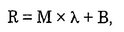
in which R is an approximation formula by a least square method and represents a light reflectance (%), λ represents a wavelength of light (nm),
M represents a wavelength coefficient (%/nm), B represents a constant (%), and R560 represents an estimated reflectance obtained by introducing λ = 560 into the approximation formula R (%). - The white polyester film for a light reflective plate according to claim 1, wherein a gloss level of the side A at an incident angle of 60 degrees is 100% or more.
- The white polyester film for a light reflective plate according to claim 1 or 2, wherein a gloss level of the side (side B) opposite to the side A at an incident angle of 60 degrees is 70% or less.
- A white polyester film for a light reflective plate, wherein the white polyester film has an applied layer containing spherical particles on at least one side of the white polyester film according to claim 1 and an absolute value of a difference in refractive indexes between the spherical particle and a binder resin constituting the applied layer is 0.10 or less.
- The white polyester film for a light reflective plate according to claim 4, wherein said spherical particle is a nonporous resin particle and a coefficient of variation CV of a volume average particle size is 30% or less.
- The white polyester film for a light reflective plate according to claim 5, wherein a resin constituting said spherical particle is at least one selected from the group consisting of acrylic resin, silicone resin, and polystyrene resin, acrylic copolymer, polystyrene copolymer, and copolymer of acrylic vinyl monomer and styrene vinyl monomer.
- The white polyester film for a light reflective plate according to claim 6, wherein said spherical particle contains at least an acrylic resin and said acrylic copolymer is composed of a copolymer of methyl methacrylate and ethylene glycol dimethacrylate.
- The white polyester film for a light reflective plate according to claim 6, wherein said spherical particles are particles having a crosslinking structure.
- The white polyester film for a light reflective plate according to claim 4, wherein said spherical particle contains an ultraviolet absorber and/or a light stabilizer.
- The white polyester film for a light reflective plate according to claim 9, wherein said ultraviolet absorber is at least one of ultraviolet absorbers selected from the group consisting of benzotriazole-based, benzophenone-based, oxalic anilide-based, cyanoacrylate-based and triazine-based ultraviolet absorbers.
- The white polyester film for a light reflective plate according to claim 9, wherein said light stabilizer is a hindered amine-based light stabilizer.
- The white polyester film for a light reflective plate according to claim 4, wherein a resin constituting said spherical particle contains the same monomer components as those of a binder resin constituting said applied layer.
- The white polyester film for a light reflective plate according to claim 1, wherein said white film comprises a three-layer constitution of layer A/layer B/layer A, and the layer B is a layer containing air bubbles, and the layer A is a layer formed by including inorganic particles and/or organic particles in polyester and the content of the particles is 0.5% by weight or less with respect to the total weight of each layer A.
- The white polyester film for a light reflective plate according to claim 1, wherein said white film comprises a three-layer constitution of layer A/layer B/layer A', the layer B is a layer containing air bubbles, and the layer A and/or the layer A' is a layer formed by including inorganic particles and/or organic particles in polyester and the thickness of the layer A' is 0.1 to 3 µm.
- A lamp reflector for a liquid crystal backlight, wherein the white reflective film according to claim 1 is provided with the applied layer face directed to a light source side.
- A direct type liquid crystal backlight, wherein the white reflective film according to claim 1 is provided with the applied layer face directed to a light source side.
Applications Claiming Priority (2)
| Application Number | Priority Date | Filing Date | Title |
|---|---|---|---|
| JP2006292294 | 2006-10-27 | ||
| PCT/JP2007/070582 WO2008053739A1 (en) | 2006-10-27 | 2007-10-23 | White polyester film for light reflective plate |
Publications (2)
| Publication Number | Publication Date |
|---|---|
| EP2077458A1 true EP2077458A1 (en) | 2009-07-08 |
| EP2077458A4 EP2077458A4 (en) | 2012-03-28 |
Family
ID=39344082
Family Applications (1)
| Application Number | Title | Priority Date | Filing Date |
|---|---|---|---|
| EP07830316A Ceased EP2077458A4 (en) | 2006-10-27 | 2007-10-23 | White polyester film for light reflective plate |
Country Status (7)
| Country | Link |
|---|---|
| US (1) | US8227073B2 (en) |
| EP (1) | EP2077458A4 (en) |
| JP (1) | JP5292812B2 (en) |
| KR (1) | KR101398507B1 (en) |
| CN (2) | CN101529281B (en) |
| TW (1) | TWI449967B (en) |
| WO (1) | WO2008053739A1 (en) |
Cited By (1)
| Publication number | Priority date | Publication date | Assignee | Title |
|---|---|---|---|---|
| EP2148227A4 (en) * | 2007-05-08 | 2010-09-01 | Toray Industries | REFLECTIVE FILM WHITE |
Families Citing this family (57)
| Publication number | Priority date | Publication date | Assignee | Title |
|---|---|---|---|---|
| JP5517341B2 (en) * | 2007-12-03 | 2014-06-11 | 株式会社日本触媒 | Polymer particles |
| JP2010026222A (en) * | 2008-07-18 | 2010-02-04 | Jiroo Corporate Plan:Kk | Base sheet for optical sheet |
| JP2010026231A (en) * | 2008-07-18 | 2010-02-04 | Jiroo Corporate Plan:Kk | Optical sheet and backlight unit using the same |
| CN102124380A (en) * | 2008-08-13 | 2011-07-13 | 帝人杜邦薄膜日本有限公司 | Reflective film for lighting equipment |
| JP5369605B2 (en) * | 2008-10-23 | 2013-12-18 | 東レ株式会社 | White reflective film |
| JP5369625B2 (en) * | 2008-11-06 | 2013-12-18 | 東レ株式会社 | White reflective film |
| EP2495284B1 (en) * | 2009-10-28 | 2016-09-28 | Toray Industries, Inc. | Biaxially oriented polyester film |
| CN103467762B (en) * | 2010-02-26 | 2016-01-20 | 东丽株式会社 | The manufacture method of white films |
| WO2011118305A1 (en) * | 2010-03-23 | 2011-09-29 | 東レ株式会社 | White polyester film, light-reflective plate using the same, and liquid-crystal display backlight using the same |
| JP5623892B2 (en) * | 2010-12-10 | 2014-11-12 | 帝人デュポンフィルム株式会社 | Biaxially stretched white polyester film |
| JP5817165B2 (en) * | 2011-03-24 | 2015-11-18 | 東レ株式会社 | White laminated polyester film for reflector and backlight device |
| WO2012132895A1 (en) * | 2011-03-29 | 2012-10-04 | 東レ株式会社 | White-colored reflection film for edge-light type backlight, and liquid crystal display backlight using same |
| US9188731B2 (en) | 2012-05-18 | 2015-11-17 | Reald Inc. | Directional backlight |
| US9235057B2 (en) | 2012-05-18 | 2016-01-12 | Reald Inc. | Polarization recovery in a directional display device |
| US9350980B2 (en) * | 2012-05-18 | 2016-05-24 | Reald Inc. | Crosstalk suppression in a directional backlight |
| US9678267B2 (en) | 2012-05-18 | 2017-06-13 | Reald Spark, Llc | Wide angle imaging directional backlights |
| TWI636283B (en) | 2012-05-18 | 2018-09-21 | 美商瑞爾D斯帕克有限責任公司 | Directional backlight, directional display device and control method thereof |
| BR112015007030B1 (en) | 2012-10-01 | 2022-01-04 | Trinseo Europe Gmbh | COVERED FOR A POINT LIGHT SOURCE AND LIGHT DEVICE |
| JP6087189B2 (en) * | 2013-03-29 | 2017-03-01 | 積水化成品工業株式会社 | Porous resin particles, method for producing the same, and use thereof |
| US9488891B2 (en) * | 2013-04-22 | 2016-11-08 | National University Of Singapore | Thin-surface liquid crystal based voltage sensor |
| KR102272688B1 (en) * | 2013-06-07 | 2021-07-05 | 도레이 카부시키가이샤 | Light-reflective film and edge light-type backlight |
| EP3011734A4 (en) | 2013-06-17 | 2017-02-22 | RealD Inc. | Controlling light sources of a directional backlight |
| JP2014052636A (en) * | 2013-09-10 | 2014-03-20 | Teijin Dupont Films Japan Ltd | Reflective film for liquid crystal display device |
| JP6235287B2 (en) * | 2013-09-30 | 2017-11-22 | 日東電工株式会社 | Optical laminate |
| EP3058562A4 (en) | 2013-10-14 | 2017-07-26 | RealD Spark, LLC | Control of directional display |
| WO2015057588A1 (en) | 2013-10-14 | 2015-04-23 | Reald Inc. | Light input for directional backlight |
| JP6235299B2 (en) * | 2013-10-22 | 2017-11-22 | 帝人フィルムソリューション株式会社 | White reflective film |
| US11067736B2 (en) | 2014-06-26 | 2021-07-20 | Reald Spark, Llc | Directional privacy display |
| US9835792B2 (en) | 2014-10-08 | 2017-12-05 | Reald Spark, Llc | Directional backlight |
| WO2016105541A1 (en) | 2014-12-24 | 2016-06-30 | Reald Inc. | Adjustment of perceived roundness in stereoscopic image of a head |
| RU2596062C1 (en) | 2015-03-20 | 2016-08-27 | Автономная Некоммерческая Образовательная Организация Высшего Профессионального Образования "Сколковский Институт Науки И Технологий" | Method for correction of eye image using machine learning and method of machine learning |
| WO2016168305A1 (en) | 2015-04-13 | 2016-10-20 | Reald Inc. | Wide angle imaging directional backlights |
| US10228505B2 (en) | 2015-05-27 | 2019-03-12 | Reald Spark, Llc | Wide angle imaging directional backlights |
| CN108351951B (en) | 2015-10-26 | 2023-02-07 | 瑞尔D斯帕克有限责任公司 | Intelligent privacy system, equipment and method thereof |
| US10459321B2 (en) | 2015-11-10 | 2019-10-29 | Reald Inc. | Distortion matching polarization conversion systems and methods thereof |
| WO2017083041A1 (en) | 2015-11-13 | 2017-05-18 | Reald Inc. | Wide angle imaging directional backlights |
| US10359561B2 (en) | 2015-11-13 | 2019-07-23 | Reald Spark, Llc | Waveguide comprising surface relief feature and directional backlight, directional display device, and directional display apparatus comprising said waveguide |
| CN108463787B (en) | 2016-01-05 | 2021-11-30 | 瑞尔D斯帕克有限责任公司 | Gaze correction of multi-perspective images |
| CN108699266B (en) * | 2016-02-15 | 2021-07-16 | 株式会社可乐丽 | Thermoplastic resin film, method for producing the same, and laminate |
| US11079619B2 (en) | 2016-05-19 | 2021-08-03 | Reald Spark, Llc | Wide angle imaging directional backlights |
| EP4124795B1 (en) | 2016-05-23 | 2024-04-10 | RealD Spark, LLC | Wide angle imaging directional backlights |
| KR102473525B1 (en) * | 2016-05-31 | 2022-12-02 | 엘지디스플레이 주식회사 | Edge type backlighit unit and display device having the same |
| WO2017217178A1 (en) * | 2016-06-17 | 2017-12-21 | 東レ株式会社 | Resin composition, cured film, method for producing cured film, and display device |
| WO2018129059A1 (en) | 2017-01-04 | 2018-07-12 | Reald Spark, Llc | Optical stack for imaging directional backlights |
| WO2018187154A1 (en) | 2017-04-03 | 2018-10-11 | Reald Spark, Llc | Segmented imaging directional backlights |
| EP4293574A3 (en) | 2017-08-08 | 2024-04-03 | RealD Spark, LLC | Adjusting a digital representation of a head region |
| US11070791B2 (en) | 2017-11-06 | 2021-07-20 | Reald Spark, Llc | Privacy display apparatus |
| EP3743766B1 (en) | 2018-01-25 | 2026-02-11 | RealD Spark, LLC | Touch screen for privacy display |
| KR102078451B1 (en) * | 2018-03-09 | 2020-02-17 | 도레이첨단소재 주식회사 | White polyester film and reflective sheet using the same |
| JP2019164898A (en) * | 2018-03-19 | 2019-09-26 | 三井化学株式会社 | Light guide plate |
| CN108773135A (en) * | 2018-05-04 | 2018-11-09 | 苏州奥美材料科技有限公司 | A kind of high-weatherability makrolon reflective membrane |
| CN112297552A (en) * | 2019-07-31 | 2021-02-02 | 宁波长阳科技股份有限公司 | White reflective polyester film |
| EP4214441A4 (en) | 2020-09-16 | 2024-08-28 | RealD Spark, LLC | VEHICLE EXTERIOR LIGHTING DEVICE |
| CN112485946B (en) * | 2020-12-02 | 2022-11-04 | 合肥乐凯科技产业有限公司 | Reflecting film for thin direct type liquid crystal display device and preparation method thereof |
| US12585094B2 (en) | 2022-06-22 | 2026-03-24 | Reald Spark, Llc | Anamorphic directional illumination device |
| WO2024030274A1 (en) | 2022-08-02 | 2024-02-08 | Reald Spark, Llc | Pupil tracking near-eye display |
| CN119948379A (en) | 2022-08-11 | 2025-05-06 | 瑞尔D斯帕克有限责任公司 | Deformable directional lighting device |
Family Cites Families (35)
| Publication number | Priority date | Publication date | Assignee | Title |
|---|---|---|---|---|
| JPH0816175B2 (en) * | 1991-01-22 | 1996-02-21 | 東レ株式会社 | White polyester film for LCD reflector |
| EP0496323B2 (en) * | 1991-01-22 | 2002-12-11 | Toray Industries, Inc. | Reflector for a surface light source |
| JPH07228611A (en) * | 1994-02-15 | 1995-08-29 | Japan Synthetic Rubber Co Ltd | Polymer emulsion |
| JP3641877B2 (en) * | 1996-05-27 | 2005-04-27 | 東レ株式会社 | White film and method for producing the same |
| US20030108730A1 (en) * | 2000-02-14 | 2003-06-12 | John Francis | Opaque polyester film as substrate with white coatings on both sides |
| GB9617078D0 (en) * | 1996-08-14 | 1996-09-25 | Ici Plc | Polymeric film |
| EP0911152B1 (en) * | 1997-10-24 | 2007-06-20 | Mitsubishi Polyester Film Corporation | White laminated polyester film and imaging medium |
| JPH11320795A (en) | 1998-03-19 | 1999-11-24 | Toray Ind Inc | White composite polyester film |
| US7067188B1 (en) * | 1999-01-21 | 2006-06-27 | Arkema | Polymeric articles having a textured surface and frosted appearance |
| DE19932384A1 (en) * | 1999-07-14 | 2001-01-18 | Mitsubishi Polyester Film Gmbh | White, biaxially oriented polyester film with cycloolefin copolymer (COC), process for its production and its use |
| JP2001209038A (en) * | 1999-11-17 | 2001-08-03 | Nippon Sheet Glass Co Ltd | Substrate for liquid crystal display element |
| JP2001166295A (en) | 1999-12-03 | 2001-06-22 | Cosmo Tec:Kk | Lamp reflector for LCD backlight |
| JP4501042B2 (en) * | 1999-12-21 | 2010-07-14 | 東洋紡績株式会社 | White polyester film laminate |
| JP2001200129A (en) * | 2000-01-18 | 2001-07-24 | Jsr Corp | Composite particle, dispersion thereof, method for producing dispersion, and coating material |
| DE10009246A1 (en) * | 2000-02-28 | 2001-08-30 | Mitsubishi Polyester Film Gmbh | White, biaxially oriented and UV-stabilized polyester film with cycloolefinocopolymer (COC), process for its production and its use |
| DE10009295A1 (en) * | 2000-02-28 | 2001-08-30 | Mitsubishi Polyester Film Gmbh | White, biaxially oriented, flame-retardant polyester film with cycloolefin copolymer, process for its production and its use |
| DE10022942A1 (en) * | 2000-05-11 | 2001-11-15 | Mitsubishi Polyester Film Gmbh | Mat white biaxially oriented polyester film, e.g. useful for food packaging, includes a cycloolefin copolymer |
| JP4573946B2 (en) | 2000-05-16 | 2010-11-04 | 株式会社きもと | Light diffusing sheet |
| JP3870731B2 (en) | 2000-07-12 | 2007-01-24 | 東レ株式会社 | White film for surface light source reflector |
| TWI235866B (en) * | 2000-12-14 | 2005-07-11 | Mitsui Chemicals Inc | Reflector, sidelight type backlighting apparatus and reflector substrate |
| JP4945032B2 (en) | 2001-05-08 | 2012-06-06 | 恵和株式会社 | Reflective sheet and backlight unit using the same |
| JP4766805B2 (en) * | 2001-09-20 | 2011-09-07 | 恵和株式会社 | Reflective sheet and backlight unit using the same |
| JP2003160682A (en) | 2001-11-27 | 2003-06-03 | Toray Ind Inc | Light reflective film |
| US20030128313A1 (en) * | 2001-12-14 | 2003-07-10 | Eastman Kodak Company | Light diffusion material with color temperature correction |
| US7224527B2 (en) * | 2003-02-21 | 2007-05-29 | Mitsui Chemicals, Inc. | Reflector and application thereof |
| KR100553655B1 (en) * | 2003-03-12 | 2006-02-24 | 도레이새한 주식회사 | Microporous Polyester Film |
| CN1781035A (en) * | 2003-04-28 | 2006-05-31 | 三菱树脂株式会社 | Reflector for liquid crystal display, manufacturing method thereof, and backlight assembly |
| EP1635196A4 (en) * | 2003-06-17 | 2008-10-01 | Teijin Chemicals Ltd | DIRECT BACKLIGHT LIQUID CRYSTAL DISPLAY AND LIGHT DIFFUSION PLATE |
| JP3946183B2 (en) * | 2003-10-27 | 2007-07-18 | 帝人デュポンフィルム株式会社 | White polyester film |
| JP2005173546A (en) * | 2003-11-18 | 2005-06-30 | Toray Ind Inc | Light reflecting film and surface light source using the same |
| JP4933060B2 (en) * | 2004-05-31 | 2012-05-16 | 株式会社ユポ・コーポレーション | Light reflector and surface light source device using the same |
| KR101123479B1 (en) * | 2004-05-31 | 2012-03-28 | 가부시키가이샤 유포 코포레숀 | Light reflector and planar light source device |
| JP2006095944A (en) * | 2004-09-30 | 2006-04-13 | Furukawa Electric Co Ltd:The | Thermoplastic resin foam |
| DE502006001168D1 (en) * | 2005-06-01 | 2008-09-04 | Mitsubishi Polyester Film Gmbh | White opaque film with low transparency and improved dielectric strength |
| KR100716144B1 (en) * | 2005-10-21 | 2007-05-10 | 도레이새한 주식회사 | Diffusion Sheet for Thin Film Transistor Liquid Crystal Display |
-
2007
- 2007-10-23 EP EP07830316A patent/EP2077458A4/en not_active Ceased
- 2007-10-23 WO PCT/JP2007/070582 patent/WO2008053739A1/en not_active Ceased
- 2007-10-23 JP JP2007558374A patent/JP5292812B2/en not_active Expired - Fee Related
- 2007-10-23 US US12/446,605 patent/US8227073B2/en active Active
- 2007-10-23 CN CN2007800400888A patent/CN101529281B/en active Active
- 2007-10-23 CN CN2011101993997A patent/CN102269831B/en not_active Expired - Fee Related
- 2007-10-23 KR KR1020097007340A patent/KR101398507B1/en not_active Expired - Fee Related
- 2007-10-26 TW TW96140182A patent/TWI449967B/en not_active IP Right Cessation
Cited By (2)
| Publication number | Priority date | Publication date | Assignee | Title |
|---|---|---|---|---|
| EP2148227A4 (en) * | 2007-05-08 | 2010-09-01 | Toray Industries | REFLECTIVE FILM WHITE |
| US8300172B2 (en) | 2007-05-08 | 2012-10-30 | Toray Industries, Inc. | White reflective film |
Also Published As
| Publication number | Publication date |
|---|---|
| CN101529281A (en) | 2009-09-09 |
| KR20090073148A (en) | 2009-07-02 |
| US8227073B2 (en) | 2012-07-24 |
| WO2008053739A1 (en) | 2008-05-08 |
| EP2077458A4 (en) | 2012-03-28 |
| TW200829962A (en) | 2008-07-16 |
| KR101398507B1 (en) | 2014-06-27 |
| JPWO2008053739A1 (en) | 2010-02-25 |
| CN102269831A (en) | 2011-12-07 |
| TWI449967B (en) | 2014-08-21 |
| US20100034987A1 (en) | 2010-02-11 |
| CN101529281B (en) | 2011-09-07 |
| JP5292812B2 (en) | 2013-09-18 |
| CN102269831B (en) | 2013-09-18 |
Similar Documents
| Publication | Publication Date | Title |
|---|---|---|
| US8227073B2 (en) | White polyester film for light reflective plate | |
| TWI515393B (en) | White reflective film | |
| JP4889055B2 (en) | White reflective film | |
| CN102782532B (en) | White polyester film, light-reflective plate using the same, and liquid-crystal display backlight using the same | |
| CN103080784B (en) | Process for producing white layered film, and white layered polyester film | |
| JP5098834B2 (en) | White reflective film | |
| CN101375185B (en) | Film for surface light source reflection member | |
| JP5532799B2 (en) | White reflective film | |
| TWI459045B (en) | White reflective film | |
| JP5817165B2 (en) | White laminated polyester film for reflector and backlight device | |
| JP2008286907A (en) | Reflective laminate | |
| JP2007072429A (en) | White polyester film for LCD display reflector |
Legal Events
| Date | Code | Title | Description |
|---|---|---|---|
| PUAI | Public reference made under article 153(3) epc to a published international application that has entered the european phase |
Free format text: ORIGINAL CODE: 0009012 |
|
| 17P | Request for examination filed |
Effective date: 20090423 |
|
| AK | Designated contracting states |
Kind code of ref document: A1 Designated state(s): AT BE BG CH CY CZ DE DK EE ES FI FR GB GR HU IE IS IT LI LT LU LV MC MT NL PL PT RO SE SI SK TR |
|
| RIN1 | Information on inventor provided before grant (corrected) |
Inventor name: FUJII, HIDEKI Inventor name: OKUDA, MASAHIRO Inventor name: TANAKA, KAZUNORI |
|
| A4 | Supplementary search report drawn up and despatched |
Effective date: 20120229 |
|
| RIC1 | Information provided on ipc code assigned before grant |
Ipc: G02B 5/08 20060101AFI20120223BHEP Ipc: B32B 27/36 20060101ALI20120223BHEP Ipc: C08J 5/18 20060101ALI20120223BHEP Ipc: C08J 7/04 20060101ALI20120223BHEP Ipc: G02F 1/1335 20060101ALI20120223BHEP |
|
| DAX | Request for extension of the european patent (deleted) | ||
| 17Q | First examination report despatched |
Effective date: 20120927 |
|
| REG | Reference to a national code |
Ref country code: DE Ref legal event code: R003 |
|
| STAA | Information on the status of an ep patent application or granted ep patent |
Free format text: STATUS: THE APPLICATION HAS BEEN REFUSED |
|
| 18R | Application refused |
Effective date: 20141211 |