EP2077241A2 - Container with lid - Google Patents
Container with lid Download PDFInfo
- Publication number
- EP2077241A2 EP2077241A2 EP08172764A EP08172764A EP2077241A2 EP 2077241 A2 EP2077241 A2 EP 2077241A2 EP 08172764 A EP08172764 A EP 08172764A EP 08172764 A EP08172764 A EP 08172764A EP 2077241 A2 EP2077241 A2 EP 2077241A2
- Authority
- EP
- European Patent Office
- Prior art keywords
- container
- lid
- wall
- projection
- rib
- Prior art date
- Legal status (The legal status is an assumption and is not a legal conclusion. Google has not performed a legal analysis and makes no representation as to the accuracy of the status listed.)
- Withdrawn
Links
Images




Classifications
-
- B—PERFORMING OPERATIONS; TRANSPORTING
- B65—CONVEYING; PACKING; STORING; HANDLING THIN OR FILAMENTARY MATERIAL
- B65F—GATHERING OR REMOVAL OF DOMESTIC OR LIKE REFUSE
- B65F1/00—Refuse receptacles; Accessories therefor
- B65F1/14—Other constructional features; Accessories
- B65F1/16—Lids or covers
-
- B—PERFORMING OPERATIONS; TRANSPORTING
- B65—CONVEYING; PACKING; STORING; HANDLING THIN OR FILAMENTARY MATERIAL
- B65D—CONTAINERS FOR STORAGE OR TRANSPORT OF ARTICLES OR MATERIALS, e.g. BAGS, BARRELS, BOTTLES, BOXES, CANS, CARTONS, CRATES, DRUMS, JARS, TANKS, HOPPERS, FORWARDING CONTAINERS; ACCESSORIES, CLOSURES, OR FITTINGS THEREFOR; PACKAGING ELEMENTS; PACKAGES
- B65D43/00—Lids or covers for rigid or semi-rigid containers
- B65D43/14—Non-removable lids or covers
- B65D43/16—Non-removable lids or covers hinged for upward or downward movement
- B65D43/163—Non-removable lids or covers hinged for upward or downward movement the container and the lid being made separately
- B65D43/164—Non-removable lids or covers hinged for upward or downward movement the container and the lid being made separately and connected by interfitting hinge elements integrally with the container and the lid formed respectively
-
- B—PERFORMING OPERATIONS; TRANSPORTING
- B65—CONVEYING; PACKING; STORING; HANDLING THIN OR FILAMENTARY MATERIAL
- B65D—CONTAINERS FOR STORAGE OR TRANSPORT OF ARTICLES OR MATERIALS, e.g. BAGS, BARRELS, BOTTLES, BOXES, CANS, CARTONS, CRATES, DRUMS, JARS, TANKS, HOPPERS, FORWARDING CONTAINERS; ACCESSORIES, CLOSURES, OR FITTINGS THEREFOR; PACKAGING ELEMENTS; PACKAGES
- B65D2251/00—Details relating to container closures
- B65D2251/10—Details of hinged closures
- B65D2251/1083—Closures formed of several sections hinged to the container or base
Definitions
- the present invention relates generally to containers, and more particularly to containers with attached lids.
- Containers with attached lids are used for many purposes. These containers generally include a pair of opposing side walls and a pair of opposing end walls integrally molded with a base. Typically a pair of lids are each hingeably connected to one of the side walls. The lids include a plurality of tongues that interlock in the middle of the container in the closed position.
- the container After being emptied, the container must be washed prior to reuse.
- the container In order to wash the container, the container is inverted on a conveyor with the lids open.
- the lids In order to prevent water from accumulating on the upper surfaces of the open lids, the lids may be tied up at an angle.
- the container may also be tipped onto its side by another conveyor to further assist in the drainage.
- a container includes a base and a plurality of sidewalls. At least one lid is pivotably connected to one of the walls. The lid includes at least one projection that contacts at least one rib on the exterior surface of the wall when the lid is pivoted to an open position. This prevents over-rotation of the lid, such as when the lid and container are resting on the wall of the autoclave prior to dumping.
- the lid includes at least one projection from an interior surface of the lid proximate the axis.
- the at least one projection contacts the support surface thereby pivoting the lid to a position where it is not parallel to the floor, thus ensuring that water drains from the lid during washing.
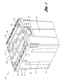
- a container 10 according to one embodiment of the present invention is shown in Figure 1 .
- the container 10 includes a base 12 integrally molded with opposing side walls 14 and opposing end walls 16.
- a lip 20 protrudes outwardly and downwardly from a periphery of the upper edges of the side walls 14 and end walls 16.
- the side walls 14 each include a pair of outer ribs 21 and inner ribs 22 extending vertically on an exterior surface of the side wall 14.
- the outer ribs 21 extend downwardly from the lip 20 further than the inner ribs 22.
- the outer ribs 21 are also a little deeper than the inner ribs 22.
- the end walls 16 each include an integrally molded handle 26 defining a hand opening 28 between the handle 26 and the end walls 16. Ribs 30 are formed in the handle 26 and face upwardly.
- the container 10 includes a pair of lids 34, each connected to an uppermost edge of one of the side walls 14 by a hinge 36.
- Each of the lids 34 includes an outer reinforcement portion 40 and an inner reinforcement portion 41. Both reinforcement portions 40, 41 are elongated in a direction generally parallel to an axis of the hinge 36.
- the outer reinforcement portions 40 are shorter than the inner reinforcement portions 41 in a longitudinal direction.
- the outer reinforcement portions 40 each include an interlocking portion 42 at each end, projecting upwardly further than the outer reinforcement portion 40.
- Each lid 34 also includes a latch portion 46 for latching to the lip 20.
- the lids 34 further include interleaved tongues 48, as is known in the art.
- Figure 2 is a top view of the container 10. As can be seen in Figure 2 , the handle 26 projects outwardly from the footprint of the container 10.
- Figure 3 is an end view of the container 10.
- Figure 4 is a side view of the container 10. Again, it can be seen that the handles 26 project outwardly of the footprint of the container 10 and outwardly of the lip 20.
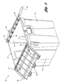
- FIG 5 is perspective view of the container 10 with the lids 34 open.
- Each of the lids 34 includes a pair of projections 50 projecting downwardly from an interior surface of the lid 34.
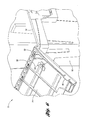
- Figure 6 is an enlarged view showing one of the projections 50 on the interior surface of the lid 34, proximate the hinge 36.
- the projections 50 are positioned proximate the hinges 36.
- the projections 50 are positioned much closer to the hinge 36 than the opposite edge of the lid 34.
- the distance between the axis of the hinge 36 and the projections 50 is less than a tenth of the distance between the axis of the hinge 36 and an opposite edge of the lid 34.
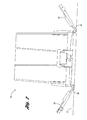
- FIG 7 is an end view of the container 10 inverted, with the lids 34 open and resting on a support surface S, which could be a floor or conveyor.
- a support surface S which could be a floor or conveyor.
- the projections 50 contact the support surface S and cause the lids 34 to pivot upwardly as shown.
- the container 10 is supported solely on the projections 50, such that the weight of the container is used to pivot the lids 34 to this drainage position.
- the lids 34 are approximately thirty degrees relative to the support surface S.
- the lid 34 is automatically in pivoted to a drainage position for washing. This will prevent water from accumulating on the exterior surface of the lids 34.
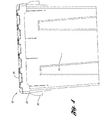
- Figure 9 is a section view through one of the side walls 14 and lids 34 in the open position.
- the outer reinforcement portion 40 contacts the inner ribs 22 on the side wall 14, while the inner reinforcement portions 41 contact the outer ribs 21 on the side wall 14.
- the outer reinforcement portions 40 do not contact the outer ribs 21, because they are too short.
- the weight of the container 10 would be born by the ribs 21, 22 via the lid 34, and not solely by the hinge 36 as in the prior art.
Landscapes
- Engineering & Computer Science (AREA)
- Mechanical Engineering (AREA)
- Closures For Containers (AREA)
- Cookers (AREA)
Abstract
Description
- The present invention relates generally to containers, and more particularly to containers with attached lids.
- Containers with attached lids are used for many purposes. These containers generally include a pair of opposing side walls and a pair of opposing end walls integrally molded with a base. Typically a pair of lids are each hingeably connected to one of the side walls. The lids include a plurality of tongues that interlock in the middle of the container in the closed position.
- One use for this type of containers is for medical waste. Medical waste is placed in the container, which is then closed and shipped to a biohazard facility for disposal. At the facility, the contents of the container are dumped into an autoclave for disposal. During dumping, one of the lids is open and pivoted outward until it abuts its respective side wall. The container is then tipped, with the lid resting on a wall of the autoclave, and the container is inverted to dump the contents into the autoclave. This sometimes breaks the lid and/or the hinge connecting the lid to the side wall.
- After being emptied, the container must be washed prior to reuse. In order to wash the container, the container is inverted on a conveyor with the lids open. In order to prevent water from accumulating on the upper surfaces of the open lids, the lids may be tied up at an angle. The container may also be tipped onto its side by another conveyor to further assist in the drainage.
- It is desirable to provide an improved such container which addresses the above described problems and/or which more generally offers improvements or an alternative to existing arrangements.
- According to the present invention there is therefore provided a container as described in the accompanying claims.
- A container according to one embodiment of the present invention includes a base and a plurality of sidewalls. At least one lid is pivotably connected to one of the walls. The lid includes at least one projection that contacts at least one rib on the exterior surface of the wall when the lid is pivoted to an open position. This prevents over-rotation of the lid, such as when the lid and container are resting on the wall of the autoclave prior to dumping.
- In a second feature of the present invention, the lid includes at least one projection from an interior surface of the lid proximate the axis. When the container is inverted with the lid open for washing, the at least one projection contacts the support surface thereby pivoting the lid to a position where it is not parallel to the floor, thus ensuring that water drains from the lid during washing.
- These and other features of the application can be best understood from the following specification and drawings, the following of which is a brief description, and in which:
-
Figure 1 is a perspective view of a container according to one embodiment of the present invention; -
Figure 2 is a top view of the container ofFigure 1 ; -
Figure 3 is an end view of the container ofFigure 1 ; -
Figure 4 is a side view of the container ofFigure 1 ; -
Figure 5 is a perspective view of the container ofFigure 1 with the lids in the open position; -
Figure 6 is an enlarged perspective view of the container ofFigure 5 ; -
Figure 7 is an end view of the container ofFigure 1 in an inverted position with the lids open on a support surface; -
Figure 8 is an enlarged view of the hinge area of the container ofFigure 1 ; and -
Figure 9 is a section view through one of the side walls and one of the lids in the open position. - A
container 10 according to one embodiment of the present invention is shown inFigure 1 . Thecontainer 10 includes abase 12 integrally molded withopposing side walls 14 and opposingend walls 16. Alip 20 protrudes outwardly and downwardly from a periphery of the upper edges of theside walls 14 andend walls 16. Theside walls 14 each include a pair ofouter ribs 21 andinner ribs 22 extending vertically on an exterior surface of theside wall 14. Theouter ribs 21 extend downwardly from thelip 20 further than theinner ribs 22. Theouter ribs 21 are also a little deeper than theinner ribs 22. - The
end walls 16 each include an integrally moldedhandle 26 defining a hand opening 28 between thehandle 26 and theend walls 16.Ribs 30 are formed in thehandle 26 and face upwardly. - The
container 10 includes a pair oflids 34, each connected to an uppermost edge of one of theside walls 14 by ahinge 36. Each of thelids 34 includes anouter reinforcement portion 40 and aninner reinforcement portion 41. Bothreinforcement portions hinge 36. Theouter reinforcement portions 40 are shorter than theinner reinforcement portions 41 in a longitudinal direction. Theouter reinforcement portions 40 each include an interlockingportion 42 at each end, projecting upwardly further than theouter reinforcement portion 40. Eachlid 34 also includes alatch portion 46 for latching to thelip 20. Thelids 34 further include interleavedtongues 48, as is known in the art. -
Figure 2 is a top view of thecontainer 10. As can be seen inFigure 2 , thehandle 26 projects outwardly from the footprint of thecontainer 10. -
Figure 3 is an end view of thecontainer 10.Figure 4 is a side view of thecontainer 10. Again, it can be seen that thehandles 26 project outwardly of the footprint of thecontainer 10 and outwardly of thelip 20. -
Figure 5 is perspective view of thecontainer 10 with thelids 34 open. Each of thelids 34 includes a pair ofprojections 50 projecting downwardly from an interior surface of thelid 34.Figure 6 is an enlarged view showing one of theprojections 50 on the interior surface of thelid 34, proximate thehinge 36. Theprojections 50 are positioned proximate thehinges 36. In this particular example, theprojections 50 are positioned much closer to thehinge 36 than the opposite edge of thelid 34. In the example shown, the distance between the axis of thehinge 36 and theprojections 50 is less than a tenth of the distance between the axis of thehinge 36 and an opposite edge of thelid 34. -
Figure 7 is an end view of thecontainer 10 inverted, with thelids 34 open and resting on a support surface S, which could be a floor or conveyor. As can be seen more clearly inFigure 8 , in this position, theprojections 50 contact the support surface S and cause thelids 34 to pivot upwardly as shown. Preferably, thecontainer 10 is supported solely on theprojections 50, such that the weight of the container is used to pivot thelids 34 to this drainage position. In the drainage position, thelids 34 are approximately thirty degrees relative to the support surface S. Thus, without any ties, bands or hooks, thelid 34 is automatically in pivoted to a drainage position for washing. This will prevent water from accumulating on the exterior surface of thelids 34. -
Figure 9 is a section view through one of theside walls 14 andlids 34 in the open position. When opened all the way, as shown, theouter reinforcement portion 40 contacts theinner ribs 22 on theside wall 14, while theinner reinforcement portions 41 contact theouter ribs 21 on theside wall 14. Theouter reinforcement portions 40 do not contact theouter ribs 21, because they are too short. Thus, if thecontainer 10 were tipped and rested on thelid 34 shown inFigure 9 , the weight of thecontainer 10 would be born by theribs lid 34, and not solely by thehinge 36 as in the prior art. - It should be noted that variations could be utilized, including various arrangements of the
reinforcement portions ribs lids 34 could also be utilized within the scope of this invention. - In accordance with the provisions of the patent statutes and jurisprudence, exemplary configurations described above are considered to represent a preferred embodiment of the invention. However, it should be noted that the invention can be practiced otherwise than as specifically illustrated and described without departing from its spirit or scope.
Claims (15)
- A container (10) comprising:a base (12);a plurality of walls (14,16) extending upward from the base (12), the plurality of walls (14,16) including a first wall (14); anda lid (34) connected to the first wall (14) and pivotable relative to the first wall (14) about an axis between an open position and a closed position, the lid (34) including a at least one projection (50) projecting from an interior surface of the lid (34) proximate the axis, wherein the at least one projection (50) pivots the lid (34) to a drain position not parallel to a support surface (S) when the container (10) is placed inverted on the support surface (S).
- The container (10) of claim 1 wherein the lid (34) is pivoted by the at least one projection (5) to an angle approximately thirty degrees relative to the support surface (S) when the container (10) is placed inverted on the support surface (S).
- The container (10) of claim 1 or 2 wherein the at least one projection (50) is positioned much closer to the axis than to an edge of the lid (34) opposite the axis.
- The container (10) of claim 3 wherein the at least one projection (5) is positioned at a distance from the axis less than approximately 1/10th a distance from the axis to an edge of the lid (34) opposite the axis.
- The container (10) of any preceding claim wherein the lid (34) is pivotably connected to the first wall (14) about said axis by a hinge (36).
- The container (10) of any preceding claim wherein the lid (34) is a first lid (34), the container (10) further including a second lid (34) pivotably attached to a second wall (14) of the plurality of walls (14,16), the second wall (14) opposite the first wall (14), the second lid (34) including at least one second projection (50) extending from an interior surface of the second lid (34), wherein the at least one second projection (50) pivots the second lid (34) to a drain position not parallel to the support surface (S) when the container (10) is placed inverted on the support surface (S).
- The container (10) of claim 6 wherein the container (10) rests on the first lid (34) and the second lid (34) on the support surface (S) when the container (10) is in the inverted position on the support surface (S).
- A container (10) comprising:a base (12);a plurality of walls (14,16) extending upward from the base (12), the plurality of walls (14,16) including a first wall (14), the first wall (14) including at least one rib (21, 22) on an exterior surface; anda lid (34) pivotably connected to the first wall (14), the lid (34) including at least one projection (40,41) projecting upwardly, the lid (34) pivotable to an open position where the at least one projection (40,41) contacts the at least one rib (21,22) to prevent over-rotation of the lid (34).
- The container (10) of claim 8 wherein the at least one projection (40,41) includes a first reinforced portion (41) that is elongated generally parallel to an axis about which the lid (34) is pivotably connected to the first wall (34).
- The container (10) of claim 9 wherein the lid (34) is connected to the first wall (14) by a hinge (36) and wherein the at least one projection (40,41) further includes a second reinforced portion (40).
- The container (10) of claim 10 wherein the second reinforced portion (40) is between the first reinforced portion (41) and the hinge (36).
- The container (10) of claim 11 wherein the second reinforced portion (40) is elongated generally parallel to the axis.
- The container (10) of claim 11 or 12 wherein the at least one rib (21,22) includes a first rib (21) and a second rib (22) and wherein the first reinforced portion (41) contacts the first rib (21) in the open position and the second reinforced portion (40) contacts the second rib (22) in the open position.
- The container (10) of claim 13 wherein the second reinforced portion (40) does not contact the first rib (22) in the open position.
- The container (10) of claim 13 or 14 wherein the first rib (21) is lower on the first wall (14) than the second rib (22).
Applications Claiming Priority (1)
| Application Number | Priority Date | Filing Date | Title |
|---|---|---|---|
| US11/968,906 US20090173744A1 (en) | 2008-01-03 | 2008-01-03 | Container with lid |
Publications (2)
| Publication Number | Publication Date |
|---|---|
| EP2077241A2 true EP2077241A2 (en) | 2009-07-08 |
| EP2077241A3 EP2077241A3 (en) | 2012-01-25 |
Family
ID=40352115
Family Applications (1)
| Application Number | Title | Priority Date | Filing Date |
|---|---|---|---|
| EP08172764A Withdrawn EP2077241A3 (en) | 2008-01-03 | 2008-12-23 | Container with lid |
Country Status (4)
| Country | Link |
|---|---|
| US (1) | US20090173744A1 (en) |
| EP (1) | EP2077241A3 (en) |
| CA (1) | CA2647659A1 (en) |
| MX (1) | MX2008014937A (en) |
Cited By (1)
| Publication number | Priority date | Publication date | Assignee | Title |
|---|---|---|---|---|
| EP3486197A1 (en) * | 2017-11-15 | 2019-05-22 | ESE World B.V. | Lid device for a refuse receptacle |
Families Citing this family (34)
| Publication number | Priority date | Publication date | Assignee | Title |
|---|---|---|---|---|
| US9926112B2 (en) * | 2011-04-25 | 2018-03-27 | Daniel Greenberg | Containment system and adaptive sealing systems therefore with collapsible feature and methods for operating the same |
| US8998031B2 (en) | 2011-08-26 | 2015-04-07 | Stericycle, Inc. | Waste container assembly |
| CN104029955B (en) * | 2013-03-08 | 2017-12-05 | 倪国森 | Intercept type linkage tipping bucket is classified garbage box monitored |
| CN104370029B (en) * | 2013-08-12 | 2018-02-13 | 倪国森 | Weighing type community classified-refuse recovery system |
| GB201400437D0 (en) | 2014-01-10 | 2014-02-26 | Loadhog Ltd | Container |
| CN104291005B (en) * | 2014-09-26 | 2017-05-24 | 青岛冠宇工业设备有限公司 | Waterproof circulation box |
| USD873020S1 (en) | 2017-06-12 | 2020-01-21 | Yeti Coolers, Llc | Container |
| USD828028S1 (en) | 2017-06-12 | 2018-09-11 | Yeti Coolers, Llc | Container |
| USD838983S1 (en) | 2017-06-12 | 2019-01-29 | Yeti Coolers, Llc | Container |
| USD869160S1 (en) | 2017-06-12 | 2019-12-10 | Yeti Coolers, Llc | Container |
| USD872478S1 (en) | 2017-06-12 | 2020-01-14 | Yeti Coolers, Llc | Container |
| USD828029S1 (en) | 2017-06-12 | 2018-09-11 | Yeti Coolers, Llc | Container |
| EP3638598B1 (en) | 2017-06-12 | 2023-01-18 | Yeti Coolers, LLC | Container and latching system |
| USD838984S1 (en) | 2017-06-12 | 2019-01-29 | Yeti Coolers, Llc | Container |
| US11976498B2 (en) | 2017-06-12 | 2024-05-07 | Yeti Coolers, Llc | Container and latching system |
| US11685573B2 (en) | 2017-06-12 | 2023-06-27 | Yeti Coolers, Llc | Carry strap for container |
| USD840150S1 (en) | 2017-06-12 | 2019-02-12 | Yeti Coolers, Llc | Container |
| US12108853B2 (en) | 2019-01-06 | 2024-10-08 | Yeti Coolers, Llc | Luggage system |
| USD872485S1 (en) | 2017-06-12 | 2020-01-14 | Yeti Coolers, Llc | Container |
| CA178734S (en) | 2017-06-12 | 2019-05-31 | Yeti Coolers Llc | Container |
| KR200491148Y1 (en) * | 2018-10-05 | 2020-02-27 | 김돈일 | Split Plate Installment Structure of Container for Medical Waste |
| USD907445S1 (en) | 2018-12-11 | 2021-01-12 | Yeti Coolers, Llc | Container accessories |
| USD904829S1 (en) | 2018-12-11 | 2020-12-15 | Yeti Coolers, Llc | Container accessories |
| US12225993B2 (en) | 2019-01-06 | 2025-02-18 | Yeti Coolers, Llc | Luggage system |
| CN113271806A (en) | 2019-01-06 | 2021-08-17 | 野醍冷却器有限责任公司 | Luggage system |
| CH716398A1 (en) | 2019-07-11 | 2021-01-15 | Utz Georg Holding Ag | Container with lockable lid. |
| USD955106S1 (en) | 2019-09-20 | 2022-06-21 | L&F Plastics, Co., Ltd. | Container |
| USD951643S1 (en) | 2020-06-30 | 2022-05-17 | Yeti Coolers, Llc | Luggage |
| USD961926S1 (en) | 2020-06-30 | 2022-08-30 | Yeti Coolers, Llc | Luggage |
| USD963344S1 (en) | 2020-06-30 | 2022-09-13 | Yeti Coolers, Llc | Luggage |
| USD954436S1 (en) | 2020-06-30 | 2022-06-14 | Yeti Coolers, Llc | Luggage |
| USD960648S1 (en) | 2020-12-16 | 2022-08-16 | Yeti Coolers, Llc | Container accessory |
| USD994438S1 (en) | 2020-12-16 | 2023-08-08 | Yeti Coolers, Llc | Container |
| USD985937S1 (en) | 2020-12-16 | 2023-05-16 | Yeti Coolers, Llc | Container |
Family Cites Families (56)
| Publication number | Priority date | Publication date | Assignee | Title |
|---|---|---|---|---|
| US1026649A (en) * | 1911-10-06 | 1912-05-21 | Hiram Beshore | Safe. |
| US1047343A (en) * | 1912-04-01 | 1912-12-17 | Bryan M Vaughn | Sample-case. |
| US1178773A (en) * | 1914-07-08 | 1916-04-11 | Milton O Adams | Metallic structure for the tops of receptacles. |
| US1547662A (en) * | 1923-06-04 | 1925-07-28 | Miniere Salvatore | Receptacle |
| US1742075A (en) * | 1927-07-25 | 1929-12-31 | Houghten Roy | Receptacle for refuse |
| US2275373A (en) * | 1940-01-31 | 1942-03-03 | Lois B Crown | Document case |
| US2505898A (en) * | 1947-02-26 | 1950-05-02 | Hyman A Jaffe | Portable picnic chest having detachable table top |
| US3463345A (en) * | 1968-08-28 | 1969-08-26 | Ms Ind Inc | Lidded tote box |
| USD252596S (en) * | 1977-02-18 | 1979-08-14 | Emy Adler | Purse insert |
| US4161261A (en) * | 1978-05-05 | 1979-07-17 | Menasha Corporation | Security container |
| US4154362A (en) * | 1978-05-12 | 1979-05-15 | Curtiscorp, Inc. | Self-attaching hinge for polystyrene containers and latch means integral therewith |
| US4364489A (en) * | 1980-04-28 | 1982-12-21 | Nestier Canada Inc. | Container lid |
| US4620644A (en) * | 1981-03-27 | 1986-11-04 | Buckhorn Material Handling Group Inc. | Tote box with lid container |
| US4432467A (en) * | 1982-03-08 | 1984-02-21 | Menasha Corporation | Reinforced lid construction for security containers or the like |
| US4523692A (en) * | 1983-06-30 | 1985-06-18 | Jack Lemkin | Reversible security cover for stackable and nestable tote box |
| USRE33384E (en) * | 1985-02-27 | 1990-10-16 | Buckhorn, Inc. | Nesting box with reduced lid flares |
| US4688675A (en) * | 1985-02-27 | 1987-08-25 | Buckhorn Material Handling Group, Inc. | Nesting box with reduced lid flares |
| US4572368A (en) * | 1985-07-18 | 1986-02-25 | Buckhorn Material Handling Group, Inc. | Tote box |
| GB2192666B (en) * | 1986-07-15 | 1989-12-13 | Perstorp Ab | Improvements in or relating to a nestable-stackable container |
| US4685567A (en) * | 1986-11-13 | 1987-08-11 | Peninsula Plastics Company, Inc. | Nestable, stackable tote boxes |
| US4741433A (en) * | 1987-03-10 | 1988-05-03 | Idmd Inc. | Child resistant box |
| US4765480A (en) * | 1987-08-03 | 1988-08-23 | Xytec Plastics, Inc. | Container with collapsible lid members |
| USD319904S (en) * | 1988-08-25 | 1991-09-10 | Cozzi Andrew M | Container for recycling |
| US4892221A (en) * | 1988-12-06 | 1990-01-09 | Menasha Corporation | Detachable lid container |
| US4944422A (en) * | 1989-11-29 | 1990-07-31 | Aurness Harold O | Expandable home package delivery box |
| US5051725A (en) * | 1990-06-18 | 1991-09-24 | Soa Systems, Inc. | Security container |
| US5294413A (en) * | 1991-07-17 | 1994-03-15 | Hu-Friedy Mfg. Co., Inc. | Sterilization and storage cassette |
| US5250981A (en) * | 1992-08-13 | 1993-10-05 | Xerox Corporation | Copier or scanner platen cover documents retainer |
| US5328048A (en) * | 1993-02-08 | 1994-07-12 | Otto Industries, Inc. | Tote box |
| DE4310392A1 (en) * | 1993-03-30 | 1994-10-06 | Schaefer Gmbh Fritz | Nestable transport container |
| US5330069A (en) * | 1993-04-12 | 1994-07-19 | Buckhorn Material Handling Group, Inc. | Bi-fold lid for container |
| CA2095095A1 (en) * | 1993-04-28 | 1994-10-29 | Michel Lanoue | Plastic container with hinged lids |
| US5555996A (en) * | 1993-08-06 | 1996-09-17 | Rehrig Pacific Company | Bag-in box with split lid |
| US5474200A (en) * | 1994-05-06 | 1995-12-12 | Otto Industries, Inc. | Lidded container having security hinge |
| US5673791A (en) * | 1994-10-04 | 1997-10-07 | Buckhorn Material Handling Group, Inc. | Container and lid for container |
| US5967322A (en) * | 1995-02-02 | 1999-10-19 | Rehrig Pacific Company, Inc. | Container assembly with tamper evident seal |
| US5524750A (en) * | 1995-08-04 | 1996-06-11 | Buckhorn Material Handling Group, Inc. | Card holder for container |
| GB9613632D0 (en) * | 1996-06-28 | 1996-08-28 | Mckechnie Uk Ltd | Container |
| US5678693A (en) * | 1996-07-26 | 1997-10-21 | Dale Tapp | Glass storage safe |
| US5832543A (en) * | 1996-08-09 | 1998-11-10 | Bossmere Products, Inc. | Portable pocket spittoon |
| US5860527A (en) * | 1996-10-18 | 1999-01-19 | Menasha Corporation | Plastic tote box improvements |
| US6000576A (en) * | 1998-07-10 | 1999-12-14 | Liu; Ching-Rong | Structure for covered storage bins |
| US6318586B1 (en) * | 1998-12-18 | 2001-11-20 | Menasha Corporation | Plastic tote box improvements |
| GB2345053B (en) * | 1998-12-23 | 2003-01-29 | Mckechnie | Container |
| US6041931A (en) * | 1999-04-20 | 2000-03-28 | Ipl Inc. | Lidded container for lobsters or like crustacean |
| DE10001247A1 (en) * | 2000-01-14 | 2001-07-19 | Schaefer Gmbh Fritz | Containers, in particular garbage cans |
| US6179156B1 (en) * | 2000-02-04 | 2001-01-30 | Rehrig Pacific Company | Multi-purpose container |
| US6640798B2 (en) * | 2000-10-17 | 2003-11-04 | Carlisle Foodservice Products, Incorporated | Food chafer with releasably lockable rolltop |
| US7048133B2 (en) * | 2001-04-23 | 2006-05-23 | Black & Decker Inc. | Storage container |
| US7055688B2 (en) * | 2002-12-19 | 2006-06-06 | Imation Corp. | Hinged jewel case |
| CA2417151A1 (en) * | 2003-01-23 | 2004-07-23 | Claude Lessard | Tamper-resistant container |
| US20040182872A1 (en) * | 2003-01-29 | 2004-09-23 | Claude Lessard | Tamper-resistant container |
| USD493282S1 (en) * | 2003-05-14 | 2004-07-27 | Georg Utz Holding, Ag | Plastic storage box |
| EP1588955B1 (en) * | 2004-04-20 | 2008-09-17 | Fritz Schäfer GmbH | Storage and transport container |
| US8066143B2 (en) * | 2005-02-22 | 2011-11-29 | Rehrig Pacific Company | Storage container with hinged lid |
| US20070080160A1 (en) * | 2005-10-11 | 2007-04-12 | Lutzke David E | Tote clip and assembly |
-
2008
- 2008-01-03 US US11/968,906 patent/US20090173744A1/en not_active Abandoned
- 2008-11-24 MX MX2008014937A patent/MX2008014937A/en active IP Right Grant
- 2008-12-19 CA CA002647659A patent/CA2647659A1/en not_active Abandoned
- 2008-12-23 EP EP08172764A patent/EP2077241A3/en not_active Withdrawn
Cited By (1)
| Publication number | Priority date | Publication date | Assignee | Title |
|---|---|---|---|---|
| EP3486197A1 (en) * | 2017-11-15 | 2019-05-22 | ESE World B.V. | Lid device for a refuse receptacle |
Also Published As
| Publication number | Publication date |
|---|---|
| US20090173744A1 (en) | 2009-07-09 |
| MX2008014937A (en) | 2009-08-28 |
| CA2647659A1 (en) | 2009-07-03 |
| EP2077241A3 (en) | 2012-01-25 |
Similar Documents
| Publication | Publication Date | Title |
|---|---|---|
| US20090173744A1 (en) | Container with lid | |
| US4726616A (en) | Dumpster-type trash container | |
| US4558799A (en) | Container with hinged lid | |
| US7357271B2 (en) | Insulated container with access door | |
| US7100791B2 (en) | Hinged lid trash can for curbside refuse pickup | |
| AU2007256032B2 (en) | Container assembly having stacking means | |
| US5984134A (en) | Trash container | |
| US20030155366A1 (en) | Refuse container | |
| US8931655B2 (en) | Bin lid and bin incorporating same | |
| US20090090711A1 (en) | Recycle container for curbside refuse pickup | |
| WO2004101400A1 (en) | Waste container | |
| US1441040A (en) | Garbage bucket | |
| US8448805B2 (en) | Attached lid container with bag retention features | |
| US20150164591A1 (en) | Sharps container | |
| US20030146230A1 (en) | Refuse container lid | |
| WO2008085037A1 (en) | Package with an improved closure | |
| US7278546B2 (en) | Removable cover assembly with pivoting covers and hoisting pins | |
| EP1106535A1 (en) | A lid for a refuse container | |
| JP4232076B2 (en) | Transport container | |
| RU9833U1 (en) | DEVICE FOR WASTE COLLECTION | |
| CA2826480A1 (en) | Waste container | |
| US7275650B1 (en) | Method and apparatus for storing grease | |
| KR20080005705U (en) | Lid Structure of Waste Container | |
| JP2009298545A (en) | Container for scrap | |
| AU2009101170A4 (en) | Plastic waste container |
Legal Events
| Date | Code | Title | Description |
|---|---|---|---|
| PUAI | Public reference made under article 153(3) epc to a published international application that has entered the european phase |
Free format text: ORIGINAL CODE: 0009012 |
|
| AK | Designated contracting states |
Kind code of ref document: A2 Designated state(s): AT BE BG CH CY CZ DE DK EE ES FI FR GB GR HR HU IE IS IT LI LT LU LV MC MT NL NO PL PT RO SE SI SK TR |
|
| AX | Request for extension of the european patent |
Extension state: AL BA MK RS |
|
| PUAL | Search report despatched |
Free format text: ORIGINAL CODE: 0009013 |
|
| AK | Designated contracting states |
Kind code of ref document: A3 Designated state(s): AT BE BG CH CY CZ DE DK EE ES FI FR GB GR HR HU IE IS IT LI LT LU LV MC MT NL NO PL PT RO SE SI SK TR |
|
| AX | Request for extension of the european patent |
Extension state: AL BA MK RS |
|
| RIC1 | Information provided on ipc code assigned before grant |
Ipc: B65F 1/16 20060101AFI20111221BHEP |
|
| AKY | No designation fees paid | ||
| REG | Reference to a national code |
Ref country code: DE Ref legal event code: R108 |
|
| REG | Reference to a national code |
Ref country code: DE Ref legal event code: R108 Effective date: 20121004 |
|
| STAA | Information on the status of an ep patent application or granted ep patent |
Free format text: STATUS: THE APPLICATION IS DEEMED TO BE WITHDRAWN |
|
| 18D | Application deemed to be withdrawn |
Effective date: 20120726 |