EP2076633B1 - Ensemble d'usure pour godet d'excavation - Google Patents
Ensemble d'usure pour godet d'excavation Download PDFInfo
- Publication number
- EP2076633B1 EP2076633B1 EP07854338.6A EP07854338A EP2076633B1 EP 2076633 B1 EP2076633 B1 EP 2076633B1 EP 07854338 A EP07854338 A EP 07854338A EP 2076633 B1 EP2076633 B1 EP 2076633B1
- Authority
- EP
- European Patent Office
- Prior art keywords
- wedge
- lock
- latch
- leg
- lip
- Prior art date
- Legal status (The legal status is an assumption and is not a legal conclusion. Google has not performed a legal analysis and makes no representation as to the accuracy of the status listed.)
- Active
Links
Images


Classifications
-
- E—FIXED CONSTRUCTIONS
- E02—HYDRAULIC ENGINEERING; FOUNDATIONS; SOIL SHIFTING
- E02F—DREDGING; SOIL-SHIFTING
- E02F9/00—Component parts of dredgers or soil-shifting machines, not restricted to one of the kinds covered by groups E02F3/00 - E02F7/00
- E02F9/28—Small metalwork for digging elements, e.g. teeth scraper bits
- E02F9/2808—Teeth
- E02F9/2816—Mountings therefor
- E02F9/2833—Retaining means, e.g. pins
- E02F9/2841—Retaining means, e.g. pins resilient
-
- E—FIXED CONSTRUCTIONS
- E02—HYDRAULIC ENGINEERING; FOUNDATIONS; SOIL SHIFTING
- E02F—DREDGING; SOIL-SHIFTING
- E02F9/00—Component parts of dredgers or soil-shifting machines, not restricted to one of the kinds covered by groups E02F3/00 - E02F7/00
- E02F9/28—Small metalwork for digging elements, e.g. teeth scraper bits
- E02F9/2883—Wear elements for buckets or implements in general
Definitions
- the present invention pertains to a wear assembly for protecting the digging edge of an excavating bucket or the like.
- US-A-2395288 discloses a lock for securing a wear member from which may be derived the characterizing portion of claim 1 appended hereto.
- US-A-2004/221491 discloses a tapered wedge for use with a lock suitable for securing a point to an adapter.
- the present invention pertains to an improved wear assembly with a wear member for protecting the front digging edge of excavating equipment, which is highly stable, is strong, experiences reduced wear, is easy to use and manufacture, safe, streamlined, and involves less discarded material at the end of its life.
- a lock for securing a wear member to excavating equipment comprising a body including a passage with an open inlet end, a latch for movement between a holding position and a release position, and a wedge having a leading end and a trailing end, the wedge tapering toward the leading end and being movably received into the passage of the body through the inlet end, the wedge engaging the latch to move the latch from the release position to the holding position as the leading end of the wedge is moved farther into the passage away from the inlet end characterized in that the latch is attached to the body, and the latch has a locking projection that is adapted to engage beneath a stop of a said wear member when the wedge is moved farther into the passage to retain the lock in the wear member.
- the lock may be used in a wear assembly comprising a replaceable wear member that includes a pair of legs to straddle the lip (or sides) of an excavating bucket.
- One of the legs is provided with a hole for receiving a lock to secure the wear member to the lip, while the other leg includes an upstanding rib along its inner surface.
- the rib extends axially rearward to be slidingly received into a slot of a base fixed to the lip for support.
- One of the legs of the wear member may include a rib having a rear end formed with a support surface that is free of the leg and faces away from the other leg.
- the support surface engages a holding surface of the base so as to hold the rear end of the rib between the base and the lip (or side) for support under load.
- the wear member may include an interior surface that faces and overlies the lip (or side) of the bucket.
- the interior surface has a front portion formed with a generally uniform curvature to wrap around the lip and a plurality of spaced apart stabilizing surfaces.
- the stabilizing surfaces extend generally parallel to the central axial plane of the lip for a unique combination of enhanced stability and reduced stress.
- the wear member and the base may be formed with a tongue and groove coupling wherein the base is formed with a central groove and the wear member with a central tongue to fit within the groove.
- the tongue and groove each includes cooperating rails to secure the wear member to the base.
- the groove opens forwardly through the front end of the base to receive the tongue.
- the lock may include a threaded wedge which is received into the lock body to move a latch to a position to retain the lock in the assembly.
- the latch is movable between a retaining position where the latch prevents unwanted loss of the lock and a release position where the latch permits removal of the lock.
- the threaded wedge may be provided with a resilient material that is compressed by the complementary threaded surface to resist loosening of the threaded wedge.
- the resilient material is a strip of an elastomer fixed within the helical groove of the threaded wedge.
- a wear assembly 1 is provided for attachment to excavating equipment such as a bucket.
- the invention is discussed below in terms of the attachment of a shroud to the lip of a load-haul-dump (LHD) bucket.
- LHD load-haul-dump
- the invention is not limited to the attachment of a shroud or an LHD bucket.
- the present invention could be used to secure shrouds to a different kind of bucket, mount shrouds between spaced apart teeth, and/or secure other kinds of wear members (e.g., wings or adapters).
- one kind of lip is illustrated in the drawings, the invention could be used with other kinds of lips having other formations and cross sections.
- wings mounted along the sidewalls of the bucket adjacent the lip can have the same or similar construction.
- the digging edge of the bucket will be deemed to include the front edges of the bucket sides where the wings are mounted as well as the front edge of the lip.
- the invention is at times discussed in relative terms, such as up, down, front, rear, vertical, horizontal, etc., for the sake of easing the description. These terms are to be considered relative to the orientation of the elements in Figure 1 (unless otherwise noted), and are not to be considered limitations on the invention.
- the wear assembly can be used and oriented in a variety of ways.
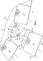
- Wear assembly 1 includes a wear member 3, a base 5, and a lock 7 to releasably secure the wear member ( Figs. 1 and 3 ).
- the wear assembly fits over and is secured to a lip 12 of a bucket or the like.
- Lip 12 includes an inside face 14, an outside face 16, and a front edge 17 ( Fig. 2 ).
- Scallops or recesses 18 are preferably formed along the front edge 17 to accommodate passage of lock 7.
- Scallops 18 are each preferably formed to have a uniform, continual, arcuate surface 19 with a curvature that extends no more than about 180 degrees about an axis extending generally perpendicular to the lip to be easily manufactured and provide a robust base to resist the applied loads.
- the scallops could be formed to have a non-uniform curvature, a discontinuous or angular shape, and/or be formed to have full or partial closure. In some circumstances, the scallops could be omitted with the boss extending farther forward from the lip.
- a base 5 is fixed to lip 12 over each scallop 18 ( Fig. 1 ). While bases 5 are preferably welded to the lip, they could be cast as an integral part of the lip or secured by mechanical means. In addition, the bases could each be formed as a multiple of parts, which are integral or spaced apart, although a one-piece member is preferred for simplicity and strength.
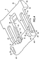
- Each base 5 has a pair of legs 21, 22 that straddle lip 12 ( Figs. 1 and 3-5 ).
- a first or inside leg 21 sets along inside surface 14 of lip 12 while a second or outside leg 22 sets along outside surface 16. Outside leg 22 is longer than inside leg 21 to interlock with base 5. However, the legs could be the same length or the inside leg longer.
- the base could have the opposite orientation with first leg 21 extending along outside face 16 and second leg 22 along inside face 14. Legs 21, 22 are interconnected by a front end 20.
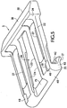
- the second leg 22 includes a central, axial groove 26 provided with a pair of inwardly projecting rails 24 along its opposite sides 23 ( Fig. 4 ). Rails 24 define holding surfaces 25 that are spaced from and facing outside face 16. Rails 24 cooperate with complementary rails 27 of wear member 3 to prevent the movement of leg 22 away from the lip. In some circumstances, for example, lower stress environments, the rails could be omitted entirely (not shown) so that the slot provides lateral support.
- a brace 30 is preferably provided at the rear end of second leg 22 ( Figs. 4 and 5 ), though it could be omitted. In this construction, groove 26 extends into brace 30 to define an opening 31, which is between brace 30 and outer wall 16 when the base is welded to lip 12.
- groove 26 could extend entirely through brace 30 to define an opening that is open on both ends.
- the opening could also be defined in leg 22 without the addition of the brace. In either case, opening 31 receives a support 33 of wear member 3 to strengthen and resist breakage of the wear member under heavy loading.
- Groove 26 also opens forwardly through the front end 20 of base 5 and is generally aligned with scallop 18.
- Brace 30 also preferably extends transversely beyond leg 22 to define a front wall 34 to abut the rear end 35 of shroud 3 and thereby reduce the rearward shifting of the shroud under load, which in turn, reduces the stress and wearing of wear member 3 on base 5.
- Brace 30 also preferably has an equal or greater depth than leg 22 to maximize the surface area in abutment with shroud 3, and to function as a deflector for earthen material when the movement of the bucket is reversed.
- a deflector face 36 inclined forward from outer face 16 is preferably formed along the rear side of brace 30 to direct the earthen material away from the assembled base and shroud.
- Leg 22 is preferably formed as an open framework with openings 37 to reduce the amount of needed steel and to facilitate welding of the base to the lip.
- the front end 20 of base 5 wraps around front edge 17 of lip 12 such that the interior surface 40 of the base (i.e., the surface that faces lip 12) is shaped to generally conform to the shape of the particular lip to which it is fixed ( Figs. 1 , 4 and 5 ), although derivations are possible.
- interior surface 40 includes an upright face 41 to set against front edge 17, an upper face 42 to set against ramp 43 of inside face 14, and a lower face 44 to set against outside surface 16. If the front of the lip had a curved or other shape, interior surface 40 would be changed to accommodate the shape of the lip.
- the front end 20 of base 5 preferably has a curved front bearing surface 48 to minimize stress concentrations and wearing between the wear member and the base. In a preferred construction, front surface 48 has a generally uniform curvature, though other configurations are possible.
- a recess 51 is formed in first leg 21 in vertical alignment with groove 26 for receiving lock 7.
- Stabilizing surfaces 49 are formed in front end 20 proximate both legs 21, 22 to engage complementary stabilizing surfaces 50 on wear member 3 ( figs 1 , 4 and 5 ). Stabilizing surfaces 49 are preferably limited in size so that front surface 48 is predominantly an uninterrupted generally uniform curved surface as it wraps around the front edge of the lip. The stabilizing surfaces are also preferably along the side 93 of base 5 for stability but could be provided at other locations. Also, the upper and lower stabilizing surfaces 49 are generally aligned vertically by each side 93 such that the upper and lower stabilizing surfaces 49 by the one side 93 are generally aligned with each other, and the upper and lower stabilizing 49 by the other side 93 are generally aligned - though other positions are possible. Stabilizing surfaces 49, 50 are preferably planar and horizontal, i.e., parallel to the central axial plane P of lip 12.
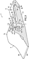
- Wear member 3 which is a shroud in the illustrated construction, has a front working portion 66 that tapers to a narrowed front edge 68, and a rear mounting portion 70 that is bifurcated to define a first or inside leg 72 and a second or outside leg 74 ( Figs. 1 , 3 and 6-8 ).
- the wear member is configured to set over base 5 with legs 72, 74 straddling lip 12.
- wear member 3 fits over lip 12 with first leg 72 overlying inside surface 14 and second leg 74 overlying outside surface 16. Nevertheless, the legs could be reversed so that first leg 72 is the outside leg and second leg 74 is the inside leg.
- Wear member 3 has an interior surface 80 that faces and overlies the lip.
- the interior surface 80 includes inner face 83 of outside leg 74, inner face 84 of inside leg 72, and the inner corner surface 86 at the intersection of legs 72, 74.
- Inner face 83 of leg 74 overlies leg 22 and outside face 16, and inside face 84 of leg 72 overlies leg 21 and inner face 14.
- Interior surface 80 along inner corner surface 86 has a central portion 88 and side portions 90.
- Central portion 88 generally matches front face 48 of base 5 and abuts against it during use.
- Central portion 88 is recessed relative to side portions 90 to form sidewalls 91 juxtaposed to sides 93 of base 5 for increased lateral support.
- interior surface 80 along central portion 88 defines a curved bearing surface 85 (preferably having a generally uniform curve) that opposes and abuts front bearing surface 48.
- curved bearing surface 85 preferably having a generally uniform curve
- the lack of edges on the front bearing surfaces of the wear member and the base reduces stress concentrations in the parts, i.e., the generally uniform matching curvature of the two surfaces at the front bearing surface reduces the concentration of stress that can occur in the corners of other parts as the wear part tends to shift on the base during use.
- a front end 89 of interior surface 80 forms the uniform curved surface 86 and a pair of stabilizing surfaces 50 ( Fig. 7 ) proximate each of the legs 72, 74 and central portion 88 to engage stabilizing surfaces 49 on base 5 ( Figs. 4 and 5 ).
- the stabilizing surfaces 49, 50 provide better resistance and greater stability to wear member 3 under vertical loading.
- the stabilizing surfaces 49, 50 are limited to discrete locations, preferably extending only a small portion across the front ends of the wear member 3 and base 5 (collectively no more than half), and are preferably located at the sides of bearing surfaces 48, 86 for increased stability. In this way, the benefit gained by the curved bearing surfaces is not lost by the use of the stabilizing surfaces 49, 50. Transition surfaces 81, 87 are provided to ease contact between stabilizing surfaces 49, 50 and to avoid sharp corners where stress may concentrate.
- Rib 82 is provided upstanding on the inner face 83 of leg 74 in an axial orientation for receipt within groove 26 ( Figs. 1 , 3 and 6-8 ).
- Rib 82 includes rails 27 that cooperate with rails 24; i.e., rails 27 are received between lip 12 and holding surfaces 25 of rails 24 to support wear member 3 under certain loads. While rib 82 with rails 84 preferably has a T-shaped configuration, other shapes, such as dovetail, could be used. Alternatively, there could be no rails in certain situations such as low load environments. Rib 82 preferably extends over at least half of leg 22, and most preferably over substantially the entire length of inner surface 83, for receipt within groove 26 to maximize the support available.
- the groove could be formed on wear member 3 and the rib on base 5.
- shroud 3 When shroud 3 is installed, it is slid over base 5 and lip 12 such that inside and outside legs 72, 74 straddle base 5 and lip 12.
- Rib 82 is slid into the open front end 75 of groove 26 in an easy to use manner so that rails 27 cooperate with rails 24 to hold leg 22 to lip 12.
- rib 82 extends beyond the rear end of leg 74 to define a support 33 that is received in opening 31 beneath brace 30, although other kinds of rearward supports could be used.
- support 33 could be forward of the rear end of leg 74 provided it included a holding surface 95 free of the leg and facing away from the lip to engage a complementary support surface (like 94) of leg 74.
- Support 33 is held between a support surface 94 and lip 12 for enhanced support of the wear member 3.
- the cooperation of support 33 and brace 30 supplements the resistance provided by rails 24, 27. By providing such a support at the rear end of leg 22, bending of the legs can be reduced, which in turn, lessens the risk of breaking the part.
- Wear member 3 is assembled over base 5 with a direct, continuous rearward sliding motion where rib 82 is slid through open end 75 and into groove 26. The rearward movement of wear member 3 over base 5 is continued until inside corner surface 86 abuts front face 48 of base 5 ( Figs. 3 and 11 ).
- rear wall 35 of outside leg 74 is preferably placed in close proximity to stop surface 34. With cast parts, it is not practical for inside corner surface 86 and rear wall 35 to simultaneously abut front face 48 and stop surface 34, respectively. However, by placing rear wall 35 in close proximity with stop surface 34, the two surfaces will typically abut under certain loads and after a period of time as wear develops in the parts. While it is not preferred, stop surface 34 could be the primary bearing surface that first abuts rear wall 35, with inside corner surface 86 abutting front face 48 second.
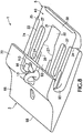
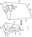
- Lock 7 includes a body 101 with a front face 103 and a rear face 105, and a movable latch 107 ( Figs. 9 and 10 ).
- lock 7 is inserted into hole 96 such that front face 103 opposes a rearwardly facing abutting wall 111 in recess 51, and rear face 105 opposes rear wall 113 in hole 96 and front wall 115 of rib 82 ( Figs. 1 and 3 ).
- this wall could be formed by another projection or by an opening in leg 22.
- Latch 107 includes a rigid part 121 preferably composed of steel provided with a locking projection 122, and a resilient part 123 preferably formed of foam, rubber or other elastomer.
- the bottom end of rigid part 121 defines a fulcrum 130 to fit within recess 132 to form a pivot axis about which latch 107 moves.
- the resilient part preferably includes detents 125 for receipt within matching grooves 127 in body 101 to retain the latch in cavity 129, but could be secured by other means.
- latch 107 is pressed rearward against the bias of resilient part 123 by its engagement against wear member 3.
- a curved slope 131 eases the latch rearward into cavity 129 during insertion.
- the resilient part 123 biases rigid part 121 outward such that projection 122 engages beneath stop 133 to retain lock 7 in wear assembly 10.
- a pry tool is inserted along the curved slope 131 to retract latch 107 into cavity 129 until stop 133 is released. The pry tool can, through engagement with ledge 137 of latch 107, pull lock 7 from passage 54.
- top face 139 of rigid part 121 abuts top wall 141 of cavity 129 to enable the lock to be pried out through engagement with the latch.
- Pry slot 126 is also preferably formed on rear face 105 to engage either a second pry tool or an alternative pry location to help remove lock 7 from passage 54.
- a hole 128 in the back of the lock allows rock fines to be pushed out of cavity 129.
- a notch 117 is formed on top wall 119 to accommodate the receipt of a pry tool during installation. Other means for inserting or removing the locks, or the use of other locks are possible.
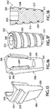
- lock 200 can be used to secure wear member 3 to lip 12 ( Figs. 12-18 ).
- lock 200 uses a threaded wedge 202 such as disclosed in U.S. Patent No. 7,171,771 instead of the elastomer as used in lock 7.
- Threaded wedge 202 has a rounded exterior 208 that tapers from the trailing end 210 to the leading end 212 ( Fig. 17 ).
- a helical groove 213 preferably extends the entire length of the wedge, though some portions of the wedge could remain unthreaded.
- a tool-engaging formation 214 for receiving a wrench or other tool is defined in trailing end 210 for turning of the wedge.
- Lock 200 also includes a body 204 and a latch 206 that are similar to the body and latch in lock 7 ( Figs. 12-16 ).
- Body 204 is formed with a channel 230 that receives latch 206 and threaded wedge 202 ( Fig. 14 ).
- a hole 232 is formed in top side 234 to define an inlet end for receiving threaded wedge 202 into channel 230.
- a trough 236 with threads 238 in the form of at least one helical ridge segment and preferably a plurality of helical ridge segments 238a is preferably provided along the rear wall 239 of channel 230 to engage the helical groove 213 on threaded wedge 202.
- a recess 218 is formed at the bottom of channel 208 to receive and form a pivot support for fulcrum 220 of latch 206.
- latch 206 has essentially the same construction and function as latch 107; i.e., latch 206 has a locking projection 218, a fulcrum 220, a ledge 222 and a top face 224 ( Figs. 12 , 15 and 16 ).
- rear side 216 includes a recess 226 adapted to receive a front portion of threaded wedge 202 ( Fig. 16 ).
- Retainers preferably in the form of elastomeric brakes 228 or the like, may be optionally provided to press against wedge 202 and resist its loosening during use.
- a resilient material 229 may optionally be provided within helical groove 213 of threaded wedge 202 to engage ridges 238 and thereby resist loosening of the wedge ( Fig. 18 ).
- the resilient material 229 is preferably a strip of rubber, foam, or other elastomer which is fixed within helical groove 213 by an adhesive.
- the resilient strip 229 preferably extends the entire length of groove 213, but could be formed only along part of the groove.
- the resilient strip 229 could be used alone or in combination with brakes 228.
- the threaded wedge 202 with resilient strip 229 can also be used in other wear assemblies such as disclosed in U.S. Patent Nos. 6,986,216 and 7,174,661 and U.S. Patent Application Serial No. 11/818,483, filed June 13, 2007 .
- lock 200 is inserted into assembly 1 like lock 7 ( Fig. 12 ).
- Lock 200 is preferably inserted into wear assembly 1 with threaded wedge 202 partially inserted into channel 230, but the wedge could be installed after body 204 is placed into the assembly. Threaded wedge 202 is then threaded farther into channel 230 to force latch 206 forward so that locking projection 218 engages stop 133 to retain lock 200 in the assembly during use.
- a tool-engaging formation 240 is preferably provided at trailing end 210 of wedge 202 to facilitate its turning.
Landscapes
- Engineering & Computer Science (AREA)
- Mining & Mineral Resources (AREA)
- Civil Engineering (AREA)
- General Engineering & Computer Science (AREA)
- Structural Engineering (AREA)
- Component Parts Of Construction Machinery (AREA)
Claims (7)
- Verrou (200) pour fixer un élément d'usure à un équipement d'excavation, comprenant un corps (204) incluant un passage avec une extrémité d'entrée ouverte (232), un loquet (206) pour le mouvement entre une position de retenue et une position de libération, et un coin (202) présentant une extrémité avant (212) et une extrémité arrière (210), le coin (202) s'effilant vers l'extrémité avant (212) et étant reçu de manière mobile dans le passage du corps (204) par l'extrémité d'entrée (232), le coin (202) engageant le loquet (206) pour déplacer le loquet (206) de la position de libération à la position de retenue lorsque l'extrémité avant (212) du coin (202) est déplacée plus loin dans le passage à l'écart de l'extrémité d'entrée (232),
caractérisé en ce que
le loquet (206) est attaché au corps (204), et le loquet (206) a une saillie de verrouillage (218) qui est adaptée pour s'engager sous une butée d'un dit élément d'usure lorsque le coin est déplacé plus loin dans le passage pour retenir le verrou (200) dans l'élément d'usure. - Verrou (200) selon la revendication 1, dans lequel le passage comprend une première formation filetée (238) et le coin (202) comporte une seconde formation filetée qui engage la première formation filetée (238) et dans lequel le coin (202) est tourné pour déplacer le coin (202) dans le passage.
- Verrou (200) selon la revendication 2, dans lequel la seconde formation filetée est formée par une rainure hélicoïdale (213) sur le coin (202).
- Verrou (200) selon la revendication 3, dans lequel un matériau élastique (229) est prévu dans la rainure hélicoïdale (213) pour engager la première formation filetée (238) et résister au relâchement du coin (202).
- Verrou (200) selon la revendication 1, dans lequel l'extrémité arrière (210) du coin (202) comporte une formation d'engagement d'outil (240) pour l'engagement d'un outil pour tourner le coin (202).
- Verrou (200) selon la revendication 1, dans lequel le loquet (206) est fixé de manière pivotante au corps (204).
- Verrou (200) selon la revendication 6, dans lequel le loquet (206) comporte un élément de retenue élastique qui engage le coin (202) pour résister au relâchement du coin (202).
Applications Claiming Priority (2)
| Application Number | Priority Date | Filing Date | Title |
|---|---|---|---|
| US85390806P | 2006-10-24 | 2006-10-24 | |
| PCT/US2007/082218 WO2008051966A2 (fr) | 2006-10-24 | 2007-10-23 | Ensemble d'usure pour godet d'excavation |
Publications (3)
| Publication Number | Publication Date |
|---|---|
| EP2076633A2 EP2076633A2 (fr) | 2009-07-08 |
| EP2076633A4 EP2076633A4 (fr) | 2014-05-07 |
| EP2076633B1 true EP2076633B1 (fr) | 2016-12-07 |
Family
ID=39325334
Family Applications (1)
| Application Number | Title | Priority Date | Filing Date |
|---|---|---|---|
| EP07854338.6A Active EP2076633B1 (fr) | 2006-10-24 | 2007-10-23 | Ensemble d'usure pour godet d'excavation |
Country Status (14)
| Country | Link |
|---|---|
| EP (1) | EP2076633B1 (fr) |
| CN (1) | CN101529023B (fr) |
| AU (1) | AU2007309015B2 (fr) |
| BR (1) | BRPI0717340B1 (fr) |
| CA (1) | CA2663881C (fr) |
| CL (1) | CL2007003063A1 (fr) |
| ES (1) | ES2611991T3 (fr) |
| HK (1) | HK1131647A1 (fr) |
| NZ (1) | NZ575959A (fr) |
| PE (1) | PE20081127A1 (fr) |
| PL (1) | PL2076633T3 (fr) |
| PT (1) | PT2076633T (fr) |
| WO (1) | WO2008051966A2 (fr) |
| ZA (1) | ZA200902334B (fr) |
Families Citing this family (14)
| Publication number | Priority date | Publication date | Assignee | Title |
|---|---|---|---|---|
| CN102686810B (zh) * | 2009-10-30 | 2015-07-08 | 爱斯科公司 | 用于挖掘设备的磨耗组件 |
| KR102134646B1 (ko) * | 2011-11-23 | 2020-07-16 | 에스코 그룹 엘엘씨 | 마모 조립체 |
| US8925220B2 (en) * | 2012-02-17 | 2015-01-06 | Esco Corporation | Wear assembly |
| US8819967B2 (en) * | 2012-03-21 | 2014-09-02 | Hensley Industries, Inc. | Adapter stabilization structure for bucket lip |
| USD769945S1 (en) | 2014-12-05 | 2016-10-25 | Caterpillar Inc. | Sidebar protector |
| US9903101B2 (en) * | 2014-12-05 | 2018-02-27 | Caterpillar Inc. | Replaceable shroud for work implement |
| US9493926B2 (en) * | 2015-02-02 | 2016-11-15 | Caterpillar Inc. | Pin assembly for work implement coupling assembly having float and lock positions |
| KR101945606B1 (ko) * | 2015-02-13 | 2019-02-07 | 블랙 캣 블레이즈 리미티드 | 굴착 장비를 위한 마모 부재 |
| USD788826S1 (en) | 2016-02-09 | 2017-06-06 | Caterpillar Inc. | Sidebar protector |
| EA201892623A1 (ru) * | 2016-05-05 | 2019-05-31 | ЭСКО ГРУП ЛЛСи | Изнашиваемая деталь для землеройного оборудования |
| US10480162B2 (en) * | 2016-12-15 | 2019-11-19 | Caterpillar Inc. | Implement ground engaging tip assembly having tip with tapered retention channel |
| CN107386348B (zh) * | 2017-08-22 | 2020-05-19 | 瑞安市佰德装饰工程有限公司 | 一种利用弧形轨驱动且能调节挖土方向的挖掘机铲斗 |
| USD882646S1 (en) | 2018-11-09 | 2020-04-28 | Caterpillar Inc. | Bucket shroud |
| CA3221630A1 (fr) * | 2021-06-09 | 2022-12-15 | Christopher David EDMONDS | Ensemble d'usure |
Family Cites Families (12)
| Publication number | Priority date | Publication date | Assignee | Title |
|---|---|---|---|---|
| US2395288A (en) | 1943-06-30 | 1946-02-19 | Frank W Thomas | Inserted blade cutter |
| US2435287A (en) * | 1944-05-12 | 1948-02-03 | Robert W Thomas | Cutting tool |
| US4570365A (en) | 1983-11-23 | 1986-02-18 | Bierwith Robert S | Digging tooth and bucket lip construction |
| US5088214A (en) | 1991-01-17 | 1992-02-18 | Esco Corporation | Excavator wear edge |
| US5311681A (en) * | 1992-04-08 | 1994-05-17 | Gh Hensley Industries, Inc. | Retaining mechanism |
| CN2286204Y (zh) * | 1997-01-21 | 1998-07-15 | 湘潭电气设备制造有限责任公司 | 挖掘机回转机构的保护装置 |
| AUPO657997A0 (en) * | 1997-05-02 | 1997-05-29 | Hedweld Engineering Pty. Ltd. | A tooth wedge assembly |
| AUPO842697A0 (en) * | 1997-08-06 | 1997-08-28 | Cutting Edges Replacement Parts Pty Ltd | Connection pin assembly |
| US6108950A (en) * | 1999-03-08 | 2000-08-29 | Gh Hensley Industries, Inc. | Self-adjusting tooth/adapter connection system for material displacement apparatus |
| US6729052B2 (en) * | 2001-11-09 | 2004-05-04 | Esco Corporation | Assembly for securing an excavating tooth |
| US7171771B2 (en) | 2003-04-30 | 2007-02-06 | Esco Corporation | Releasable coupling assembly |
| US7080470B2 (en) | 2003-04-30 | 2006-07-25 | Esco Corporation | Wear assembly for excavator digging edge |
-
2007
- 2007-10-23 BR BRPI0717340-7A patent/BRPI0717340B1/pt not_active IP Right Cessation
- 2007-10-23 AU AU2007309015A patent/AU2007309015B2/en not_active Ceased
- 2007-10-23 CA CA2663881A patent/CA2663881C/fr not_active Expired - Fee Related
- 2007-10-23 PE PE2007001434A patent/PE20081127A1/es active IP Right Grant
- 2007-10-23 PL PL07854338T patent/PL2076633T3/pl unknown
- 2007-10-23 EP EP07854338.6A patent/EP2076633B1/fr active Active
- 2007-10-23 PT PT78543386T patent/PT2076633T/pt unknown
- 2007-10-23 NZ NZ575959A patent/NZ575959A/en not_active IP Right Cessation
- 2007-10-23 ES ES07854338.6T patent/ES2611991T3/es active Active
- 2007-10-23 CN CN200780039098XA patent/CN101529023B/zh not_active Expired - Fee Related
- 2007-10-23 WO PCT/US2007/082218 patent/WO2008051966A2/fr active Application Filing
- 2007-10-24 CL CL200703063A patent/CL2007003063A1/es unknown
-
2009
- 2009-04-03 ZA ZA200902334A patent/ZA200902334B/xx unknown
- 2009-11-30 HK HK09111191.5A patent/HK1131647A1/xx not_active IP Right Cessation
Also Published As
| Publication number | Publication date |
|---|---|
| PE20081127A1 (es) | 2008-08-15 |
| CA2663881A1 (fr) | 2008-05-02 |
| EP2076633A2 (fr) | 2009-07-08 |
| PT2076633T (pt) | 2017-01-31 |
| WO2008051966A3 (fr) | 2008-11-06 |
| CN101529023A (zh) | 2009-09-09 |
| EP2076633A4 (fr) | 2014-05-07 |
| BRPI0717340A2 (pt) | 2013-12-10 |
| CA2663881C (fr) | 2012-08-07 |
| NZ575959A (en) | 2011-06-30 |
| ZA200902334B (en) | 2010-04-28 |
| WO2008051966A2 (fr) | 2008-05-02 |
| PL2076633T3 (pl) | 2017-06-30 |
| BRPI0717340B1 (pt) | 2017-12-19 |
| HK1131647A1 (en) | 2010-01-29 |
| ES2611991T3 (es) | 2017-05-11 |
| AU2007309015B2 (en) | 2010-12-16 |
| AU2007309015A1 (en) | 2008-05-02 |
| CN101529023B (zh) | 2012-03-07 |
| CL2007003063A1 (es) | 2008-05-16 |
Similar Documents
| Publication | Publication Date | Title |
|---|---|---|
| US7526886B2 (en) | Wear assembly for an excavating bucket | |
| EP2076633B1 (fr) | Ensemble d'usure pour godet d'excavation | |
| US20080092412A1 (en) | Wear Assembly For An Excavating Bucket | |
| JP5005341B2 (ja) | 掘削機の掘削縁部用の磨耗アッセンブリ | |
| AU2007261586B2 (en) | Lock for securing wear parts to earth-working equipment | |
| CA2451309C (fr) | Ensemble d'usure | |
| EP1984575B1 (fr) | Ensemble d'usure | |
| AU2005230932B2 (en) | Wear edge assembly | |
| US7874086B2 (en) | Lock assembly for securing a wear member to earth-working equipment | |
| ES2889931T3 (es) | Conjuntos de acoplamiento con tracción mejorada para equipos de excavación | |
| US20030007831A1 (en) | Lock with internal retainer | |
| EP2016230A2 (fr) | Ensemble anti-usure | |
| AU2013202717B2 (en) | Lock for securing wear parts to earth-working equipment | |
| WO2008130360A1 (fr) | Ensemble de verrouillage pour fixer un élément d'usure à un équipement de terrassement | |
| AU2013205257A1 (en) | Wear assembly |
Legal Events
| Date | Code | Title | Description |
|---|---|---|---|
| PUAI | Public reference made under article 153(3) epc to a published international application that has entered the european phase |
Free format text: ORIGINAL CODE: 0009012 |
|
| 17P | Request for examination filed |
Effective date: 20090325 |
|
| AK | Designated contracting states |
Kind code of ref document: A2 Designated state(s): AT BE BG CH CY CZ DE DK EE ES FI FR GB GR HU IE IS IT LI LT LU LV MC MT NL PL PT RO SE SI SK TR |
|
| DAX | Request for extension of the european patent (deleted) | ||
| A4 | Supplementary search report drawn up and despatched |
Effective date: 20140408 |
|
| RIC1 | Information provided on ipc code assigned before grant |
Ipc: E02F 9/28 20060101AFI20140402BHEP |
|
| GRAP | Despatch of communication of intention to grant a patent |
Free format text: ORIGINAL CODE: EPIDOSNIGR1 |
|
| INTG | Intention to grant announced |
Effective date: 20160525 |
|
| GRAS | Grant fee paid |
Free format text: ORIGINAL CODE: EPIDOSNIGR3 |
|
| GRAA | (expected) grant |
Free format text: ORIGINAL CODE: 0009210 |
|
| STAA | Information on the status of an ep patent application or granted ep patent |
Free format text: STATUS: THE PATENT HAS BEEN GRANTED |
|
| AK | Designated contracting states |
Kind code of ref document: B1 Designated state(s): AT BE BG CH CY CZ DE DK EE ES FI FR GB GR HU IE IS IT LI LT LU LV MC MT NL PL PT RO SE SI SK TR |
|
| REG | Reference to a national code |
Ref country code: GB Ref legal event code: FG4D |
|
| REG | Reference to a national code |
Ref country code: CH Ref legal event code: EP Ref country code: AT Ref legal event code: REF Ref document number: 851846 Country of ref document: AT Kind code of ref document: T Effective date: 20161215 |
|
| REG | Reference to a national code |
Ref country code: IE Ref legal event code: FG4D |
|
| REG | Reference to a national code |
Ref country code: DE Ref legal event code: R096 Ref document number: 602007049083 Country of ref document: DE |
|
| REG | Reference to a national code |
Ref country code: PT Ref legal event code: SC4A Ref document number: 2076633 Country of ref document: PT Date of ref document: 20170131 Kind code of ref document: T Free format text: AVAILABILITY OF NATIONAL TRANSLATION Effective date: 20170119 |
|
| REG | Reference to a national code |
Ref country code: SE Ref legal event code: TRGR |
|
| PG25 | Lapsed in a contracting state [announced via postgrant information from national office to epo] |
Ref country code: LV Free format text: LAPSE BECAUSE OF FAILURE TO SUBMIT A TRANSLATION OF THE DESCRIPTION OR TO PAY THE FEE WITHIN THE PRESCRIBED TIME-LIMIT Effective date: 20161207 |
|
| REG | Reference to a national code |
Ref country code: LT Ref legal event code: MG4D |
|
| REG | Reference to a national code |
Ref country code: NL Ref legal event code: MP Effective date: 20161207 |
|
| PG25 | Lapsed in a contracting state [announced via postgrant information from national office to epo] |
Ref country code: GR Free format text: LAPSE BECAUSE OF FAILURE TO SUBMIT A TRANSLATION OF THE DESCRIPTION OR TO PAY THE FEE WITHIN THE PRESCRIBED TIME-LIMIT Effective date: 20170308 Ref country code: LT Free format text: LAPSE BECAUSE OF FAILURE TO SUBMIT A TRANSLATION OF THE DESCRIPTION OR TO PAY THE FEE WITHIN THE PRESCRIBED TIME-LIMIT Effective date: 20161207 |
|
| REG | Reference to a national code |
Ref country code: ES Ref legal event code: FG2A Ref document number: 2611991 Country of ref document: ES Kind code of ref document: T3 Effective date: 20170511 |
|
| REG | Reference to a national code |
Ref country code: AT Ref legal event code: MK05 Ref document number: 851846 Country of ref document: AT Kind code of ref document: T Effective date: 20161207 |
|
| PG25 | Lapsed in a contracting state [announced via postgrant information from national office to epo] |
Ref country code: NL Free format text: LAPSE BECAUSE OF FAILURE TO SUBMIT A TRANSLATION OF THE DESCRIPTION OR TO PAY THE FEE WITHIN THE PRESCRIBED TIME-LIMIT Effective date: 20161207 |
|
| PG25 | Lapsed in a contracting state [announced via postgrant information from national office to epo] |
Ref country code: EE Free format text: LAPSE BECAUSE OF FAILURE TO SUBMIT A TRANSLATION OF THE DESCRIPTION OR TO PAY THE FEE WITHIN THE PRESCRIBED TIME-LIMIT Effective date: 20161207 Ref country code: SK Free format text: LAPSE BECAUSE OF FAILURE TO SUBMIT A TRANSLATION OF THE DESCRIPTION OR TO PAY THE FEE WITHIN THE PRESCRIBED TIME-LIMIT Effective date: 20161207 Ref country code: CZ Free format text: LAPSE BECAUSE OF FAILURE TO SUBMIT A TRANSLATION OF THE DESCRIPTION OR TO PAY THE FEE WITHIN THE PRESCRIBED TIME-LIMIT Effective date: 20161207 Ref country code: RO Free format text: LAPSE BECAUSE OF FAILURE TO SUBMIT A TRANSLATION OF THE DESCRIPTION OR TO PAY THE FEE WITHIN THE PRESCRIBED TIME-LIMIT Effective date: 20161207 Ref country code: IS Free format text: LAPSE BECAUSE OF FAILURE TO SUBMIT A TRANSLATION OF THE DESCRIPTION OR TO PAY THE FEE WITHIN THE PRESCRIBED TIME-LIMIT Effective date: 20170407 |
|
| PG25 | Lapsed in a contracting state [announced via postgrant information from national office to epo] |
Ref country code: IT Free format text: LAPSE BECAUSE OF FAILURE TO SUBMIT A TRANSLATION OF THE DESCRIPTION OR TO PAY THE FEE WITHIN THE PRESCRIBED TIME-LIMIT Effective date: 20161207 Ref country code: BE Free format text: LAPSE BECAUSE OF FAILURE TO SUBMIT A TRANSLATION OF THE DESCRIPTION OR TO PAY THE FEE WITHIN THE PRESCRIBED TIME-LIMIT Effective date: 20161207 Ref country code: AT Free format text: LAPSE BECAUSE OF FAILURE TO SUBMIT A TRANSLATION OF THE DESCRIPTION OR TO PAY THE FEE WITHIN THE PRESCRIBED TIME-LIMIT Effective date: 20161207 |
|
| REG | Reference to a national code |
Ref country code: DE Ref legal event code: R097 Ref document number: 602007049083 Country of ref document: DE |
|
| PLBE | No opposition filed within time limit |
Free format text: ORIGINAL CODE: 0009261 |
|
| STAA | Information on the status of an ep patent application or granted ep patent |
Free format text: STATUS: NO OPPOSITION FILED WITHIN TIME LIMIT |
|
| 26N | No opposition filed |
Effective date: 20170908 |
|
| PG25 | Lapsed in a contracting state [announced via postgrant information from national office to epo] |
Ref country code: DK Free format text: LAPSE BECAUSE OF FAILURE TO SUBMIT A TRANSLATION OF THE DESCRIPTION OR TO PAY THE FEE WITHIN THE PRESCRIBED TIME-LIMIT Effective date: 20161207 Ref country code: SI Free format text: LAPSE BECAUSE OF FAILURE TO SUBMIT A TRANSLATION OF THE DESCRIPTION OR TO PAY THE FEE WITHIN THE PRESCRIBED TIME-LIMIT Effective date: 20161207 |
|
| PG25 | Lapsed in a contracting state [announced via postgrant information from national office to epo] |
Ref country code: MC Free format text: LAPSE BECAUSE OF FAILURE TO SUBMIT A TRANSLATION OF THE DESCRIPTION OR TO PAY THE FEE WITHIN THE PRESCRIBED TIME-LIMIT Effective date: 20161207 |
|
| REG | Reference to a national code |
Ref country code: CH Ref legal event code: PL |
|
| GBPC | Gb: european patent ceased through non-payment of renewal fee |
Effective date: 20171023 |
|
| REG | Reference to a national code |
Ref country code: IE Ref legal event code: MM4A |
|
| REG | Reference to a national code |
Ref country code: FR Ref legal event code: ST Effective date: 20180629 |
|
| PG25 | Lapsed in a contracting state [announced via postgrant information from national office to epo] |
Ref country code: LI Free format text: LAPSE BECAUSE OF NON-PAYMENT OF DUE FEES Effective date: 20171031 Ref country code: CH Free format text: LAPSE BECAUSE OF NON-PAYMENT OF DUE FEES Effective date: 20171031 Ref country code: LU Free format text: LAPSE BECAUSE OF NON-PAYMENT OF DUE FEES Effective date: 20171023 Ref country code: GB Free format text: LAPSE BECAUSE OF NON-PAYMENT OF DUE FEES Effective date: 20171023 |
|
| PG25 | Lapsed in a contracting state [announced via postgrant information from national office to epo] |
Ref country code: FR Free format text: LAPSE BECAUSE OF NON-PAYMENT OF DUE FEES Effective date: 20171031 |
|
| PG25 | Lapsed in a contracting state [announced via postgrant information from national office to epo] |
Ref country code: MT Free format text: LAPSE BECAUSE OF NON-PAYMENT OF DUE FEES Effective date: 20171023 |
|
| PG25 | Lapsed in a contracting state [announced via postgrant information from national office to epo] |
Ref country code: IE Free format text: LAPSE BECAUSE OF NON-PAYMENT OF DUE FEES Effective date: 20171023 |
|
| PGFP | Annual fee paid to national office [announced via postgrant information from national office to epo] |
Ref country code: LU Payment date: 20181219 Year of fee payment: 12 Ref country code: DE Payment date: 20181029 Year of fee payment: 12 Ref country code: PT Payment date: 20181008 Year of fee payment: 12 |
|
| PG25 | Lapsed in a contracting state [announced via postgrant information from national office to epo] |
Ref country code: HU Free format text: LAPSE BECAUSE OF FAILURE TO SUBMIT A TRANSLATION OF THE DESCRIPTION OR TO PAY THE FEE WITHIN THE PRESCRIBED TIME-LIMIT; INVALID AB INITIO Effective date: 20071023 |
|
| PG25 | Lapsed in a contracting state [announced via postgrant information from national office to epo] |
Ref country code: CY Free format text: LAPSE BECAUSE OF NON-PAYMENT OF DUE FEES Effective date: 20161207 |
|
| REG | Reference to a national code |
Ref country code: DE Ref legal event code: R119 Ref document number: 602007049083 Country of ref document: DE |
|
| REG | Reference to a national code |
Ref country code: FI Ref legal event code: MAE |
|
| PG25 | Lapsed in a contracting state [announced via postgrant information from national office to epo] |
Ref country code: FI Free format text: LAPSE BECAUSE OF NON-PAYMENT OF DUE FEES Effective date: 20191023 Ref country code: PT Free format text: LAPSE BECAUSE OF NON-PAYMENT OF DUE FEES Effective date: 20200527 Ref country code: DE Free format text: LAPSE BECAUSE OF NON-PAYMENT OF DUE FEES Effective date: 20200501 |
|
| PGFP | Annual fee paid to national office [announced via postgrant information from national office to epo] |
Ref country code: TR Payment date: 20201013 Year of fee payment: 14 |
|
| PGFP | Annual fee paid to national office [announced via postgrant information from national office to epo] |
Ref country code: SE Payment date: 20201028 Year of fee payment: 14 |
|
| PGFP | Annual fee paid to national office [announced via postgrant information from national office to epo] |
Ref country code: PL Payment date: 20210129 Year of fee payment: 14 |
|
| PG25 | Lapsed in a contracting state [announced via postgrant information from national office to epo] |
Ref country code: ES Free format text: LAPSE BECAUSE OF NON-PAYMENT OF DUE FEES Effective date: 20191024 |
|
| REG | Reference to a national code |
Ref country code: SE Ref legal event code: EUG |
|
| PG25 | Lapsed in a contracting state [announced via postgrant information from national office to epo] |
Ref country code: SE Free format text: LAPSE BECAUSE OF NON-PAYMENT OF DUE FEES Effective date: 20211024 |
|
| PG25 | Lapsed in a contracting state [announced via postgrant information from national office to epo] |
Ref country code: BG Free format text: LAPSE BECAUSE OF FAILURE TO SUBMIT A TRANSLATION OF THE DESCRIPTION OR TO PAY THE FEE WITHIN THE PRESCRIBED TIME-LIMIT Effective date: 20161207 |
|
| PG25 | Lapsed in a contracting state [announced via postgrant information from national office to epo] |
Ref country code: PL Free format text: LAPSE BECAUSE OF NON-PAYMENT OF DUE FEES Effective date: 20211023 |